EP3476642A1 - Fuel tank - Google Patents
Fuel tank Download PDFInfo
- Publication number
- EP3476642A1 EP3476642A1 EP18202220.2A EP18202220A EP3476642A1 EP 3476642 A1 EP3476642 A1 EP 3476642A1 EP 18202220 A EP18202220 A EP 18202220A EP 3476642 A1 EP3476642 A1 EP 3476642A1
- Authority
- EP
- European Patent Office
- Prior art keywords
- plate portion
- strut
- fuel tank
- fuel
- penetrating hole
- Prior art date
- Legal status (The legal status is an assumption and is not a legal conclusion. Google has not performed a legal analysis and makes no representation as to the accuracy of the status listed.)
- Granted
Links
- 239000002828 fuel tank Substances 0.000 title claims abstract description 110
- 230000000149 penetrating effect Effects 0.000 claims abstract description 161
- 239000012530 fluid Substances 0.000 claims abstract description 20
- 239000000446 fuel Substances 0.000 claims description 112
- 238000005452 bending Methods 0.000 claims description 18
- 230000003014 reinforcing effect Effects 0.000 claims description 11
- 238000004891 communication Methods 0.000 claims description 4
- 230000007423 decrease Effects 0.000 claims description 4
- 238000004519 manufacturing process Methods 0.000 description 25
- 230000003116 impacting effect Effects 0.000 description 10
- 239000011435 rock Substances 0.000 description 9
- 230000000694 effects Effects 0.000 description 6
- 238000010586 diagram Methods 0.000 description 5
- 239000011347 resin Substances 0.000 description 3
- 229920005989 resin Polymers 0.000 description 3
- 230000003247 decreasing effect Effects 0.000 description 2
- 239000002184 metal Substances 0.000 description 2
- 230000001629 suppression Effects 0.000 description 2
- 230000001133 acceleration Effects 0.000 description 1
- 238000005516 engineering process Methods 0.000 description 1
- 238000003780 insertion Methods 0.000 description 1
- 230000037431 insertion Effects 0.000 description 1
- 239000000126 substance Substances 0.000 description 1
Images







Classifications
-
- B—PERFORMING OPERATIONS; TRANSPORTING
- B60—VEHICLES IN GENERAL
- B60K—ARRANGEMENT OR MOUNTING OF PROPULSION UNITS OR OF TRANSMISSIONS IN VEHICLES; ARRANGEMENT OR MOUNTING OF PLURAL DIVERSE PRIME-MOVERS IN VEHICLES; AUXILIARY DRIVES FOR VEHICLES; INSTRUMENTATION OR DASHBOARDS FOR VEHICLES; ARRANGEMENTS IN CONNECTION WITH COOLING, AIR INTAKE, GAS EXHAUST OR FUEL SUPPLY OF PROPULSION UNITS IN VEHICLES
- B60K15/00—Arrangement in connection with fuel supply of combustion engines or other fuel consuming energy converters, e.g. fuel cells; Mounting or construction of fuel tanks
- B60K15/03—Fuel tanks
- B60K15/077—Fuel tanks with means modifying or controlling distribution or motion of fuel, e.g. to prevent noise, surge, splash or fuel starvation
-
- B—PERFORMING OPERATIONS; TRANSPORTING
- B60—VEHICLES IN GENERAL
- B60K—ARRANGEMENT OR MOUNTING OF PROPULSION UNITS OR OF TRANSMISSIONS IN VEHICLES; ARRANGEMENT OR MOUNTING OF PLURAL DIVERSE PRIME-MOVERS IN VEHICLES; AUXILIARY DRIVES FOR VEHICLES; INSTRUMENTATION OR DASHBOARDS FOR VEHICLES; ARRANGEMENTS IN CONNECTION WITH COOLING, AIR INTAKE, GAS EXHAUST OR FUEL SUPPLY OF PROPULSION UNITS IN VEHICLES
- B60K15/00—Arrangement in connection with fuel supply of combustion engines or other fuel consuming energy converters, e.g. fuel cells; Mounting or construction of fuel tanks
- B60K15/03—Fuel tanks
- B60K15/03177—Fuel tanks made of non-metallic material, e.g. plastics, or of a combination of non-metallic and metallic material
-
- B—PERFORMING OPERATIONS; TRANSPORTING
- B60—VEHICLES IN GENERAL
- B60K—ARRANGEMENT OR MOUNTING OF PROPULSION UNITS OR OF TRANSMISSIONS IN VEHICLES; ARRANGEMENT OR MOUNTING OF PLURAL DIVERSE PRIME-MOVERS IN VEHICLES; AUXILIARY DRIVES FOR VEHICLES; INSTRUMENTATION OR DASHBOARDS FOR VEHICLES; ARRANGEMENTS IN CONNECTION WITH COOLING, AIR INTAKE, GAS EXHAUST OR FUEL SUPPLY OF PROPULSION UNITS IN VEHICLES
- B60K15/00—Arrangement in connection with fuel supply of combustion engines or other fuel consuming energy converters, e.g. fuel cells; Mounting or construction of fuel tanks
- B60K15/03—Fuel tanks
- B60K2015/03328—Arrangements or special measures related to fuel tanks or fuel handling
- B60K2015/0344—Arrangements or special measures related to fuel tanks or fuel handling comprising baffles
-
- B—PERFORMING OPERATIONS; TRANSPORTING
- B60—VEHICLES IN GENERAL
- B60K—ARRANGEMENT OR MOUNTING OF PROPULSION UNITS OR OF TRANSMISSIONS IN VEHICLES; ARRANGEMENT OR MOUNTING OF PLURAL DIVERSE PRIME-MOVERS IN VEHICLES; AUXILIARY DRIVES FOR VEHICLES; INSTRUMENTATION OR DASHBOARDS FOR VEHICLES; ARRANGEMENTS IN CONNECTION WITH COOLING, AIR INTAKE, GAS EXHAUST OR FUEL SUPPLY OF PROPULSION UNITS IN VEHICLES
- B60K15/00—Arrangement in connection with fuel supply of combustion engines or other fuel consuming energy converters, e.g. fuel cells; Mounting or construction of fuel tanks
- B60K15/03—Fuel tanks
- B60K2015/03328—Arrangements or special measures related to fuel tanks or fuel handling
- B60K2015/03453—Arrangements or special measures related to fuel tanks or fuel handling for fixing or mounting parts of the fuel tank together
-
- B—PERFORMING OPERATIONS; TRANSPORTING
- B60—VEHICLES IN GENERAL
- B60K—ARRANGEMENT OR MOUNTING OF PROPULSION UNITS OR OF TRANSMISSIONS IN VEHICLES; ARRANGEMENT OR MOUNTING OF PLURAL DIVERSE PRIME-MOVERS IN VEHICLES; AUXILIARY DRIVES FOR VEHICLES; INSTRUMENTATION OR DASHBOARDS FOR VEHICLES; ARRANGEMENTS IN CONNECTION WITH COOLING, AIR INTAKE, GAS EXHAUST OR FUEL SUPPLY OF PROPULSION UNITS IN VEHICLES
- B60K15/00—Arrangement in connection with fuel supply of combustion engines or other fuel consuming energy converters, e.g. fuel cells; Mounting or construction of fuel tanks
- B60K15/03—Fuel tanks
- B60K15/063—Arrangement of tanks
- B60K2015/0634—Arrangement of tanks the fuel tank is arranged below the vehicle floor
-
- B—PERFORMING OPERATIONS; TRANSPORTING
- B60—VEHICLES IN GENERAL
- B60K—ARRANGEMENT OR MOUNTING OF PROPULSION UNITS OR OF TRANSMISSIONS IN VEHICLES; ARRANGEMENT OR MOUNTING OF PLURAL DIVERSE PRIME-MOVERS IN VEHICLES; AUXILIARY DRIVES FOR VEHICLES; INSTRUMENTATION OR DASHBOARDS FOR VEHICLES; ARRANGEMENTS IN CONNECTION WITH COOLING, AIR INTAKE, GAS EXHAUST OR FUEL SUPPLY OF PROPULSION UNITS IN VEHICLES
- B60K15/00—Arrangement in connection with fuel supply of combustion engines or other fuel consuming energy converters, e.g. fuel cells; Mounting or construction of fuel tanks
- B60K15/03—Fuel tanks
- B60K15/077—Fuel tanks with means modifying or controlling distribution or motion of fuel, e.g. to prevent noise, surge, splash or fuel starvation
- B60K2015/0775—Fuel tanks with means modifying or controlling distribution or motion of fuel, e.g. to prevent noise, surge, splash or fuel starvation for reducing movement or slash noise of fuel
-
- B—PERFORMING OPERATIONS; TRANSPORTING
- B60—VEHICLES IN GENERAL
- B60K—ARRANGEMENT OR MOUNTING OF PROPULSION UNITS OR OF TRANSMISSIONS IN VEHICLES; ARRANGEMENT OR MOUNTING OF PLURAL DIVERSE PRIME-MOVERS IN VEHICLES; AUXILIARY DRIVES FOR VEHICLES; INSTRUMENTATION OR DASHBOARDS FOR VEHICLES; ARRANGEMENTS IN CONNECTION WITH COOLING, AIR INTAKE, GAS EXHAUST OR FUEL SUPPLY OF PROPULSION UNITS IN VEHICLES
- B60K15/00—Arrangement in connection with fuel supply of combustion engines or other fuel consuming energy converters, e.g. fuel cells; Mounting or construction of fuel tanks
- B60K15/03—Fuel tanks
- B60K15/077—Fuel tanks with means modifying or controlling distribution or motion of fuel, e.g. to prevent noise, surge, splash or fuel starvation
- B60K2015/0777—Fuel tanks with means modifying or controlling distribution or motion of fuel, e.g. to prevent noise, surge, splash or fuel starvation in-tank reservoirs or baffles integrally manufactured with the fuel Tank
Definitions
- the present disclosure relates to a fuel tank.
- Fuel tanks have a problem of fuel rocking within a fuel tank during acceleration or the like and noise being produced by the fuel impacting against wall faces of the tank.
- a structure has been proposed (see Japanese Patent Application Laid-Open ( JP-A) No. 2015-160500 ) in which a separator is attached to an outer wall of a fuel tank by a portion of a separator main body portion being inserted into an outer wall separator insertion hole formed in the tank outer wall and a separator attachment portion being welded to an outer face of the tank outer wall.
- the present disclosure provides a fuel tank that may further suppress the production of noise in the fuel tank.
- a fuel tank includes: a fuel tank main body that is enclosed by a floor wall, side walls and an upper wall, and inside which fuel is stored; and a separator including a strut provided at at least one of the floor wall or the upper wall, a first plate portion in which a first penetrating hole that penetrates in a plate thickness direction is formed, the first plate portion extending in a diametric direction from the strut, and a second plate portion in which a second penetrating hole that penetrates in a plate thickness direction is formed, the second plate portion sandwiching the strut with the first plate portion and extending in a diametric direction at an opposite side of the strut from a side thereof at which the first plate portion is disposed, wherein at least one of shapes, sizes or numbers of the first penetrating hole and the second penetrating hole is set to be different such that fluid resistances at the first plate portion and the second plate portion are different.
- This fuel tank is equipped with the separator that includes the first plate portion and the second plate portion that are provided to sandwich the strut from opposite sides of the strut. Consequently, rocking of the fuel is suppressed by the first plate portion and the second plate portion, and the production of noise in the fuel tank is suppressed.
- At least one of numbers, sizes and shapes of the first penetrating holes formed in the first plate portion and the second penetrating holes formed in the second plate portion is set to be different such that fluid resistances of the first plate portion and the second plate portion are different.
- first penetrating holes and second penetrating holes are formed such that the fluid resistance of the second plate portion is greater than the fluid resistance of the first plate portion
- a flow amount of fuel flowing through the first penetrating holes in the first plate portion with the smaller fluid resistance to the opposite side of the first plate portion in plan view is greater than a flow amount of fuel flowing through the second penetrating holes in the second plate portion with the larger fluid resistance to the opposite side of the second plate portion.
- the first penetrating holes or the second penetrating holes are formed in only one of the first plate portion and the second plate portion.
- the fluid resistance of the first plate portion in which the first penetrating holes are formed is lower than the fluid resistance of the second plate portion in which no second penetrating holes are formed.
- the first penetrating hole and the second penetrating hole are circular holes, and the first penetrating hole and the second penetrating hole differ in hole diameter.
- the hole diameters of the circular holes differ between the first penetrating holes and the second penetrating holes. For example, if the hole diameters of the first penetrating holes are greater than the hole diameters of the second penetrating holes, the fluid resistance of the first plate portion is smaller than the fluid resistance of the second plate portion. Thus, when the fuel rocks, a fuel flow amount passing through the first penetrating holes in the first plate portion is greater than a fuel flow amount passing through the second penetrating holes in the second plate portion.
- the first penetrating hole decreases in diameter from a face at one side of the first plate portion toward a face at another side thereof, and the second penetrating hole increases in diameter from a face at the one side of the second plate portion toward a face at the other side thereof.
- the first penetrating holes are formed with decreasing diameters from the face at the one side of the first plate portion toward the face at the other side
- the second penetrating holes are formed with increasing diameters from the face at the one side of the second plate portion toward the face at the other side.
- directions of taper (directions of increasing diameter) of the first penetrating holes and the second penetrating holes are opposite directions.
- a direction of rocking fuel is the direction of decreasing diameter of the first penetrating holes (the direction of increasing diameter of the second penetrating holes)
- an inflow amount of fuel passing through the first penetrating holes in the first plate portion is larger (a flow speed thereof is higher) and a flow amount of fuel passing through the second penetrating holes is smaller (a flow speed thereof is lower).
- a rotary flow of the fuel from the first plate portion toward the second plate portion around the strut in plan view occurs and amounts of rocking fuel approaching the side walls of the fuel tank main body via the first penetrating holes and second penetrating holes may be suppressed.
- the production of noise in the fuel tank main body may be further suppressed.
- a strut penetrating hole is formed, the strut penetrating hole penetrating through the strut in a same direction as a direction of extension of the first penetrating hole and the second penetrating hole.
- strut penetrating holes are formed penetrating through the strut in the same direction as the direction of extension of the first penetrating holes in the first plate portion and the second penetrating holes in the second plate portion, a flow of fuel passing through the separator is fragmented by passing through the first penetrating holes in the first plate portion and the second penetrating holes in the second plate portion and also passing through the strut penetrating holes.
- a flow speed (fluid energy) of the fuel that passes through is lowered further.
- the production of noise by rocking fuel impacting against the side walls of the fuel tank main body is even further suppressed.
- a fuel tank includes: a fuel tank main body that is enclosed by a floor wall, side walls and an upper wall, and inside which fuel is stored; and a separator including a strut provided at at least one of the floor wall and the upper wall, a first plate portion that extends in a diametric direction from the strut, or a second plate portion that sandwiches the strut with the first plate portion and extends in a diametric direction at an opposite side of the strut from a side thereof at which the first plate portion is disposed, wherein a bending stiffness of the first plate portion is different from a bending stiffness of the second plate portion.
- This fuel tank includes the separator that includes the first plate portion and the second plate portion that are provided to sandwich the strut from opposite sides of the strut. Because the first plate portion and the second plate portion have different bending stiffnesses, when fuel is rocking in the fuel tank main body, bending deformation amounts of the first plate portion and the second plate portion are different.
- the bending stiffness of the second plate portion is higher than the bending stiffness of the first plate portion, then when the fuel rocks, a flow amount of fuel passing through the vicinity of the first plate portion whose bending deformation amount is relatively large is greater than a flow amount of fuel passing through the vicinity of the second plate portion.
- a flow of fuel from the first plate portion toward the second plate portion around the strut in plan view is produced. Consequently, a flow amount of rocking fuel toward the side walls of the fuel tank main body is suppressed.
- the production of noise by rocking fuel impacting against the side walls of the fuel tank main body is suppressed.
- a reinforcing rib is formed at at least one of the first plate portion or the second plate portion.
- the reinforcing rib is provided at the at least one of the first plate portion and the second plate portion, the bending stiffness of the one plate portion is set to be higher than the other plate portion.
- the bending stiffness of the second plate portion is set to be higher than the bending stiffness of the first plate portion by a reinforcing rib being provided only at the second plate portion, then when the fuel rocks, a flow amount of fuel passing through the vicinity of the first plate portion whose bending deformation amount is relatively large is greater than a flow amount of fuel passing through the vicinity of the second plate portion.
- a flow of fuel from the first plate portion toward the second plate portion around the strut in plan view (a rotary flow) is produced. Consequently, a flow amount of rocking fuel toward the side walls of the fuel tank main body is suppressed.
- the production of noise by rocking fuel impacting against the side walls of the fuel tank main body is suppressed.
- the fuel tank main body includes a first storage portion, a second storage portion and a connecting portion, each of the first storage portion and the second storage portion being enclosed by a floor wall, side walls and an upper wall and the fuel being stored thereinside, and the connecting portion putting an upper portion of the first storage portion into fluid communication with an upper portion of the second storage portion, and respective separators are disposed in the first storage portion and the second storage portion.
- a fuel tank according to the first to eighth aspects of the present disclosure may further suppress the production of noise with the structures described above.
- a fuel tank according to a first exemplary embodiment of the present disclosure is described with reference to Fig. 1 to Fig. 8 .
- the arrow FR in the drawings indicates the vehicle front
- the arrow UP indicates the vehicle upper side
- the arrow W indicates the vehicle width direction.
- the fuel tank 10 includes a fuel tank main body 20 that is provided with a floor wall 12, a left wall 14, a right wall 16 and an upper wall 18.
- the floor wall 12 extends in the vehicle width direction
- the left wall 14 and right wall 16 extend to the vehicle upper side from two vehicle width direction end portions of the floor wall 12.
- the upper wall 18 extends in the vehicle width direction, linking between upper ends of the left wall 14 and right wall 16.
- the fuel tank main body 20 is closed up by the floor wall 12, side walls including the left wall 14 and right wall 16, and the upper wall 18.
- the fuel tank main body 20 is capable of storing fuel thereinside.
- a vehicle width direction central portion of the floor wall 12 includes a bump portion 22 that is recessed toward the vehicle upper side in order to avoid a driveshaft 19 and exhaust pipe 21 of the vehicle. That is, the fuel tank 10 is a "saddle-shaped" fuel tank. The fuel tank 10 is a resin fuel tank formed of resin. The driveshaft 19 and exhaust pipe 21 are shown only in Fig. 1 and are not shown in the other drawings.
- the interior of the fuel tank main body 20 is divided into a first storage portion 24 disposed at the vehicle width direction left side relative to the bump portion 22, a second storage portion 26 disposed at the vehicle width direction right side, and a connecting portion 28.
- the connecting portion 28 connects (puts into fluid communication) upper portions of the first storage portion 24 and second storage portion 26 with one another.
- Portions of the floor wall 12 and upper wall 18 that structure the first storage portion 24 are referred to as, respectively, a first floor wall portion 12A and a first upper wall portion 18A.
- Portions of the floor wall 12 and upper wall 18 that structure the second storage portion 26 are referred to as, respectively, a second floor wall portion 12B and a second upper wall portion 18B.
- Portions of the floor wall 12 and upper wall 18 that structure the connecting portion 28 are referred to as, respectively, a third floor wall portion 12C and a third upper wall portion 18C.
- a strut 34A and a strut 34B are disposed in the first storage portion 24 to extend in the vehicle vertical direction.
- the strut 34A and strut 34B are disposed to sandwich an attachment hole portion 64, which is described below, from, respectively, a vehicle rear side and a vehicle front side thereof.
- an attachment portion 30 that protrudes toward the vehicle upper side is formed at a strut arrangement position of the first floor wall portion 12A
- an attachment portion 32 that protrudes toward the vehicle lower side is formed at a strut arrangement position of the first upper wall portion 18A.
- the strut 34A extending in the vehicle vertical direction is disposed between the attachment portions 30 and 32.
- the strut 34A includes a strut main body 36 in a substantially circular tube shape and flange portions 38, which are formed to protrude to diametric direction outer sides at both of end portions of the strut main body 36.
- the strut 34A is disposed between the first upper wall portion 18A and the first floor wall portion 12A by the flange portions 38 being joined to the corresponding attachment portions 32 and 30.
- a separator 100A is provided at the strut 34A.
- the separator 100A includes a first plate portion 102A and a second plate portion 104A.
- the first plate portion 102A is provided to extend to the vehicle width direction outer side from the strut 34A.
- the second plate portion 104A is provided to extend to the vehicle width direction inner side from the strut 34A.
- the first plate portion 102A and second plate portion 104A are connected to the vehicle rear side of an outer periphery surface of the strut 34A via, respectively, ribs 106A and ribs 108A.
- first plate portion 102A and second plate portion 104A are provided to sandwich the strut 34A with left-right symmetry in the vehicle width direction.
- first plate portion 102A and second plate portion 104A are formed integrally with the strut 34A.
- the first plate portion 102A and second plate portion 104A are formed with the same areas and shapes, except for being left-right symmetrical and including first penetrating holes 110A and second penetrating holes 112A, which are described below.
- first penetrating holes 110A Five of the first penetrating holes 110A are formed in the first plate portion 102A, extending in the vehicle front-and-rear direction (the plate thickness direction). Three of the second penetrating holes 112A are formed in the second plate portion 104A, extending in the vehicle front-and-rear direction (the plate thickness direction). Diameters of the second penetrating holes 112A are set to be smaller than diameters of the first penetrating holes 110A. Thus, a cross-sectional area of the second penetrating holes 112A is set to be smaller than a cross-sectional area of the first penetrating holes 110A.
- the strut 34B has a similar structure to the strut 34A, except for no separator being provided thereat.
- a pair of struts 44A and 44B that extend in the vehicle vertical direction are disposed in the second storage portion 26.
- the strut 44A similarly to the strut 34A, includes a strut main body 46 in a substantially circular tube shape and flange portions 48 that are formed to protrude to diametric direction outer sides at both of end portions of the strut main body 46.
- the strut 44A is disposed between the second upper wall portion 18B and second floor wall portion 12B by the flange portions 48 being joined to, respectively, attachment portions 42 and 40.
- a separator 100B is provided at the strut 44A.
- the separator 100B has substantially the same structure as the separator 100A. Therefore, reference symbols are the same as the reference symbols of structural members of the separator 100A are assigned, with the suffix "B", and detailed descriptions are not given here (see Fig. 3 and Fig. 4 ).
- the strut 44B disposed at the vehicle front side of the strut 44A has a similar structure to the strut 44A, except for no separator being provided.
- stand-offs 62A, 62B and 62C are formed in the connecting portion 28.
- truncated cone-shaped projection portions that are formed to project toward the vehicle upper side from the third floor wall portion 12C are joined to truncated cone-shaped projection portions that are formed to project toward the vehicle lower side from the third upper wall portion 18C.
- the three stand-offs 62A to 62C are formed in the connecting portion 28 at predetermined spacings in the vehicle width direction.
- the attachment hole portion 64 is formed in the first upper wall portion 18A of the first storage portion 24 for attachment of internal components of the fuel tank 10 to the interior of the fuel tank main body 20.
- the attachment hole portion 64 is formed a little to the vehicle front side of the middle of the first upper wall portion 18A. As shown in Fig. 1 , the attachment hole portion 64 includes a circular tube-shaped support portion 68 and an insert ring 66 fabricated of metal, which is insert-molded in the support portion 68.
- the attachment hole portion 64 is closed off by a lid body 74 being placed on the insert ring 66 and fastened to the insert ring 66 by a metal fixture that is not shown in the drawings.
- a pump module 80 is disposed in the first storage portion 24 below the attachment hole portion 64.
- the pump module 80 is provided with a fuel pump 84 and a filter 86 inside a sub-cap 82.
- the fuel pump 84 supplies fuel to outside the fuel tank main body 20.
- the filter 86 removes foreign substances from fuel that is sucked into the fuel pump 84.
- a fuel supply tube 88 of the pump module 80 supplies fuel to outside the fuel tank main body 20.
- the fuel supply tube 88 extends from the fuel pump 84 to the outside, penetrating through the lid body 74.
- a jet pump which is not shown in the drawings, is provided inside the pump module 80.
- the jet pump is for sucking fuel from the second storage portion 26 side through a fuel transfer pipe 90.
- An end portion of the fuel transfer pipe 90 is connected to the jet pump.
- a bracket 92 is attached to the strut 44B at the vehicle front side of the second storage portion 26.
- a filter portion 96 is disposed at a distal end of an arm 94 that extends toward the second floor wall portion 12B from the bracket 92.
- One end of the fuel transfer pipe 90 for supplying fuel from the second storage portion 26 to the pump module 80 in the first storage portion 24 is connected to the filter portion 96.
- the filter portion 96 is disposed on the second floor wall portion 12B of the second storage portion 26 between the pair of struts 44A and 44B.
- the fuel transfer pipe 90 connects (puts into fluid communication) the filter portion 96 with the pump module 80 (the jet pump).
- the separator 100A and the separator 100B have similar operational effects. Therefore, only the separator 100A is described and descriptions of the separator 100B are not given.
- the separator 100A is disposed in the first storage portion 24, rocking of fuel toward the vehicle front side in the first storage portion 24, for example, during deceleration or the like is suppressed by the first plate portion 102A and the second plate portion 104A. As a result, the production of noise by the rocking fuel impacting against the side walls of the fuel tank main body 20 is suppressed.
- first plate portion 102A and the second plate portion 104A have the same shapes (and same areas) with left-right symmetry, five of the first penetrating holes 110A are formed in the first plate portion 102A and three of the second penetrating holes 112A are formed in the second plate portion 104A.
- the diameters of the first penetrating holes 110A are larger than the diameters of the second penetrating holes 112A.
- a fluid resistance of the second plate portion 104A is set to be greater than a fluid resistance of the first plate portion 102A.
- a flow amount of rocking fuel passing through the first penetrating holes 110A in the first plate portion 102A (see arrow P) of the separator 100A is greater than a flow amount of rocking fuel passing through the second penetrating holes 112A in the second plate portion 104A (see arrow Q).
- this rotary flow reaches the second plate portion 104A in the opposite direction (toward the vehicle rear) to the rocking direction of the fuel (toward the vehicle front). Therefore, deformation of the separator 100A (the second plate portion 104A) by the rocking of the fuel may be suppressed.
- the separator 100A is formed by the first plate portion 102A and the second plate portion 104A being provided at the strut 34A, and the strut 34A is connected with the first upper wall portion 18A and the first floor wall portion 12A.
- deformation of the fuel tank 10 fabricated of resin, particularly of the first upper wall portion 18A and the first floor wall portion 12A is suppressed.
- the first plate portion 102A and second plate portion 104A of the separator 100A are provided at the strut 34A that suppresses deformation, a number of components may be reduced.
- first storage portion 24 and the second storage portion 26 are divided apart in the saddle-shaped fuel tank 10, when a remaining fuel amount is small, the fuel rocks separately in the first storage portion 24 and the second storage portion 26. Because the separators 100A and 100B are provided in, respectively, the first storage portion 24 and the second storage portion 26 of the fuel tank 10, rocking of fuel is suppressed in each of the first storage portion 24 and the second storage portion 26. Moreover, rotary flows around the struts 34A and 44A in plan view are caused by fuel passing through the first penetrating holes 110A and 110B and the second penetrating holes 112A and 112B, and impacts of fuel against the side walls of the fuel tank main body 20 may be suppressed. Thus, the production of noise in the fuel tank 10 may be suppressed effectively.
- a difference in fuel flow amounts passing through the first penetrating holes 110A and second penetrating holes 112A in the first plate portion 102A and second plate portion 104A of the separator 100A is produced by varying the numbers and diameters (sizes) of the first penetrating holes 110A and the second penetrating holes 112A.
- this is not limiting.
- the numbers of the first penetrating holes 110A and the second penetrating holes 112A are different but the diameters are the same.
- the diameters of the first penetrating holes 110A and the second penetrating holes 112A are different but the numbers are the same.
- a fuel flow amount passing through the first penetrating holes 110A is larger than a fuel flow amount passing through the second penetrating holes 112A, and the production of noise may be further suppressed by a rotary flow being caused around the strut 34A in plan view.
- At least one of the numbers and diameters of the first penetrating holes 110A and the second penetrating holes 112A being different encompasses the number or diameter of the first penetrating holes 110A or the second penetrating holes 112A being zero.
- this encompasses the first penetrating holes 110A being formed in the first plate portion 102A but no second penetrating holes being formed in the second plate portion 104A.
- fuel only passes through the first penetrating holes 110A at the first plate portion 102A side and flows to the vehicle front side, a rotary flow around the strut 34A in plan view is caused, and the production of noise may be further suppressed.
- a fuel tank according to a second exemplary embodiment of the present disclosure is described with reference to Fig. 9 to Fig. 11 .
- Structural elements that are similar to the first exemplary embodiment are assigned the same reference symbols and are not described in detail. Only the shape of the separator differs from the first exemplary embodiment. Accordingly, only corresponding portions are described.
- separators 100A and 100B of the fuel tank 10 according to the first exemplary embodiment are replaced with separators 200A and 200B, which are described below.
- each of the first penetrating holes 110A and the second penetrating holes 112A are formed in, respectively, the first plate portion 102A and the second plate portion 104A of the separator 200A.
- the first penetrating holes 110A are formed in tapered shapes that decrease in diameter toward the vehicle front, such that vehicle rear side end portions of the first penetrating holes 110A that open in a first face 140A at the vehicle rear side of the first plate portion 102A are large diameter portions 120A and vehicle front side end portions of the first penetrating holes 110A that open in a second face 142A at the vehicle front side of the first plate portion 102A are small diameter portions 122A.
- the second penetrating holes 112A are formed in tapered shapes that increase in diameter toward the vehicle front, such that vehicle rear side end portions of the second penetrating holes 112A that open in a first face 144A at the vehicle rear side of the second plate portion 104A are small diameter portions 124A and vehicle front side end portions of the second penetrating holes 112A that open in a second face 146A at the vehicle front side of the second plate portion 104A are large diameter portions 126A.
- first penetrating holes 110A and second penetrating holes 112A are formed in tapered shapes that are the same shapes but tapered in opposite directions.
- a flow amount of rocking fuel passing through the first penetrating holes 110A in the first plate portion 102A (see arrow P) of the separator 100A is greater than a flow amount of rocking fuel passing through the second penetrating holes 112A in the second plate portion 104A (see arrow Q).
- the numbers and diameters (sizes) of the first penetrating holes 110A and second penetrating holes 112A in the first plate portion 102A and second plate portion 104A may be varied. That is, the number of the first penetrating holes 110A may be made greater than the number of the second penetrating holes 112A, the diameters of the first penetrating holes 110A may be made greater than the diameters of the second penetrating holes 112A, or the like.
- a fuel tank according to a third exemplary embodiment of the present disclosure is described with reference to Fig. 12 and Fig. 13 .
- Structural elements that are similar to the first exemplary embodiment are assigned the same reference symbols and are not described in detail. Only the shape of the separator differs from the first exemplary embodiment. Accordingly, only corresponding portions are described.
- separators 100A and 100B of the fuel tank 10 of the first exemplary embodiment are replaced with separators 300A and 300B, which are described below.
- the separator 300A and the separator 300B have similar operational effects. Therefore, only the separator 300A is described and descriptions of the separator 300B are not given.
- first penetrating holes 110A are formed in the first plate portion 102A and two of the second penetrating holes 112A are formed in the second plate portion 104A of the separator 300A.
- the first penetrating holes 110A and the second penetrating holes 112A have the same diameters (and the same shapes).
- the strut main body 36 of the strut 34A has a substantially circular tube shape.
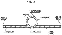
- Plural hole portions 130A are formed in the vehicle front side of an outer periphery wall of the strut main body 36, and plural hole portions 132A are formed in the vehicle rear side of the outer periphery wall.
- the hole portions 130A and 132A are formed at positions that match up in the vehicle width direction and the vehicle vertical direction.
- the pairs of hole portions 130A and 132A are formed as strut penetrating holes that penetrate through the strut.
- the number of the first penetrating holes 110A is greater than the number of the second penetrating holes 112A with the same diameter (the same shape and the same size). Therefore, a flow amount of fuel passing through the first penetrating holes 110A and flowing toward the vehicle front side is greater than a flow amount of fuel passing through the second penetrating holes 112A, and a rotary flow of fuel around the strut 34A in plan view is caused. Consequently, fuel impacting against the side walls of the fuel tank main body 20 may be reduced and the production of noise may be further suppressed.
- the separator 300A because the hole portions 130A and 132A are formed in the strut main body 36 of the strut 34A, strut penetrating holes are formed that extend in the vehicle front-and-rear direction through the interior of the strut main body 36 (a cylindrical cavity portion).
- fuel reaching the separator 300A due to rocking from the vehicle rear passes through the hole portions 130A and 132A as well as the first penetrating holes 110A and the second penetrating holes 112A, and moves toward the vehicle front side. Therefore, the flow of fuel passing through the separator 300A is fragmented and fluid energy (a flow speed) of fuel passing through the separator 300A is further reduced. Consequently, fuel that passes through the separator 300A is inhibited from impacting against the side walls of the fuel tank main body 20 and the production of noise is suppressed even further.
- a fuel tank according to a fourth exemplary embodiment of the present disclosure is described with reference to Fig. 14A and Fig. 14B .
- Structural elements that are similar to the first exemplary embodiment are assigned the same reference symbols and are not described in detail. Only the shape of the separator differs from the first exemplary embodiment. Accordingly, only corresponding portions are described.
- separators 100A and 100B of the fuel tank 10 of the first exemplary embodiment are replaced with separators 400A and 400B, which are described below.
- the separator 400A and the separator 400B have similar operational effects. Therefore, only the separator 400A is described and descriptions of the separator 400B are not given.
- reinforcing ribs 404A and 406A are provided extending from the strut main body 36 of the strut 34A to a vehicle front side face 402A of the second plate portion 104A of the separator 400A.
- the reinforcing ribs 404A and 406A have triangular shapes in plan view and are separated by a predetermined spacing in the vehicle vertical direction.
- a bending stiffness of the second plate portion 104A is higher than a bending stiffness of the first plate portion 102A.
- the first plate portion 102A that is being pushed by the fuel rocking toward the vehicle front bends toward the vehicle front side more than the second plate portion 104A.
- a flow amount of fuel flowing toward the vehicle front side in the vicinity of the first plate portion 102A is greater than a flow amount of fuel flowing toward the vehicle front side in the vicinity of the second plate portion 104A. Therefore, as shown in Fig. 5B , a flow of fuel from the first plate portion 102A toward the second plate portion 104A around the strut 34A in plan view (a rotary flow) occurs, and an amount of the fuel rocking toward the vehicle front side that impacts against the side walls of the fuel tank main body 20 is suppressed. Consequently, the production of noise is further suppressed.
- the separator 200B provides the same operational effects as the separator 200A.
- the reinforcing ribs 404A and 406A are provided only at the second plate portion 104A.
- reinforcing ribs may also be provided at the first plate portion 102A. In this case too, the same operational effects are provided as long as the bending stiffnesses of the first plate portion 102A and the second plate portion 104A are made different, by the number of reinforcing ribs being made different or the like.
- the bending stiffnesses of the first plate portion 102A and the second plate portion 104A may be made different by means other than reinforcing ribs. For example, it may be that the bending stiffnesses are made different by the shapes of the first plate portion 102A and the second plate portion 104A being made different.
- the separators 100A, 100B, 200A, 200B, 300A, 300B, 400A and 400B are provided at the strut 34A in the first storage portion 24 and the strut 44A in the second storage portion 26, but this is not limiting.
- the separators 100A to 400B may be provided at the struts 34B and 44B. Further, the separators 100A to 400B may be provided at the pairs of struts 34A, 34B, 44A and 44B.
- first plate portions 102A and 102B and second plate portions 104A and 104B of the separators 100A to 400B are formed integrally with the strut main bodies 36 and 46, but this is not limiting. That is, the separators 100A to 400B may be structured by the first plate portions 102A and 102B and second plate portions 104A and 104B being attached to the strut main bodies 36 and 46 via brackets.
- the first plate portions 102A and 102B and second plate portions 104A and 104B are formed with left-right symmetry about the separators 100A to 400B, but this is not limiting.
- non-symmetry between left and right is possible, with the areas of the second plate portions 104A and 104B being formed to be larger than the areas of the first plate portions 102A and 102B.
- first plate portions 102A and 102B and second plate portions 104A and 104B of the separators 100A to 400B extend in the vehicle width direction sandwiching the strut main bodies 36 and 46, but this is not limiting.
- first plate portions 102A and 102B and second plate portions 104A and 104B may extend in the vehicle front-and-rear direction sandwiching the strut main bodies 36 and 46.
- first plate portions 102A and 102B and second plate portions 104A and 104B are arranged in straight lines sandwiching the strut main bodies 36 and 46, but this is not limiting.
- first plate portions 102A and 102B and second plate portions 104A and 104B are provided at the struts 34A and 44A that are connected with the floor wall 12 and the upper wall 18, but this is not limiting.
- the first plate portions 102A and 102B and second plate portions 104A and 104B may be provided at struts that extend from one toward the other of the floor wall 12 and the upper wall 18 (and are not connected to the other).
- first penetrating holes 110A and second penetrating holes 112A are recited as being holes with circular shapes in cross section, but this is not limiting.
- the holes may be holes with square shapes in cross section.
Landscapes
- Engineering & Computer Science (AREA)
- Life Sciences & Earth Sciences (AREA)
- Sustainable Development (AREA)
- Sustainable Energy (AREA)
- Chemical & Material Sciences (AREA)
- Combustion & Propulsion (AREA)
- Transportation (AREA)
- Mechanical Engineering (AREA)
- Cooling, Air Intake And Gas Exhaust, And Fuel Tank Arrangements In Propulsion Units (AREA)
Abstract
Description
- The present disclosure relates to a fuel tank.
- Fuel tanks have a problem of fuel rocking within a fuel tank during acceleration or the like and noise being produced by the fuel impacting against wall faces of the tank.
- As a countermeasure, suppressing rocking of fuel within a fuel tank by disposing separators formed of plate bodies inside the fuel tank has been proposed.
- For example, a structure has been proposed (see Japanese Patent Application Laid-Open (
JP-A) No. 2015-160500 - Even when a separator is disposed inside a fuel tank as in the conventional technology described above, there is scope for improvement in regard to suppressing the production of noise.
- In consideration of the circumstances described above, the present disclosure provides a fuel tank that may further suppress the production of noise in the fuel tank.
- A fuel tank according to a first aspect of the present disclosure includes: a fuel tank main body that is enclosed by a floor wall, side walls and an upper wall, and inside which fuel is stored; and a separator including a strut provided at at least one of the floor wall or the upper wall, a first plate portion in which a first penetrating hole that penetrates in a plate thickness direction is formed, the first plate portion extending in a diametric direction from the strut, and a second plate portion in which a second penetrating hole that penetrates in a plate thickness direction is formed, the second plate portion sandwiching the strut with the first plate portion and extending in a diametric direction at an opposite side of the strut from a side thereof at which the first plate portion is disposed, wherein at least one of shapes, sizes or numbers of the first penetrating hole and the second penetrating hole is set to be different such that fluid resistances at the first plate portion and the second plate portion are different.
- This fuel tank is equipped with the separator that includes the first plate portion and the second plate portion that are provided to sandwich the strut from opposite sides of the strut. Consequently, rocking of the fuel is suppressed by the first plate portion and the second plate portion, and the production of noise in the fuel tank is suppressed.
- At least one of numbers, sizes and shapes of the first penetrating holes formed in the first plate portion and the second penetrating holes formed in the second plate portion is set to be different such that fluid resistances of the first plate portion and the second plate portion are different.
- For example, if the first penetrating holes and second penetrating holes are formed such that the fluid resistance of the second plate portion is greater than the fluid resistance of the first plate portion, then when the fuel rocks, a flow amount of fuel flowing through the first penetrating holes in the first plate portion with the smaller fluid resistance to the opposite side of the first plate portion in plan view is greater than a flow amount of fuel flowing through the second penetrating holes in the second plate portion with the larger fluid resistance to the opposite side of the second plate portion. As a result, a flow of fuel rotating from the first plate portion toward the second plate portion around the strut in plan view (below referred to as a "rotary flow") is produced. Consequently, the fuel that passes through the first penetrating holes in the first plate portion and the second penetrating holes in the second plate portion of the separator during rocking of the fuel is inhibited from approaching the side walls of the fuel tank main body. Thus, the production of noise by rocking fuel impacting against the side walls of the fuel tank main body is further suppressed.
- In a fuel tank according to a second aspect of the present disclosure, in the fuel tank of the first aspect, only the first penetrating hole in the first plate portion or the second penetrating hole in the second plate portion is formed.
- In this fuel tank, the first penetrating holes or the second penetrating holes are formed in only one of the first plate portion and the second plate portion. For example, if the first penetrating holes are formed only in the first plate portion and no second penetrating holes are formed in the second plate portion, the fluid resistance of the first plate portion in which the first penetrating holes are formed is lower than the fluid resistance of the second plate portion in which no second penetrating holes are formed. Thus, when the fuel rocks, a rotary flow of the fuel from the first plate portion toward the second plate portion around the strut in plan view is caused by the fuel passing through the first penetrating holes in the first plate portion. As a result, flows of rocking fuel toward the side walls of the fuel tank main body via the first penetrating holes may be suppressed. Thus, the production of noise in the fuel tank main body may be further suppressed.
- In a fuel tank according to a third aspect of the present disclosure, in the fuel tank of the first aspect, the first penetrating hole and the second penetrating hole are circular holes, and the first penetrating hole and the second penetrating hole differ in hole diameter.
- In this fuel tank, the hole diameters of the circular holes differ between the first penetrating holes and the second penetrating holes. For example, if the hole diameters of the first penetrating holes are greater than the hole diameters of the second penetrating holes, the fluid resistance of the first plate portion is smaller than the fluid resistance of the second plate portion. Thus, when the fuel rocks, a fuel flow amount passing through the first penetrating holes in the first plate portion is greater than a fuel flow amount passing through the second penetrating holes in the second plate portion. As a result, a rotary flow of the fuel from the first plate portion toward the second plate portion around the strut in plan view occurs and flows of rocking fuel toward the side walls of the fuel tank main body via the first penetrating holes and second penetrating holes may be suppressed. Thus, the production of noise in the fuel tank main body may be further suppressed.
- In a fuel tank according to a fourth aspect of the present disclosure, in the fuel tank of the first aspect, the first penetrating hole decreases in diameter from a face at one side of the first plate portion toward a face at another side thereof, and the second penetrating hole increases in diameter from a face at the one side of the second plate portion toward a face at the other side thereof.
- In this fuel tank, the first penetrating holes are formed with decreasing diameters from the face at the one side of the first plate portion toward the face at the other side, and the second penetrating holes are formed with increasing diameters from the face at the one side of the second plate portion toward the face at the other side. In other words, directions of taper (directions of increasing diameter) of the first penetrating holes and the second penetrating holes are opposite directions. Therefore, when a direction of rocking fuel is the direction of decreasing diameter of the first penetrating holes (the direction of increasing diameter of the second penetrating holes), an inflow amount of fuel passing through the first penetrating holes in the first plate portion is larger (a flow speed thereof is higher) and a flow amount of fuel passing through the second penetrating holes is smaller (a flow speed thereof is lower). As a result, a rotary flow of the fuel from the first plate portion toward the second plate portion around the strut in plan view occurs and amounts of rocking fuel approaching the side walls of the fuel tank main body via the first penetrating holes and second penetrating holes may be suppressed. Thus, the production of noise in the fuel tank main body may be further suppressed.
- In a fuel tank according to a fifth aspect of the present disclosure, in the fuel tank of any one of the first to fourth aspects, a strut penetrating hole is formed, the strut penetrating hole penetrating through the strut in a same direction as a direction of extension of the first penetrating hole and the second penetrating hole.
- Because strut penetrating holes are formed penetrating through the strut in the same direction as the direction of extension of the first penetrating holes in the first plate portion and the second penetrating holes in the second plate portion, a flow of fuel passing through the separator is fragmented by passing through the first penetrating holes in the first plate portion and the second penetrating holes in the second plate portion and also passing through the strut penetrating holes. Thus, a flow speed (fluid energy) of the fuel that passes through is lowered further. As a result, the production of noise by rocking fuel impacting against the side walls of the fuel tank main body is even further suppressed.
- A fuel tank according to a sixth aspect of the present disclosure includes: a fuel tank main body that is enclosed by a floor wall, side walls and an upper wall, and inside which fuel is stored; and a separator including a strut provided at at least one of the floor wall and the upper wall, a first plate portion that extends in a diametric direction from the strut, or a second plate portion that sandwiches the strut with the first plate portion and extends in a diametric direction at an opposite side of the strut from a side thereof at which the first plate portion is disposed, wherein a bending stiffness of the first plate portion is different from a bending stiffness of the second plate portion.
- This fuel tank includes the separator that includes the first plate portion and the second plate portion that are provided to sandwich the strut from opposite sides of the strut. Because the first plate portion and the second plate portion have different bending stiffnesses, when fuel is rocking in the fuel tank main body, bending deformation amounts of the first plate portion and the second plate portion are different.
- For example, if the bending stiffness of the second plate portion is higher than the bending stiffness of the first plate portion, then when the fuel rocks, a flow amount of fuel passing through the vicinity of the first plate portion whose bending deformation amount is relatively large is greater than a flow amount of fuel passing through the vicinity of the second plate portion. As a result, a flow of fuel from the first plate portion toward the second plate portion around the strut in plan view (a rotary flow) is produced.
Consequently, a flow amount of rocking fuel toward the side walls of the fuel tank main body is suppressed. Thus, the production of noise by rocking fuel impacting against the side walls of the fuel tank main body is suppressed. - In a fuel tank according to a seventh aspect of the present disclosure, in the fuel tank of the sixth aspect, a reinforcing rib is formed at at least one of the first plate portion or the second plate portion.
- In this fuel tank, because the reinforcing rib is provided at the at least one of the first plate portion and the second plate portion, the bending stiffness of the one plate portion is set to be higher than the other plate portion.
- For example, if the bending stiffness of the second plate portion is set to be higher than the bending stiffness of the first plate portion by a reinforcing rib being provided only at the second plate portion, then when the fuel rocks, a flow amount of fuel passing through the vicinity of the first plate portion whose bending deformation amount is relatively large is greater than a flow amount of fuel passing through the vicinity of the second plate portion. As a result, a flow of fuel from the first plate portion toward the second plate portion around the strut in plan view (a rotary flow) is produced. Consequently, a flow amount of rocking fuel toward the side walls of the fuel tank main body is suppressed. Thus, the production of noise by rocking fuel impacting against the side walls of the fuel tank main body is suppressed.
- In a fuel tank according to an eighth aspect of the present disclosure, in the fuel tank of any one of the first to seventh aspects, the fuel tank main body includes a first storage portion, a second storage portion and a connecting portion, each of the first storage portion and the second storage portion being enclosed by a floor wall, side walls and an upper wall and the fuel being stored thereinside, and the connecting portion putting an upper portion of the first storage portion into fluid communication with an upper portion of the second storage portion, and respective separators are disposed in the first storage portion and the second storage portion.
- in this saddle-shaped fuel tank, because the separators are provided in each of the pair of storage portions, the production of noise by fuel rocking in the storage portions impacting against the side walls of the storage portions may be suppressed effectively.
- A fuel tank according to the first to eighth aspects of the present disclosure may further suppress the production of noise with the structures described above.
- Exemplary embodiments of the present disclosure will be described in detail based on the following figures, wherein:
-
Fig. 1 is a sectional view cut along line A-A inFig. 2 ; -
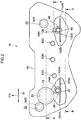
Fig. 2 is a plan view of a fuel tank according to a first exemplary embodiment of the present disclosure; -
Fig. 3 is a sectional view cut along line B-B inFig. 2 ; -
Fig. 4 is a front view of a separator according to the first exemplary embodiment of the present disclosure; -
Fig. 5A is a schematic explanatory plan view showing a noise production suppression operation of the separator according to the exemplary embodiment of the present disclosure, which is a diagram showing an initial time of fuel rocking toward the vehicle front; -
Fig. 5B is a schematic explanatory plan view showing the noise production suppression operation of the separator according to the exemplary embodiment of the present disclosure, which is a diagram showing a time after a predetermined duration has passed from the initial time of the fuel rocking toward the vehicle front; -
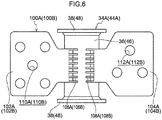
Fig. 6 is a front view of a separator according to a variation of the first exemplary embodiment of the present disclosure; -
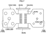
Fig. 7 is a front view of a separator according to another variation of the first exemplary embodiment of the present disclosure; -
Fig. 8 is a front view of a separator according to still another variation of the first exemplary embodiment of the present disclosure; -
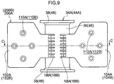
Fig. 9 is a front view of a separator according to a second exemplary embodiment of the present disclosure; -
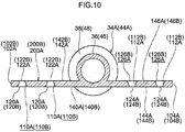
Fig. 10 is a sectional view cut along line C-C inFig. 9 ; -
Fig. 11 is a schematic sectional enlarged diagram showing flow states at a separator according to a third exemplary embodiment of the present disclosure, in which (1) is a diagram showing a first penetrating hole and (2) is a diagram showing a second penetrating hole; -
Fig. 12 is a front view of the separator according to the third exemplary embodiment of the present disclosure; -
Fig. 13 is a sectional view cut along line D-D inFig. 12 ; -
Fig. 14A is a front view of a separator according to a fourth exemplary embodiment of the present disclosure; and -
Fig. 14B is a sectional view cut along line E-E inFig. 14A . - A fuel tank according to a first exemplary embodiment of the present disclosure is described with reference to
Fig. 1 to Fig. 8 . In the following descriptions, the arrow FR in the drawings indicates the vehicle front, the arrow UP indicates the vehicle upper side, and the arrow W indicates the vehicle width direction. - First, overall structure of a
fuel tank 10 is described with reference toFig. 1 . Thefuel tank 10 includes a fuel tankmain body 20 that is provided with afloor wall 12, aleft wall 14, aright wall 16 and anupper wall 18. Thefloor wall 12 extends in the vehicle width direction, Theleft wall 14 andright wall 16 extend to the vehicle upper side from two vehicle width direction end portions of thefloor wall 12. Theupper wall 18 extends in the vehicle width direction, linking between upper ends of theleft wall 14 andright wall 16. The fuel tankmain body 20 is closed up by thefloor wall 12, side walls including theleft wall 14 andright wall 16, and theupper wall 18. The fuel tankmain body 20 is capable of storing fuel thereinside. - A vehicle width direction central portion of the
floor wall 12 includes abump portion 22 that is recessed toward the vehicle upper side in order to avoid adriveshaft 19 andexhaust pipe 21 of the vehicle. That is, thefuel tank 10 is a "saddle-shaped" fuel tank. Thefuel tank 10 is a resin fuel tank formed of resin. Thedriveshaft 19 andexhaust pipe 21 are shown only inFig. 1 and are not shown in the other drawings. - The interior of the fuel tank
main body 20 is divided into afirst storage portion 24 disposed at the vehicle width direction left side relative to thebump portion 22, asecond storage portion 26 disposed at the vehicle width direction right side, and a connectingportion 28. The connectingportion 28 connects (puts into fluid communication) upper portions of thefirst storage portion 24 andsecond storage portion 26 with one another. - Portions of the
floor wall 12 andupper wall 18 that structure thefirst storage portion 24 are referred to as, respectively, a firstfloor wall portion 12A and a firstupper wall portion 18A. Portions of thefloor wall 12 andupper wall 18 that structure thesecond storage portion 26 are referred to as, respectively, a secondfloor wall portion 12B and a secondupper wall portion 18B. Portions of thefloor wall 12 andupper wall 18 that structure the connectingportion 28 are referred to as, respectively, a thirdfloor wall portion 12C and a thirdupper wall portion 18C. - As shown in
Fig. 2 , astrut 34A and a strut 34B are disposed in thefirst storage portion 24 to extend in the vehicle vertical direction. Thestrut 34A and strut 34B are disposed to sandwich anattachment hole portion 64, which is described below, from, respectively, a vehicle rear side and a vehicle front side thereof. - As shown in
Fig. 3 , anattachment portion 30 that protrudes toward the vehicle upper side is formed at a strut arrangement position of the firstfloor wall portion 12A, and anattachment portion 32 that protrudes toward the vehicle lower side is formed at a strut arrangement position of the firstupper wall portion 18A. Thestrut 34A extending in the vehicle vertical direction is disposed between theattachment portions - As shown in
Fig. 4 , thestrut 34A includes a strutmain body 36 in a substantially circular tube shape andflange portions 38, which are formed to protrude to diametric direction outer sides at both of end portions of the strutmain body 36. Thestrut 34A is disposed between the firstupper wall portion 18A and the firstfloor wall portion 12A by theflange portions 38 being joined to thecorresponding attachment portions - A
separator 100A is provided at thestrut 34A. As shown inFig. 3 andFig. 4 , theseparator 100A includes afirst plate portion 102A and asecond plate portion 104A. Thefirst plate portion 102A is provided to extend to the vehicle width direction outer side from thestrut 34A. Thesecond plate portion 104A is provided to extend to the vehicle width direction inner side from thestrut 34A. As shown inFig. 4 , thefirst plate portion 102A andsecond plate portion 104A are connected to the vehicle rear side of an outer periphery surface of thestrut 34A via, respectively,ribs 106A andribs 108A. That is, thefirst plate portion 102A andsecond plate portion 104A are provided to sandwich thestrut 34A with left-right symmetry in the vehicle width direction. Here, thefirst plate portion 102A andsecond plate portion 104A are formed integrally with thestrut 34A. - The
first plate portion 102A andsecond plate portion 104A are formed with the same areas and shapes, except for being left-right symmetrical and including first penetratingholes 110A and second penetratingholes 112A, which are described below. - Five of the first penetrating
holes 110A are formed in thefirst plate portion 102A, extending in the vehicle front-and-rear direction (the plate thickness direction). Three of the second penetratingholes 112A are formed in thesecond plate portion 104A, extending in the vehicle front-and-rear direction (the plate thickness direction). Diameters of the second penetratingholes 112A are set to be smaller than diameters of the first penetratingholes 110A. Thus, a cross-sectional area of the second penetratingholes 112A is set to be smaller than a cross-sectional area of the first penetratingholes 110A. - The strut 34B has a similar structure to the
strut 34A, except for no separator being provided thereat. - Similarly to the
first storage portion 24, as shown inFig. 2 , a pair ofstruts second storage portion 26. As shown inFig. 3 , thestrut 44A, similarly to thestrut 34A, includes a strutmain body 46 in a substantially circular tube shape andflange portions 48 that are formed to protrude to diametric direction outer sides at both of end portions of the strutmain body 46. Thestrut 44A is disposed between the secondupper wall portion 18B and secondfloor wall portion 12B by theflange portions 48 being joined to, respectively,attachment portions - A
separator 100B is provided at thestrut 44A. Theseparator 100B has substantially the same structure as theseparator 100A. Therefore, reference symbols are the same as the reference symbols of structural members of theseparator 100A are assigned, with the suffix "B", and detailed descriptions are not given here (seeFig. 3 andFig. 4 ). - The
strut 44B disposed at the vehicle front side of thestrut 44A has a similar structure to thestrut 44A, except for no separator being provided. - As shown in
Fig. 2 , stand-offs portion 28. At the stand-offs 62A to 62C, truncated cone-shaped projection portions that are formed to project toward the vehicle upper side from the thirdfloor wall portion 12C are joined to truncated cone-shaped projection portions that are formed to project toward the vehicle lower side from the thirdupper wall portion 18C. Thus, the three stand-offs 62A to 62C are formed in the connectingportion 28 at predetermined spacings in the vehicle width direction. - As shown in
Fig. 1 , theattachment hole portion 64 is formed in the firstupper wall portion 18A of thefirst storage portion 24 for attachment of internal components of thefuel tank 10 to the interior of the fuel tankmain body 20. - The
attachment hole portion 64 is formed a little to the vehicle front side of the middle of the firstupper wall portion 18A. As shown inFig. 1 , theattachment hole portion 64 includes a circular tube-shapedsupport portion 68 and an insert ring 66 fabricated of metal, which is insert-molded in thesupport portion 68. - As shown in
Fig. 1 , theattachment hole portion 64 is closed off by alid body 74 being placed on the insert ring 66 and fastened to the insert ring 66 by a metal fixture that is not shown in the drawings. - As shown in
Fig. 1 , apump module 80 is disposed in thefirst storage portion 24 below theattachment hole portion 64. - The
pump module 80 is provided with afuel pump 84 and afilter 86 inside a sub-cap 82. Thefuel pump 84 supplies fuel to outside the fuel tankmain body 20. Thefilter 86 removes foreign substances from fuel that is sucked into thefuel pump 84. Afuel supply tube 88 of thepump module 80 supplies fuel to outside the fuel tankmain body 20. Thefuel supply tube 88 extends from thefuel pump 84 to the outside, penetrating through thelid body 74. - A jet pump, which is not shown in the drawings, is provided inside the
pump module 80. The jet pump is for sucking fuel from thesecond storage portion 26 side through afuel transfer pipe 90. An end portion of thefuel transfer pipe 90 is connected to the jet pump. - As shown in
Fig. 1 , abracket 92 is attached to thestrut 44B at the vehicle front side of thesecond storage portion 26. Afilter portion 96 is disposed at a distal end of anarm 94 that extends toward the secondfloor wall portion 12B from thebracket 92. One end of thefuel transfer pipe 90 for supplying fuel from thesecond storage portion 26 to thepump module 80 in thefirst storage portion 24 is connected to thefilter portion 96. As shown inFig. 2 , thefilter portion 96 is disposed on the secondfloor wall portion 12B of thesecond storage portion 26 between the pair ofstruts - As shown in
Fig. 1 , thefuel transfer pipe 90 connects (puts into fluid communication) thefilter portion 96 with the pump module 80 (the jet pump). - First, operation of the
fuel tank 10 according to the first exemplary embodiment is described. Theseparator 100A and theseparator 100B have similar operational effects. Therefore, only theseparator 100A is described and descriptions of theseparator 100B are not given. - In the
fuel tank 10, because theseparator 100A is disposed in thefirst storage portion 24, rocking of fuel toward the vehicle front side in thefirst storage portion 24, for example, during deceleration or the like is suppressed by thefirst plate portion 102A and thesecond plate portion 104A. As a result, the production of noise by the rocking fuel impacting against the side walls of the fuel tankmain body 20 is suppressed. - Although the
first plate portion 102A and thesecond plate portion 104A have the same shapes (and same areas) with left-right symmetry, five of the first penetratingholes 110A are formed in thefirst plate portion 102A and three of the second penetratingholes 112A are formed in thesecond plate portion 104A. In addition, the diameters of the first penetratingholes 110A are larger than the diameters of the second penetratingholes 112A. Thus, a fluid resistance of thesecond plate portion 104A is set to be greater than a fluid resistance of thefirst plate portion 102A. - Therefore, as is schematically shown in
Fig. 5A , a flow amount of rocking fuel passing through the first penetratingholes 110A in thefirst plate portion 102A (see arrow P) of theseparator 100A is greater than a flow amount of rocking fuel passing through the second penetratingholes 112A in thesecond plate portion 104A (see arrow Q). - As a result, a flow of fuel rotating from the
first plate portion 102A toward thesecond plate portion 104A around thestrut 34A in plan view (below referred to as a "rotary flow") occurs (see arrow R inFig. 5B ). - Consequently, a large proportion of the rocking fuel passing through the first penetrating
holes 110A in thefirst plate portion 102A and the second penetratingholes 112A in thesecond plate portion 104A does not impact against the side walls of the fuel tankmain body 20. That is, only a portion of the rocking fuel passing through the first penetratingholes 110A and the second penetratingholes 112A impacts against the side walls of the fuel tankmain body 20. As a result, the production of noise in thefuel tank 10 is even further suppressed. - As shown in
Fig. 5B , this rotary flow reaches thesecond plate portion 104A in the opposite direction (toward the vehicle rear) to the rocking direction of the fuel (toward the vehicle front). Therefore, deformation of theseparator 100A (thesecond plate portion 104A) by the rocking of the fuel may be suppressed. - The
separator 100A is formed by thefirst plate portion 102A and thesecond plate portion 104A being provided at thestrut 34A, and thestrut 34A is connected with the firstupper wall portion 18A and the firstfloor wall portion 12A. Thus, deformation of thefuel tank 10 fabricated of resin, particularly of the firstupper wall portion 18A and the firstfloor wall portion 12A, is suppressed. In other words, because thefirst plate portion 102A andsecond plate portion 104A of theseparator 100A are provided at thestrut 34A that suppresses deformation, a number of components may be reduced. - Because the
first storage portion 24 and thesecond storage portion 26 are divided apart in the saddle-shapedfuel tank 10, when a remaining fuel amount is small, the fuel rocks separately in thefirst storage portion 24 and thesecond storage portion 26. Because theseparators first storage portion 24 and thesecond storage portion 26 of thefuel tank 10, rocking of fuel is suppressed in each of thefirst storage portion 24 and thesecond storage portion 26. Moreover, rotary flows around thestruts holes holes main body 20 may be suppressed. Thus, the production of noise in thefuel tank 10 may be suppressed effectively. - In the present exemplary embodiment, a difference in fuel flow amounts passing through the first penetrating
holes 110A and second penetratingholes 112A in thefirst plate portion 102A andsecond plate portion 104A of theseparator 100A is produced by varying the numbers and diameters (sizes) of the first penetratingholes 110A and the second penetratingholes 112A. However, this is not limiting. - For example, as shown in
Fig. 6 , it may be that the numbers of the first penetratingholes 110A and the second penetratingholes 112A are different but the diameters are the same. Alternatively, as shown inFig. 7 , it may be that the diameters of the first penetratingholes 110A and the second penetratingholes 112A are different but the numbers are the same. - In these structures too, a fuel flow amount passing through the first penetrating
holes 110A is larger than a fuel flow amount passing through the second penetratingholes 112A, and the production of noise may be further suppressed by a rotary flow being caused around thestrut 34A in plan view. - Further, at least one of the numbers and diameters of the first penetrating
holes 110A and the second penetratingholes 112A being different encompasses the number or diameter of the first penetratingholes 110A or the second penetratingholes 112A being zero. For example, as shown inFig. 8 , this encompasses the first penetratingholes 110A being formed in thefirst plate portion 102A but no second penetrating holes being formed in thesecond plate portion 104A. In this case too, fuel only passes through the first penetratingholes 110A at thefirst plate portion 102A side and flows to the vehicle front side, a rotary flow around thestrut 34A in plan view is caused, and the production of noise may be further suppressed. - A fuel tank according to a second exemplary embodiment of the present disclosure is described with reference to
Fig. 9 to Fig. 11 . Structural elements that are similar to the first exemplary embodiment are assigned the same reference symbols and are not described in detail. Only the shape of the separator differs from the first exemplary embodiment. Accordingly, only corresponding portions are described. - In a fuel tank according to the second exemplary embodiment (not shown in the drawings), the
separators fuel tank 10 according to the first exemplary embodiment are replaced withseparators - Operational effects of the
separator 200A and theseparator 200B are similar. Therefore, only theseparator 200A is described and descriptions of theseparator 200B are not given. - As shown in
Fig. 9 , four each of the first penetratingholes 110A and the second penetratingholes 112A are formed in, respectively, thefirst plate portion 102A and thesecond plate portion 104A of theseparator 200A. - As shown in
Fig. 10 , the first penetratingholes 110A are formed in tapered shapes that decrease in diameter toward the vehicle front, such that vehicle rear side end portions of the first penetratingholes 110A that open in afirst face 140A at the vehicle rear side of thefirst plate portion 102A arelarge diameter portions 120A and vehicle front side end portions of the first penetratingholes 110A that open in asecond face 142A at the vehicle front side of thefirst plate portion 102A aresmall diameter portions 122A. - Meanwhile, the second penetrating
holes 112A are formed in tapered shapes that increase in diameter toward the vehicle front, such that vehicle rear side end portions of the second penetratingholes 112A that open in afirst face 144A at the vehicle rear side of thesecond plate portion 104A aresmall diameter portions 124A and vehicle front side end portions of the second penetratingholes 112A that open in asecond face 146A at the vehicle front side of thesecond plate portion 104A arelarge diameter portions 126A. - That is, the first penetrating
holes 110A and second penetratingholes 112A are formed in tapered shapes that are the same shapes but tapered in opposite directions. - When fuel inside the fuel tank
main body 20 rocks toward the vehicle front due to the vehicle decelerating, rocking of the fuel in thefirst storage portion 24 is suppressed by thefirst plate portion 102A andsecond plate portion 104A of theseparator 200A, and the production of noise is suppressed. - As shown in (1) of
Fig. 11 , because the vehicle rear side end portions of the first penetratingholes 110A of thefirst plate portion 102A are formed as thelarge diameter portions 120A, large amounts of fuel flow into the first penetratingholes 110A, and because the diameters decrease toward the vehicle front, the fuel is ejected from the first penetratingholes 110A with a raised flow speed. - In contrast, as shown in (2) of
Fig. 11 , because the vehicle rear side end portions of the second penetratingholes 112A of thesecond plate portion 104A are formed as thesmall diameter portions 124A with smaller diameters than thelarge diameter portions 120A, smaller amounts of fuel flow into the second penetratingholes 112A, and because the diameters of the second penetratingholes 112A increase toward the vehicle front, the flow speed of the fuel is lowered. - Therefore, as is schematically shown in
Fig. 5A , a flow amount of rocking fuel passing through the first penetratingholes 110A in thefirst plate portion 102A (see arrow P) of theseparator 100A is greater than a flow amount of rocking fuel passing through the second penetratingholes 112A in thesecond plate portion 104A (see arrow Q). - As a result, a rotary flow of fuel rotating from the
first plate portion 102A toward thesecond plate portion 104A around thestrut 34A in plan view occurs (see arrow R inFig. 5B ). - Consequently, a large proportion of the rocking fuel passing through the first penetrating
holes 110A in thefirst plate portion 102A and the second penetratingholes 112A in thesecond plate portion 104A does not impact against the side walls of the fuel tankmain body 20. That is, only a portion of the rocking fuel passing through the first penetratingholes 110A and the second penetratingholes 112A impacts against the side walls of the fuel tankmain body 20. As a result, the production of noise in thefuel tank 10 is even further suppressed. - In the
separator 200A according to the present exemplary embodiment too, the numbers and diameters (sizes) of the first penetratingholes 110A and second penetratingholes 112A in thefirst plate portion 102A andsecond plate portion 104A may be varied. That is, the number of the first penetratingholes 110A may be made greater than the number of the second penetratingholes 112A, the diameters of the first penetratingholes 110A may be made greater than the diameters of the second penetratingholes 112A, or the like. - A fuel tank according to a third exemplary embodiment of the present disclosure is described with reference to
Fig. 12 andFig. 13 . Structural elements that are similar to the first exemplary embodiment are assigned the same reference symbols and are not described in detail. Only the shape of the separator differs from the first exemplary embodiment. Accordingly, only corresponding portions are described. - In a fuel tank according to the third exemplary embodiment (not shown in the drawings), the
separators fuel tank 10 of the first exemplary embodiment are replaced with separators 300A and 300B, which are described below. - The separator 300A and the separator 300B have similar operational effects. Therefore, only the separator 300A is described and descriptions of the separator 300B are not given.
- As shown in
Fig. 12 , four of the first penetratingholes 110A are formed in thefirst plate portion 102A and two of the second penetratingholes 112A are formed in thesecond plate portion 104A of the separator 300A. The first penetratingholes 110A and the second penetratingholes 112A have the same diameters (and the same shapes). - As shown in
Fig. 13 , the strutmain body 36 of thestrut 34A has a substantially circular tube shape.Plural hole portions 130A are formed in the vehicle front side of an outer periphery wall of the strutmain body 36, andplural hole portions 132A are formed in the vehicle rear side of the outer periphery wall. - The
hole portions hole portions - At the separator 300A, when fuel in the fuel tank rocks toward the vehicle front due to a deceleration of the vehicle, rocking of the fuel in the
first storage portion 24 is suppressed by thefirst plate portion 102A and thesecond plate portion 104A. As a result, the production of noise by the rocking fuel impacting against the side walls of the fuel tankmain body 20 is suppressed. - In the
first plate portion 102A and thesecond plate portion 104A, the number of the first penetratingholes 110A is greater than the number of the second penetratingholes 112A with the same diameter (the same shape and the same size). Therefore, a flow amount of fuel passing through the first penetratingholes 110A and flowing toward the vehicle front side is greater than a flow amount of fuel passing through the second penetratingholes 112A, and a rotary flow of fuel around thestrut 34A in plan view is caused. Consequently, fuel impacting against the side walls of the fuel tankmain body 20 may be reduced and the production of noise may be further suppressed. - Furthermore, in the separator 300A, because the
hole portions main body 36 of thestrut 34A, strut penetrating holes are formed that extend in the vehicle front-and-rear direction through the interior of the strut main body 36 (a cylindrical cavity portion). Thus, fuel reaching the separator 300A due to rocking from the vehicle rear passes through thehole portions holes 110A and the second penetratingholes 112A, and moves toward the vehicle front side. Therefore, the flow of fuel passing through the separator 300A is fragmented and fluid energy (a flow speed) of fuel passing through the separator 300A is further reduced. Consequently, fuel that passes through the separator 300A is inhibited from impacting against the side walls of the fuel tankmain body 20 and the production of noise is suppressed even further. - A fuel tank according to a fourth exemplary embodiment of the present disclosure is described with reference to
Fig. 14A and Fig. 14B . Structural elements that are similar to the first exemplary embodiment are assigned the same reference symbols and are not described in detail. Only the shape of the separator differs from the first exemplary embodiment. Accordingly, only corresponding portions are described. - In a fuel tank according to the fourth exemplary embodiment (not shown in the drawings), the
separators fuel tank 10 of the first exemplary embodiment are replaced withseparators - The
separator 400A and theseparator 400B have similar operational effects. Therefore, only theseparator 400A is described and descriptions of theseparator 400B are not given. - As shown in
Fig. 14A and Fig. 14B , reinforcingribs main body 36 of thestrut 34A to a vehiclefront side face 402A of thesecond plate portion 104A of theseparator 400A. The reinforcingribs - In the
separator 400A with the structure described above, because the reinforcingribs second plate portion 104A, a bending stiffness of thesecond plate portion 104A is higher than a bending stiffness of thefirst plate portion 102A. - When the fuel in the fuel tank
main body 20 rocks toward the vehicle front during a deceleration of the vehicle or the like, thefirst plate portion 102A that is being pushed by the fuel rocking toward the vehicle front bends toward the vehicle front side more than thesecond plate portion 104A. - As a result, as shown in
Fig. 5A , a flow amount of fuel flowing toward the vehicle front side in the vicinity of thefirst plate portion 102A is greater than a flow amount of fuel flowing toward the vehicle front side in the vicinity of thesecond plate portion 104A. Therefore, as shown inFig. 5B , a flow of fuel from thefirst plate portion 102A toward thesecond plate portion 104A around thestrut 34A in plan view (a rotary flow) occurs, and an amount of the fuel rocking toward the vehicle front side that impacts against the side walls of the fuel tankmain body 20 is suppressed. Consequently, the production of noise is further suppressed. - The
separator 200B provides the same operational effects as theseparator 200A. - In the present exemplary embodiment, the reinforcing
ribs second plate portion 104A. However, reinforcing ribs may also be provided at thefirst plate portion 102A. In this case too, the same operational effects are provided as long as the bending stiffnesses of thefirst plate portion 102A and thesecond plate portion 104A are made different, by the number of reinforcing ribs being made different or the like. - The bending stiffnesses of the
first plate portion 102A and thesecond plate portion 104A may be made different by means other than reinforcing ribs. For example, it may be that the bending stiffnesses are made different by the shapes of thefirst plate portion 102A and thesecond plate portion 104A being made different. - In the
fuel tank 10 according to these exemplary embodiments, theseparators separators 100A to 400B) are provided at thestrut 34A in thefirst storage portion 24 and thestrut 44A in thesecond storage portion 26, but this is not limiting. Theseparators 100A to 400B may be provided at thestruts 34B and 44B. Further, theseparators 100A to 400B may be provided at the pairs ofstruts - In these exemplary embodiments, structures are described in which the
first plate portions second plate portions separators 100A to 400B are formed integrally with the strutmain bodies separators 100A to 400B may be structured by thefirst plate portions second plate portions main bodies - In these exemplary embodiments, the
first plate portions second plate portions separators 100A to 400B, but this is not limiting. For example, non-symmetry between left and right is possible, with the areas of thesecond plate portions first plate portions - In these exemplary embodiments, the
first plate portions second plate portions separators 100A to 400B extend in the vehicle width direction sandwiching the strutmain bodies first plate portions second plate portions main bodies - It is preferable if the
first plate portions second plate portions main bodies - In these exemplary embodiments, the
first plate portions second plate portions struts floor wall 12 and theupper wall 18, but this is not limiting. Thefirst plate portions second plate portions floor wall 12 and the upper wall 18 (and are not connected to the other). - In these exemplary embodiments, the first penetrating
holes 110A and second penetratingholes 112A are recited as being holes with circular shapes in cross section, but this is not limiting. For example, the holes may be holes with square shapes in cross section. - Plural exemplary embodiments among the first to fourth exemplary embodiments may be employed in combination.
Claims (8)
- A fuel tank comprising:a fuel tank main body (20) that is enclosed by a floor wall (12), side walls (14, 16) and an upper wall (18), and inside which fuel is stored; anda separator (100A, 100B) includingwherein at least one of shapes, sizes or numbers of the first penetrating hole and the second penetrating hole is set to be different such that fluid resistances at the first plate portion and the second plate portion are different.a strut (33A, 44A) provided at at least one of the floor wall or the upper wall,a first plate portion (102A, 102B) in which a first penetrating hole (110A, 110B) that penetrates in a plate thickness direction is formed, the first plate portion extending in a diametric direction from the strut, anda second plate portion (104A, 104B) in which a second penetrating hole (112A, 112B) that penetrates in a plate thickness direction is formed, the second plate portion sandwiching the strut with the first plate portion and extending in a diametric direction at an opposite side of the strut from a side thereof at which the first plate portion is disposed,
- The fuel tank according to claim 1, wherein only the first penetrating hole (110A, 110B) in the first plate portion (102A, 102B) or the second penetrating hole (112A, 112B) in the second plate portion (104A, 104B) is formed.
- The fuel tank according to claim 1, wherein the first penetrating hole (110A, 110B) and the second penetrating hole (112A, 112B) are circular holes, and the first penetrating hole and the second penetrating hole differ in hole diameter.
- The fuel tank according to claim 1, wherein:the first penetrating hole (110A, 110B) decreases in diameter from a face at one side of the first plate portion toward a face at another side thereof; andthe second penetrating hole (112A, 112B) increases in diameter from a face at the one side of the second plate portion toward a face at the other side thereof.
- The fuel tank according to any one of claims 1 to 4, wherein a strut penetrating hole (130A, 132A) is formed in the strut (33A, 44A), the strut penetrating hole penetrating through the strut in a same direction as a direction of extension of the first penetrating hole and the second penetrating hole.
- A fuel tank comprising:a fuel tank main body (20) that is enclosed by a floor wall, side walls and an upper wall, and inside which fuel is stored; anda separator (400A, 400B) includinga strut provided at at least one of the floor wall or the upper wall,a first plate portion that extends in a diametric direction from the strut, anda second plate portion that sandwiches the strut with the first plate portion and extends in a diametric direction at an opposite side of the strut from a side thereof at which the first plate portion is disposed,wherein a bending stiffness of the first plate portion is different from a bending stiffness of the second plate portion.
- The fuel tank according to claim 6, wherein a reinforcing rib (404A, 406A) is formed at at least one of the first plate portion or the second plate portion.
- The fuel tank according to any one of claims 1 to 7, wherein:the fuel tank main body includes a first storage portion (24), a second storage portion (26) and a connecting portion (28), each of the first storage portion and the second storage portion being enclosed by a floor wall, side walls and an upper wall and the fuel being stored thereinside, and the connecting portion putting an upper portion of the first storage portion into fluid communication with an upper portion of the second storage portion; andrespective separators are disposed in the first storage portion and the second storage portion.
Applications Claiming Priority (1)
| Application Number | Priority Date | Filing Date | Title |
|---|---|---|---|
| JP2017207282A JP6923418B2 (en) | 2017-10-26 | 2017-10-26 | Fuel tank |
Publications (2)
| Publication Number | Publication Date |
|---|---|
| EP3476642A1 true EP3476642A1 (en) | 2019-05-01 |
| EP3476642B1 EP3476642B1 (en) | 2020-06-24 |
Family
ID=63965459
Family Applications (1)
| Application Number | Title | Priority Date | Filing Date |
|---|---|---|---|
| EP18202220.2A Active EP3476642B1 (en) | 2017-10-26 | 2018-10-24 | Fuel tank |
Country Status (4)
| Country | Link |
|---|---|
| US (1) | US10919383B2 (en) |
| EP (1) | EP3476642B1 (en) |
| JP (1) | JP6923418B2 (en) |
| CN (1) | CN109703356B (en) |
Families Citing this family (3)
| Publication number | Priority date | Publication date | Assignee | Title |
|---|---|---|---|---|
| JP7037247B2 (en) * | 2018-02-22 | 2022-03-16 | 本田技研工業株式会社 | Fuel tank |
| US10851747B2 (en) * | 2018-07-24 | 2020-12-01 | Toyoda Gosei Co., Ltd. | Mounting structure of fuel device |
| JP7307367B2 (en) * | 2019-06-12 | 2023-07-12 | 日本製鉄株式会社 | fuel tank |
Citations (4)
| Publication number | Priority date | Publication date | Assignee | Title |
|---|---|---|---|---|
| EP2321139A1 (en) * | 2008-09-01 | 2011-05-18 | Inergy Automotive Systems Research (Société Anonyme) | Plastic fuel tank comprising a noise reduction baffle and process for manufacturing it |
| KR101512932B1 (en) * | 2014-02-25 | 2015-04-16 | 주식회사 동희산업 | Baffle Assembly |
| JP2015160500A (en) | 2014-02-27 | 2015-09-07 | 株式会社Fts | Separator attachment method of vehicle fuel tank |
| US20160001651A1 (en) * | 2013-02-27 | 2016-01-07 | Kautex Textron Gmbh & Co. Kg | Fuel container |
Family Cites Families (28)
| Publication number | Priority date | Publication date | Assignee | Title |
|---|---|---|---|---|
| JPH11348581A (en) * | 1998-06-12 | 1999-12-21 | Fuji Heavy Ind Ltd | Fuel tank |
| US6138859A (en) | 1999-06-08 | 2000-10-31 | Delphi Technologies, Inc. | Fuel tank assembly |
| US7455190B2 (en) | 2004-11-15 | 2008-11-25 | Automotive Components Holdings, Llc | Fuel tank system having enhanced durability and reduced permeation |
| JP2006207446A (en) | 2005-01-27 | 2006-08-10 | Toyota Motor Corp | Separator structure in the fuel tank |
| DE102009036911B4 (en) | 2009-08-11 | 2016-03-03 | Magna Steyr Fuel Systems Gmbh | Fuel tank for motor vehicles with tie rods |
| DE102010032278A1 (en) * | 2010-07-26 | 2012-01-26 | Kautex Textron Gmbh & Co. Kg | Fuel tank made of thermoplastic material |
| JP2012187754A (en) * | 2011-03-09 | 2012-10-04 | Yachiyo Industry Co Ltd | Structure and method for clamping built-in component in hollow container |
| DE102011015049B4 (en) | 2011-03-24 | 2015-09-10 | Kautex Textron Gmbh & Co. Kg | Fuel tank made of thermoplastic material for a motor vehicle and method for producing a fuel tank |
| EP2511068A1 (en) | 2011-04-12 | 2012-10-17 | Inergy Automotive Systems Research (Société Anonyme) | Process for manufacturing a plastic fuel tank |
| KR20140022412A (en) | 2011-04-12 | 2014-02-24 | 이너지 오토모티브 시스템즈 리서치 (소시에떼 아노님) | Fuel tank with improved mechanical resistance |
| DE102011117999B4 (en) | 2011-11-09 | 2013-06-13 | Kautex Textron Gmbh & Co. Kg | Container for a motor vehicle, in particular fuel or auxiliary fluid container for a motor vehicle and method for producing such a container |
| DE102012009157B4 (en) | 2012-05-08 | 2015-07-23 | Daimler Ag | Fuel storage device with a Zugankerinnenraum having a tie rod |
| JP2014024380A (en) * | 2012-07-25 | 2014-02-06 | Mitsubishi Motors Corp | Vehicle fuel tank |
| DE102012019334A1 (en) | 2012-10-02 | 2014-04-03 | Kautex Textron Gmbh & Co. Kg | Container made of thermoplastic material |
| US8991637B2 (en) | 2013-01-15 | 2015-03-31 | Ti Automotive Technology Center Gmbh | Molded reservoir support structure coupling |
| DE102013003247A1 (en) | 2013-02-27 | 2014-09-11 | Kautex Textron Gmbh & Co. Kg | Fuel tank |
| CN203449927U (en) * | 2013-08-02 | 2014-02-26 | 上海通用汽车有限公司 | Internally-arranged automobile fuel tank washboard, automobile fuel tank and automobile |
| EP2845761A1 (en) | 2013-09-06 | 2015-03-11 | Inergy Automotive Systems Research (Société Anonyme) | Tank with internal connecting member and method for assembling such a tank |
| CN203485754U (en) * | 2013-10-17 | 2014-03-19 | 亚普汽车部件股份有限公司 | Low-stress breakwater device |
| JP6235869B2 (en) * | 2013-11-01 | 2017-11-22 | 八千代工業株式会社 | Wave plate fixing structure in fuel tank |
| JP6354136B2 (en) * | 2013-11-18 | 2018-07-11 | 三菱自動車工業株式会社 | Fuel tank |
| JP2015160499A (en) | 2014-02-27 | 2015-09-07 | 株式会社Fts | Separator attachment structure of vehicle fuel tank |
| US20160076666A1 (en) * | 2014-09-16 | 2016-03-17 | GM Global Technology Operations LLC | Fuel tank valve |
| JP2016064786A (en) * | 2014-09-25 | 2016-04-28 | 本田技研工業株式会社 | Wave breaker |
| DE102014222145B4 (en) * | 2014-10-30 | 2025-01-16 | Volkswagen Aktiengesellschaft | fuel tank for a motor vehicle |
| CN204249813U (en) | 2014-11-07 | 2015-04-08 | 亚普汽车部件股份有限公司 | A kind of have flexible high pressure fuel case supporting construction |
| CN205112998U (en) * | 2015-11-27 | 2016-03-30 | 长城汽车股份有限公司 | A washboard and fuel tank for in box |
| CN206336127U (en) * | 2016-12-28 | 2017-07-18 | 芜湖顺荣汽车部件有限公司 | Wave resistance panel assembly built in fuel tank |
-
2017
- 2017-10-26 JP JP2017207282A patent/JP6923418B2/en not_active Expired - Fee Related
-
2018
- 2018-10-17 US US16/162,561 patent/US10919383B2/en not_active Expired - Fee Related
- 2018-10-18 CN CN201811214575.8A patent/CN109703356B/en not_active Expired - Fee Related
- 2018-10-24 EP EP18202220.2A patent/EP3476642B1/en active Active
Patent Citations (4)
| Publication number | Priority date | Publication date | Assignee | Title |
|---|---|---|---|---|
| EP2321139A1 (en) * | 2008-09-01 | 2011-05-18 | Inergy Automotive Systems Research (Société Anonyme) | Plastic fuel tank comprising a noise reduction baffle and process for manufacturing it |
| US20160001651A1 (en) * | 2013-02-27 | 2016-01-07 | Kautex Textron Gmbh & Co. Kg | Fuel container |
| KR101512932B1 (en) * | 2014-02-25 | 2015-04-16 | 주식회사 동희산업 | Baffle Assembly |
| JP2015160500A (en) | 2014-02-27 | 2015-09-07 | 株式会社Fts | Separator attachment method of vehicle fuel tank |
Also Published As
| Publication number | Publication date |
|---|---|
| CN109703356B (en) | 2022-01-04 |
| EP3476642B1 (en) | 2020-06-24 |
| US10919383B2 (en) | 2021-02-16 |
| JP2019077387A (en) | 2019-05-23 |
| JP6923418B2 (en) | 2021-08-18 |
| US20190126745A1 (en) | 2019-05-02 |
| CN109703356A (en) | 2019-05-03 |
Similar Documents
| Publication | Publication Date | Title |
|---|---|---|
| EP3476642B1 (en) | Fuel tank | |
| EP3074297B1 (en) | Vehicle rear portion structure | |
| EP3034823B1 (en) | Oil mist separator | |
| JP2017006831A (en) | Return filter | |
| EP2837519B1 (en) | Vehicle fuel tank | |
| EP3173273A1 (en) | Vehicle body structure | |
| JP5365660B2 (en) | Vehicle lower structure | |
| JP2007106317A (en) | tank | |
| JP5973715B2 (en) | water pump | |
| KR102286846B1 (en) | Baffle assembly of tank | |
| CN104806581B (en) | A kind of automotive steering reservoir | |
| JP5887904B2 (en) | Reserve tank for vehicles | |
| CN100410523C (en) | Fuel filling equipment for construction machinery | |
| JP6608399B2 (en) | Construction machinery | |
| JP4307278B2 (en) | Oil tank and moving body | |
| JP6094529B2 (en) | Structure of the lower rear of the car | |
| JP5980605B2 (en) | In-vehicle water tank and fire engine equipped with in-vehicle water tank | |
| CN215176226U (en) | Gas-liquid separator and air conditioning equipment | |
| EP2712753B1 (en) | Fluid storage vessel | |
| JP2022090342A (en) | Muffler | |
| JP2007331486A (en) | Sloshing control device of liquid tank for transportation | |
| JP6294811B2 (en) | Inner pan with baffle plate | |
| KR100832199B1 (en) | A fuel tank system for vehicle | |
| JPH07332281A (en) | Pump thrust reduction device | |
| JP4276531B2 (en) | Vehicle liquid storage structure |
Legal Events
| Date | Code | Title | Description |
|---|---|---|---|
| PUAI | Public reference made under article 153(3) epc to a published international application that has entered the european phase |
Free format text: ORIGINAL CODE: 0009012 |
|
| STAA | Information on the status of an ep patent application or granted ep patent |
Free format text: STATUS: REQUEST FOR EXAMINATION WAS MADE |
|
| 17P | Request for examination filed |
Effective date: 20181024 |
|
| AK | Designated contracting states |
Kind code of ref document: A1 Designated state(s): AL AT BE BG CH CY CZ DE DK EE ES FI FR GB GR HR HU IE IS IT LI LT LU LV MC MK MT NL NO PL PT RO RS SE SI SK SM TR |
|
| AX | Request for extension of the european patent |
Extension state: BA ME |
|
| GRAP | Despatch of communication of intention to grant a patent |
Free format text: ORIGINAL CODE: EPIDOSNIGR1 |
|
| STAA | Information on the status of an ep patent application or granted ep patent |
Free format text: STATUS: GRANT OF PATENT IS INTENDED |
|
| RIC1 | Information provided on ipc code assigned before grant |
Ipc: B60K 15/077 20060101AFI20191115BHEP |
|
| INTG | Intention to grant announced |
Effective date: 20191203 |
|
| GRAJ | Information related to disapproval of communication of intention to grant by the applicant or resumption of examination proceedings by the epo deleted |
Free format text: ORIGINAL CODE: EPIDOSDIGR1 |
|
| STAA | Information on the status of an ep patent application or granted ep patent |
Free format text: STATUS: REQUEST FOR EXAMINATION WAS MADE |
|
| GRAJ | Information related to disapproval of communication of intention to grant by the applicant or resumption of examination proceedings by the epo deleted |
Free format text: ORIGINAL CODE: EPIDOSDIGR1 |
|
| STAA | Information on the status of an ep patent application or granted ep patent |
Free format text: STATUS: GRANT OF PATENT IS INTENDED |
|
| GRAP | Despatch of communication of intention to grant a patent |
Free format text: ORIGINAL CODE: EPIDOSNIGR1 |
|
| INTC | Intention to grant announced (deleted) | ||
| INTG | Intention to grant announced |
Effective date: 20200221 |
|
| GRAS | Grant fee paid |
Free format text: ORIGINAL CODE: EPIDOSNIGR3 |
|
| GRAA | (expected) grant |
Free format text: ORIGINAL CODE: 0009210 |
|
| STAA | Information on the status of an ep patent application or granted ep patent |
Free format text: STATUS: THE PATENT HAS BEEN GRANTED |
|
| AK | Designated contracting states |
Kind code of ref document: B1 Designated state(s): AL AT BE BG CH CY CZ DE DK EE ES FI FR GB GR HR HU IE IS IT LI LT LU LV MC MK MT NL NO PL PT RO RS SE SI SK SM TR |
|
| REG | Reference to a national code |
Ref country code: GB Ref legal event code: FG4D |
|
| REG | Reference to a national code |
Ref country code: CH Ref legal event code: EP |
|
| REG | Reference to a national code |
Ref country code: DE Ref legal event code: R096 Ref document number: 602018005546 Country of ref document: DE |
|
| REG | Reference to a national code |
Ref country code: AT Ref legal event code: REF Ref document number: 1283547 Country of ref document: AT Kind code of ref document: T Effective date: 20200715 |
|
| REG | Reference to a national code |
Ref country code: IE Ref legal event code: FG4D |
|
| PG25 | Lapsed in a contracting state [announced via postgrant information from national office to epo] |
Ref country code: SE Free format text: LAPSE BECAUSE OF FAILURE TO SUBMIT A TRANSLATION OF THE DESCRIPTION OR TO PAY THE FEE WITHIN THE PRESCRIBED TIME-LIMIT Effective date: 20200624 Ref country code: LT Free format text: LAPSE BECAUSE OF FAILURE TO SUBMIT A TRANSLATION OF THE DESCRIPTION OR TO PAY THE FEE WITHIN THE PRESCRIBED TIME-LIMIT Effective date: 20200624 Ref country code: FI Free format text: LAPSE BECAUSE OF FAILURE TO SUBMIT A TRANSLATION OF THE DESCRIPTION OR TO PAY THE FEE WITHIN THE PRESCRIBED TIME-LIMIT Effective date: 20200624 Ref country code: GR Free format text: LAPSE BECAUSE OF FAILURE TO SUBMIT A TRANSLATION OF THE DESCRIPTION OR TO PAY THE FEE WITHIN THE PRESCRIBED TIME-LIMIT Effective date: 20200925 Ref country code: NO Free format text: LAPSE BECAUSE OF FAILURE TO SUBMIT A TRANSLATION OF THE DESCRIPTION OR TO PAY THE FEE WITHIN THE PRESCRIBED TIME-LIMIT Effective date: 20200924 |
|
| REG | Reference to a national code |
Ref country code: LT Ref legal event code: MG4D |
|
| PG25 | Lapsed in a contracting state [announced via postgrant information from national office to epo] |
Ref country code: RS Free format text: LAPSE BECAUSE OF FAILURE TO SUBMIT A TRANSLATION OF THE DESCRIPTION OR TO PAY THE FEE WITHIN THE PRESCRIBED TIME-LIMIT Effective date: 20200624 Ref country code: BG Free format text: LAPSE BECAUSE OF FAILURE TO SUBMIT A TRANSLATION OF THE DESCRIPTION OR TO PAY THE FEE WITHIN THE PRESCRIBED TIME-LIMIT Effective date: 20200924 Ref country code: HR Free format text: LAPSE BECAUSE OF FAILURE TO SUBMIT A TRANSLATION OF THE DESCRIPTION OR TO PAY THE FEE WITHIN THE PRESCRIBED TIME-LIMIT Effective date: 20200624 Ref country code: LV Free format text: LAPSE BECAUSE OF FAILURE TO SUBMIT A TRANSLATION OF THE DESCRIPTION OR TO PAY THE FEE WITHIN THE PRESCRIBED TIME-LIMIT Effective date: 20200624 |
|
| REG | Reference to a national code |
Ref country code: NL Ref legal event code: MP Effective date: 20200624 |
|
| REG | Reference to a national code |
Ref country code: AT Ref legal event code: MK05 Ref document number: 1283547 Country of ref document: AT Kind code of ref document: T Effective date: 20200624 |
|
| PG25 | Lapsed in a contracting state [announced via postgrant information from national office to epo] |
Ref country code: NL Free format text: LAPSE BECAUSE OF FAILURE TO SUBMIT A TRANSLATION OF THE DESCRIPTION OR TO PAY THE FEE WITHIN THE PRESCRIBED TIME-LIMIT Effective date: 20200624 Ref country code: AL Free format text: LAPSE BECAUSE OF FAILURE TO SUBMIT A TRANSLATION OF THE DESCRIPTION OR TO PAY THE FEE WITHIN THE PRESCRIBED TIME-LIMIT Effective date: 20200624 |
|
| PG25 | Lapsed in a contracting state [announced via postgrant information from national office to epo] |
Ref country code: IT Free format text: LAPSE BECAUSE OF FAILURE TO SUBMIT A TRANSLATION OF THE DESCRIPTION OR TO PAY THE FEE WITHIN THE PRESCRIBED TIME-LIMIT Effective date: 20200624 Ref country code: RO Free format text: LAPSE BECAUSE OF FAILURE TO SUBMIT A TRANSLATION OF THE DESCRIPTION OR TO PAY THE FEE WITHIN THE PRESCRIBED TIME-LIMIT Effective date: 20200624 Ref country code: SM Free format text: LAPSE BECAUSE OF FAILURE TO SUBMIT A TRANSLATION OF THE DESCRIPTION OR TO PAY THE FEE WITHIN THE PRESCRIBED TIME-LIMIT Effective date: 20200624 Ref country code: EE Free format text: LAPSE BECAUSE OF FAILURE TO SUBMIT A TRANSLATION OF THE DESCRIPTION OR TO PAY THE FEE WITHIN THE PRESCRIBED TIME-LIMIT Effective date: 20200624 Ref country code: CZ Free format text: LAPSE BECAUSE OF FAILURE TO SUBMIT A TRANSLATION OF THE DESCRIPTION OR TO PAY THE FEE WITHIN THE PRESCRIBED TIME-LIMIT Effective date: 20200624 Ref country code: AT Free format text: LAPSE BECAUSE OF FAILURE TO SUBMIT A TRANSLATION OF THE DESCRIPTION OR TO PAY THE FEE WITHIN THE PRESCRIBED TIME-LIMIT Effective date: 20200624 Ref country code: ES Free format text: LAPSE BECAUSE OF FAILURE TO SUBMIT A TRANSLATION OF THE DESCRIPTION OR TO PAY THE FEE WITHIN THE PRESCRIBED TIME-LIMIT Effective date: 20200624 Ref country code: PT Free format text: LAPSE BECAUSE OF FAILURE TO SUBMIT A TRANSLATION OF THE DESCRIPTION OR TO PAY THE FEE WITHIN THE PRESCRIBED TIME-LIMIT Effective date: 20201026 |
|
| PG25 | Lapsed in a contracting state [announced via postgrant information from national office to epo] |
Ref country code: SK Free format text: LAPSE BECAUSE OF FAILURE TO SUBMIT A TRANSLATION OF THE DESCRIPTION OR TO PAY THE FEE WITHIN THE PRESCRIBED TIME-LIMIT Effective date: 20200624 Ref country code: PL Free format text: LAPSE BECAUSE OF FAILURE TO SUBMIT A TRANSLATION OF THE DESCRIPTION OR TO PAY THE FEE WITHIN THE PRESCRIBED TIME-LIMIT Effective date: 20200624 Ref country code: IS Free format text: LAPSE BECAUSE OF FAILURE TO SUBMIT A TRANSLATION OF THE DESCRIPTION OR TO PAY THE FEE WITHIN THE PRESCRIBED TIME-LIMIT Effective date: 20201024 |
|
| REG | Reference to a national code |
Ref country code: DE Ref legal event code: R097 Ref document number: 602018005546 Country of ref document: DE |
|
| PG25 | Lapsed in a contracting state [announced via postgrant information from national office to epo] |
Ref country code: DK Free format text: LAPSE BECAUSE OF FAILURE TO SUBMIT A TRANSLATION OF THE DESCRIPTION OR TO PAY THE FEE WITHIN THE PRESCRIBED TIME-LIMIT Effective date: 20200624 |
|
| PLBE | No opposition filed within time limit |
Free format text: ORIGINAL CODE: 0009261 |
|
| STAA | Information on the status of an ep patent application or granted ep patent |
Free format text: STATUS: NO OPPOSITION FILED WITHIN TIME LIMIT |
|
| 26N | No opposition filed |
Effective date: 20210325 |
|
| PG25 | Lapsed in a contracting state [announced via postgrant information from national office to epo] |
Ref country code: MC Free format text: LAPSE BECAUSE OF FAILURE TO SUBMIT A TRANSLATION OF THE DESCRIPTION OR TO PAY THE FEE WITHIN THE PRESCRIBED TIME-LIMIT Effective date: 20200624 Ref country code: LU Free format text: LAPSE BECAUSE OF NON-PAYMENT OF DUE FEES Effective date: 20201024 |
|
| REG | Reference to a national code |
Ref country code: BE Ref legal event code: MM Effective date: 20201031 |
|
| PG25 | Lapsed in a contracting state [announced via postgrant information from national office to epo] |
Ref country code: SI Free format text: LAPSE BECAUSE OF FAILURE TO SUBMIT A TRANSLATION OF THE DESCRIPTION OR TO PAY THE FEE WITHIN THE PRESCRIBED TIME-LIMIT Effective date: 20200624 Ref country code: BE Free format text: LAPSE BECAUSE OF NON-PAYMENT OF DUE FEES Effective date: 20201031 |
|
| PG25 | Lapsed in a contracting state [announced via postgrant information from national office to epo] |
Ref country code: IE Free format text: LAPSE BECAUSE OF NON-PAYMENT OF DUE FEES Effective date: 20201024 |
|
| PGFP | Annual fee paid to national office [announced via postgrant information from national office to epo] |
Ref country code: FR Payment date: 20210913 Year of fee payment: 4 |
|
| PGFP | Annual fee paid to national office [announced via postgrant information from national office to epo] |
Ref country code: DE Payment date: 20210914 Year of fee payment: 4 |
|
| REG | Reference to a national code |
Ref country code: CH Ref legal event code: PL |
|
| PG25 | Lapsed in a contracting state [announced via postgrant information from national office to epo] |
Ref country code: TR Free format text: LAPSE BECAUSE OF FAILURE TO SUBMIT A TRANSLATION OF THE DESCRIPTION OR TO PAY THE FEE WITHIN THE PRESCRIBED TIME-LIMIT Effective date: 20200624 Ref country code: MT Free format text: LAPSE BECAUSE OF FAILURE TO SUBMIT A TRANSLATION OF THE DESCRIPTION OR TO PAY THE FEE WITHIN THE PRESCRIBED TIME-LIMIT Effective date: 20200624 Ref country code: CY Free format text: LAPSE BECAUSE OF FAILURE TO SUBMIT A TRANSLATION OF THE DESCRIPTION OR TO PAY THE FEE WITHIN THE PRESCRIBED TIME-LIMIT Effective date: 20200624 |
|
| PG25 | Lapsed in a contracting state [announced via postgrant information from national office to epo] |
Ref country code: MK Free format text: LAPSE BECAUSE OF FAILURE TO SUBMIT A TRANSLATION OF THE DESCRIPTION OR TO PAY THE FEE WITHIN THE PRESCRIBED TIME-LIMIT Effective date: 20200624 |
|
| PG25 | Lapsed in a contracting state [announced via postgrant information from national office to epo] |
Ref country code: LI Free format text: LAPSE BECAUSE OF NON-PAYMENT OF DUE FEES Effective date: 20211031 Ref country code: CH Free format text: LAPSE BECAUSE OF NON-PAYMENT OF DUE FEES Effective date: 20211031 |
|
| REG | Reference to a national code |
Ref country code: DE Ref legal event code: R119 Ref document number: 602018005546 Country of ref document: DE |
|
| GBPC | Gb: european patent ceased through non-payment of renewal fee |
Effective date: 20221024 |
|
| PG25 | Lapsed in a contracting state [announced via postgrant information from national office to epo] |
Ref country code: FR Free format text: LAPSE BECAUSE OF NON-PAYMENT OF DUE FEES Effective date: 20221031 Ref country code: DE Free format text: LAPSE BECAUSE OF NON-PAYMENT OF DUE FEES Effective date: 20230503 |
|
| PG25 | Lapsed in a contracting state [announced via postgrant information from national office to epo] |
Ref country code: GB Free format text: LAPSE BECAUSE OF NON-PAYMENT OF DUE FEES Effective date: 20221024 |