EP3476622A1 - Wheel for vehicles - Google Patents
Wheel for vehicles Download PDFInfo
- Publication number
- EP3476622A1 EP3476622A1 EP18201621.2A EP18201621A EP3476622A1 EP 3476622 A1 EP3476622 A1 EP 3476622A1 EP 18201621 A EP18201621 A EP 18201621A EP 3476622 A1 EP3476622 A1 EP 3476622A1
- Authority
- EP
- European Patent Office
- Prior art keywords
- disk
- disks
- wheel
- wheel according
- vertical direction
- Prior art date
- Legal status (The legal status is an assumption and is not a legal conclusion. Google has not performed a legal analysis and makes no representation as to the accuracy of the status listed.)
- Granted
Links
- 238000009877 rendering Methods 0.000 claims abstract 2
- 230000008878 coupling Effects 0.000 claims description 17
- 238000010168 coupling process Methods 0.000 claims description 17
- 238000005859 coupling reaction Methods 0.000 claims description 17
- 238000005096 rolling process Methods 0.000 claims description 4
- 239000000463 material Substances 0.000 claims description 2
- 239000004033 plastic Substances 0.000 claims description 2
- 239000002861 polymer material Substances 0.000 claims description 2
- 239000011324 bead Substances 0.000 description 3
- 150000001875 compounds Chemical class 0.000 description 3
- 230000001133 acceleration Effects 0.000 description 2
- 238000004519 manufacturing process Methods 0.000 description 2
- 239000000203 mixture Substances 0.000 description 2
- 239000004417 polycarbonate Substances 0.000 description 2
- 229920000515 polycarbonate Polymers 0.000 description 2
- 229910000838 Al alloy Inorganic materials 0.000 description 1
- 229910000851 Alloy steel Inorganic materials 0.000 description 1
- 239000002033 PVDF binder Substances 0.000 description 1
- 239000004809 Teflon Substances 0.000 description 1
- 229920006362 Teflon® Polymers 0.000 description 1
- 230000000295 complement effect Effects 0.000 description 1
- 229920002313 fluoropolymer Polymers 0.000 description 1
- 239000004811 fluoropolymer Substances 0.000 description 1
- 238000005457 optimization Methods 0.000 description 1
- 230000002093 peripheral effect Effects 0.000 description 1
- 229920002981 polyvinylidene fluoride Polymers 0.000 description 1
- 239000010959 steel Substances 0.000 description 1
- XLYOFNOQVPJJNP-UHFFFAOYSA-N water Substances O XLYOFNOQVPJJNP-UHFFFAOYSA-N 0.000 description 1
Images



Classifications
-
- B—PERFORMING OPERATIONS; TRANSPORTING
- B60—VEHICLES IN GENERAL
- B60B—VEHICLE WHEELS; CASTORS; AXLES FOR WHEELS OR CASTORS; INCREASING WHEEL ADHESION
- B60B25/00—Rims built-up of several main parts ; Locking means for the rim parts
- B60B25/002—Rims split in circumferential direction
-
- B—PERFORMING OPERATIONS; TRANSPORTING
- B60—VEHICLES IN GENERAL
- B60B—VEHICLE WHEELS; CASTORS; AXLES FOR WHEELS OR CASTORS; INCREASING WHEEL ADHESION
- B60B3/00—Disc wheels, i.e. wheels with load-supporting disc body
- B60B3/08—Disc wheels, i.e. wheels with load-supporting disc body with disc body formed by two or more axially spaced discs
Definitions
- the present invention relates to a wheel for vehicles.
- a pneumatic tyre comprises a toroidal casing, which features two annular tyre beads and supports an annular tread strip. Between the casing and the tread, a tread belt is interposed, which comprises a number of tread plies. The casing supports a pair of lateral walls (or sidewalls) arranged between the tread and the tyre beads. Within the casing ply, a skim is arranged that is impermeable to air. It constitutes an inner liner and has the function of holding the air within the pneumatic tyre in order to retain over the time the inflation pressure of the pneumatic tyre itself.
- the tread strip comprises a rubber compound and features a pattern obtained on the outer surface in order to ensure good performance under all conditions of use.
- the composition of the rubber compound and the design of the tread pattern influence the behavior of the tyre both in the case of longitudinal stresses (when accelerating or braking) and in the case of transverse stresses (when following a curve); furthermore, the composition of the rubber compound and the design of the tread pattern influence the behavior of the tyre on the various types of roadbed (dry, wet, flooded, uneven, icy).
- the characteristics of the tread strip are necessarily determined such as to represent an acceptable compromise between the various requirements, and it is therefore not possible to optimize the performance of the pneumatic tyre under the various ground conditions or the various stresses to which it is subjected; for example, in order to confer to the pneumatic tyre a behavior that is at least fair on wet surfaces it is necessary to create water drainage routes that inevitably penalize the behavior on dry surfaces.
- CN105946449 discloses a wheel type mechanism of which the radius can be adjusted.
- the wheel type mechanism comprises a wheel formed by a plurality of wheel spokes, wherein the wheel comprises the wheel spokes, and further comprises a radius adjusting assembly and a motor driving assembly.
- the object of the present invention is to provide a wheel for vehicles that is both free of the problems of the state of the art and that is, in particular, easy and cheap to manufacture.
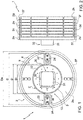
- number 1 indicates a wheel for vehicles, as a whole, manufactured by means of a plurality of disks 2 substantially equal to one another, arranged side by side.
- wheel 1 is manufactured by means of eight disks 2, including an pair of outer disks 2a and 2h and six inner disks respectively referred to by 2b, 2c, 2d, 2e, 2f and 2g; it is also evident that wheel 1 can be manufactured by means of any number of disks 2.
- the number of disks 2 is odd in number.
- the number of disks 2 is between three and eleven; preferably, the number of disks 2 is between five and nine.
- the disks 2 are preferably made of steel or aluminum alloy.
- each disk 2 comprises an inner collar 3 which is coaxial to a rotation axis X a and protrudes axially towards the outside of disk 2, and an outer collar 4 that is also coaxial to the rotation axis X a and that also protrudes axially towards the outside of disk 2.
- the two inner and outer collars 3 and 4 are connected together by means of a central portion 5 implemented by means of a wall that is substantially flat.
- Each disk 2 is also provided with an outer annular surface 6 and an inner annular surface 7 that define respectively an outer diameter D e and an inner diameter D i of disk 2.
- D also refers to the diameter of an inner annular surface 8 of the outer collar 4 (which is equal to the outer diameter D e from which the thickness of the outer collar 4 is subtracted) and D' refers to the diameter of an outer annular surface 3' of the inner collar 3 (which is equal to inner diameter D i to which the thickness of inner collar 3 is added).
- the inner diameters D i and the outer diameters D e of all of the disks 2 are equal therebetween. In alternative embodiments, the inner diameters D i and/or the outer diameters D e of the disks 2 differ (at least partly) from one another.
- the central portion 5 is divided into four sectors defined by as many apertures distributed evenly around the rotation axis X a .
- two larger oblong shaped (substantially rectangular) apertures 9 are provided that are diametrically opposing with respect to the rotation axis X a ; and two smaller apertures 10, which are also oblong shaped (substantially rectangular), extending from outer collar 4 and that are diametrically opposing with respect to the rotation axis X a .
- the larger apertures 9 extend from collar 4 and are delimited, at least from the front, by a portion 11 of the collar which protrudes transversely towards the outside of disk 2.
- the wheel 1 then comprises a hub 12 whereupon the disks 2 rotate.
- the hub 12 is implemented by means of a plurality of plates 13 arranged side by side.
- the hub 12 is implemented by means of a number of plates 13 that is equal to the number of disks 2 and thus a respective disk 2 is associated with each plate 13. Plates 13 are substantially equal therebetween and are coaxial to the rotation axis X a .
- Each plate 13 has an outer annular surface 14 and a through aperture bounded by an inner surface 15 featuring a section that is substantially square shaped and with rounded corners.
- the outer annular surface 14 defines an outer diameter d e that to the nearest tenth substantially approximates to the inner diameter D i of the disk 2.
- Each plate 13 carries housed bearings or bushings (of a known type and not described in detail) in order to allow for the rolling and/or creeping of the respective disk 2 disk on the outer annular surface 14.
- disks 2 are free to shift to one another in a vertical direction and are carried in rotation at the same angular velocity around respective rotation axes that are non-overlapping and parallel therebetween (marked with X a , X b , X c , X d , X e , X f , X g , X h in Figure 5 ).
- disks 2 are free to shift along a transverse direction (preferably perpendicular) to the rolling plane of wheel 1.
- wheel 1 comprises a coupling joint 16 intended to transmit the torque between the rotation axes of disks 2 that are parallel therebetween but not coincident.
- an Oldham coupling joint is employed.
- the Oldham coupling joint 16 is implemented by means of a plurality of rings 17 that are substantially equal therebetween. Each ring is interposed between two adjacent disks 2.
- the coupling joint 16 is implemented by means of seven rings 17 interposed between the eight disks 2.
- the acceleration or deceleration torque is transmitted to the innermost disk 2 (by means of an appropriate flange connection of a known type) and the joint 16 is intended to transmit this torque between the disks 2.
- each ring 17 is provided with an outer annular surface 18, wherein the diameter substantially approximates to the nearest tenth to the diameter D and with an inner annular surface 19, wherein the diameter substantially approximates to the nearest tenth to the diameter D' of the outer annular surface 3' of the inner collar 3.
- the width 1 of each ring 17 approximates to the nearest tenth to the width of the central portion 5 between the outer collar 4 and the inner collar 3.
- two adjacent disks 2a and 2b are arranged side by side in such a way that they are almost touching, respectively, the two outer collars 4 and the two inner collars 3; the ring 17 is entirely housed within the compartment defined between the two adjacent disks 2a, 2b, in particular, within the compartment defined between the inner collars 3 and the outer collars 4 of the disks 2a, 2b arranged side by side.
- the maximum thickness of each ring 17 approximates to the nearest tenth to the width defined between the two disks 2a, 2b arranged side by side.
- each ring 17 is divided into four portions that are uniformly distributed around the rotation axis X a , two portions 20 thereof protrude towards the adjacent disk 2a, each of which is delimited by a pair of shoulders 21.
- the portions 20 are diametrically opposed with respect to the rotation axis X a .
- the protruding portions 20, carry, connected at an intermediate height, a coupling extension 22.
- the coupling extensions 22 are also diametrically opposed with respect to the rotation axis X a ; and comprise an arm 23 that connects to the ring 17 and a plate 24 intended to engage with a respective larger aperture 9 of the adjacent disk 2a.
- each plate 24 is provided with a front surface of a rectangular shape and of dimensions that approximate to the nearest tenth to the dimensions of the larger aperture 9.
- Each protruding portion 20 is intended to couple itself to the adjacent disk 2a by means of the respective coupling extensions 22 that are implemented such as to engage with the larger apertures 9 of said adjacent disk 2a.
- the larger apertures 9 have play with respect to the coupling extensions 22 in such a way as to move along a direction W between two extreme positions wherein each coupling extension 22 abuts against an inner surface of the respective larger aperture 9.
- each ring 17 In the rear surface 25 of each ring 17, in correspondence with the coupling extensions 22, there are in contrast two recesses 26 formed that are intended, in use, to house the larger apertures 9 of the adjacent disk 2b.
- the rear surface 25 also carries two connected coupling extensions 27.
- the coupling extensions 27 are diametrically opposed with respect to the rotation axis X a .
- the coupling extensions 22 and the coupling extensions 27 are uniformly distributed around the rotation axis X a .
- the coupling extensions 27 comprise an arm 28 that connects to the ring 17 and a plate 29 intended to arrange itself in correspondence to a respective smaller aperture 10 of the adjacent disk 2b.
- an actuator device 30 is housed within the plates 13.
- the actuator device 30 is preferably of the pneumatic type. According to a preferred alternative the actuator device 30 is implemented by means of a single pneumatic actuator.
- the actuator device 30 comprises a tubular body 31 defining within the interior thereof, for each piston 32, a respective channel that is engaged in a sliding manner (in other words, a plurality of channels is defined, each destined for a corresponding piston 32); each piston 32 is movable along the vertical direction Y within the channel with a reciprocating rectilinear motion between an upper end of travel position and a lower end of travel position, and vice versa, under the thrust of an actuating element which is suitable for moving the piston 32.
- the actuator device 30 comprises a number of pistons 32 which is equal to the number of disks 2 and therefore to the number of plates 13.
- the actuator device 30 furthermore comprises an upper end of travel member and a lower end of travel member (not illustrated) associated with each respective piston 32 in order to arrest the travel of the respective piston 32.
- each piston 32 comes out from the tubular body 31 through a larger aperture 33 in order to engage with an upper through cavity 34 formed within the plate 13 with which it cooperates; and, similarly, each piston 32 comes out of the tubular body 31 through a lower aperture 35 and engages a lower through cavity, which is opposite the upper through cavity 34, obtained in plate 13 with which it cooperates.
- the tubular body 31 has, in section, a form that is complementary to the shape of the surface bounded by the inner surface 15 and a dimension, measured along the vertical direction Y, that is less than the dimension of the through aperture bounded by the inner surface 15; in this way, the tubular body 31 can move along the vertical direction Y, within the through aperture bounded by the inner surface 15.
- the tubular body 31 has, in section, a substantially squared shape with rounded corners.
- the device 30 is furthermore made in such a way as to be able to control the individual pistons 32 (each of which acts upon a respective disk 2 and upon a respective plate 13 in order to shift them along the vertical direction Y) independently of each other.
- the actuator device 30 is connected to a control unit CU that is capable of independently driving the individual actuation elements which control the movement of the pistons 32 along the vertical direction Y.
- the control unit CU is configured in order to determine the ground footprint FP which allows to optimize the performance of the vehicle and, subsequently, to independently control the individual actuating elements in such a way as to implement the ground footprint FP that allows to optimize the performance of the vehicle.
- the ground footprint FP that allows to optimize the performance of the vehicle is in fact implemented by means of a set of footprint fp sections, each of which is defined by a respective disk 2.
- the number of footprint fp sections that define the ground footprint FP of the wheel 1 is equal to the number of disks 2.
- the ground footprint FP that allows to optimize the performance of the vehicle is determined as a function of several parameters.
- Those parameters that are taken into account by the control unit CU in order to determine the ground footprint FP that allows to optimize the performance of the vehicle comprise, amongst others:
- Figure 6 illustrates some different ground footprints that can be implemented by means of the wheel 1; wherein, for example, the ground footprint FP shown in Figure 6a is implemented in the case wherein the vehicle proceeds at a constant speed on the highway, the ground footprint FP shown in Figure 6e is implemented in the case of sudden braking while the ground footprints FP illustrated in the figures from 6b to 6d are implemented under intermediate conditions such as in the case of weak acceleration or steering.
- the ground footprint FP shown in Figure 6a is implemented in the case wherein the vehicle proceeds at a constant speed on the highway
- the ground footprint FP shown in Figure 6e is implemented in the case of sudden braking
- the ground footprints FP illustrated in the figures from 6b to 6d are implemented under intermediate conditions such as in the case of weak acceleration or steering.
- control unit CU is configured in such a way as to control the individual actuating elements in order to obtain the corresponding footprint fp sections.
- control unit CU is configured in order to control the individual actuating elements in such a way that they provide pressure to the respective piston 32 in order to allow the latter to exert a force that is capable of moving the corresponding disk 2 and the corresponding plate 13 along the vertical direction Y in order to obtain the corresponding footprint fp section.
- the disks 2 are shifted along the vertical direction Y with respect to one another in an independent manner and are brought into rotation at the same speed around the respective rotation axes X a , X b , X c , X d , X e , X f , X g , X h , which are not coincident and parallel therebetween.
- the pressure applied to the central disks 2d, 2e is the maximum compared to the pressure applied to the peripheral disks 2a, 2b, 2c, 2f, 2g, 2h; whilst in order to implement the ground footprint FP in figure 6e , the same pressure is applied to all of the disks 2a, 2b, 2c, 2d, 2e, 2f, 2g, 2h.
- the actuator device 30 is of the hydraulic type.
- the actuator device 30 is implemented by means of a plurality of actuators, preferably of the pneumatic type, each of which is associated with a respective disk 2 and a respective plate 13 for the shifting thereof along the vertical direction Y.
- each disk 2 is externally enveloped by an annular tread belt 37 (schematically illustrated in figure 1 ) that can consist of a ring full of rubber or else it can feature within it a pressure air chamber; i.e. according to the latter alternative the assembly formed by each disk 2 and the respective plate 13 is used as a rim to which a pneumatic tyre is attached (of a known type and not described in detail) comprising a toroidal casing, at the sides of which there are two annular tyre beads, and that supports an annular tread strip.
- a pneumatic tyre of a known type and not described in detail
- a skim is arranged that is impermeable to air, it constitutes an inner liner, and has the function of holding the air within the pneumatic tyre in order to retain over the time the inflation pressure of the pneumatic tyre itself.
- each disk 2 is externally enveloped by an annular tread belt 37, which may consist of a ring full of rubber; between each tread belt 37 and the relative disk 2 an intermediate elastic structure 38 is interposed which is intended to provide radial elasticity to the wheel 1.
- This type of elastic structure 38 replaces the structure of the conventional pneumatic tyre in all the functions thereof, with the sole exception of the tread belt 37.
- the elastic structure 38 is made from a plastic material; in particular, it has been verified that for the manufacture of the elastic structure 38 polymer materials are particularly suitable, of the fluoropolymers (PVDF) type, such as Teflon or polycarbonates (PC). According to a preferred alternative, the elastic structure 38 is provided with a honeycomb pattern.
- PVDF fluoropolymers
- PC polycarbonates
- the wheel 1 described so far allows to implement a variable ground footprint FP which is obtained by means of a number of footprint fp sections that is equal to the number of disks 2 that the wheel 1 is provided of; a ground footprint FP thus obtained is able to perfectly adapt itself to the different types of maneuver that the vehicle is engaged in or to the various stresses the wheel 1 is subjected to and, at the same time, to adapt itself to the different conditions of the road traveled by the vehicle that may occur; furthermore, the wheel 1 is also able to easily adapt itself to the presence of obstructions (such as potholes, unevenness, bumps, etc.).
- obstructions such as potholes, unevenness, bumps, etc.
- the wheel 1 described above is capable of changing its own configuration (consequently varying the ground footprint FP thereof) in such a way as to optimize, from time to time, its own performance according to the external conditions at which it operates. Therefore, the performance offered by the wheel 1 described above is never the result of a compromise (downwards), but always the best achievable result with the best optimization.
Landscapes
- Engineering & Computer Science (AREA)
- Mechanical Engineering (AREA)
- Tires In General (AREA)
Abstract
Description
- The present invention relates to a wheel for vehicles.
- As is known, a pneumatic tyre comprises a toroidal casing, which features two annular tyre beads and supports an annular tread strip. Between the casing and the tread, a tread belt is interposed, which comprises a number of tread plies. The casing supports a pair of lateral walls (or sidewalls) arranged between the tread and the tyre beads. Within the casing ply, a skim is arranged that is impermeable to air. It constitutes an inner liner and has the function of holding the air within the pneumatic tyre in order to retain over the time the inflation pressure of the pneumatic tyre itself.
- The tread strip comprises a rubber compound and features a pattern obtained on the outer surface in order to ensure good performance under all conditions of use. In particular, the composition of the rubber compound and the design of the tread pattern influence the behavior of the tyre both in the case of longitudinal stresses (when accelerating or braking) and in the case of transverse stresses (when following a curve); furthermore, the composition of the rubber compound and the design of the tread pattern influence the behavior of the tyre on the various types of roadbed (dry, wet, flooded, uneven, icy...).
- The characteristics of the tread strip are necessarily determined such as to represent an acceptable compromise between the various requirements, and it is therefore not possible to optimize the performance of the pneumatic tyre under the various ground conditions or the various stresses to which it is subjected; for example, in order to confer to the pneumatic tyre a behavior that is at least fair on wet surfaces it is necessary to create water drainage routes that inevitably penalize the behavior on dry surfaces.
-
CN105946449 discloses a wheel type mechanism of which the radius can be adjusted. The wheel type mechanism comprises a wheel formed by a plurality of wheel spokes, wherein the wheel comprises the wheel spokes, and further comprises a radius adjusting assembly and a motor driving assembly. - The object of the present invention is to provide a wheel for vehicles that is both free of the problems of the state of the art and that is, in particular, easy and cheap to manufacture.
- According to the present invention a wheel for vehicles to that set forth in the appended claims is provided.
- The present invention will now be described with reference to the attached drawings, illustrating a nonlimiting exemplary embodiment, wherein:
-
Figure 1 is a front view of a first embodiment of a wheel for vehicles manufactured according to the present invention; -
Figure 2 is a side view of the wheel for vehicles offigure 1 ; -
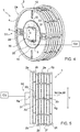
Figure 3 is a partially exploded and perspective view of the wheel for vehicles offigure 1 ; -
Figure 4 is a perspective view of the wheel for vehicles offigure 1 in a different operational configuration; -
Figure 5 is a side view of the wheel for vehicles offigure 1 in a different operational configuration; -
Figure 6 illustrates the different ground footprints left by the wheel for vehicles offigure 1 under various operating conditions; and -
Figure 7 is a front view of a second embodiment of the wheel for vehicles offigure 1 ; - In
figures 1 and 2 ,number 1 indicates a wheel for vehicles, as a whole, manufactured by means of a plurality ofdisks 2 substantially equal to one another, arranged side by side. In particular,wheel 1 is manufactured by means of eightdisks 2, including an pair ofouter disks wheel 1 can be manufactured by means of any number ofdisks 2. According to a preferred embodiment, the number ofdisks 2 is odd in number. According to a further embodiment, the number ofdisks 2 is between three and eleven; preferably, the number ofdisks 2 is between five and nine. - The
disks 2 are preferably made of steel or aluminum alloy. - As better illustrated in
figure 3 , eachdisk 2 comprises aninner collar 3 which is coaxial to a rotation axis Xa and protrudes axially towards the outside ofdisk 2, and anouter collar 4 that is also coaxial to the rotation axis Xa and that also protrudes axially towards the outside ofdisk 2. The two inner andouter collars central portion 5 implemented by means of a wall that is substantially flat. - Each
disk 2 is also provided with an outer annular surface 6 and an innerannular surface 7 that define respectively an outer diameter De and an inner diameter Di ofdisk 2. Infigures 1 and3 , D also refers to the diameter of an innerannular surface 8 of the outer collar 4 (which is equal to the outer diameter De from which the thickness of theouter collar 4 is subtracted) and D' refers to the diameter of an outer annular surface 3' of the inner collar 3 (which is equal to inner diameter Di to which the thickness ofinner collar 3 is added). - In the preferred illustrated embodiment, the inner diameters Di and the outer diameters De of all of the
disks 2 are equal therebetween. In alternative embodiments, the inner diameters Di and/or the outer diameters De of thedisks 2 differ (at least partly) from one another. - The
central portion 5 is divided into four sectors defined by as many apertures distributed evenly around the rotation axis Xa. In particular, two larger oblong shaped (substantially rectangular)apertures 9 are provided that are diametrically opposing with respect to the rotation axis Xa; and twosmaller apertures 10, which are also oblong shaped (substantially rectangular), extending fromouter collar 4 and that are diametrically opposing with respect to the rotation axis Xa. Preferably thelarger apertures 9 extend fromcollar 4 and are delimited, at least from the front, by aportion 11 of the collar which protrudes transversely towards the outside ofdisk 2. - The
wheel 1 then comprises ahub 12 whereupon thedisks 2 rotate. Thehub 12 is implemented by means of a plurality ofplates 13 arranged side by side. In particular, thehub 12 is implemented by means of a number ofplates 13 that is equal to the number ofdisks 2 and thus arespective disk 2 is associated with eachplate 13.Plates 13 are substantially equal therebetween and are coaxial to the rotation axis Xa. - Each
plate 13 has an outerannular surface 14 and a through aperture bounded by aninner surface 15 featuring a section that is substantially square shaped and with rounded corners. - The outer
annular surface 14 defines an outer diameter de that to the nearest tenth substantially approximates to the inner diameter Di of thedisk 2. - Each
plate 13 carries housed bearings or bushings (of a known type and not described in detail) in order to allow for the rolling and/or creeping of therespective disk 2 disk on the outerannular surface 14. - As better described in the discussion that follows and as illustrated in
figures 4 and 5 , inuse disks 2 are free to shift to one another in a vertical direction and are carried in rotation at the same angular velocity around respective rotation axes that are non-overlapping and parallel therebetween (marked with Xa, Xb, Xc, Xd, Xe, Xf, Xg, Xh inFigure 5 ). In particular,disks 2 are free to shift along a transverse direction (preferably perpendicular) to the rolling plane ofwheel 1. - In order to render the
disks 2 integral at an angle therebetween,wheel 1 comprises acoupling joint 16 intended to transmit the torque between the rotation axes ofdisks 2 that are parallel therebetween but not coincident. According to a preferred embodiment, an Oldham coupling joint is employed. The Oldhamcoupling joint 16 is implemented by means of a plurality ofrings 17 that are substantially equal therebetween. Each ring is interposed between twoadjacent disks 2. In particular, according to the illustrated embodiment, thecoupling joint 16 is implemented by means of sevenrings 17 interposed between the eightdisks 2. - The acceleration or deceleration torque is transmitted to the innermost disk 2 (by means of an appropriate flange connection of a known type) and the
joint 16 is intended to transmit this torque between thedisks 2. - As shown in
Figure 3 , eachring 17 is provided with an outerannular surface 18, wherein the diameter substantially approximates to the nearest tenth to the diameter D and with an innerannular surface 19, wherein the diameter substantially approximates to the nearest tenth to the diameter D' of the outer annular surface 3' of theinner collar 3. In other words, thewidth 1 of eachring 17 approximates to the nearest tenth to the width of thecentral portion 5 between theouter collar 4 and theinner collar 3. - With reference to that which is illustrated in
Figure 3 , twoadjacent disks outer collars 4 and the twoinner collars 3; thering 17 is entirely housed within the compartment defined between the twoadjacent disks inner collars 3 and theouter collars 4 of thedisks ring 17 approximates to the nearest tenth to the width defined between the twodisks - From the front, each
ring 17 is divided into four portions that are uniformly distributed around the rotation axis Xa, twoportions 20 thereof protrude towards theadjacent disk 2a, each of which is delimited by a pair ofshoulders 21. Theportions 20 are diametrically opposed with respect to the rotation axis Xa. - In particular, the protruding
portions 20, carry, connected at an intermediate height, acoupling extension 22. Thecoupling extensions 22 are also diametrically opposed with respect to the rotation axis Xa; and comprise anarm 23 that connects to thering 17 and aplate 24 intended to engage with a respectivelarger aperture 9 of theadjacent disk 2a. In particular, eachplate 24 is provided with a front surface of a rectangular shape and of dimensions that approximate to the nearest tenth to the dimensions of thelarger aperture 9. Each protrudingportion 20 is intended to couple itself to theadjacent disk 2a by means of therespective coupling extensions 22 that are implemented such as to engage with thelarger apertures 9 of saidadjacent disk 2a. Thelarger apertures 9 have play with respect to thecoupling extensions 22 in such a way as to move along a direction W between two extreme positions wherein eachcoupling extension 22 abuts against an inner surface of the respectivelarger aperture 9. - Within the
rear surface 25 of eachring 17, in correspondence with thecoupling extensions 22, there are in contrast tworecesses 26 formed that are intended, in use, to house thelarger apertures 9 of theadjacent disk 2b. - The
rear surface 25 also carries two connected coupling extensions 27. In particular, the coupling extensions 27 are diametrically opposed with respect to the rotation axis Xa. Thecoupling extensions 22 and the coupling extensions 27 are uniformly distributed around the rotation axis Xa. The coupling extensions 27 comprise anarm 28 that connects to thering 17 and aplate 29 intended to arrange itself in correspondence to a respectivesmaller aperture 10 of theadjacent disk 2b. - Finally, an
actuator device 30 is housed within theplates 13. Theactuator device 30 is preferably of the pneumatic type. According to a preferred alternative theactuator device 30 is implemented by means of a single pneumatic actuator. - Generally, the
actuator device 30 comprises atubular body 31 defining within the interior thereof, for eachpiston 32, a respective channel that is engaged in a sliding manner (in other words, a plurality of channels is defined, each destined for a corresponding piston 32); eachpiston 32 is movable along the vertical direction Y within the channel with a reciprocating rectilinear motion between an upper end of travel position and a lower end of travel position, and vice versa, under the thrust of an actuating element which is suitable for moving thepiston 32. Theactuator device 30 comprises a number ofpistons 32 which is equal to the number ofdisks 2 and therefore to the number ofplates 13. Theactuator device 30 furthermore comprises an upper end of travel member and a lower end of travel member (not illustrated) associated with eachrespective piston 32 in order to arrest the travel of therespective piston 32. - In the alternate rectilinear motion along the Y direction vertical thereof, each
piston 32 comes out from thetubular body 31 through alarger aperture 33 in order to engage with an upper throughcavity 34 formed within theplate 13 with which it cooperates; and, similarly, eachpiston 32 comes out of thetubular body 31 through alower aperture 35 and engages a lower through cavity, which is opposite the upper throughcavity 34, obtained inplate 13 with which it cooperates. - The
tubular body 31 has, in section, a form that is complementary to the shape of the surface bounded by theinner surface 15 and a dimension, measured along the vertical direction Y, that is less than the dimension of the through aperture bounded by theinner surface 15; in this way, thetubular body 31 can move along the vertical direction Y, within the through aperture bounded by theinner surface 15. In particular, thetubular body 31 has, in section, a substantially squared shape with rounded corners. - The
device 30 is furthermore made in such a way as to be able to control the individual pistons 32 (each of which acts upon arespective disk 2 and upon arespective plate 13 in order to shift them along the vertical direction Y) independently of each other. - In particular, the
actuator device 30 is connected to a control unit CU that is capable of independently driving the individual actuation elements which control the movement of thepistons 32 along the vertical direction Y. - The control unit CU is configured in order to determine the ground footprint FP which allows to optimize the performance of the vehicle and, subsequently, to independently control the individual actuating elements in such a way as to implement the ground footprint FP that allows to optimize the performance of the vehicle.
- The ground footprint FP that allows to optimize the performance of the vehicle is in fact implemented by means of a set of footprint fp sections, each of which is defined by a
respective disk 2. In other words, the number of footprint fp sections that define the ground footprint FP of thewheel 1 is equal to the number ofdisks 2. - In particular, the ground footprint FP that allows to optimize the performance of the vehicle is determined as a function of several parameters. Those parameters that are taken into account by the control unit CU in order to determine the ground footprint FP that allows to optimize the performance of the vehicle comprise, amongst others:
- the type of maneuver that the vehicle is engaged in and the type of stress to which the
wheel 1 is being subjected (accelerating, braking, steering, moving at a constant speed, etc.); - the conditions of the road being traveled by the vehicle (wet road, with ice and/or snow, etc.);
- the type of road being traveled by the vehicle (highway, city street, etc.);
- the performance of the
wheel 1 in terms of noise and comfort, etc.; and - the presence of any obstacles (potholes, unevenness, bumps, etc.).
-
Figure 6 illustrates some different ground footprints that can be implemented by means of thewheel 1; wherein, for example, the ground footprint FP shown inFigure 6a is implemented in the case wherein the vehicle proceeds at a constant speed on the highway, the ground footprint FP shown inFigure 6e is implemented in the case of sudden braking while the ground footprints FP illustrated in the figures from 6b to 6d are implemented under intermediate conditions such as in the case of weak acceleration or steering. - Depending upon the different ground footprint FP to be implemented, the control unit CU is configured in such a way as to control the individual actuating elements in order to obtain the corresponding footprint fp sections. In other words, the control unit CU is configured in order to control the individual actuating elements in such a way that they provide pressure to the
respective piston 32 in order to allow the latter to exert a force that is capable of moving thecorresponding disk 2 and thecorresponding plate 13 along the vertical direction Y in order to obtain the corresponding footprint fp section. - In order to implement the individual footprint fp sections, the
disks 2 are shifted along the vertical direction Y with respect to one another in an independent manner and are brought into rotation at the same speed around the respective rotation axes Xa, Xb, Xc, Xd, Xe, Xf, Xg, Xh, which are not coincident and parallel therebetween. - It seems clear that, for example, in order to implement the ground footprint FP in
figure 6b , the pressure applied to thecentral disks peripheral disks figure 6e , the same pressure is applied to all of thedisks - According to a possible alternative, the
actuator device 30 is of the hydraulic type. - According to a possible alternative, the
actuator device 30 is implemented by means of a plurality of actuators, preferably of the pneumatic type, each of which is associated with arespective disk 2 and arespective plate 13 for the shifting thereof along the vertical direction Y. - According to a possible alternative, each
disk 2 is externally enveloped by an annular tread belt 37 (schematically illustrated infigure 1 ) that can consist of a ring full of rubber or else it can feature within it a pressure air chamber; i.e. according to the latter alternative the assembly formed by eachdisk 2 and therespective plate 13 is used as a rim to which a pneumatic tyre is attached (of a known type and not described in detail) comprising a toroidal casing, at the sides of which there are two annular tyre beads, and that supports an annular tread strip. Within the casing ply, over the entire available surface, a skim is arranged that is impermeable to air, it constitutes an inner liner, and has the function of holding the air within the pneumatic tyre in order to retain over the time the inflation pressure of the pneumatic tyre itself. - According to a further alternative illustrated in
figure 7 , eachdisk 2 is externally enveloped by anannular tread belt 37, which may consist of a ring full of rubber; between eachtread belt 37 and therelative disk 2 an intermediateelastic structure 38 is interposed which is intended to provide radial elasticity to thewheel 1. This type ofelastic structure 38 replaces the structure of the conventional pneumatic tyre in all the functions thereof, with the sole exception of thetread belt 37. - The
elastic structure 38 is made from a plastic material; in particular, it has been verified that for the manufacture of theelastic structure 38 polymer materials are particularly suitable, of the fluoropolymers (PVDF) type, such as Teflon or polycarbonates (PC). According to a preferred alternative, theelastic structure 38 is provided with a honeycomb pattern. - The
wheel 1 described so far allows to implement a variable ground footprint FP which is obtained by means of a number of footprint fp sections that is equal to the number ofdisks 2 that thewheel 1 is provided of; a ground footprint FP thus obtained is able to perfectly adapt itself to the different types of maneuver that the vehicle is engaged in or to the various stresses thewheel 1 is subjected to and, at the same time, to adapt itself to the different conditions of the road traveled by the vehicle that may occur; furthermore, thewheel 1 is also able to easily adapt itself to the presence of obstructions (such as potholes, unevenness, bumps, etc.). - In other words, the
wheel 1 described above is capable of changing its own configuration (consequently varying the ground footprint FP thereof) in such a way as to optimize, from time to time, its own performance according to the external conditions at which it operates. Therefore, the performance offered by thewheel 1 described above is never the result of a compromise (downwards), but always the best achievable result with the best optimization.
Claims (15)
- Wheel (1) for vehicles comprising a plurality of disks (2) substantially equal to each other, arranged side by side and revolving at the same angular velocity around respective rotation axes (Xa, Xb, Xc, Xd, Xe, Xf, Xg, Xh), parallel to each other;
the wheel (1) is characterized in that it comprises:a coupling (16) which is capable of rendering the disks (2) integral at an angle therebetween, is intended to transmit the torque between the disks (2), and is capable of allowing for mutual sliding between the disks (2) along a vertical direction (Y), transverse to the rolling plane of the wheel (1); andat least one actuator device (30) that is capable of shifting each disk (2) along the vertical direction (Y) independently of the other disks (2), and in such way as to arrange the individual disks (2) with the respective rotation axes (X) parallel to each other and non-coincident. - Wheel according to claim 1, wherein:a hub (12) is provided onto which the disks (2) rotate, which is implemented by means of a plurality of plates (13) arranged side by side;each plate (13) is associated with a respective disk (2); andthe actuator device (30) is capable of shifting the assembly formed by each disk (2) and by the corresponding plate (13) along the vertical direction (Y).
- Wheel according to claim 2, wherein each plate (13) carries housed on an annular outer surface (14) bearings or bushings in order to allow for the rolling and/or the creeping of the respective disk (2).
- Wheel according to any one of the preceding claims, wherein:a control unit (CU) is provided which is configured to determine a ground footprint (FP) to be implemented by means of a set of footprint (fp) sections;each footprint (fp) section is implemented by means of a disk (2); andthe actuator device (30) is capable of shifting each disk (2) along the vertical direction (Y) as a function of the corresponding footprint section (fp).
- Wheel according to claim 4, wherein the ground footprint (FP) is a function of several parameters such as the type of maneuver the vehicle is engaged in, the type of stress the wheel (1) is subjected to, the conditions of the road traveled by the vehicle, the type of the road being traveled by the vehicle, the presence of any obstacles such as potholes, unevenness, bumps.
- Wheel according to any one of the preceding claims, wherein:the actuator device (30) comprises a tubular body (31) defining within the interior thereof at least one channel that is engaged in a sliding manner by a respective piston (32); andeach piston (32) is movable along the vertical direction (Y) within the channel with a reciprocating rectilinear motion between an upper end of travel position and a lower end of travel position, and vice versa, and cooperates with a respective disk (2) in order to shift it along the vertical direction (Y).
- Wheel according to one of the claims 1 to 6, and comprising a plurality of actuator devices (30), each of which cooperates with a respective disk (2) in order to shift it along the vertical direction (Y).
- Wheel according to claim 6 or 7, wherein the actuator device (30) is a fluid-dynamic actuator.
- Wheel according to any one of the preceding claims, wherein:each disk (2) is provided with an annular outer collar (3) which protrudes towards the outside of the disk (2) itself and with an inner collar (4) which also protrudes towards the outside of the disk (2); andthe two inner and outer collars (3, 4) are connected together by means of a central portion (5) implemented by means of a substantially flat wall.
- Wheel according to any one of the preceding claims, wherein the joint (16) is an Oldham joint and is implemented by means of a plurality of rings (17), each of which is interposed between two adjacent disks (2).
- Wheel according to claim 10, wherein each ring (17) is entirely housed within the compartment defined between the two adjacent disks (2), in particular within the compartment defined between the inner (3) and outer collars (4) of two disks (2) arranged one facing the other.
- Wheel according to claim 11, wherein:each disk (2) is provided with at least two through-apertures (9), diametrically opposed with respect to one another; andeach ring (17) carries connected at least two coupling extensions (22) that are diametrically opposed to one another and that are intended to engage with a respective through-aperture (9) of the adjacent disk (2).
- Wheel according to any one of the preceding claims, wherein each disk (2) is externally enveloped by a tread belt (37).
- Wheel according to claim 13, wherein between each tread belt (37) and the respective disk (2) an elastic structure (38) is interposed which is intended to provide radial elasticity to the wheel (1);
wherein the elastic structure (38) is made of a plastic material, preferably of a polymer material. - Wheel according to any one of claims from 1 to 12, wherein each disk (2) supports a pneumatic tyre comprising a toroidal casing that supports an annular tread strip.
Applications Claiming Priority (1)
| Application Number | Priority Date | Filing Date | Title |
|---|---|---|---|
| IT102017000121258A IT201700121258A1 (en) | 2017-10-25 | 2017-10-25 | WHEEL FOR VEHICLES |
Publications (2)
| Publication Number | Publication Date |
|---|---|
| EP3476622A1 true EP3476622A1 (en) | 2019-05-01 |
| EP3476622B1 EP3476622B1 (en) | 2019-11-20 |
Family
ID=61526943
Family Applications (1)
| Application Number | Title | Priority Date | Filing Date |
|---|---|---|---|
| EP18201621.2A Active EP3476622B1 (en) | 2017-10-25 | 2018-10-19 | Wheel for vehicles |
Country Status (2)
| Country | Link |
|---|---|
| EP (1) | EP3476622B1 (en) |
| IT (1) | IT201700121258A1 (en) |
Citations (4)
| Publication number | Priority date | Publication date | Assignee | Title |
|---|---|---|---|---|
| DE2753272A1 (en) * | 1977-11-30 | 1979-05-31 | Metzeler Kautschuk | Roller applying continuous profiles on tyre carcasses - where pressure chamber applies uniform pressure to system of offset rings |
| DE29914838U1 (en) * | 1999-08-25 | 2001-01-04 | BOMAG GmbH & Co. oHG, 56154 Boppard | Soil compaction device |
| FR3002186A1 (en) * | 2013-02-19 | 2014-08-22 | Peugeot Citroen Automobiles Sa | EMERGENCY WHEEL HAVING REDUCED SIZE DURING ITS STORAGE IN A VEHICLE AND VEHICLE COMPRISING SUCH AN EMERGENCY WHEEL |
| CN105946449A (en) * | 2016-04-29 | 2016-09-21 | 桂林电子科技大学 | Wheel type mechanism of which radius can be adjusted |
-
2017
- 2017-10-25 IT IT102017000121258A patent/IT201700121258A1/en unknown
-
2018
- 2018-10-19 EP EP18201621.2A patent/EP3476622B1/en active Active
Patent Citations (4)
| Publication number | Priority date | Publication date | Assignee | Title |
|---|---|---|---|---|
| DE2753272A1 (en) * | 1977-11-30 | 1979-05-31 | Metzeler Kautschuk | Roller applying continuous profiles on tyre carcasses - where pressure chamber applies uniform pressure to system of offset rings |
| DE29914838U1 (en) * | 1999-08-25 | 2001-01-04 | BOMAG GmbH & Co. oHG, 56154 Boppard | Soil compaction device |
| FR3002186A1 (en) * | 2013-02-19 | 2014-08-22 | Peugeot Citroen Automobiles Sa | EMERGENCY WHEEL HAVING REDUCED SIZE DURING ITS STORAGE IN A VEHICLE AND VEHICLE COMPRISING SUCH AN EMERGENCY WHEEL |
| CN105946449A (en) * | 2016-04-29 | 2016-09-21 | 桂林电子科技大学 | Wheel type mechanism of which radius can be adjusted |
Also Published As
| Publication number | Publication date |
|---|---|
| EP3476622B1 (en) | 2019-11-20 |
| IT201700121258A1 (en) | 2019-04-25 |
Similar Documents
| Publication | Publication Date | Title |
|---|---|---|
| EP3344476B1 (en) | Truck tire tread and truck tire | |
| CA2865520C (en) | Non-pneumatic tire | |
| EP3439899B1 (en) | Truck tire tread and truck tire | |
| JP4860721B2 (en) | Tires for vehicles | |
| JP6347774B2 (en) | Airless tire | |
| US4752079A (en) | Enhanced traction wheel assembly | |
| US6637834B2 (en) | Variable-diameter wheel apparatus for motor vehicles | |
| KR102429206B1 (en) | Non-pneumatic tire | |
| WO2003033276A1 (en) | Variable-diameter wheel-and-tire apparatus for motor vehicles | |
| EP3233533B1 (en) | Truck tire tread and truck tire | |
| KR20160040792A (en) | Variable tire | |
| EP3476622B1 (en) | Wheel for vehicles | |
| WO2012047149A1 (en) | An apparatus for preventing the skidding of a vehicle provided with wheels | |
| NO344265B1 (en) | Anti slip device for automobile wheels with wheel disc arranged at the inner side plane of the wheel | |
| JPH0424105A (en) | All weather pneumatic tire | |
| US3620278A (en) | Hybrid pneumatic-mechanical variable configuration wheel | |
| JP7727642B2 (en) | tire | |
| US4369825A (en) | Multiple wheel tire with reduced noise | |
| WO2007001246A1 (en) | Variable radial and/or lateral compliance wheel | |
| EP3941762B1 (en) | Tyre for vehicle wheels with notched gripping elements | |
| JP2007331668A (en) | Pneumatic tire, tire-rim wheel assembly, and vehicle | |
| JP2006335296A (en) | Tread structure for automobile tire, automobile tire using the tread and vehicle body structure for automobile | |
| JP2007331578A (en) | Pneumatic tire, tire-rim wheel assembly, and vehicle |
Legal Events
| Date | Code | Title | Description |
|---|---|---|---|
| PUAI | Public reference made under article 153(3) epc to a published international application that has entered the european phase |
Free format text: ORIGINAL CODE: 0009012 |
|
| STAA | Information on the status of an ep patent application or granted ep patent |
Free format text: STATUS: REQUEST FOR EXAMINATION WAS MADE |
|
| 17P | Request for examination filed |
Effective date: 20181019 |
|
| AK | Designated contracting states |
Kind code of ref document: A1 Designated state(s): AL AT BE BG CH CY CZ DE DK EE ES FI FR GB GR HR HU IE IS IT LI LT LU LV MC MK MT NL NO PL PT RO RS SE SI SK SM TR |
|
| AX | Request for extension of the european patent |
Extension state: BA ME |
|
| GRAP | Despatch of communication of intention to grant a patent |
Free format text: ORIGINAL CODE: EPIDOSNIGR1 |
|
| STAA | Information on the status of an ep patent application or granted ep patent |
Free format text: STATUS: GRANT OF PATENT IS INTENDED |
|
| INTG | Intention to grant announced |
Effective date: 20190704 |
|
| GRAS | Grant fee paid |
Free format text: ORIGINAL CODE: EPIDOSNIGR3 |
|
| GRAA | (expected) grant |
Free format text: ORIGINAL CODE: 0009210 |
|
| STAA | Information on the status of an ep patent application or granted ep patent |
Free format text: STATUS: THE PATENT HAS BEEN GRANTED |
|
| AK | Designated contracting states |
Kind code of ref document: B1 Designated state(s): AL AT BE BG CH CY CZ DE DK EE ES FI FR GB GR HR HU IE IS IT LI LT LU LV MC MK MT NL NO PL PT RO RS SE SI SK SM TR |
|
| REG | Reference to a national code |
Ref country code: GB Ref legal event code: FG4D |
|
| REG | Reference to a national code |
Ref country code: CH Ref legal event code: EP |
|
| REG | Reference to a national code |
Ref country code: IE Ref legal event code: FG4D |
|
| REG | Reference to a national code |
Ref country code: DE Ref legal event code: R096 Ref document number: 602018001284 Country of ref document: DE |
|
| REG | Reference to a national code |
Ref country code: AT Ref legal event code: REF Ref document number: 1203767 Country of ref document: AT Kind code of ref document: T Effective date: 20191215 |
|
| REG | Reference to a national code |
Ref country code: NL Ref legal event code: MP Effective date: 20191120 |
|
| REG | Reference to a national code |
Ref country code: LT Ref legal event code: MG4D |
|
| PG25 | Lapsed in a contracting state [announced via postgrant information from national office to epo] |
Ref country code: FI Free format text: LAPSE BECAUSE OF FAILURE TO SUBMIT A TRANSLATION OF THE DESCRIPTION OR TO PAY THE FEE WITHIN THE PRESCRIBED TIME-LIMIT Effective date: 20191120 Ref country code: GR Free format text: LAPSE BECAUSE OF FAILURE TO SUBMIT A TRANSLATION OF THE DESCRIPTION OR TO PAY THE FEE WITHIN THE PRESCRIBED TIME-LIMIT Effective date: 20200221 Ref country code: LT Free format text: LAPSE BECAUSE OF FAILURE TO SUBMIT A TRANSLATION OF THE DESCRIPTION OR TO PAY THE FEE WITHIN THE PRESCRIBED TIME-LIMIT Effective date: 20191120 Ref country code: NO Free format text: LAPSE BECAUSE OF FAILURE TO SUBMIT A TRANSLATION OF THE DESCRIPTION OR TO PAY THE FEE WITHIN THE PRESCRIBED TIME-LIMIT Effective date: 20200220 Ref country code: LV Free format text: LAPSE BECAUSE OF FAILURE TO SUBMIT A TRANSLATION OF THE DESCRIPTION OR TO PAY THE FEE WITHIN THE PRESCRIBED TIME-LIMIT Effective date: 20191120 Ref country code: NL Free format text: LAPSE BECAUSE OF FAILURE TO SUBMIT A TRANSLATION OF THE DESCRIPTION OR TO PAY THE FEE WITHIN THE PRESCRIBED TIME-LIMIT Effective date: 20191120 Ref country code: SE Free format text: LAPSE BECAUSE OF FAILURE TO SUBMIT A TRANSLATION OF THE DESCRIPTION OR TO PAY THE FEE WITHIN THE PRESCRIBED TIME-LIMIT Effective date: 20191120 Ref country code: BG Free format text: LAPSE BECAUSE OF FAILURE TO SUBMIT A TRANSLATION OF THE DESCRIPTION OR TO PAY THE FEE WITHIN THE PRESCRIBED TIME-LIMIT Effective date: 20200220 |
|
| PG25 | Lapsed in a contracting state [announced via postgrant information from national office to epo] |
Ref country code: HR Free format text: LAPSE BECAUSE OF FAILURE TO SUBMIT A TRANSLATION OF THE DESCRIPTION OR TO PAY THE FEE WITHIN THE PRESCRIBED TIME-LIMIT Effective date: 20191120 Ref country code: RS Free format text: LAPSE BECAUSE OF FAILURE TO SUBMIT A TRANSLATION OF THE DESCRIPTION OR TO PAY THE FEE WITHIN THE PRESCRIBED TIME-LIMIT Effective date: 20191120 Ref country code: IS Free format text: LAPSE BECAUSE OF FAILURE TO SUBMIT A TRANSLATION OF THE DESCRIPTION OR TO PAY THE FEE WITHIN THE PRESCRIBED TIME-LIMIT Effective date: 20200320 |
|
| PG25 | Lapsed in a contracting state [announced via postgrant information from national office to epo] |
Ref country code: AL Free format text: LAPSE BECAUSE OF FAILURE TO SUBMIT A TRANSLATION OF THE DESCRIPTION OR TO PAY THE FEE WITHIN THE PRESCRIBED TIME-LIMIT Effective date: 20191120 |
|
| PG25 | Lapsed in a contracting state [announced via postgrant information from national office to epo] |
Ref country code: DK Free format text: LAPSE BECAUSE OF FAILURE TO SUBMIT A TRANSLATION OF THE DESCRIPTION OR TO PAY THE FEE WITHIN THE PRESCRIBED TIME-LIMIT Effective date: 20191120 Ref country code: EE Free format text: LAPSE BECAUSE OF FAILURE TO SUBMIT A TRANSLATION OF THE DESCRIPTION OR TO PAY THE FEE WITHIN THE PRESCRIBED TIME-LIMIT Effective date: 20191120 Ref country code: PT Free format text: LAPSE BECAUSE OF FAILURE TO SUBMIT A TRANSLATION OF THE DESCRIPTION OR TO PAY THE FEE WITHIN THE PRESCRIBED TIME-LIMIT Effective date: 20200412 Ref country code: CZ Free format text: LAPSE BECAUSE OF FAILURE TO SUBMIT A TRANSLATION OF THE DESCRIPTION OR TO PAY THE FEE WITHIN THE PRESCRIBED TIME-LIMIT Effective date: 20191120 Ref country code: RO Free format text: LAPSE BECAUSE OF FAILURE TO SUBMIT A TRANSLATION OF THE DESCRIPTION OR TO PAY THE FEE WITHIN THE PRESCRIBED TIME-LIMIT Effective date: 20191120 Ref country code: ES Free format text: LAPSE BECAUSE OF FAILURE TO SUBMIT A TRANSLATION OF THE DESCRIPTION OR TO PAY THE FEE WITHIN THE PRESCRIBED TIME-LIMIT Effective date: 20191120 |
|
| REG | Reference to a national code |
Ref country code: AT Ref legal event code: MK05 Ref document number: 1203767 Country of ref document: AT Kind code of ref document: T Effective date: 20191120 |
|
| REG | Reference to a national code |
Ref country code: DE Ref legal event code: R097 Ref document number: 602018001284 Country of ref document: DE |
|
| PG25 | Lapsed in a contracting state [announced via postgrant information from national office to epo] |
Ref country code: SM Free format text: LAPSE BECAUSE OF FAILURE TO SUBMIT A TRANSLATION OF THE DESCRIPTION OR TO PAY THE FEE WITHIN THE PRESCRIBED TIME-LIMIT Effective date: 20191120 Ref country code: SK Free format text: LAPSE BECAUSE OF FAILURE TO SUBMIT A TRANSLATION OF THE DESCRIPTION OR TO PAY THE FEE WITHIN THE PRESCRIBED TIME-LIMIT Effective date: 20191120 |
|
| PLBE | No opposition filed within time limit |
Free format text: ORIGINAL CODE: 0009261 |
|
| STAA | Information on the status of an ep patent application or granted ep patent |
Free format text: STATUS: NO OPPOSITION FILED WITHIN TIME LIMIT |
|
| 26N | No opposition filed |
Effective date: 20200821 |
|
| PG25 | Lapsed in a contracting state [announced via postgrant information from national office to epo] |
Ref country code: PL Free format text: LAPSE BECAUSE OF FAILURE TO SUBMIT A TRANSLATION OF THE DESCRIPTION OR TO PAY THE FEE WITHIN THE PRESCRIBED TIME-LIMIT Effective date: 20191120 Ref country code: AT Free format text: LAPSE BECAUSE OF FAILURE TO SUBMIT A TRANSLATION OF THE DESCRIPTION OR TO PAY THE FEE WITHIN THE PRESCRIBED TIME-LIMIT Effective date: 20191120 |
|
| PG25 | Lapsed in a contracting state [announced via postgrant information from national office to epo] |
Ref country code: IT Free format text: LAPSE BECAUSE OF FAILURE TO SUBMIT A TRANSLATION OF THE DESCRIPTION OR TO PAY THE FEE WITHIN THE PRESCRIBED TIME-LIMIT Effective date: 20191120 |
|
| PG25 | Lapsed in a contracting state [announced via postgrant information from national office to epo] |
Ref country code: SI Free format text: LAPSE BECAUSE OF FAILURE TO SUBMIT A TRANSLATION OF THE DESCRIPTION OR TO PAY THE FEE WITHIN THE PRESCRIBED TIME-LIMIT Effective date: 20191120 |
|
| PG25 | Lapsed in a contracting state [announced via postgrant information from national office to epo] |
Ref country code: LU Free format text: LAPSE BECAUSE OF NON-PAYMENT OF DUE FEES Effective date: 20201019 Ref country code: MC Free format text: LAPSE BECAUSE OF FAILURE TO SUBMIT A TRANSLATION OF THE DESCRIPTION OR TO PAY THE FEE WITHIN THE PRESCRIBED TIME-LIMIT Effective date: 20191120 |
|
| REG | Reference to a national code |
Ref country code: BE Ref legal event code: MM Effective date: 20201031 |
|
| PG25 | Lapsed in a contracting state [announced via postgrant information from national office to epo] |
Ref country code: BE Free format text: LAPSE BECAUSE OF NON-PAYMENT OF DUE FEES Effective date: 20201031 |
|
| PG25 | Lapsed in a contracting state [announced via postgrant information from national office to epo] |
Ref country code: IE Free format text: LAPSE BECAUSE OF NON-PAYMENT OF DUE FEES Effective date: 20201019 |
|
| REG | Reference to a national code |
Ref country code: CH Ref legal event code: PL |
|
| PG25 | Lapsed in a contracting state [announced via postgrant information from national office to epo] |
Ref country code: TR Free format text: LAPSE BECAUSE OF FAILURE TO SUBMIT A TRANSLATION OF THE DESCRIPTION OR TO PAY THE FEE WITHIN THE PRESCRIBED TIME-LIMIT Effective date: 20191120 Ref country code: MT Free format text: LAPSE BECAUSE OF FAILURE TO SUBMIT A TRANSLATION OF THE DESCRIPTION OR TO PAY THE FEE WITHIN THE PRESCRIBED TIME-LIMIT Effective date: 20191120 Ref country code: CY Free format text: LAPSE BECAUSE OF FAILURE TO SUBMIT A TRANSLATION OF THE DESCRIPTION OR TO PAY THE FEE WITHIN THE PRESCRIBED TIME-LIMIT Effective date: 20191120 |
|
| PG25 | Lapsed in a contracting state [announced via postgrant information from national office to epo] |
Ref country code: MK Free format text: LAPSE BECAUSE OF FAILURE TO SUBMIT A TRANSLATION OF THE DESCRIPTION OR TO PAY THE FEE WITHIN THE PRESCRIBED TIME-LIMIT Effective date: 20191120 |
|
| PG25 | Lapsed in a contracting state [announced via postgrant information from national office to epo] |
Ref country code: LI Free format text: LAPSE BECAUSE OF NON-PAYMENT OF DUE FEES Effective date: 20211031 Ref country code: CH Free format text: LAPSE BECAUSE OF NON-PAYMENT OF DUE FEES Effective date: 20211031 |
|
| PGFP | Annual fee paid to national office [announced via postgrant information from national office to epo] |
Ref country code: FR Payment date: 20221031 Year of fee payment: 5 |
|
| PGFP | Annual fee paid to national office [announced via postgrant information from national office to epo] |
Ref country code: DE Payment date: 20221019 Year of fee payment: 5 |
|
| GBPC | Gb: european patent ceased through non-payment of renewal fee |
Effective date: 20221019 |
|
| PG25 | Lapsed in a contracting state [announced via postgrant information from national office to epo] |
Ref country code: GB Free format text: LAPSE BECAUSE OF NON-PAYMENT OF DUE FEES Effective date: 20221019 |
|
| REG | Reference to a national code |
Ref country code: DE Ref legal event code: R119 Ref document number: 602018001284 Country of ref document: DE |
|
| PG25 | Lapsed in a contracting state [announced via postgrant information from national office to epo] |
Ref country code: FR Free format text: LAPSE BECAUSE OF NON-PAYMENT OF DUE FEES Effective date: 20231031 Ref country code: DE Free format text: LAPSE BECAUSE OF NON-PAYMENT OF DUE FEES Effective date: 20240501 |