EP3476572A1 - Building method and building apparatus - Google Patents
Building method and building apparatus Download PDFInfo
- Publication number
- EP3476572A1 EP3476572A1 EP18195158.3A EP18195158A EP3476572A1 EP 3476572 A1 EP3476572 A1 EP 3476572A1 EP 18195158 A EP18195158 A EP 18195158A EP 3476572 A1 EP3476572 A1 EP 3476572A1
- Authority
- EP
- European Patent Office
- Prior art keywords
- building
- machining allowance
- thickness
- data
- color region
- Prior art date
- Legal status (The legal status is an assumption and is not a legal conclusion. Google has not performed a legal analysis and makes no representation as to the accuracy of the status listed.)
- Withdrawn
Links
Images

Classifications
-
- B—PERFORMING OPERATIONS; TRANSPORTING
- B29—WORKING OF PLASTICS; WORKING OF SUBSTANCES IN A PLASTIC STATE IN GENERAL
- B29C—SHAPING OR JOINING OF PLASTICS; SHAPING OF MATERIAL IN A PLASTIC STATE, NOT OTHERWISE PROVIDED FOR; AFTER-TREATMENT OF THE SHAPED PRODUCTS, e.g. REPAIRING
- B29C64/00—Additive manufacturing, i.e. manufacturing of three-dimensional [3D] objects by additive deposition, additive agglomeration or additive layering, e.g. by 3D printing, stereolithography or selective laser sintering
- B29C64/40—Structures for supporting 3D objects during manufacture and intended to be sacrificed after completion thereof
-
- B—PERFORMING OPERATIONS; TRANSPORTING
- B29—WORKING OF PLASTICS; WORKING OF SUBSTANCES IN A PLASTIC STATE IN GENERAL
- B29C—SHAPING OR JOINING OF PLASTICS; SHAPING OF MATERIAL IN A PLASTIC STATE, NOT OTHERWISE PROVIDED FOR; AFTER-TREATMENT OF THE SHAPED PRODUCTS, e.g. REPAIRING
- B29C64/00—Additive manufacturing, i.e. manufacturing of three-dimensional [3D] objects by additive deposition, additive agglomeration or additive layering, e.g. by 3D printing, stereolithography or selective laser sintering
- B29C64/30—Auxiliary operations or equipment
- B29C64/386—Data acquisition or data processing for additive manufacturing
- B29C64/393—Data acquisition or data processing for additive manufacturing for controlling or regulating additive manufacturing processes
-
- B—PERFORMING OPERATIONS; TRANSPORTING
- B29—WORKING OF PLASTICS; WORKING OF SUBSTANCES IN A PLASTIC STATE IN GENERAL
- B29C—SHAPING OR JOINING OF PLASTICS; SHAPING OF MATERIAL IN A PLASTIC STATE, NOT OTHERWISE PROVIDED FOR; AFTER-TREATMENT OF THE SHAPED PRODUCTS, e.g. REPAIRING
- B29C64/00—Additive manufacturing, i.e. manufacturing of three-dimensional [3D] objects by additive deposition, additive agglomeration or additive layering, e.g. by 3D printing, stereolithography or selective laser sintering
- B29C64/10—Processes of additive manufacturing
-
- B—PERFORMING OPERATIONS; TRANSPORTING
- B29—WORKING OF PLASTICS; WORKING OF SUBSTANCES IN A PLASTIC STATE IN GENERAL
- B29C—SHAPING OR JOINING OF PLASTICS; SHAPING OF MATERIAL IN A PLASTIC STATE, NOT OTHERWISE PROVIDED FOR; AFTER-TREATMENT OF THE SHAPED PRODUCTS, e.g. REPAIRING
- B29C64/00—Additive manufacturing, i.e. manufacturing of three-dimensional [3D] objects by additive deposition, additive agglomeration or additive layering, e.g. by 3D printing, stereolithography or selective laser sintering
- B29C64/10—Processes of additive manufacturing
- B29C64/106—Processes of additive manufacturing using only liquids or viscous materials, e.g. depositing a continuous bead of viscous material
- B29C64/112—Processes of additive manufacturing using only liquids or viscous materials, e.g. depositing a continuous bead of viscous material using individual droplets, e.g. from jetting heads
-
- B—PERFORMING OPERATIONS; TRANSPORTING
- B33—ADDITIVE MANUFACTURING TECHNOLOGY
- B33Y—ADDITIVE MANUFACTURING, i.e. MANUFACTURING OF THREE-DIMENSIONAL [3D] OBJECTS BY ADDITIVE DEPOSITION, ADDITIVE AGGLOMERATION OR ADDITIVE LAYERING, e.g. BY 3D PRINTING, STEREOLITHOGRAPHY OR SELECTIVE LASER SINTERING
- B33Y10/00—Processes of additive manufacturing
-
- B—PERFORMING OPERATIONS; TRANSPORTING
- B33—ADDITIVE MANUFACTURING TECHNOLOGY
- B33Y—ADDITIVE MANUFACTURING, i.e. MANUFACTURING OF THREE-DIMENSIONAL [3D] OBJECTS BY ADDITIVE DEPOSITION, ADDITIVE AGGLOMERATION OR ADDITIVE LAYERING, e.g. BY 3D PRINTING, STEREOLITHOGRAPHY OR SELECTIVE LASER SINTERING
- B33Y30/00—Apparatus for additive manufacturing; Details thereof or accessories therefor
-
- B—PERFORMING OPERATIONS; TRANSPORTING
- B33—ADDITIVE MANUFACTURING TECHNOLOGY
- B33Y—ADDITIVE MANUFACTURING, i.e. MANUFACTURING OF THREE-DIMENSIONAL [3D] OBJECTS BY ADDITIVE DEPOSITION, ADDITIVE AGGLOMERATION OR ADDITIVE LAYERING, e.g. BY 3D PRINTING, STEREOLITHOGRAPHY OR SELECTIVE LASER SINTERING
- B33Y50/00—Data acquisition or data processing for additive manufacturing
- B33Y50/02—Data acquisition or data processing for additive manufacturing for controlling or regulating additive manufacturing processes
Definitions
- the present invention relates to a building method and a building apparatus.
- a building apparatus that builds an object using an ink-jet head.
- the object is built by stacking a plurality of layers of ink formed by the ink-jet head.
- an object colored in various colors can be built by using ink for coloring as a building material.
- the object can be variously decorated by drawing a design such as various characters and patterns on a surface of the object (Patent Literature 1).
- Patent Literature 1 Japanese Unexamined Patent Publication No. 2015-147326
- the ink for coloring is not used for the entire object, but for generating a color region near the surface of the object.
- the color region is preferably thin to increase resolution of a color layer of the surface.
- the color region is preferably thick to widen a color expression range of the color layer of the surface.
- the present invention provides a method and an apparatus for building an object in which a deposition streak is caused to be inconspicuous.
- a building method is a method for building an object and includes: receiving data on thickness of a surface color region of the object from a user; generating building data including the surface color region having the thickness; and generating the object by depositing a building material based on the building data.
- the method for building an object may be a method for making an object by additive manufacturing, for example.
- color quality of the object surface can be controlled.
- a clear color can be reproduced with high-resolution.
- the surface color region is thickened, stable and wide color reproducibility having small variation in lots can be achieved.
- the surface color region encompasses the clear region.
- the building method according to the present invention is the method for building the object and includes: receiving data on thickness of a machining allowance of the object from a user; generating building data including the machining allowance having the thickness; generating the object by depositing a building material based on the building data; and polishing a surface of the object.
- the object including a machining allowance is generated, so that a desired object having an inconspicuous deposition streak can be obtained by performing finish processing of polishing the machining allowance.
- the user can set the thickness of the machining allowance, so that the machining allowance having an appropriate thickness can be made as appropriate to the object.
- building data may be generated, the generated building data including a machining allowance made of a same building material as the building material of the surface color region of the object.
- color density of the surface color region and the machining allowance may be determined in accordance with the thickness of the machining allowance.
- color density of the surface color region can be lowered than intended color density depending on the thickness of the machining allowance, and surface colors can be prevented from being largely different from each other due to a slight difference in a machining amount.
- an amount of color ink constituting the surface color region may be reduced, and clear ink is mixed therein corresponding to the reduced amount.
- building data may be generated, the generated building data including the machining allowance having a thickness equal to or smaller than a thickness of a clear ink layer.
- the machining allowance is transparent and inconspicuous.
- the building apparatus includes: an input unit, configured to receive data on the thickness of the surface color region of the object from the user; a building data generation unit, configured to generate building data including the surface color region having the thickness; and a building processing unit, configured to generate the object by depositing a building material based on the building data.
- color quality of the object surface can be controlled. For example, when the surface color region is thinned, a clear color can be reproduced with high-resolution. Alternatively, when the surface color region is thickened, stable and wide color reproducibility having small variation in lots can be achieved. As a result, the user can select whether to give high priority to the resolution or to give high priority to the color expression range depending on a type and a size of the object.
- the input unit causes the thickness of the surface color region to be selected from a plurality of thicknesses.
- the building apparatus includes: an input unit, configured to receive data on the thickness of the machining allowance of the object from the user; a building data generation unit, configured to generate building data including the machining allowance having the thickness; and a building processing unit, configured to generate the object by depositing a building material based on the building data.
- the object including the machining allowance is generated, so that a desired object having an inconspicuous deposition streak can be obtained by performing finish processing of polishing the object.
- the user can set the thickness of the machining allowance, so that the machining allowance having an appropriate thickness can be made as appropriate to the object.
- the building data generation unit may generate building data including the machining allowance made of a same building material as the building material of the surface color region of the object.
- the building data generation unit may generate building data including the surface color region and the machining allowance having color density determined in accordance with the thickness of the machining allowance.
- color density of the surface color region can be lowered than intended color density depending on the thickness of the machining allowance, and the surface colors can be prevented from being largely different from each other due to a slight difference in a machining amount.
- an amount of color ink constituting the surface color region may be reduced, and clear ink is mixed therein corresponding to the reduced amount.
- the building data generation unit may generate building data including the machining allowance having a thickness equal to or smaller than a thickness of a clear ink layer.
- the machining allowance is transparent and inconspicuous.
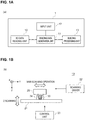
- FIGs. 1A and 1B are diagrams illustrating a configuration of a building apparatus 1 according to a first embodiment.
- the building apparatus 1 includes a 3D data reading unit 10 that reads 3D data on an object, a building data generation unit 11 that generates building data from the 3D data, an input unit 12 that receives an input of various settings and the like from a user, and a building processing unit 13 that deposits UV ink based on the building data to generate the object.
- the 3D data is data on a shape and a surface color of the object and is created based on data on external appearance and the like obtained by photographing the object to be manufactured.
- the 3D data is, for example, handled as a file in a format such as "VRML", "OBJ", and "PLY.”
- the building data generation unit 11 has a function of generating data that defines a material, a color, and the like constituting the object based on the 3D data, and defines which ink is applied to which position in each layer to be deposited to manufacture the object.
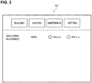
- FIG. 2 is a diagram illustrating an example of the input unit 12.
- the input unit 12 includes a building button for starting building, a history button for displaying a history of building in the past, a maintenance button for proceeding to a maintenance screen, and a setting button for proceeding to a setting screen of the building apparatus 1.
- the setting screen is displayed.
- a machining allowance can be set on this screen.
- the setting of the machining allowance is to set a machining amount in finish processing of polishing the object.
- the thickness of the machining allowance can be selected from “none”, “100 ⁇ m", and "200 ⁇ m” with radio boxes.
- a setting of a thickness of a color layer may be selected from “150 ⁇ m”, “250 ⁇ m”, and "350 ⁇ m".
- the input unit 12 receives a data input of the thickness of the machining allowance through the input screen illustrated in FIG. 2 , and the input unit 12 passes the input data on the machining allowance to the building data generation unit 11.
- the building data generation unit 11 generates the building data using the data on the thickness of the machining allowance input through the input unit 12.
- the building data generation unit 11 generates the building data on an object 30 including the machining allowance.
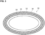
- FIG. 3 is a diagram illustrating the object 30 including a machining allowance 34.
- a mold material 31 is filled within the object 30, and a surface color region 32 is formed near the surface.
- a white region (white layer/reflective layer) 33 is formed on an inner side (lower side) of the surface color region 32, and when light entered through the surface of the surface color region 32 is reflected by the white region 33, a color can be reproduced based on a principle of a subtractive process.
- the surface color region 32 has a certain thickness in a normal direction of the surface, and the surface color region 32 can keep color quality constant.
- the machining allowance 34 continuous to the surface color region 32 on the outside of the surface color region 32.
- the machining allowance 34 has a certain thickness in the normal direction of the surface.
- the thickness of the machining allowance 34 is based on the data on the thickness input through the input unit 12.
- the same building material as that of the surface color region 32 is used for the machining allowance 34.
- An external shape of the object 30 formed by a surface of the outermost layer excluding the machining allowance 34 of the object 30 is constant independent of the thickness of the machining allowance 34 or the thickness of the surface color region 32. That is, variation in the thickness of each layer is directed toward the inside in the normal direction of the surface. Accordingly, the object 30 is built while maintaining the external shape of the read 3D data.
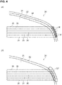
- FIG. 4A is a diagram illustrating respective layers 35 constituting the object 30 including the machining allowance 34. As illustrated in FIG. 4A , each layer 35 constituting the object 30 becomes longer than a case not including the machining allowance 34 corresponding to a portion 36 that covers the added machining allowance 34. As illustrated in FIG. 4A , by adding the machining allowance 34, the surface color region 32 is maintained when the surface is polished to be smoothed, so that the surface color of the object 30 can be maintained in a desired color.
- FIG. 4B is a diagram illustrating a configuration of the object 30 not including the machining allowance. As illustrated in FIG. 4B , when the machining allowance 34 is not added, part of the surface color region 32 may be shaved off as illustrated as a region 37, for example, in a polishing process of the surface, and coloring of the surface may be changed.
- the building processing unit 13 is a device that builds the stereoscopic object 30 by additive manufacturing by ejecting UV ink. As illustrated in FIG. 1B , the building processing unit 13 includes a head 20, a stage 21, a scanning driver 22, and a control unit 23.
- the head 20 is a portion that ejects droplets to be the material of the object 30, and the head 20 ejects the UV ink to be cured to form the layers constituting the object 30 in a stacking manner.
- the head 20 includes a plurality of ink-jet heads, a UV light source, a flattening roller, and the like.
- the head 20 can also form a support layer 24 around the object 30.
- the support layer 24 is, for example, a deposition structure that supports the object 30 by surrounding an outer circumference of the object 30 being built.
- the support layer 24 is formed as needed at the time of building the object 30, and the support layer 24 is removed after the building is completed.
- the stage 21 is a table-like member on which the object 30 being built is placed, and the stage 21 is arranged at a position opposed to the ink-jet head 30 in the head 20. At least an upper surface of the stage 21 is configured to be able to move upward and downward in the deposition direction, and when the stage 21 is driven by the scanning driver 22, at least the upper surface is moved in accordance with progress of the building of the object 30.
- the deposition direction is a direction (Z-direction in the drawing) orthogonal to a main scanning direction (Y-direction in the drawing) and a sub scanning direction (X-direction in the drawing) set in advance in the building processing unit 13.
- the scanning driver 22 is a driver that causes the head 20 to perform a scanning operation of moving relatively to the object 30.
- the scanning driver 22 causes the head 20 to perform a main scanning operation (Y-scanning), a sub scanning operation (X-scanning), and scanning in the deposition direction (Z-scanning) as the scanning operation.
- the main scanning operation is an operation of ejecting ink from the head 20 while moving the head 20 in the main scanning direction (Y-direction).
- the control unit 23 is, for example, a CPU of the building processing unit 13, and controls the building operation of the object 30 by controlling each part of the building processing unit 13.
- the CPU of the building processing unit 13 may also serve as a CPU of the building data generation unit 11.
- the control unit 23 controls each part of the building processing unit 13 based on the building data generated by the building data generation unit 11. Due to this, the building processing unit 13 stacks materials used for building in the deposition direction, and the building processing unit 13 builds the object 30 by additive manufacturing.
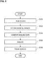
- FIG. 5 is a flowchart illustrating an operation of the building method according to the first embodiment.
- the building apparatus 1 reads 3D data on the object 30 (S10).
- the user sets the thickness of the machining allowance 34 through the input unit 12 (S12), and the building apparatus 1 generates the building data on the object 30 using the data on the set thickness of the machining allowance 34 (S14).
- the building data is data on each layer for generating the object 30 including the machining allowance 34.
- the building apparatus 1 performs building based on the generated building data (S16) and performs finish processing of polishing the generated object 30 (S18). Through the above operations, the object 30 is completed.
- the finish processing of polishing the object 30 may be performed by a person or by a machine.
- a basic configuration and operation of the building apparatus according to the second embodiment are the same as those in the first embodiment.
- the building data generation unit 11 adds the machining allowance to the object 30
- color density of the surface color region 32 of the object 30 is changed in accordance with the thickness of the machining allowance.
- FIG. 6 is a diagram illustrating an example of the building data including the machining allowance 34.
- the color density is lowered corresponding to the thickness of the machining allowance 34, and the machining allowance 34 made of the building material having the same color density as the lowered color density is added.
- density of the color ink is lowered, but design is made such that clear ink is filled in a portion where the color ink is not present.
- an amount of the color ink for generating the surface color region 32 and the machining allowance 34 is the same as an amount of the color ink for generating the surface color region in a case of not including the machining allowance.
- volume of the surface color region 32 is equal to volume of the machining allowance 34, the color density is caused to be 1/2. Accordingly, the surface color of the object 30 related to the building data becomes substantially the same as the surface color of the object 30 related to the 3D data.
- the thickness of the surface color region 32 is small and the color density thereof is high, slightly excessive polishing or an unpolished part in processing of polishing the surface may largely influence the surface color of the object 30.
- the present embodiment by lowering the color density of the surface color region 32 and the machining allowance 34 and by securing the thickness of the machining allowance 34 in a certain degree, sensitivity to a difference in the thickness of the surface color region 32 is lowered, and the processing of polishing the surface can be facilitated.
- a basic configuration and operation of the building apparatus according to the third embodiment are the same as those in the first embodiment.
- clear ink is used for the machining allowance to be added to the surface of the object 30.
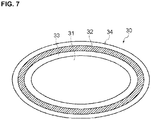
- FIG. 7 is a diagram illustrating the building data on the object 30 generated by the building apparatus according to the third embodiment. As illustrated in FIG. 7 , the machining allowance 34 made of the clear ink is added to the object 30.
- the object 30 including the machining allowance 34 is generated, so that the desired object 30 having an inconspicuous deposition streak can be obtained by performing finish processing of polishing the machining allowance 34.
- the user can set the thickness of the machining allowance 34, so that the machining allowance 34 having an appropriate thickness can be made as appropriate to the object 30.
- the color density is adjusted in accordance with the thicknesses of the surface color region 32 and the machining allowance 34, so that the surface color of the object 30 can be prevented from being darkened due to the machining allowance 34.
- the machining allowance is transparent and inconspicuous.
- the present invention is useful as a building apparatus that performs building by additive manufacturing, for example.
Landscapes
- Chemical & Material Sciences (AREA)
- Engineering & Computer Science (AREA)
- Materials Engineering (AREA)
- Manufacturing & Machinery (AREA)
- Physics & Mathematics (AREA)
- Mechanical Engineering (AREA)
- Optics & Photonics (AREA)
- Finishing Walls (AREA)
- Ink Jet (AREA)
Abstract
Description
- The present invention relates to a building method and a building apparatus.
- In the related art, there is known a building apparatus (3D printer) that builds an object using an ink-jet head. In such a building apparatus, for example, the object is built by stacking a plurality of layers of ink formed by the ink-jet head.
- In a case of building the object using the ink-jet head, an object colored in various colors can be built by using ink for coloring as a building material. The object can be variously decorated by drawing a design such as various characters and patterns on a surface of the object (Patent Literature 1).
- Patent Literature 1: Japanese Unexamined Patent Publication No.
2015-147326 - In the object generated by additive manufacturing, a large number of layers of ink are stacked. In a case in which a side surface inclines with respect to a deposition direction, layers constitute a level difference, so that a stack of the layers seems to be a line shape in some cases. Hereinafter, this is called a "deposition streak". To cause the deposition streak to be inconspicuous, after building the object, performed is finish processing of polishing the surface of the object with a polishing film, sandpaper, and the like.
- In building the colored object as described above, the ink for coloring is not used for the entire object, but for generating a color region near the surface of the object. There has been a problem such that, when the surface of the color object is polished, the color region of the object surface is thinned, and a surface color of the object is different from intended coloring. The color region is preferably thin to increase resolution of a color layer of the surface. By contrast, the color region is preferably thick to widen a color expression range of the color layer of the surface. Thus, there has been a demand for a function by which a user can select whether to give high priority to the resolution or to give high priority to the color expression range depending on a type and a size of the object.
- In view of the background described above, the present invention provides a method and an apparatus for building an object in which a deposition streak is caused to be inconspicuous.
- A building method according to the present invention is a method for building an object and includes: receiving data on thickness of a surface color region of the object from a user; generating building data including the surface color region having the thickness; and generating the object by depositing a building material based on the building data. The method for building an object may be a method for making an object by additive manufacturing, for example.
- With this configuration, color quality of the object surface can be controlled. For example, when the surface color region is thinned, a clear color can be reproduced with high-resolution. Alternatively, when the surface color region is thickened, stable and wide color reproducibility having small variation in lots can be achieved. In a case of having a clear region on the outside of the surface color region (that is, an outermost surface of the object), the surface color region encompasses the clear region.
- The building method according to the present invention is the method for building the object and includes: receiving data on thickness of a machining allowance of the object from a user; generating building data including the machining allowance having the thickness; generating the object by depositing a building material based on the building data; and polishing a surface of the object.
- With this configuration, the object including a machining allowance is generated, so that a desired object having an inconspicuous deposition streak can be obtained by performing finish processing of polishing the machining allowance. The user can set the thickness of the machining allowance, so that the machining allowance having an appropriate thickness can be made as appropriate to the object.
- In the building method according to the present invention, at the generating of the building data, building data may be generated, the generated building data including a machining allowance made of a same building material as the building material of the surface color region of the object.
- In this way, when the same building material is used for the machining allowance and the surface color region, there is no boundary between the surface color region and the machining allowance, and even when the machining allowance slightly remains at the polishing of the object, the remaining machining allowance becomes part of the surface color region of the object, whereby the remaining machining allowance is inconspicuous.
- In the building method according to the present invention, at the generating of the building data, color density of the surface color region and the machining allowance may be determined in accordance with the thickness of the machining allowance.
- With the configuration according to the present invention, color density of the surface color region can be lowered than intended color density depending on the thickness of the machining allowance, and surface colors can be prevented from being largely different from each other due to a slight difference in a machining amount. To lower the color density of the surface color region, for example, an amount of color ink constituting the surface color region may be reduced, and clear ink is mixed therein corresponding to the reduced amount.
- In the building method according to the present invention, at the generating of the building data, building data may be generated, the generated building data including the machining allowance having a thickness equal to or smaller than a thickness of a clear ink layer.
- In this way, by constituting the machining allowance with clear ink, even when the machining allowance remains in polish processing, the machining allowance is transparent and inconspicuous.
- The building apparatus according to the present invention includes: an input unit, configured to receive data on the thickness of the surface color region of the object from the user; a building data generation unit, configured to generate building data including the surface color region having the thickness; and a building processing unit, configured to generate the object by depositing a building material based on the building data.
- With this configuration, color quality of the object surface can be controlled. For example, when the surface color region is thinned, a clear color can be reproduced with high-resolution. Alternatively, when the surface color region is thickened, stable and wide color reproducibility having small variation in lots can be achieved. As a result, the user can select whether to give high priority to the resolution or to give high priority to the color expression range depending on a type and a size of the object.
- In the building apparatus according to the present invention, the input unit causes the thickness of the surface color region to be selected from a plurality of thicknesses.
- With this configuration, the user can easily select the thickness of the surface color region.
- The building apparatus according to the present invention includes: an input unit, configured to receive data on the thickness of the machining allowance of the object from the user; a building data generation unit, configured to generate building data including the machining allowance having the thickness; and a building processing unit, configured to generate the object by depositing a building material based on the building data.
- With this configuration, the object including the machining allowance is generated, so that a desired object having an inconspicuous deposition streak can be obtained by performing finish processing of polishing the object. The user can set the thickness of the machining allowance, so that the machining allowance having an appropriate thickness can be made as appropriate to the object.
- In the building apparatus according to the present invention, the building data generation unit may generate building data including the machining allowance made of a same building material as the building material of the surface color region of the object.
- In this way, when the same building material is used for the machining allowance and the surface color region, there is no boundary between the surface color region and the machining allowance, and even when the machining allowance slightly remains in polishing the object thereafter, the remaining machining allowance becomes part of the surface color region of the object, whereby the remaining machining allowance is inconspicuous.
- In the building apparatus according to the present invention, the building data generation unit may generate building data including the surface color region and the machining allowance having color density determined in accordance with the thickness of the machining allowance.
- With the configuration according to the present invention, color density of the surface color region can be lowered than intended color density depending on the thickness of the machining allowance, and the surface colors can be prevented from being largely different from each other due to a slight difference in a machining amount. To lower the color density of the surface color region, for example, an amount of color ink constituting the surface color region may be reduced, and clear ink is mixed therein corresponding to the reduced amount.
- In the building apparatus according to the present invention, the building data generation unit may generate building data including the machining allowance having a thickness equal to or smaller than a thickness of a clear ink layer.
- In this way, by constituting the machining allowance with clear ink, even when the machining allowance remains in polishing the object thereafter, the machining allowance is transparent and inconspicuous.
-
-
FIG. 1A is a diagram illustrating a configuration of a building apparatus according to an embodiment, andFIG. 1B is a diagram illustrating a configuration of a building processing unit. -
FIG. 2 is a diagram illustrating an example of an input unit. -
FIG. 3 is a diagram illustrating an object including a machining allowance. -
FIG. 4A is a diagram illustrating layers constituting the object including the machining allowance, andFIG. 4B is a diagram illustrating layers constituting the object not including the machining allowance. -
FIG. 5 is a flowchart illustrating an operation of a building apparatus according to a first embodiment. -
FIG. 6 is a diagram illustrating the object including the machining allowance. -
FIG. 7 is a diagram illustrating the object including the machining allowance. - The following describes a building apparatus and a building method according to embodiments of the present invention with reference to the drawings.
-
FIGs. 1A and 1B are diagrams illustrating a configuration of abuilding apparatus 1 according to a first embodiment. As illustrated inFIG. 1A , thebuilding apparatus 1 includes a 3Ddata reading unit 10 that reads 3D data on an object, a buildingdata generation unit 11 that generates building data from the 3D data, aninput unit 12 that receives an input of various settings and the like from a user, and abuilding processing unit 13 that deposits UV ink based on the building data to generate the object. - The 3D data is data on a shape and a surface color of the object and is created based on data on external appearance and the like obtained by photographing the object to be manufactured. The 3D data is, for example, handled as a file in a format such as "VRML", "OBJ", and "PLY." The building
data generation unit 11 has a function of generating data that defines a material, a color, and the like constituting the object based on the 3D data, and defines which ink is applied to which position in each layer to be deposited to manufacture the object. -
FIG. 2 is a diagram illustrating an example of theinput unit 12. Theinput unit 12 includes a building button for starting building, a history button for displaying a history of building in the past, a maintenance button for proceeding to a maintenance screen, and a setting button for proceeding to a setting screen of thebuilding apparatus 1. - In
FIG. 2 , the setting screen is displayed. A machining allowance can be set on this screen. The setting of the machining allowance is to set a machining amount in finish processing of polishing the object. In the example illustrated inFIG. 2 , the thickness of the machining allowance can be selected from "none", "100 µm", and "200 µm" with radio boxes. In place of the machining allowance, a setting of a thickness of a color layer may be selected from "150 µm", "250 µm", and "350 µm". - The
input unit 12 receives a data input of the thickness of the machining allowance through the input screen illustrated inFIG. 2 , and theinput unit 12 passes the input data on the machining allowance to the buildingdata generation unit 11. The buildingdata generation unit 11 generates the building data using the data on the thickness of the machining allowance input through theinput unit 12. - The building
data generation unit 11 generates the building data on anobject 30 including the machining allowance.FIG. 3 is a diagram illustrating theobject 30 including amachining allowance 34. Amold material 31 is filled within theobject 30, and asurface color region 32 is formed near the surface. A white region (white layer/reflective layer) 33 is formed on an inner side (lower side) of thesurface color region 32, and when light entered through the surface of thesurface color region 32 is reflected by thewhite region 33, a color can be reproduced based on a principle of a subtractive process. Thesurface color region 32 has a certain thickness in a normal direction of the surface, and thesurface color region 32 can keep color quality constant. - There is the
machining allowance 34 continuous to thesurface color region 32 on the outside of thesurface color region 32. Themachining allowance 34 has a certain thickness in the normal direction of the surface. The thickness of themachining allowance 34 is based on the data on the thickness input through theinput unit 12. The same building material as that of thesurface color region 32 is used for themachining allowance 34. An external shape of theobject 30 formed by a surface of the outermost layer excluding themachining allowance 34 of theobject 30 is constant independent of the thickness of themachining allowance 34 or the thickness of thesurface color region 32. That is, variation in the thickness of each layer is directed toward the inside in the normal direction of the surface. Accordingly, theobject 30 is built while maintaining the external shape of the read 3D data. -
FIG. 4A is a diagram illustratingrespective layers 35 constituting theobject 30 including themachining allowance 34. As illustrated inFIG. 4A , eachlayer 35 constituting theobject 30 becomes longer than a case not including themachining allowance 34 corresponding to aportion 36 that covers the addedmachining allowance 34. As illustrated inFIG. 4A , by adding themachining allowance 34, thesurface color region 32 is maintained when the surface is polished to be smoothed, so that the surface color of theobject 30 can be maintained in a desired color. -
FIG. 4B is a diagram illustrating a configuration of theobject 30 not including the machining allowance. As illustrated inFIG. 4B , when themachining allowance 34 is not added, part of thesurface color region 32 may be shaved off as illustrated as aregion 37, for example, in a polishing process of the surface, and coloring of the surface may be changed. - Subsequently, the following describes the
building processing unit 13 with reference toFIG. 1B . Thebuilding processing unit 13 is a device that builds thestereoscopic object 30 by additive manufacturing by ejecting UV ink. As illustrated inFIG. 1B , thebuilding processing unit 13 includes ahead 20, astage 21, ascanning driver 22, and acontrol unit 23. - The
head 20 is a portion that ejects droplets to be the material of theobject 30, and thehead 20 ejects the UV ink to be cured to form the layers constituting theobject 30 in a stacking manner. Thehead 20 includes a plurality of ink-jet heads, a UV light source, a flattening roller, and the like. - The
head 20 can also form asupport layer 24 around theobject 30. Thesupport layer 24 is, for example, a deposition structure that supports theobject 30 by surrounding an outer circumference of theobject 30 being built. Thesupport layer 24 is formed as needed at the time of building theobject 30, and thesupport layer 24 is removed after the building is completed. - The
stage 21 is a table-like member on which theobject 30 being built is placed, and thestage 21 is arranged at a position opposed to the ink-jet head 30 in thehead 20. At least an upper surface of thestage 21 is configured to be able to move upward and downward in the deposition direction, and when thestage 21 is driven by thescanning driver 22, at least the upper surface is moved in accordance with progress of the building of theobject 30. In this example, the deposition direction is a direction (Z-direction in the drawing) orthogonal to a main scanning direction (Y-direction in the drawing) and a sub scanning direction (X-direction in the drawing) set in advance in thebuilding processing unit 13. - The
scanning driver 22 is a driver that causes thehead 20 to perform a scanning operation of moving relatively to theobject 30. Thescanning driver 22 causes thehead 20 to perform a main scanning operation (Y-scanning), a sub scanning operation (X-scanning), and scanning in the deposition direction (Z-scanning) as the scanning operation. Herein, the main scanning operation is an operation of ejecting ink from thehead 20 while moving thehead 20 in the main scanning direction (Y-direction). - The
control unit 23 is, for example, a CPU of thebuilding processing unit 13, and controls the building operation of theobject 30 by controlling each part of thebuilding processing unit 13. The CPU of thebuilding processing unit 13 may also serve as a CPU of the buildingdata generation unit 11. Thecontrol unit 23 controls each part of thebuilding processing unit 13 based on the building data generated by the buildingdata generation unit 11. Due to this, thebuilding processing unit 13 stacks materials used for building in the deposition direction, and thebuilding processing unit 13 builds theobject 30 by additive manufacturing. -
FIG. 5 is a flowchart illustrating an operation of the building method according to the first embodiment. First, thebuilding apparatus 1 reads 3D data on the object 30 (S10). Subsequently, the user sets the thickness of themachining allowance 34 through the input unit 12 (S12), and thebuilding apparatus 1 generates the building data on theobject 30 using the data on the set thickness of the machining allowance 34 (S14). The building data is data on each layer for generating theobject 30 including themachining allowance 34. Thebuilding apparatus 1 performs building based on the generated building data (S16) and performs finish processing of polishing the generated object 30 (S18). Through the above operations, theobject 30 is completed. The finish processing of polishing theobject 30 may be performed by a person or by a machine. - Next, the following describes the building apparatus according to a second embodiment. A basic configuration and operation of the building apparatus according to the second embodiment are the same as those in the first embodiment. In the second embodiment, at the time when the building
data generation unit 11 adds the machining allowance to theobject 30, color density of thesurface color region 32 of theobject 30 is changed in accordance with the thickness of the machining allowance. -
FIG. 6 is a diagram illustrating an example of the building data including themachining allowance 34. In the second embodiment, the color density is lowered corresponding to the thickness of themachining allowance 34, and themachining allowance 34 made of the building material having the same color density as the lowered color density is added. To lower the color density, density of the color ink is lowered, but design is made such that clear ink is filled in a portion where the color ink is not present. - As an example of the color density of the building data, an amount of the color ink for generating the
surface color region 32 and themachining allowance 34 is the same as an amount of the color ink for generating the surface color region in a case of not including the machining allowance. For example, if volume of thesurface color region 32 is equal to volume of themachining allowance 34, the color density is caused to be 1/2. Accordingly, the surface color of theobject 30 related to the building data becomes substantially the same as the surface color of theobject 30 related to the 3D data. - In a case in which the thickness of the
surface color region 32 is small and the color density thereof is high, slightly excessive polishing or an unpolished part in processing of polishing the surface may largely influence the surface color of theobject 30. In the present embodiment, by lowering the color density of thesurface color region 32 and themachining allowance 34 and by securing the thickness of themachining allowance 34 in a certain degree, sensitivity to a difference in the thickness of thesurface color region 32 is lowered, and the processing of polishing the surface can be facilitated. - Next, the following describes a building apparatus according to a third embodiment. A basic configuration and operation of the building apparatus according to the third embodiment are the same as those in the first embodiment. In the third embodiment, clear ink is used for the machining allowance to be added to the surface of the
object 30. -
FIG. 7 is a diagram illustrating the building data on theobject 30 generated by the building apparatus according to the third embodiment. As illustrated inFIG. 7 , themachining allowance 34 made of the clear ink is added to theobject 30. - Effect of embodiments
- (1) The building method according to the present embodiment includes Step S12 for receiving the data on the thickness of the machining allowance of the
object 30 from the user, Step S14 for generating the building data including themachining allowance 34 having the set thickness, and Step S16 for generating theobject 30 by depositing the building material based on the building data. Thebuilding apparatus 1 according to the present embodiment includes theinput unit 12 that receives the data on the thickness of themachining allowance 34 of theobject 30 from the user, the buildingdata generation unit 11 that generates the building data including themachining allowance 34 having the set thickness, and thebuilding processing unit 13 that generates theobject 30 by depositing the building material based on the building data. - With this configuration, the
object 30 including themachining allowance 34 is generated, so that the desiredobject 30 having an inconspicuous deposition streak can be obtained by performing finish processing of polishing themachining allowance 34. The user can set the thickness of themachining allowance 34, so that themachining allowance 34 having an appropriate thickness can be made as appropriate to theobject 30. - (2) In the building method of the first embodiment, at Step S14 for generating the building data, generated is the building data including the
machining allowance 34 made of the same building material as that of thesurface color region 32 of theobject 30. In thebuilding apparatus 1 according to the first embodiment, the buildingdata generation unit 11 generates the building data including themachining allowance 34 made of the same building material as that of the surface color region of theobject 30. - In this way, when the same building material is used for the
machining allowance 34 and thesurface color region 32, there is no boundary between thesurface color region 32 and themachining allowance 34, and even when themachining allowance 34 slightly remains at Step S18 for polishing theobject 30, the remainingmachining allowance 34 becomes part of the surface color region of theobject 30, whereby the remaining machining allowance is inconspicuous. - (3) In the building method according to the second embodiment, at Step S14 for generating the building data, the color density of the
surface color region 32 and themachining allowance 34 is determined in accordance with the thickness of themachining allowance 34. In the building apparatus according to the second embodiment, the buildingdata generation unit 11 generates the building data including thesurface color region 32 and themachining allowance 34 having the color density determined in accordance with the thicknesses of thesurface color region 32 and themachining allowance 34. - With this configuration, the color density is adjusted in accordance with the thicknesses of the
surface color region 32 and themachining allowance 34, so that the surface color of theobject 30 can be prevented from being darkened due to themachining allowance 34. - (4) In the building method according to the third embodiment, at Step S14 for generating the building data, the building data including the machining allowance made of clear ink is generated. In the building apparatus according to the third embodiment, the building
data generation unit 11 generates the building data including the machining allowance made of clear ink. - In this way, by constituting the machining allowance with clear ink, even when the machining allowance remains in polishing the
object 30, the machining allowance is transparent and inconspicuous. - The present invention is useful as a building apparatus that performs building by additive manufacturing, for example.
Claims (11)
- A method for building an object (30), comprising:receiving data on thickness of a machining allowance of the object (30) from a user;generating building data including the machining allowance having the thickness;generating the object (30) by depositing a building material based on the building data; andpolishing a surface of the object (30).
- The building method according to claim 1, wherein, at the step of generating the building data, building data is generated that includes a machining allowance for the same building material as the building material of a surface color region of the object (30).
- The building method according to claim 2, wherein, at the step of generating the building data, a color density of the surface color region and the machining allowance is determined in accordance with the thickness of the machining allowance.
- The building method according to claim 1, at step of the generating the building data, building data is generated that includes a machining allowance having a thickness equal to or smaller than a thickness of a clear ink layer.
- A method for building an object (30), comprising:receiving data on thickness of a surface color region of the object (30) from a user;generating building data including the surface color region having the thickness; andgenerating the object (30) by depositing a building material based on the building data.
- A building apparatus (1) comprising:an input unit (12), configured to receive data on thickness of a machining allowance of an object (30) from a user;a building data generation unit (11), configured to generate building data including a machining allowance having the thickness; anda building processing unit (13), configured to generate the object (30) by depositing a building material based on the building data.
- The building apparatus (1) according to claim 6, wherein the building data generation unit (11) generates building data including a machining allowance made of the same building material as the building material of a surface color region of the object (30).
- The building apparatus (1) according to claim 7, wherein the building data generation unit (11) generates building data including the surface color region and the machining allowance having a color density determined in accordance with the thickness of the machining allowance.
- The building apparatus (1) according to claim 8, wherein the building data generation unit (11) generates building data including the machining allowance having a thickness equal to or smaller than a thickness of a clear ink layer.
- A building apparatus (1) comprising:an input unit (12), configured to receive data on thickness of a surface color region of an object (30) from a user;a building data generation unit (11), configured to generate building data including the surface color region having the thickness; anda building processing unit (13), configured to generate the object (30) by depositing a building material based on the building data.
- The building apparatus (1) according to claim 10, wherein the input unit (12) causes the thickness of the surface color region to be selected from a plurality of thicknesses.
Applications Claiming Priority (1)
| Application Number | Priority Date | Filing Date | Title |
|---|---|---|---|
| JP2017190877A JP7020843B2 (en) | 2017-09-29 | 2017-09-29 | Modeling method and modeling equipment |
Publications (1)
| Publication Number | Publication Date |
|---|---|
| EP3476572A1 true EP3476572A1 (en) | 2019-05-01 |
Family
ID=63642705
Family Applications (1)
| Application Number | Title | Priority Date | Filing Date |
|---|---|---|---|
| EP18195158.3A Withdrawn EP3476572A1 (en) | 2017-09-29 | 2018-09-18 | Building method and building apparatus |
Country Status (3)
| Country | Link |
|---|---|
| US (1) | US11607851B2 (en) |
| EP (1) | EP3476572A1 (en) |
| JP (1) | JP7020843B2 (en) |
Cited By (1)
| Publication number | Priority date | Publication date | Assignee | Title |
|---|---|---|---|---|
| CN112078129A (en) * | 2020-09-08 | 2020-12-15 | 鑫精合激光科技发展(北京)有限公司 | A part printing method and system, terminal device and computer storage medium |
Families Citing this family (1)
| Publication number | Priority date | Publication date | Assignee | Title |
|---|---|---|---|---|
| US20190126558A1 (en) * | 2017-11-02 | 2019-05-02 | Eos Gmbh Electro Optical Systems | Method and assembly for generating control data for the manufacture of a three-dimensional object by means of an additive manufacturing method |
Citations (5)
| Publication number | Priority date | Publication date | Assignee | Title |
|---|---|---|---|---|
| JP2003293012A (en) * | 2003-03-31 | 2003-10-15 | Matsushita Electric Works Ltd | Method for surface-finishing metal powder sintered parts |
| EP2431113A1 (en) * | 2009-05-15 | 2012-03-21 | Panasonic Corporation | Layered-modeling device and method using said device for manufacturing three-dimensional objects |
| FR3014355A1 (en) * | 2013-12-11 | 2015-06-12 | Essilor Int | METHOD FOR MANUFACTURING AN OPHTHALMIC LENS |
| JP2015147326A (en) | 2014-02-05 | 2015-08-20 | 株式会社ミマキエンジニアリング | Model and manufacturing method thereof |
| WO2016208213A1 (en) * | 2015-06-25 | 2016-12-29 | パナソニックIpマネジメント株式会社 | Method for manufacturing three-dimensionally shaped object |
Family Cites Families (5)
| Publication number | Priority date | Publication date | Assignee | Title |
|---|---|---|---|---|
| FR3006622B1 (en) * | 2013-06-07 | 2015-07-17 | Essilor Int | METHOD FOR MANUFACTURING AN OPHTHALMIC LENS |
| JP6413226B2 (en) * | 2013-11-12 | 2018-10-31 | セイコーエプソン株式会社 | Manufacturing method of three-dimensional structure |
| JP6497787B2 (en) * | 2014-03-11 | 2019-04-10 | スリーディー システムズ インコーポレーテッド | 3D printing ink |
| JP2016107406A (en) * | 2014-12-02 | 2016-06-20 | 株式会社リコー | Image processing device, image processing system, image processing program, and method of producing three-dimensional object |
| CN107209791A (en) * | 2015-01-30 | 2017-09-26 | 惠普发展公司有限责任合伙企业 | Generate the configuration data for producing three-dimensional body |
-
2017
- 2017-09-29 JP JP2017190877A patent/JP7020843B2/en active Active
-
2018
- 2018-09-06 US US16/122,906 patent/US11607851B2/en active Active
- 2018-09-18 EP EP18195158.3A patent/EP3476572A1/en not_active Withdrawn
Patent Citations (5)
| Publication number | Priority date | Publication date | Assignee | Title |
|---|---|---|---|---|
| JP2003293012A (en) * | 2003-03-31 | 2003-10-15 | Matsushita Electric Works Ltd | Method for surface-finishing metal powder sintered parts |
| EP2431113A1 (en) * | 2009-05-15 | 2012-03-21 | Panasonic Corporation | Layered-modeling device and method using said device for manufacturing three-dimensional objects |
| FR3014355A1 (en) * | 2013-12-11 | 2015-06-12 | Essilor Int | METHOD FOR MANUFACTURING AN OPHTHALMIC LENS |
| JP2015147326A (en) | 2014-02-05 | 2015-08-20 | 株式会社ミマキエンジニアリング | Model and manufacturing method thereof |
| WO2016208213A1 (en) * | 2015-06-25 | 2016-12-29 | パナソニックIpマネジメント株式会社 | Method for manufacturing three-dimensionally shaped object |
Cited By (2)
| Publication number | Priority date | Publication date | Assignee | Title |
|---|---|---|---|---|
| CN112078129A (en) * | 2020-09-08 | 2020-12-15 | 鑫精合激光科技发展(北京)有限公司 | A part printing method and system, terminal device and computer storage medium |
| CN112078129B (en) * | 2020-09-08 | 2022-05-17 | 鑫精合激光科技发展(北京)有限公司 | A part printing method and system, terminal device and computer storage medium |
Also Published As
| Publication number | Publication date |
|---|---|
| US20190099955A1 (en) | 2019-04-04 |
| JP7020843B2 (en) | 2022-02-16 |
| US11607851B2 (en) | 2023-03-21 |
| JP2019064091A (en) | 2019-04-25 |
Similar Documents
| Publication | Publication Date | Title |
|---|---|---|
| EP2148244B1 (en) | Improved Edge Smoothness with low resolution projected images for use in Solid Imaging | |
| US20160311162A1 (en) | Novel color 3d printer based on energy-curable color coating on transparent or translucent base material | |
| US11214009B2 (en) | Shaping system, shaping method, and shaped object | |
| US9302431B2 (en) | Rapid prototyping apparatus for producing three-dimensional ceramic object | |
| US10040275B2 (en) | Printing method for 3D printer | |
| US20200316849A1 (en) | Building apparatus, building method, and object | |
| US20240342980A1 (en) | 3d printing to obtain a predefined surface quality | |
| KR102003256B1 (en) | Variable extruding method of 3D printer, 3D model printing method and 3D model printing system | |
| JP6902365B2 (en) | 3D modeling method and 3D printer | |
| JP2000280354A (en) | Apparatus and method for there-dimensional shaping | |
| US11607851B2 (en) | Building method and building apparatus | |
| WO2017069245A1 (en) | Shaping system, method for controlling shaping operation, shaping control device, and program | |
| US20220031435A1 (en) | Method and system for additive manufacturing with a sacrificial structure for easy removal | |
| US10421235B2 (en) | Three-dimensional object, method for producing three-dimensional object, and three-dimensional object production apparatus | |
| CN118181831A (en) | Method for determining a printing parameter value of an inkjet printing device, data processing system, method and device for inkjet printing | |
| US20170355145A1 (en) | Printing system for printing an object with a pattern on a surface of the object | |
| CN111559076B (en) | Method for forming three-dimensional object | |
| JP2021045913A (en) | Printing equipment and printing method | |
| EP3279725A1 (en) | Printer and printing method for three dimensional objects | |
| JP6532378B2 (en) | Modeling system, control method of modeling operation, modeling control apparatus, and program | |
| JP2003145630A (en) | Three-dimensional shaping system and program | |
| JP2018196966A (en) | Three-dimensional modeling apparatus, modeling program, and three-dimensional model manufacturing method | |
| JP2008221835A (en) | Three-dimensional relief forming method and device | |
| CN112789158A (en) | Orientation and/or position of an object in additive manufacturing | |
| JP7750760B2 (en) | Method for adjusting a molding device, molding system, and method for manufacturing a confirmation molded object |
Legal Events
| Date | Code | Title | Description |
|---|---|---|---|
| PUAI | Public reference made under article 153(3) epc to a published international application that has entered the european phase |
Free format text: ORIGINAL CODE: 0009012 |
|
| STAA | Information on the status of an ep patent application or granted ep patent |
Free format text: STATUS: THE APPLICATION HAS BEEN PUBLISHED |
|
| AK | Designated contracting states |
Kind code of ref document: A1 Designated state(s): AL AT BE BG CH CY CZ DE DK EE ES FI FR GB GR HR HU IE IS IT LI LT LU LV MC MK MT NL NO PL PT RO RS SE SI SK SM TR |
|
| AX | Request for extension of the european patent |
Extension state: BA ME |
|
| STAA | Information on the status of an ep patent application or granted ep patent |
Free format text: STATUS: REQUEST FOR EXAMINATION WAS MADE |
|
| 17P | Request for examination filed |
Effective date: 20191104 |
|
| RBV | Designated contracting states (corrected) |
Designated state(s): AL AT BE BG CH CY CZ DE DK EE ES FI FR GB GR HR HU IE IS IT LI LT LU LV MC MK MT NL NO PL PT RO RS SE SI SK SM TR |
|
| STAA | Information on the status of an ep patent application or granted ep patent |
Free format text: STATUS: EXAMINATION IS IN PROGRESS |
|
| 17Q | First examination report despatched |
Effective date: 20210316 |
|
| STAA | Information on the status of an ep patent application or granted ep patent |
Free format text: STATUS: THE APPLICATION IS DEEMED TO BE WITHDRAWN |
|
| 18D | Application deemed to be withdrawn |
Effective date: 20220830 |