EP3476518A1 - Friction stir spot welding method and friction stir spot welding device - Google Patents
Friction stir spot welding method and friction stir spot welding device Download PDFInfo
- Publication number
- EP3476518A1 EP3476518A1 EP17820095.2A EP17820095A EP3476518A1 EP 3476518 A1 EP3476518 A1 EP 3476518A1 EP 17820095 A EP17820095 A EP 17820095A EP 3476518 A1 EP3476518 A1 EP 3476518A1
- Authority
- EP
- European Patent Office
- Prior art keywords
- spot welding
- welding portion
- tool
- cooling
- friction stir
- Prior art date
- Legal status (The legal status is an assumption and is not a legal conclusion. Google has not performed a legal analysis and makes no representation as to the accuracy of the status listed.)
- Granted
Links
Images





Classifications
-
- B—PERFORMING OPERATIONS; TRANSPORTING
- B23—MACHINE TOOLS; METAL-WORKING NOT OTHERWISE PROVIDED FOR
- B23K—SOLDERING OR UNSOLDERING; WELDING; CLADDING OR PLATING BY SOLDERING OR WELDING; CUTTING BY APPLYING HEAT LOCALLY, e.g. FLAME CUTTING; WORKING BY LASER BEAM
- B23K20/00—Non-electric welding by applying impact or other pressure, with or without the application of heat, e.g. cladding or plating
- B23K20/12—Non-electric welding by applying impact or other pressure, with or without the application of heat, e.g. cladding or plating the heat being generated by friction; Friction welding
-
- B—PERFORMING OPERATIONS; TRANSPORTING
- B23—MACHINE TOOLS; METAL-WORKING NOT OTHERWISE PROVIDED FOR
- B23K—SOLDERING OR UNSOLDERING; WELDING; CLADDING OR PLATING BY SOLDERING OR WELDING; CUTTING BY APPLYING HEAT LOCALLY, e.g. FLAME CUTTING; WORKING BY LASER BEAM
- B23K20/00—Non-electric welding by applying impact or other pressure, with or without the application of heat, e.g. cladding or plating
- B23K20/12—Non-electric welding by applying impact or other pressure, with or without the application of heat, e.g. cladding or plating the heat being generated by friction; Friction welding
- B23K20/122—Non-electric welding by applying impact or other pressure, with or without the application of heat, e.g. cladding or plating the heat being generated by friction; Friction welding using a non-consumable tool, e.g. friction stir welding
- B23K20/1275—Non-electric welding by applying impact or other pressure, with or without the application of heat, e.g. cladding or plating the heat being generated by friction; Friction welding using a non-consumable tool, e.g. friction stir welding involving metallurgical change
-
- B—PERFORMING OPERATIONS; TRANSPORTING
- B23—MACHINE TOOLS; METAL-WORKING NOT OTHERWISE PROVIDED FOR
- B23K—SOLDERING OR UNSOLDERING; WELDING; CLADDING OR PLATING BY SOLDERING OR WELDING; CUTTING BY APPLYING HEAT LOCALLY, e.g. FLAME CUTTING; WORKING BY LASER BEAM
- B23K20/00—Non-electric welding by applying impact or other pressure, with or without the application of heat, e.g. cladding or plating
- B23K20/12—Non-electric welding by applying impact or other pressure, with or without the application of heat, e.g. cladding or plating the heat being generated by friction; Friction welding
- B23K20/122—Non-electric welding by applying impact or other pressure, with or without the application of heat, e.g. cladding or plating the heat being generated by friction; Friction welding using a non-consumable tool, e.g. friction stir welding
- B23K20/1265—Non-butt welded joints, e.g. overlap-joints, T-joints or spot welds
-
- B—PERFORMING OPERATIONS; TRANSPORTING
- B23—MACHINE TOOLS; METAL-WORKING NOT OTHERWISE PROVIDED FOR
- B23K—SOLDERING OR UNSOLDERING; WELDING; CLADDING OR PLATING BY SOLDERING OR WELDING; CUTTING BY APPLYING HEAT LOCALLY, e.g. FLAME CUTTING; WORKING BY LASER BEAM
- B23K20/00—Non-electric welding by applying impact or other pressure, with or without the application of heat, e.g. cladding or plating
- B23K20/12—Non-electric welding by applying impact or other pressure, with or without the application of heat, e.g. cladding or plating the heat being generated by friction; Friction welding
- B23K20/122—Non-electric welding by applying impact or other pressure, with or without the application of heat, e.g. cladding or plating the heat being generated by friction; Friction welding using a non-consumable tool, e.g. friction stir welding
- B23K20/123—Controlling or monitoring the welding process
- B23K20/1235—Controlling or monitoring the welding process with temperature control during joining
-
- B—PERFORMING OPERATIONS; TRANSPORTING
- B23—MACHINE TOOLS; METAL-WORKING NOT OTHERWISE PROVIDED FOR
- B23K—SOLDERING OR UNSOLDERING; WELDING; CLADDING OR PLATING BY SOLDERING OR WELDING; CUTTING BY APPLYING HEAT LOCALLY, e.g. FLAME CUTTING; WORKING BY LASER BEAM
- B23K20/00—Non-electric welding by applying impact or other pressure, with or without the application of heat, e.g. cladding or plating
- B23K20/12—Non-electric welding by applying impact or other pressure, with or without the application of heat, e.g. cladding or plating the heat being generated by friction; Friction welding
- B23K20/122—Non-electric welding by applying impact or other pressure, with or without the application of heat, e.g. cladding or plating the heat being generated by friction; Friction welding using a non-consumable tool, e.g. friction stir welding
- B23K20/1245—Non-electric welding by applying impact or other pressure, with or without the application of heat, e.g. cladding or plating the heat being generated by friction; Friction welding using a non-consumable tool, e.g. friction stir welding characterised by the apparatus
-
- C—CHEMISTRY; METALLURGY
- C21—METALLURGY OF IRON
- C21D—MODIFYING THE PHYSICAL STRUCTURE OF FERROUS METALS; GENERAL DEVICES FOR HEAT TREATMENT OF FERROUS OR NON-FERROUS METALS OR ALLOYS; MAKING METAL MALLEABLE, e.g. BY DECARBURISATION OR TEMPERING
- C21D1/00—General methods or devices for heat treatment, e.g. annealing, hardening, quenching or tempering
- C21D1/18—Hardening; Quenching with or without subsequent tempering
-
- C—CHEMISTRY; METALLURGY
- C21—METALLURGY OF IRON
- C21D—MODIFYING THE PHYSICAL STRUCTURE OF FERROUS METALS; GENERAL DEVICES FOR HEAT TREATMENT OF FERROUS OR NON-FERROUS METALS OR ALLOYS; MAKING METAL MALLEABLE, e.g. BY DECARBURISATION OR TEMPERING
- C21D1/00—General methods or devices for heat treatment, e.g. annealing, hardening, quenching or tempering
- C21D1/34—Methods of heating
-
- C—CHEMISTRY; METALLURGY
- C21—METALLURGY OF IRON
- C21D—MODIFYING THE PHYSICAL STRUCTURE OF FERROUS METALS; GENERAL DEVICES FOR HEAT TREATMENT OF FERROUS OR NON-FERROUS METALS OR ALLOYS; MAKING METAL MALLEABLE, e.g. BY DECARBURISATION OR TEMPERING
- C21D9/00—Heat treatment, e.g. annealing, hardening, quenching or tempering, adapted for particular articles; Furnaces therefor
- C21D9/50—Heat treatment, e.g. annealing, hardening, quenching or tempering, adapted for particular articles; Furnaces therefor for welded joints
-
- B—PERFORMING OPERATIONS; TRANSPORTING
- B23—MACHINE TOOLS; METAL-WORKING NOT OTHERWISE PROVIDED FOR
- B23K—SOLDERING OR UNSOLDERING; WELDING; CLADDING OR PLATING BY SOLDERING OR WELDING; CUTTING BY APPLYING HEAT LOCALLY, e.g. FLAME CUTTING; WORKING BY LASER BEAM
- B23K20/00—Non-electric welding by applying impact or other pressure, with or without the application of heat, e.g. cladding or plating
- B23K20/12—Non-electric welding by applying impact or other pressure, with or without the application of heat, e.g. cladding or plating the heat being generated by friction; Friction welding
- B23K20/122—Non-electric welding by applying impact or other pressure, with or without the application of heat, e.g. cladding or plating the heat being generated by friction; Friction welding using a non-consumable tool, e.g. friction stir welding
- B23K20/1245—Non-electric welding by applying impact or other pressure, with or without the application of heat, e.g. cladding or plating the heat being generated by friction; Friction welding using a non-consumable tool, e.g. friction stir welding characterised by the apparatus
- B23K20/1255—Tools therefor, e.g. characterised by the shape of the probe
Definitions
- the present invention relates to a method and device for friction stir spot welding.
- a joint is manufactured by performing friction stir spot welding of a plurality of steel plates which are lapped to each other.
- the temperature of a spot welding portion of the steel plates is raised to a temperature at which austenitic transformation occurs by friction heat.
- the temperature of the spot welding portion is decreased. If martensitic transformation occurs while the temperature is decreased, the spot welding portion is cured (hardened) and becomes brittle. This results in reduced joint strength.
- Patent Literature 1 discloses that in a case where the temperature of the spot welding portion (portion to be welded) is increased up to a temperature that is equal to or higher than A3 transformation point, the rotational speed of the tool is reduced in a state in which the tool is inserted into a base metal, and the portion to be welded is gradually cooled. In a case where the temperature of the portion to be welded is decreased to A1 transformation point, the tool is pulled out (drawn out), and the portion to be welded is naturally cooled. By using this method, cooling is performed slowly to suppress formation of the martensite and suppress reduction of the joint strength.
- Patent Literature 1 Japanese-Laid Open Patent Application Publication No. 2011-115842
- the steel plates have a high hardenability
- long cooling time is required to prevent formation of the martensite.
- the base metal is medium-high carbon steel or alloy steel
- the above-described method has a drawback of productivity.
- To improve the productivity it is necessary to reduce the cooling time.
- the formation of the martensite cannot be suppressed. Therefore, it is difficult to keep high joint strength.
- An object of the present invention is to improve joint strength and productivity in a case where friction stir spot welding of steel plates is performed.
- a method of performing friction stir spot welding of a plurality of steel plates comprising the steps of: friction stirring a spot welding portion of the plurality of steel plates by pressing a tool against the spot welding portion while rotating the tool, to plasticize the spot welding portion by friction heat; cooling the spot welding portion to cause martensitic transformation to occur in the spot welding portion, after the step of friction stirring the spot welding portion; and tempering the spot welding portion by the friction heat by re-pressing the tool against the spot welding portion while rotating the tool, after the step of cooling the spot welding portion.
- spot welding portion is used to indicate a portion for which the friction stir spot welding is to be performed, a portion for which the friction stir spot welding is being performed, or a portion for which the friction stir spot welding has been performed, without distinguishing these portions from each other.
- the spot welding portion after the spot welding portion has been plasticized by the friction heat, the spot welding portion is quenched (hardened) by the cooling, and then tempered by use of the tool. This makes it possible to realize reduction of hardness and high toughness of the spot welding portion, and improve the joint strength.
- the tempering step is required, the tool used in the friction stirring step is used in the tempering step. Therefore, the steps from the friction stirring step to the tempering step can proceed smoothly in turn. As a result, productivity of the joint can be increased.
- the spot welding portion may be cooled at a cooling rate which is equal to or higher than an upper critical cooling rate of the plurality of steel plates.
- the martensite can be stably formed in the spot welding portion, and high joint strength can be kept. In addition, cooling time is reduced, and the productivity of the joint can be improved.
- a temperature of the spot welding portion may be decreased to a temperature which is equal to or lower than a martensitic transformation completion temperature of the plurality of steel plates.
- the martensite can be stably formed in the spot welding portion, and high joint strength can be kept.
- the step of cooling the spot welding portion may include pulling up the tool to form a space between the tool and the spot welding portion, and the tool may be pulled up so that a pull-up amount of the tool is less than a pin hole depth.
- a position deviation (position gap) between the tool and the pin hole can be suppressed. Therefore, it becomes possible to prevent a situation in which the tool undesirably interferes with the steel plate while the tool is re-pressed against the spot welding portion in the tempering step. As a result, break of the tool can be prevented.
- a temperature of the spot welding portion may be increased up to 550 to 650 degrees C and then decreased.
- the spot welding portion is tempered at a high temperature, it becomes possible to suitably realize reduction of hardness and high toughness of the spot welding portion.
- a rotational speed of the tool may be set to be higher than a rotational speed of the tool in the step of friction stirring the spot welding portion.
- the speed of re-heating in the tempering step is increased, and time required for the tempering step can be reduced.
- the plurality of steel plates may have a carbon content of 0.06% or more, or a tensile strength of 590MPa or higher.
- a device for performing friction stir spot welding of a plurality of steel plates comprising: a displacement driving unit which displaces a spot welding portion of the plurality of steel plates and a tool relative to each other; a rotation driving unit which rotates the tool; and a control unit, wherein the control unit performs a friction stirring step, in which the control unit causes the displacement driving unit and the rotation driving unit to operate to press the tool against the spot welding portion while rotating the tool, to plasticize the spot welding portion by friction heat, wherein the control unit performs a cooling step for cooling the spot welding portion, in which the control unit causes at least one of the displacement driving unit and the rotation driving unit to operate, to pull up the tool and/or reduce a rotational speed of the tool, and the control unit performs a tempering step for tempering the spot welding portion, in which the control unit causes the displacement driving unit and the rotation driving unit to operate to re-press the tool against the spot welding portion while rotating the tool.
- Fig. 1 is a view schematically showing a friction stir spot welding device 1 according to Embodiment 1.
- the friction stir spot welding device 1 is configured to rotate and displace a tool 10 with a substantially cylindrical shape, to perform friction stir spot welding of two steel plates 51, 52 lapped to each other.
- a plurality of spot welding portions 53 are set or formed in the two steel plates 51, 52.
- the two steel plates 51, 52 are welded (joined) to each other at the plurality of spot welding portions 53.
- the friction stir spot welding device 1 includes a base 11, a movable member 12, and a tool retaining member 13.
- the movable member 12 is mounted on the base 11 so that the movable member 12 is movable in the axis line direction of the tool retaining member 13.
- the tool retaining member 13 is rotatable around its axis line.
- the tool retaining member 13 is movable together with the movable member 12 in the axis line direction.
- the tool 10 is detachably retained at the tip end portion of the tool retaining member 13 and placed coaxially with the tool retaining member 13.
- tool axis A the axis line of the tool retaining member 13 and the axis line of the tool 10 retained by the tool retaining member 13
- tool axis direction The extension direction of the tool axis A
- the friction stir spot welding device 1 includes a frame 14 and a support base 15.
- the frame 14 is secured to the base 11.
- the frame 14 extends from the base 11 while being curved in a L-shape or a C-shape.
- the tip end portion of the frame 14 faces the tool 10 in the tool axis direction.
- the support base 15 is provided at the tip end portion of the frame 14, and supports the steel plates 51, 52 (in particular, spot welding portion 53).
- the friction stir spot welding device 1 includes a linear motion driving unit 16 and a rotation driving unit 17.
- the linear motion driving unit 16 linearly moves the movable member 12 in the tool axis direction. By this linear motion of the movable member 12, the tool 10 is displaced in the tool axis direction with respect to the two steel plates 51, 52 supported by the support base 15.
- the rotation driving unit 17 rotates the tool retaining member 13 and the tool 10 around the tool axis A.
- the linear motion driving unit 16 and the rotation driving unit 17 are, for example, electric (electrically powered) motors.
- the base 11 is detachably mounted on the tip end portion of an arm 19a of an articulated (multi-joint) robot 19.
- the arm 19a operates, the base 11 is displaced with respect to a base (not shown) of the articulated robot 19, and thus the tool 10 is displaced with respect to the steel plates 51, 52.
- the arm 19a of the articulated robot 19 and the linear motion driving unit 16 serve as a displacement driving unit 18 which displace the tool 10 and the spot welding portion 53 of the steel plates 51, 52, relative to each other.
- the friction stir spot welding device 1 includes a cooling device 20 which cools the spot welding portion 53.
- the cooling device 20 includes a nozzle 21 which injects a fluid.
- the nozzle 21 is connected to a fluid source 22 via a pipe 23.
- the pipe 23 is provided with a switching unit 24 which performs switching between injection and non-injection of the fluid from the nozzle 21.
- the fluid source 22 is a tank which stores the fluid in a pressure higher than an atmospheric pressure
- the switching unit 24 is an electromagnetic on/off valve. In this case, when the electromagnetic on/off valve as the switching unit 24 is opened, the fluid is injected from the nozzle 21, while when the electromagnetic on/off valve is closed, the injection of the fluid is stopped (ceased).
- the nozzle 21 is provided at the base 11. An injection opening of the nozzle 21 is directed toward the tip end portion of the tool retaining member 13.
- the fluid source 22 may be mounted on the base 11 or may be located to be distant from the base 11 outside the base 11.
- the friction stir spot welding device 1 includes a control unit 30 which controls the rotation driving unit 17, the displacement driving unit 18, and the cooling device 20 (in the present embodiment, in particular, the switching unit 24).
- the control unit 30 may be a single control unit with an integrated function, or a plurality of control units with distributed functions.
- the control unit 30 includes a processor, a volatile memory, a non-volatile memory, an I/O interface, or the like.
- the processor of the control unit 30 performs calculations (computations) by use of the volatile memory based on an operation program stored in the non-volatile memory, and the control unit 30 communicates with the rotation driving unit 17, the displacement driving unit 18 and the cooling device 20 via the I/O interface.
- an input device e.g., a computer, a teaching pendant or an operation board (control panel)
- the processor of the control unit 30 performs calculations (computations) by use of the volatile memory based on an operation program stored in the non-volatile memory, and the control unit 30 communicates with the rotation driving unit 17, the displacement driving unit 18 and the cooling device 20 via the I/O interface.
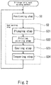
- Fig. 2 is a flowchart showing the friction stir spot welding method according to Embodiment 1.
- the steel plates 51, 52 are positioned with respect to the friction stir spot welding device 1 so that one spot welding portion 53 is supported on the support base 15 and faces the tool 10 in the tool axis direction (positioning step S1).
- the arm 19a of the articulated robot 19 may be operated to displace the base 11, the steel plates 51, 52 may be displaced with respect to the base 11 by a workpiece transfer device (not shown), or the displacement of the base 11 and the displacement of the steel plates 51, 52 may be combined.
- spot welding step S2 the friction stir spot welding is performed for one spot welding portion 53 supported on the support base 15 (spot welding step S2).
- spot welding step S2 performed once, a plunging step S21, a friction stirring step S22, a cooling step S23, and a tempering step S24 are performed in this order.
- the process returns to the positioning step S1.
- the steel plates 51, 52 are positioned with respect to the friction stir spot welding device 1 so that the spot welding portion 53 to be treated next is supported on the support base 15.
- the steel plates 51, 52 are welded (joined) to each other at the plurality of spot welding portions 53.
- the friction stir spot welding method ends when a condition (e.g., predetermined number of spot welding steps S2 are completed, or a maintenance is needed) is met, although this is not shown in detail.
- Fig. 3A is an enlarged view of Fig. 1 , showing a state in which the positioning step S1 is completed.
- the two steel plates 51, 52 are supported on the support base 15 in a state in which a plate thickness direction and a lapping direction conform to the tool axis direction.
- the steel plate 52 is placed on the support surface of the support base 15, and the steel plate 51 is lapped on the steel plate 52.
- the tool 10 includes a cylindrical tool body 10a and a pin 10b protruding from the center of the tool body 10a.
- the pin 10b has a diameter smaller than that of the tool body 10a.
- shoulder surface 10c a ring-shaped surface which is the end surface in the tool axis direction, of the tool body 10a, and surrounds the pin 10b.
- Fig. 3B is a view taken in the direction of arrow B of Fig. 3A , showing a state in which the steel plates 51, 52 are seen in the plate thickness direction (i.e., tool axis direction).
- the spot welding portion 53 shown at a lower side is the spot welding portion 53 which has gone through the spot welding step S2 (reference symbols 53a, 53b will be discussed later).
- the spot welding portion 53 shown at a middle side is the spot welding portion 53 which does not go through spot welding step S2 yet, after the positioning step S1 has been completed.
- the spot welding portion 53 shown at an upper side is the spot welding portion 53 which is a target for which the positioning step S1 and the spot welding step S2 are to be performed, after the spot welding step S2 for, for example, the spot welding portion 53 shown at the middle side has been completed.
- the tool 10 is moved in the tool axis direction while rotating the tool 10 around the tool axis A. In this way, the tool 10 is plunged into the steel plates 51, 52.
- the pin 10b While the rotating tool 10 is moved, initially, the pin 10b is pressed against the surface (upper surface in Figs. 4A and 4B ), of the steel plate 51. A portion of the steel plate 51 against which the pin 10b is pressed, is softened by friction heat. Since the portion of the steel plate 51 is softened, the pin 10b is further moved in the tool axis direction, from the surface of the steel plate 51. The pin 10b is plunged into the steel plate 51, penetrates the steel plate 51, and reaches the surface (upper surface in Figs. 4A and 4B ) of the steel plate 52. Likewise, a portion of the steel plate 52 is softened by the friction heat. The pin 10b is further moved in the tool axis direction from the surface of the steel plate 52, and is plunged into the steel plate 52.
- the tool 10 is moved until the shoulder surface 10c is pressed against the surface (upper surface in Figs. 4A and 4B ) of the steel plate 51.
- the pin 10b penetrates the steel plate 51 and is plunged into the steel plate 52. In the present embodiment, the pin 10b does not penetrate the steel plate 52.
- the tool 10 is pressed against (applies a pressing force to) the spot welding portion 53 while rotating the tool 10, to plasticize the spot welding portion 53 by the friction heat. Since the pin 10b has reached the steel plate 52, the steel plate 51 and the steel plate 52 are kneaded and mixed with each other at the spot welding portion 53 (see cross-hatched region in Fig. 4B ).
- the "pressing force” (pressure) applied by the tool 10 to the steel plates 51, 52 in the friction stirring step S22 is a force "N" in the tool axis direction (downward direction in the drawings) applied by the tool 10 to the steel plate 51, except otherwise noted.
- the cooling step S23 the tool 10 is pulled (drawn) up, and thus a space 54 is formed between the tool 10 and the spot welding portion 53 (tool pulling-up step S23a). Then, the fluid is poured (fed) into the space 54 to forcibly cool the spot welding portion 53 (liquid supply step S23b).
- the tool pulling-up step S23a the tool 10 is moved in the tool axis direction and retracted from the spot welding portion 53. At this time, the rotation of the tool 10 may be stopped or may be continued. Further, the tool 10 may be rotated in a direction opposite to the rotation during the plunging step.
- the cooling device 20 operates.
- the fluid is injected from the nozzle 21.
- the fluid may be a liquid or a gas.
- cooled air or an inactive (inert) gas such as nitrogen or argon can be suitably used.
- the inactive gas may also be cooled to have a temperature lower than that of ambient air.
- a pull-up amount X of the tool 10 is less than a pin-hole depth Y.
- a pin hole 53a is a plunge indentation of the pin 10b which is formed in the spot welding portion 53 when the pin 10b is pulled up.
- the pin hole 53a is a circular non-through hole.
- the pin-hole depth Y is a length in the plate thickness direction (tool axis direction) from the upper edge of the pin hole 53a to the bottom surface of the pin hole 53a.
- the upper edge of the pin hole 53a corresponds to a portion with which a corner portion formed by the outer peripheral surface of the pin 10b and the shoulder surface 10c made a contact.
- the tip end of the pin 10b stays at a location that is lower than the upper edge of the pin hole 53a.
- the shoulder surface 10c is apart from and above the steel plate 51.
- the pin 10b is apart from and above the bottom surface of the pin hole 53a, and a part of the pin 10b is located within the pin hole 53a.
- a gap is formed between the pin 10b and the upper edge of the pin hole 53a. The fluid injected from the nozzle 21 flows through this gap and reaches the inside of the pin hole 53a.
- the inner peripheral surface of the pin hole 53a and the inside of the pin hole 53a can be forcibly cooled by this fluid.
- the tool 10 is pressed against the spot welding portion 53 while rotating the tool 10, to perform tempering of the spot welding portion 53 by the friction heat.
- the tool 10 in the cooling step S23, the tool 10 is pulled (drawn) up from the spot welding portion 53 once. Therefore, in the tempering step S24, again, the tool 10 is moved in the tool axis direction and fitted into the pin hole 53a. In this state, the tool 10 is pressed against (applies a pressing force to) the spot welding portion 53. In this way, the spot welding portion 53 is re-heated by the friction heat. After the re-heating, the tool 10 is pulled (drawn) up. The spot welding portion 53 is cooled. Thus, the spot welding step S2 performed once is completed.
- Fig. 6 is a time chart of the spot welding step S2.
- the temperature of the spot welding portion 53 is shown at an upper side
- the rotational speed of the tool 10 is shown at a middle side
- the pressing force applied by the tool 10 to the spot welding portion 53 is shown at a lower side.
- the tool 10 is rotated at a first rotational speed N1 and a first pressing force F1 is applied to the spot welding portion 53 (see Fig. 4B in addition to Fig. 6 ).
- the first rotational speed N1 and the first pressing force F1 have sufficient values, respectively to allow plasticization to occur in the spot welding portion 53.
- the temperature of the spot welding portion 53 is increased up to a first temperature T1 which is equal to or higher than Ac3 transformation point (austenitic transformation completion temperature during heating), by the friction heat.
- Ac3 transformation point Ac3 transformation point
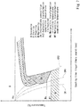
- Fig. 7 is a continuous cooling transformation (CCT) curve of S45C steel which is an example of the steel plates 51, 52.
- Line CR1 indicates an upper critical cooling rate.
- Line CR2 indicates a lower critical cooling rate.
- the upper critical cooling rate CR1 is defined as a minimum (lowest) cooling rate at which a composition having been cooled becomes only martensite.
- the lower critical cooling rate CR2 is defined as a minimum cooling rate required to cause the martensitic transformation to occur.
- the cooling rate is lower than the lower critical cooling rate CR2
- cooling is performed as slowly as possible, after the friction stirring.
- the spot welding portion 53 is cooled at a cooling rate CR which is equal to or higher than the upper critical cooling rate CR1 (although a case where the cooling rate CR is higher than the upper critical cooling rate CR1, is described, for easier understanding the description, the cooling rate CR may be equal to CR1).
- the forcible cooling is performed by use of the cooling device 20, as described above.
- the spot welding portion 53 is cooled to a second temperature T2 which is equal to or lower than a martensitic transformation completion temperature Mf. Since the spot welding portion 53 is quickly cooled to the second temperature T2, the spot welding portion 53 is actively hardened, and the martensite can be stably formed in the spot welding portion 53.
- the tool 10 is rotated at a second rotational speed N2, and a second pressing force F2 is applied by the tool 10 to the spot welding portion 53 (see Fig. 4D in addition to Figs. 6 and 7 ).
- the pressing force (second pressing force F2) applied to the spot welding portion 53 in the tempering step S24 is less than the pressing force (first pressing force F1) applied to the spot welding portion 53 in the friction stirring step S22. This makes it possible to mitigate an impact applied to the tool 10 when the tool 10 is re-plunged into the steel plates 51, 52.
- the rotational speed (second rotational speed N2) of the tool 10 in the tempering step S24 is higher than the rotational speed (first rotational speed N1) of the tool 10 in the friction stirring step S22.
- the second pressing force F2 is about 1/5 to 1/7 of the first pressing force F1
- the second rotational speed N2 is about three to five times as high as the first rotational speed N1.
- the temperature of the spot welding portion 53 is increased to a third temperature T3 which is lower than Ac1 transformation point (temperature at which austenite begins to be generated in the heating), and thereafter is decreased.
- the third temperature T3 is set to a value within a range of, for example, 550 to 650 degrees C.
- high-temperature tempering or thermal refining is performed, as an example of the tempering.
- the temperature of the spot welding portion 53 is decreased by pulling (drawing) out the tool 10.
- the spot welding portion 53 may be naturally cooled, or the fluid may be injected to the spot welding portion 53 by the cooling device 20 to forcibly cool the spot welding portion 53, as in the cooling step S23.
- the tempering step S24 By performing the tempering step S24, reduction of hardness and high toughness of the spot welding portion 53 can be realized. In addition, a residual stress generated in the cooling step S23 can be removed or reduced. Further, even in a case where the austenite composition is left after the cooling step S23, the composition can be stabilized by the tempering.
- the temperature of the spot welding portion 53, the heating speed (heating rate) for the spot welding portion 53, or the cooling rate for the spot welding portion 53 is required to meet a predetermined condition.
- the control unit 30 may decide the timing of beginning of each step, the timing of completion (ending) of each step, the timing of insertion of the tool 10, or the timing of pulling-up of the tool 10, while monitoring the detection value of a temperature sensor which detects the temperature of the spot welding portion 53.
- control unit 30 may give an operation command to each of the displacement driving unit 18 and the rotation driving unit 17 so that the displacement driving unit 18 and the rotation driving unit 17 operate or stop, according to the timings found in advance, without inputting the temperature information.
- Fig. 8 is a cross-sectional view of the spot welding portion 53 for which the spot welding step S2 is completed (specifically, the cross-sectional view of the spot welding portion 53 shown at the lower side of Fig. 3B ).
- the pin hole 53a is formed in the spot welding portion 53.
- the pin hole 53a is the plunge indentation of the pin 10b (see Fig. 3A ), and is the circular non-through hole.
- a ring-shaped protruding portion 53b is formed in the surface (upper surface in Fig. 8 ) of the steel plate 51, at a location with which the outer edge portion of the shoulder surface 10c (see Fig. 3A ) made a contact.
- a high-temperature heated region (zone) 53c which was heated at a temperature higher than the third temperature T3 in the tempering step S24, is formed at a location that is inward of the protruding portion 53b and is in the vicinity of the upper surface of the steel plate 51.
- a tempered region (zone) 53d is formed on the outer side of the high-temperature heated region 53c.
- the temperature of the tempered region 53d is increased up to the third temperature T3 in the tempering step S24, to realize reduction of hardness and high toughness.
- the tempered region 53d is in contact with an unaffected base metal interface of the steel plates 51, 52. Since the tempered region 53d with reduced hardness and increased toughness is in contact with the interface, joint strength, in particular, peel-off strength can be improved, as will be described later.
- the high-temperature heated region 53c was locally applied with a high pressing force, and became a main heat generating source of the friction heat.
- the tool 10 and the spot welding portion 53 are thermally contracted in the cooling step S23.
- a volume of the spot welding portion 53 changes due to a change in the composition. It is presumed that the high-temperature heated region 53c of Fig. 8 was generated because the amount of contraction of the tool 10 was less than the amount of contraction (including thermal contraction and change in the composition) of the spot welding portion 53 (pin hole 53a) in the cooling step S23.
- Figs. 9 to 11 are graphs showing characteristics of a joint of the steel plates manufactured by use of the friction stir spot welding method of the present embodiment.
- a joint manufactured without performing the cooling step S23 and the tempering step S24 is shown as a comparative example.
- Fig. 9 shows a hardness distribution of the spot welding portion 53 and a region which is close to the spot welding portion 53.
- a horizontal (lateral) axis indicates a distance (see Fig. 8 in addition to Fig. 9 ) in a lateral direction (direction perpendicular to the plate thickness direction) from the inner peripheral surface of the pin hole 53a, and a vertical (longitudinal) axis indicates Vickers hardness.
- a portion which is away at a first distance D or more, from the inner peripheral surface of the pin hole 53a there is no great difference in hardness between the present embodiment and the comparative example.
- this portion was an unaffected base metal (this portion was not stirred in the spot welding step S2 and noticeable composition change did not occur in this portion because input of the friction heat to this portion was less).
- this portion was stirred, or thermally affected by the friction heat and resulted in, for example, the change in the composition, even though this portion was not actually stirred.
- the hardness of this portion of the present embodiment is lower than that of this portion in the comparative example.
- Fig. 10 shows the joint strength.
- Fig. 10 shows a result of a tensile shear test at a left side and shows a result of a cross tension test at a right side.
- a vertical axis indicates a load required for a fracture.
- Fig. 11 is a load-stroke diagram in the cross tension test.
- the tensile shear strength and the peel-off strength are higher than those in the comparative example.
- the peel-off strength can be significantly improved.
- elongation of the spot welding portion 53 before the fracture occurs is greater in the present embodiment than in the comparative example.
- the spot welding portion 53 is plasticized by the friction heat, the spot welding portion 53 is quenched (hardened) by the cooling and then tempered by the tool 10. In this way, reduction of hardness and high toughness of the spot welding portion 53 can be realized. As a result, the joint strength can be improved.
- the tempering step S24 is required, the tool 10 used in the plunging step S21 and the friction stirring step S22 is used in the tempering step S24. Therefore, the plunging step S21, the friction stirring step S22, and the tempering step S24 can proceed smoothly in turn.
- the forcible cooling is performed after the plasticization, to make the cooling time as short as possible. This makes it possible to reduce the time required for the whole process. Therefore, productivity of the joint is high. Time T (see Fig. 6 ) required for the spot welding step S2 can be reduced to about several seconds.
- the spot welding portion 53 is cooled at the cooling rate CR which is equal to or higher than the upper critical cooling rate CR1 of the steel plates 51, 52. Therefore, the martensite can be stably formed in the spot welding portion 53, and high joint strength can be maintained. In addition, since the cooling time is reduced, productivity of the joint can be improved.
- the temperature of the spot welding portion 53 is decreased to a temperature which is equal to or lower than the martensitic transformation completion temperature Mf of the steel plates 51, 52. Therefore, the martensite can be stably formed in the spot welding portion 53, and high joint strength can be kept.
- the cooling step S23 includes the tool pulling-up step S23a and the fluid supply step S23b.
- the pull-up amount X of the tool 10 is set to be less than the pin-hole depth Y.
- the tempering step S24 is performed.
- the pull-up amount X of the tool 10 is set to be less than the pin-hole depth Y, a position deviation (position gap) between the tool 10 and the pin hole 53a can be reduced. Therefore, it becomes possible to prevent a situation in which the tool 10 undesirably collides with the steel plate 51 while the tool 10 is re-pressed against the spot welding portion 53.
- the rotational speed (second rotational speed N2) of the tool 10 in the tempering step S24 is set to be higher than the rotational speed (first rotational speed N1) of the tool 10 in the friction stirring step S22. This makes it possible to increase the speed of re-heating in the tempering step S24, and to reduce the time required for the tempering step S24.
- Fig. 12 is a graph showing a relation between the carbon content or tensile strength of the steel plate and the peel-off strength of the joint manufactured by the friction stir spot welding.
- a broken line in Fig. 12 indicates a case where the cooling step and the tempering step performed in the present embodiment are not performed.
- the peel-off strength can be effectively improved.
- the carbon content is less than 0.06%, the quenching hardness of the base metal is low, and the peel-off strength cannot be effectively improved.
- the spot welding portion 53 easily becomes hard and brittle after the friction stirring step, due to the increased hardenability.
- the toughness of the spot welding portion 53 can be increased. Therefore, the present embodiment is suitably applied to spot welding (spot joining) of the steel plates with a carbon content of 0.06% or more or tensile strength of 590MPa or higher.
- the peel-off strength can be improved by realizing reduction of hardness and high toughness of the spot welding portion 53. As a result, the relation between the carbon content/tensile strength and the peel-off strength of the joint in a conventional example can be improved.
- Embodiment 2 is different from Embodiment 1 in the configuration of a cooling device 70 and the procedure of a cooling step S72.
- this difference will be mainly described.
- the cooling device 70 includes a cooling medium passage 71 through which a cooling medium flows, a cooler 72 which cools the cooling medium, and a cooling medium feeding unit 73 which feeds the cooling medium with a pressure.
- the cooler 72 may be a heat exchanger (or heat radiator) which takes heat from the cooling medium by the heat exchange with ambient air.
- the cooling medium passage 71 may be a closed or open circuit.
- the cooling medium is preferably a liquid, but is not limited.
- a control unit 80 controls the cooling device 70 (in particular, the cooling medium feeing unit 73).
- the cooling medium passage 71 includes at least one of a first cooling medium passage 71a formed to pass through the inside of a tool 60 and configured to flow the cooling medium therethrough, and a second cooling medium passage 71b formed to pass through the inside of a support base 65 and configured to flow the cooling medium therethrough.
- a case where the cooling medium passage 71 includes the first cooling medium passage 71a and the second cooling medium passage 71b will be described.
- the first cooling medium passage 71a and the second cooling medium passage 72b may be connected in parallel with the cooler 72.
- the cooling medium passage 71 may branch into a passage leading to the tool 60 and a passage leading to the support base 65 at a location that is downstream of the cooler 72 and these two passages may be joined together at a location that is downstream of the tool 60 and the support base 65 and upstream of the cooler 72.
- the overall flow of the friction stir spot welding method is shown in Fig. 2 .
- the cooling step is different from that of Figs. 4C and 5 .
- the cooling step S72 of the present embodiment the tool 60 is not pulled (drawn) out, and the rotational speed of the tool 60 is reduced, or the rotation of the tool 60 is stopped.
- the cooling medium feeding unit 73 operates and the cooling medium is circulated through the cooling medium passage 71.
- the cooling medium flowing through the inside of the tool 60 and the inside of the support table 65 takes the heat from the spot welding portion 53, and the spot welding portion 53 is forcibly cooled.
- the cooling medium which has taken the heat from the spot welding portion 53 and has an increased temperature is cooled by the cooler 72, and the cooled cooling medium is supplied to the tool 60 and the support base 65.
- the present invention is not limited to the above-described embodiments, and the configurations may be changed, added or deleted.
- the forcible cooling in the cooling step is not essential, and natural cooling may be performed so long as a desired cooling rate can be obtained.
- the pull-up amount of the tool is set to be less than the pin-hole depth. In this way, break of the tool in the tempering step can be prevented.
- the number of the steel plates which are lapped to each other and spot-welded to each other may be three or more.
Landscapes
- Chemical & Material Sciences (AREA)
- Engineering & Computer Science (AREA)
- Mechanical Engineering (AREA)
- Physics & Mathematics (AREA)
- Thermal Sciences (AREA)
- Crystallography & Structural Chemistry (AREA)
- Materials Engineering (AREA)
- Metallurgy (AREA)
- Organic Chemistry (AREA)
- Pressure Welding/Diffusion-Bonding (AREA)
Abstract


Description
- The present invention relates to a method and device for friction stir spot welding.
- In some cases, a joint is manufactured by performing friction stir spot welding of a plurality of steel plates which are lapped to each other. During friction stirring, the temperature of a spot welding portion of the steel plates is raised to a temperature at which austenitic transformation occurs by friction heat. When a tool is pulled out (drawn out) of the steel plates, the temperature of the spot welding portion is decreased. If martensitic transformation occurs while the temperature is decreased, the spot welding portion is cured (hardened) and becomes brittle. This results in reduced joint strength.
-
Patent Literature 1 discloses that in a case where the temperature of the spot welding portion (portion to be welded) is increased up to a temperature that is equal to or higher than A3 transformation point, the rotational speed of the tool is reduced in a state in which the tool is inserted into a base metal, and the portion to be welded is gradually cooled. In a case where the temperature of the portion to be welded is decreased to A1 transformation point, the tool is pulled out (drawn out), and the portion to be welded is naturally cooled. By using this method, cooling is performed slowly to suppress formation of the martensite and suppress reduction of the joint strength. - Patent Literature 1: Japanese-Laid Open Patent Application Publication No.
2011-115842 - In a case where the steel plates have a high hardenability, long cooling time is required to prevent formation of the martensite. For example, in a case where the base metal is medium-high carbon steel or alloy steel, it is necessary to take several minutes to return the temperature of the spot welding portion, from the A3 transformation point to a room temperature, in order to prevent formation of the martensite.
- Therefore, the above-described method has a drawback of productivity. To improve the productivity, it is necessary to reduce the cooling time. However, in this case, the formation of the martensite cannot be suppressed. Therefore, it is difficult to keep high joint strength.
- An object of the present invention is to improve joint strength and productivity in a case where friction stir spot welding of steel plates is performed.
- To solve the above-described problem, according to the present invention, there is provided a method of performing friction stir spot welding of a plurality of steel plates, the method comprising the steps of: friction stirring a spot welding portion of the plurality of steel plates by pressing a tool against the spot welding portion while rotating the tool, to plasticize the spot welding portion by friction heat; cooling the spot welding portion to cause martensitic transformation to occur in the spot welding portion, after the step of friction stirring the spot welding portion; and tempering the spot welding portion by the friction heat by re-pressing the tool against the spot welding portion while rotating the tool, after the step of cooling the spot welding portion.
- In the description, the term "spot welding portion" is used to indicate a portion for which the friction stir spot welding is to be performed, a portion for which the friction stir spot welding is being performed, or a portion for which the friction stir spot welding has been performed, without distinguishing these portions from each other.
- In accordance with this method, after the spot welding portion has been plasticized by the friction heat, the spot welding portion is quenched (hardened) by the cooling, and then tempered by use of the tool. This makes it possible to realize reduction of hardness and high toughness of the spot welding portion, and improve the joint strength.
- Although the tempering step is required, the tool used in the friction stirring step is used in the tempering step. Therefore, the steps from the friction stirring step to the tempering step can proceed smoothly in turn. As a result, productivity of the joint can be increased.
- In the step of cooling the spot welding portion, the spot welding portion may be cooled at a cooling rate which is equal to or higher than an upper critical cooling rate of the plurality of steel plates.
- In accordance with this method, the martensite can be stably formed in the spot welding portion, and high joint strength can be kept. In addition, cooling time is reduced, and the productivity of the joint can be improved.
- In the step of cooling the spot welding portion, a temperature of the spot welding portion may be decreased to a temperature which is equal to or lower than a martensitic transformation completion temperature of the plurality of steel plates.
- In accordance with this method, the martensite can be stably formed in the spot welding portion, and high joint strength can be kept.
- The step of cooling the spot welding portion may include pulling up the tool to form a space between the tool and the spot welding portion, and the tool may be pulled up so that a pull-up amount of the tool is less than a pin hole depth.
- In accordance with this method, a position deviation (position gap) between the tool and the pin hole can be suppressed. Therefore, it becomes possible to prevent a situation in which the tool undesirably interferes with the steel plate while the tool is re-pressed against the spot welding portion in the tempering step. As a result, break of the tool can be prevented.
- In the step of tempering the spot welding portion, a temperature of the spot welding portion may be increased up to 550 to 650 degrees C and then decreased.
- In accordance with this method, since the spot welding portion is tempered at a high temperature, it becomes possible to suitably realize reduction of hardness and high toughness of the spot welding portion.
- In the step of tempering the spot welding portion, a rotational speed of the tool may be set to be higher than a rotational speed of the tool in the step of friction stirring the spot welding portion.
- In accordance with this method, the speed of re-heating in the tempering step is increased, and time required for the tempering step can be reduced.
- The plurality of steel plates may have a carbon content of 0.06% or more, or a tensile strength of 590MPa or higher.
- By performing the above method, it becomes possible to realize reduction of hardness and high toughness of the spot welding portion, and improve the joint strength. This is advantageous.
- According to another aspect of the present invention, there is provided a device for performing friction stir spot welding of a plurality of steel plates, the device comprising: a displacement driving unit which displaces a spot welding portion of the plurality of steel plates and a tool relative to each other; a rotation driving unit which rotates the tool; and a control unit, wherein the control unit performs a friction stirring step, in which the control unit causes the displacement driving unit and the rotation driving unit to operate to press the tool against the spot welding portion while rotating the tool, to plasticize the spot welding portion by friction heat, wherein the control unit performs a cooling step for cooling the spot welding portion, in which the control unit causes at least one of the displacement driving unit and the rotation driving unit to operate, to pull up the tool and/or reduce a rotational speed of the tool, and the control unit performs a tempering step for tempering the spot welding portion, in which the control unit causes the displacement driving unit and the rotation driving unit to operate to re-press the tool against the spot welding portion while rotating the tool.
- In accordance with the present invention, it becomes possible to improve joint strength and productivity in a case where friction stir spot welding of steel plates is performed.
-
-
Fig. 1 is a view schematically showing a friction stir spot welding device according toEmbodiment 1. -
Fig. 2 is a flowchart showing a friction stir spot welding method according toEmbodiment 1. -
Fig. 3A is a partially enlarged view ofFig. 1 , and showing a completion state of a positioning step.Fig. 3B is a view taken in the direction of arrow B ofFig. 3A , showing steel plates positioned with respect to the friction stir spot welding device, when viewed in a plate thickness direction. -
Fig. 4 shows a plunging step.Fig. 4B shows a friction stirring step.Fig. 4C shows a cooling step.Fig. 4D shows an tempering step. -
Fig. 5 is a flowchart showing the cooling step according toEmbodiment 1. -
Fig. 6 is a time chart of a spot welding step. -
Fig. 7 is a CCT curve of a steel plate. -
Fig. 8 is a view showing a completion state of the spot welding step. -
Fig. 9 is a graph showing a hardness distribution of a spot welding portion. -
Fig. 10 is a graph showing joint strength of the spot welding portion. -
Fig. 11 is a load-stroke diagram in a cross tension test conducted for the spot welding portion. -
Fig. 12 is a graph showing a relation between carbon content/tensile strength and joint strength of the steel plate. -
Fig. 13 is a view showing a cooling device of a friction stir spot welding device according toEmbodiment 2, and a cooling step according toEmbodiment 2. - Hereinafter, the embodiments will be described with reference to the drawings. Throughout the drawings, the same or corresponding constituents are designated by the same reference symbols and will not be described in detail repeatedly.
-
Fig. 1 is a view schematically showing a friction stirspot welding device 1 according toEmbodiment 1. In the present embodiment, the friction stirspot welding device 1 is configured to rotate and displace atool 10 with a substantially cylindrical shape, to perform friction stir spot welding of twosteel plates spot welding portions 53 are set or formed in the twosteel plates steel plates spot welding portions 53. - The friction stir
spot welding device 1 includes abase 11, amovable member 12, and atool retaining member 13. Themovable member 12 is mounted on the base 11 so that themovable member 12 is movable in the axis line direction of thetool retaining member 13. Thetool retaining member 13 is rotatable around its axis line. Thetool retaining member 13 is movable together with themovable member 12 in the axis line direction. Thetool 10 is detachably retained at the tip end portion of thetool retaining member 13 and placed coaxially with thetool retaining member 13. - Hereinafter, the axis line of the
tool retaining member 13 and the axis line of thetool 10 retained by thetool retaining member 13 will be referred to as "tool axis A". The extension direction of the tool axis A will be referred to as "tool axis direction". - The friction stir
spot welding device 1 includes aframe 14 and asupport base 15. Theframe 14 is secured to thebase 11. Theframe 14 extends from the base 11 while being curved in a L-shape or a C-shape. The tip end portion of theframe 14 faces thetool 10 in the tool axis direction. Thesupport base 15 is provided at the tip end portion of theframe 14, and supports thesteel plates 51, 52 (in particular, spot welding portion 53). - The friction stir
spot welding device 1 includes a linearmotion driving unit 16 and arotation driving unit 17. The linearmotion driving unit 16 linearly moves themovable member 12 in the tool axis direction. By this linear motion of themovable member 12, thetool 10 is displaced in the tool axis direction with respect to the twosteel plates support base 15. Therotation driving unit 17 rotates thetool retaining member 13 and thetool 10 around the tool axis A. The linearmotion driving unit 16 and therotation driving unit 17 are, for example, electric (electrically powered) motors. - The
base 11 is detachably mounted on the tip end portion of anarm 19a of an articulated (multi-joint)robot 19. When thearm 19a operates, thebase 11 is displaced with respect to a base (not shown) of the articulatedrobot 19, and thus thetool 10 is displaced with respect to thesteel plates arm 19a of the articulatedrobot 19 and the linearmotion driving unit 16 serve as adisplacement driving unit 18 which displace thetool 10 and thespot welding portion 53 of thesteel plates - The friction stir
spot welding device 1 includes acooling device 20 which cools thespot welding portion 53. In the present embodiment, thecooling device 20 includes anozzle 21 which injects a fluid. Thenozzle 21 is connected to afluid source 22 via apipe 23. Thepipe 23 is provided with a switchingunit 24 which performs switching between injection and non-injection of the fluid from thenozzle 21. For example, thefluid source 22 is a tank which stores the fluid in a pressure higher than an atmospheric pressure, and the switchingunit 24 is an electromagnetic on/off valve. In this case, when the electromagnetic on/off valve as the switchingunit 24 is opened, the fluid is injected from thenozzle 21, while when the electromagnetic on/off valve is closed, the injection of the fluid is stopped (ceased). Thenozzle 21 is provided at thebase 11. An injection opening of thenozzle 21 is directed toward the tip end portion of thetool retaining member 13. Thefluid source 22 may be mounted on the base 11 or may be located to be distant from thebase 11 outside thebase 11. - The friction stir
spot welding device 1 includes acontrol unit 30 which controls therotation driving unit 17, thedisplacement driving unit 18, and the cooling device 20 (in the present embodiment, in particular, the switching unit 24). Thecontrol unit 30 may be a single control unit with an integrated function, or a plurality of control units with distributed functions. Thecontrol unit 30 includes a processor, a volatile memory, a non-volatile memory, an I/O interface, or the like. In response to a command input via the I/O interface by an input device (e.g., a computer, a teaching pendant or an operation board (control panel)) which is not shown, the processor of thecontrol unit 30 performs calculations (computations) by use of the volatile memory based on an operation program stored in the non-volatile memory, and thecontrol unit 30 communicates with therotation driving unit 17, thedisplacement driving unit 18 and thecooling device 20 via the I/O interface. - The outline of the flow of the friction stir spot welding method performed by the friction stir
spot welding device 1 will be described.Fig. 2 is a flowchart showing the friction stir spot welding method according toEmbodiment 1. Initially, thesteel plates spot welding device 1 so that onespot welding portion 53 is supported on thesupport base 15 and faces thetool 10 in the tool axis direction (positioning step S1). In the positioning step S1, thearm 19a of the articulatedrobot 19 may be operated to displace thebase 11, thesteel plates base 11 by a workpiece transfer device (not shown), or the displacement of thebase 11 and the displacement of thesteel plates - Then, the friction stir spot welding is performed for one
spot welding portion 53 supported on the support base 15 (spot welding step S2). In the spot welding step S2 performed once, a plunging step S21, a friction stirring step S22, a cooling step S23, and a tempering step S24 are performed in this order. - When the spot welding step S2 is completed, the process returns to the positioning step S1. The
steel plates spot welding device 1 so that thespot welding portion 53 to be treated next is supported on thesupport base 15. By repeating the positioning step S1 and the spot welding step S2, thesteel plates spot welding portions 53. The friction stir spot welding method ends when a condition (e.g., predetermined number of spot welding steps S2 are completed, or a maintenance is needed) is met, although this is not shown in detail. -
Fig. 3A is an enlarged view ofFig. 1 , showing a state in which the positioning step S1 is completed. The twosteel plates support base 15 in a state in which a plate thickness direction and a lapping direction conform to the tool axis direction. Thesteel plate 52 is placed on the support surface of thesupport base 15, and thesteel plate 51 is lapped on thesteel plate 52. Thetool 10 includes acylindrical tool body 10a and apin 10b protruding from the center of thetool body 10a. Thepin 10b has a diameter smaller than that of thetool body 10a. Hereinafter, a ring-shaped surface which is the end surface in the tool axis direction, of thetool body 10a, and surrounds thepin 10b, will be referred to as "shoulder surface 10c". -
Fig. 3B is a view taken in the direction of arrow B ofFig. 3A , showing a state in which thesteel plates spot welding portions 53 shown inFig. 3B , thespot welding portion 53 shown at a lower side is thespot welding portion 53 which has gone through the spot welding step S2 (reference symbols spot welding portion 53 shown at a middle side is thespot welding portion 53 which does not go through spot welding step S2 yet, after the positioning step S1 has been completed. Thespot welding portion 53 shown at an upper side is thespot welding portion 53 which is a target for which the positioning step S1 and the spot welding step S2 are to be performed, after the spot welding step S2 for, for example, thespot welding portion 53 shown at the middle side has been completed. - As shown in
Figs. 4A and 4B , in the plunging step S21, thetool 10 is moved in the tool axis direction while rotating thetool 10 around the tool axis A. In this way, thetool 10 is plunged into thesteel plates - While the rotating
tool 10 is moved, initially, thepin 10b is pressed against the surface (upper surface inFigs. 4A and 4B ), of thesteel plate 51. A portion of thesteel plate 51 against which thepin 10b is pressed, is softened by friction heat. Since the portion of thesteel plate 51 is softened, thepin 10b is further moved in the tool axis direction, from the surface of thesteel plate 51. Thepin 10b is plunged into thesteel plate 51, penetrates thesteel plate 51, and reaches the surface (upper surface inFigs. 4A and 4B ) of thesteel plate 52. Likewise, a portion of thesteel plate 52 is softened by the friction heat. Thepin 10b is further moved in the tool axis direction from the surface of thesteel plate 52, and is plunged into thesteel plate 52. - The
tool 10 is moved until theshoulder surface 10c is pressed against the surface (upper surface inFigs. 4A and 4B ) of thesteel plate 51. In a state in which theshoulder surface 10c is pressed against thesteel plate 51, thepin 10b penetrates thesteel plate 51 and is plunged into thesteel plate 52. In the present embodiment, thepin 10b does not penetrate thesteel plate 52. - As shown in
Fig. 4B , in the friction stirring step S22, thetool 10 is pressed against (applies a pressing force to) thespot welding portion 53 while rotating thetool 10, to plasticize thespot welding portion 53 by the friction heat. Since thepin 10b has reached thesteel plate 52, thesteel plate 51 and thesteel plate 52 are kneaded and mixed with each other at the spot welding portion 53 (see cross-hatched region inFig. 4B ). - Note that the "pressing force" (pressure) applied by the
tool 10 to thesteel plates tool 10 to thesteel plate 51, except otherwise noted. - As shown in
Figs. 4C and5 , in the cooling step S23, thetool 10 is pulled (drawn) up, and thus aspace 54 is formed between thetool 10 and the spot welding portion 53 (tool pulling-up step S23a). Then, the fluid is poured (fed) into thespace 54 to forcibly cool the spot welding portion 53 (liquid supply step S23b). In the tool pulling-up step S23a, thetool 10 is moved in the tool axis direction and retracted from thespot welding portion 53. At this time, the rotation of thetool 10 may be stopped or may be continued. Further, thetool 10 may be rotated in a direction opposite to the rotation during the plunging step. In the fluid supply step S23b, thecooling device 20 operates. In the present embodiment, the fluid is injected from thenozzle 21. The fluid may be a liquid or a gas. In a case where the fluid is the gas, cooled air or an inactive (inert) gas such as nitrogen or argon can be suitably used. The inactive gas may also be cooled to have a temperature lower than that of ambient air. - As shown in
Fig. 4C , a pull-up amount X of thetool 10 is less than a pin-hole depth Y. Apin hole 53a is a plunge indentation of thepin 10b which is formed in thespot welding portion 53 when thepin 10b is pulled up. Thepin hole 53a is a circular non-through hole. The pin-hole depth Y is a length in the plate thickness direction (tool axis direction) from the upper edge of thepin hole 53a to the bottom surface of thepin hole 53a. The upper edge of thepin hole 53a corresponds to a portion with which a corner portion formed by the outer peripheral surface of thepin 10b and theshoulder surface 10c made a contact. - In a case where the pull-up amount X is less than the pin hole depth Y, the tip end of the
pin 10b stays at a location that is lower than the upper edge of thepin hole 53a. Theshoulder surface 10c is apart from and above thesteel plate 51. Thepin 10b is apart from and above the bottom surface of thepin hole 53a, and a part of thepin 10b is located within thepin hole 53a. A gap is formed between thepin 10b and the upper edge of thepin hole 53a. The fluid injected from thenozzle 21 flows through this gap and reaches the inside of thepin hole 53a. The inner peripheral surface of thepin hole 53a and the inside of thepin hole 53a can be forcibly cooled by this fluid. - As shown in
Fig. 4D , in the tempering step S24, thetool 10 is pressed against thespot welding portion 53 while rotating thetool 10, to perform tempering of thespot welding portion 53 by the friction heat. In the present embodiment, in the cooling step S23, thetool 10 is pulled (drawn) up from thespot welding portion 53 once. Therefore, in the tempering step S24, again, thetool 10 is moved in the tool axis direction and fitted into thepin hole 53a. In this state, thetool 10 is pressed against (applies a pressing force to) thespot welding portion 53. In this way, thespot welding portion 53 is re-heated by the friction heat. After the re-heating, thetool 10 is pulled (drawn) up. Thespot welding portion 53 is cooled. Thus, the spot welding step S2 performed once is completed. -
Fig. 6 is a time chart of the spot welding step S2. InFig. 6 , the temperature of thespot welding portion 53 is shown at an upper side, the rotational speed of thetool 10 is shown at a middle side, and the pressing force applied by thetool 10 to thespot welding portion 53 is shown at a lower side. - As shown in
Fig. 6 , during execution of the friction stirring step S22, thetool 10 is rotated at a first rotational speed N1 and a first pressing force F1 is applied to the spot welding portion 53 (seeFig. 4B in addition toFig. 6 ). The first rotational speed N1 and the first pressing force F1 have sufficient values, respectively to allow plasticization to occur in thespot welding portion 53. In the friction stirring step S22, the temperature of thespot welding portion 53 is increased up to a first temperature T1 which is equal to or higher than Ac3 transformation point (austenitic transformation completion temperature during heating), by the friction heat. Thus, in the friction stirring step S22, austenitic transformation occurs in thespot welding portion 53. -
Fig. 7 is a continuous cooling transformation (CCT) curve of S45C steel which is an example of thesteel plates - In a case where the cooling rate is lower than the lower critical cooling rate CR2, it is possible to prevent occurrence of the martensitic transformation during the cooling. Conventionally, to suppress hardening of the
spot welding portion 53, cooling is performed as slowly as possible, after the friction stirring. To effectively suppress the hardening of thespot welding portion 53, it is necessary to set the cooling rate to a value that is close to the lower critical cooling rate CR2. In that case, several minutes are required to return the temperature from the Ac3 transformation point to a room temperature. If thetool 10 remains to be inserted into thesteel plates spot welding portion 53 during this period. - In contrast, as shown in
Figs. 6 and7 , in the cooling step S23 of the present embodiment, thespot welding portion 53 is cooled at a cooling rate CR which is equal to or higher than the upper critical cooling rate CR1 (although a case where the cooling rate CR is higher than the upper critical cooling rate CR1, is described, for easier understanding the description, the cooling rate CR may be equal to CR1). For the purpose of rapid cooling, in the cooling step S23, the forcible cooling is performed by use of thecooling device 20, as described above. - In the cooling step S23, the
spot welding portion 53 is cooled to a second temperature T2 which is equal to or lower than a martensitic transformation completion temperature Mf. Since thespot welding portion 53 is quickly cooled to the second temperature T2, thespot welding portion 53 is actively hardened, and the martensite can be stably formed in thespot welding portion 53. - In the tempering step S24, the
tool 10 is rotated at a second rotational speed N2, and a second pressing force F2 is applied by thetool 10 to the spot welding portion 53 (seeFig. 4D in addition toFigs. 6 and7 ). The pressing force (second pressing force F2) applied to thespot welding portion 53 in the tempering step S24 is less than the pressing force (first pressing force F1) applied to thespot welding portion 53 in the friction stirring step S22. This makes it possible to mitigate an impact applied to thetool 10 when thetool 10 is re-plunged into thesteel plates tool 10 in the tempering step S24 is higher than the rotational speed (first rotational speed N1) of thetool 10 in the friction stirring step S22. This makes it possible to increase a speed at which thespot welding portion 53 is heated in the tempering step S24 and to reduce the time required for the tempering step S24. For example, the second pressing force F2 is about 1/5 to 1/7 of the first pressing force F1, and the second rotational speed N2 is about three to five times as high as the first rotational speed N1. - In the tempering step S24, the temperature of the
spot welding portion 53 is increased to a third temperature T3 which is lower than Ac1 transformation point (temperature at which austenite begins to be generated in the heating), and thereafter is decreased. The third temperature T3 is set to a value within a range of, for example, 550 to 650 degrees C. In the tempering step S24, high-temperature tempering or thermal refining is performed, as an example of the tempering. The temperature of thespot welding portion 53 is decreased by pulling (drawing) out thetool 10. Thespot welding portion 53 may be naturally cooled, or the fluid may be injected to thespot welding portion 53 by the coolingdevice 20 to forcibly cool thespot welding portion 53, as in the cooling step S23. By performing the tempering step S24, reduction of hardness and high toughness of thespot welding portion 53 can be realized. In addition, a residual stress generated in the cooling step S23 can be removed or reduced. Further, even in a case where the austenite composition is left after the cooling step S23, the composition can be stabilized by the tempering. - As described above, in the friction stirring step S22, the cooling step S23, and the tempering step S24, the temperature of the
spot welding portion 53, the heating speed (heating rate) for thespot welding portion 53, or the cooling rate for thespot welding portion 53 is required to meet a predetermined condition. Thecontrol unit 30 may decide the timing of beginning of each step, the timing of completion (ending) of each step, the timing of insertion of thetool 10, or the timing of pulling-up of thetool 10, while monitoring the detection value of a temperature sensor which detects the temperature of thespot welding portion 53. - By conducting an experiment many times while adjusting the rotational speeds and the pressing forces, the timings of beginning of the steps and the timings of completion (ending) of the steps, with which the temperature meets the above-described condition can be found in advance. Therefore, the
control unit 30 may give an operation command to each of thedisplacement driving unit 18 and therotation driving unit 17 so that thedisplacement driving unit 18 and therotation driving unit 17 operate or stop, according to the timings found in advance, without inputting the temperature information. -
Fig. 8 is a cross-sectional view of thespot welding portion 53 for which the spot welding step S2 is completed (specifically, the cross-sectional view of thespot welding portion 53 shown at the lower side ofFig. 3B ). When the spot welding step S2 is completed, thepin hole 53a is formed in thespot welding portion 53. Thepin hole 53a is the plunge indentation of thepin 10b (seeFig. 3A ), and is the circular non-through hole. A ring-shaped protrudingportion 53b is formed in the surface (upper surface inFig. 8 ) of thesteel plate 51, at a location with which the outer edge portion of theshoulder surface 10c (seeFig. 3A ) made a contact. - In the inner region of the
spot welding portion 53, a high-temperature heated region (zone) 53c which was heated at a temperature higher than the third temperature T3 in the tempering step S24, is formed at a location that is inward of the protrudingportion 53b and is in the vicinity of the upper surface of thesteel plate 51. A tempered region (zone) 53d is formed on the outer side of the high-temperatureheated region 53c. As described above, the temperature of the temperedregion 53d is increased up to the third temperature T3 in the tempering step S24, to realize reduction of hardness and high toughness. The temperedregion 53d is in contact with an unaffected base metal interface of thesteel plates region 53d with reduced hardness and increased toughness is in contact with the interface, joint strength, in particular, peel-off strength can be improved, as will be described later. - While the
tool 10 was pressed against thespot welding portion 53 in the tempering step S24, the high-temperatureheated region 53c was locally applied with a high pressing force, and became a main heat generating source of the friction heat. Thetool 10 and thespot welding portion 53 are thermally contracted in the cooling step S23. In particular, a volume of thespot welding portion 53 changes due to a change in the composition. It is presumed that the high-temperatureheated region 53c ofFig. 8 was generated because the amount of contraction of thetool 10 was less than the amount of contraction (including thermal contraction and change in the composition) of the spot welding portion 53 (pin hole 53a) in the cooling step S23. In other words, it is presumed that the pressing force applied by theshoulder surface 10c to thesteel plate 51 in the tempering step S24 became relatively larger, and thereby great friction heat was generated in the surface of thesteel plate 51. By making use of such a difference between the amount of contraction of thetool 10 and the amount of contraction of thespot welding portion 53, and by choosing a thermal expansion rate of thetool 10, the location of the friction heat generating source can be changed. -
Figs. 9 to 11 are graphs showing characteristics of a joint of the steel plates manufactured by use of the friction stir spot welding method of the present embodiment. A joint manufactured without performing the cooling step S23 and the tempering step S24 is shown as a comparative example. -
Fig. 9 shows a hardness distribution of thespot welding portion 53 and a region which is close to thespot welding portion 53. A horizontal (lateral) axis indicates a distance (seeFig. 8 in addition toFig. 9 ) in a lateral direction (direction perpendicular to the plate thickness direction) from the inner peripheral surface of thepin hole 53a, and a vertical (longitudinal) axis indicates Vickers hardness. In a portion which is away at a first distance D or more, from the inner peripheral surface of thepin hole 53a, there is no great difference in hardness between the present embodiment and the comparative example. It is considered that this portion was an unaffected base metal (this portion was not stirred in the spot welding step S2 and noticeable composition change did not occur in this portion because input of the friction heat to this portion was less). On the other hand, regarding a portion which is within the first distance D from the inner peripheral surface of thepin hole 53a, it is considered that this portion was stirred, or thermally affected by the friction heat and resulted in, for example, the change in the composition, even though this portion was not actually stirred. The hardness of this portion of the present embodiment is lower than that of this portion in the comparative example. -
Fig. 10 shows the joint strength.Fig. 10 shows a result of a tensile shear test at a left side and shows a result of a cross tension test at a right side. A vertical axis indicates a load required for a fracture.Fig. 11 is a load-stroke diagram in the cross tension test. As shown inFig. 10 , in the present embodiment, the tensile shear strength and the peel-off strength are higher than those in the comparative example. In particular, the peel-off strength can be significantly improved. As can be seen fromFig. 11 , elongation of thespot welding portion 53 before the fracture occurs is greater in the present embodiment than in the comparative example. - In the present embodiment, after the
spot welding portion 53 is plasticized by the friction heat, thespot welding portion 53 is quenched (hardened) by the cooling and then tempered by thetool 10. In this way, reduction of hardness and high toughness of thespot welding portion 53 can be realized. As a result, the joint strength can be improved. - Although the tempering step S24 is required, the
tool 10 used in the plunging step S21 and the friction stirring step S22 is used in the tempering step S24. Therefore, the plunging step S21, the friction stirring step S22, and the tempering step S24 can proceed smoothly in turn. In particular, in the present embodiment, the forcible cooling is performed after the plasticization, to make the cooling time as short as possible. This makes it possible to reduce the time required for the whole process. Therefore, productivity of the joint is high. Time T (seeFig. 6 ) required for the spot welding step S2 can be reduced to about several seconds. - In the cooling step S23, the
spot welding portion 53 is cooled at the cooling rate CR which is equal to or higher than the upper critical cooling rate CR1 of thesteel plates spot welding portion 53, and high joint strength can be maintained. In addition, since the cooling time is reduced, productivity of the joint can be improved. - In the cooling step S23, the temperature of the
spot welding portion 53 is decreased to a temperature which is equal to or lower than the martensitic transformation completion temperature Mf of thesteel plates spot welding portion 53, and high joint strength can be kept. - In the present embodiment, the cooling step S23 includes the tool pulling-up step S23a and the fluid supply step S23b. In the tool pulling-up step S23a, the pull-up amount X of the
tool 10 is set to be less than the pin-hole depth Y. After the cooling step S23, the tempering step S24 is performed. In a case where the pull-up amount X of thetool 10 is set to be less than the pin-hole depth Y, a position deviation (position gap) between thetool 10 and thepin hole 53a can be reduced. Therefore, it becomes possible to prevent a situation in which thetool 10 undesirably collides with thesteel plate 51 while thetool 10 is re-pressed against thespot welding portion 53. - The rotational speed (second rotational speed N2) of the
tool 10 in the tempering step S24 is set to be higher than the rotational speed (first rotational speed N1) of thetool 10 in the friction stirring step S22. This makes it possible to increase the speed of re-heating in the tempering step S24, and to reduce the time required for the tempering step S24. -
Fig. 12 is a graph showing a relation between the carbon content or tensile strength of the steel plate and the peel-off strength of the joint manufactured by the friction stir spot welding. A broken line inFig. 12 indicates a case where the cooling step and the tempering step performed in the present embodiment are not performed. In this case, when the carbon content is 0.06% and the tensile strength is 590MPa, the peel-off strength can be effectively improved. In a case where the carbon content is less than 0.06%, the quenching hardness of the base metal is low, and the peel-off strength cannot be effectively improved. In a case where the carbon content is more than 0.06%, thespot welding portion 53 easily becomes hard and brittle after the friction stirring step, due to the increased hardenability. This results in reduced peel-off strength. In the present embodiment, by performing the tempering step S24, the toughness of thespot welding portion 53 can be increased. Therefore, the present embodiment is suitably applied to spot welding (spot joining) of the steel plates with a carbon content of 0.06% or more or tensile strength of 590MPa or higher. In this case, as indicated by a solid line ofFig. 12 , the peel-off strength can be improved by realizing reduction of hardness and high toughness of thespot welding portion 53. As a result, the relation between the carbon content/tensile strength and the peel-off strength of the joint in a conventional example can be improved. -
Fig. 13 showsEmbodiment 2.Embodiment 2 is different fromEmbodiment 1 in the configuration of acooling device 70 and the procedure of a cooling step S72. Hereinafter, regardingEmbodiment 2, this difference will be mainly described. - As shown in
Fig. 13 , thecooling device 70 includes a coolingmedium passage 71 through which a cooling medium flows, a cooler 72 which cools the cooling medium, and a coolingmedium feeding unit 73 which feeds the cooling medium with a pressure. The cooler 72 may be a heat exchanger (or heat radiator) which takes heat from the cooling medium by the heat exchange with ambient air. The coolingmedium passage 71 may be a closed or open circuit. The cooling medium is preferably a liquid, but is not limited. Acontrol unit 80 controls the cooling device 70 (in particular, the cooling medium feeing unit 73). - The cooling
medium passage 71 includes at least one of a firstcooling medium passage 71a formed to pass through the inside of atool 60 and configured to flow the cooling medium therethrough, and a secondcooling medium passage 71b formed to pass through the inside of asupport base 65 and configured to flow the cooling medium therethrough. For example, a case where the coolingmedium passage 71 includes the firstcooling medium passage 71a and the secondcooling medium passage 71b will be described. In this case, the firstcooling medium passage 71a and the second cooling medium passage 72b may be connected in parallel with the cooler 72. In brief, the coolingmedium passage 71 may branch into a passage leading to thetool 60 and a passage leading to thesupport base 65 at a location that is downstream of the cooler 72 and these two passages may be joined together at a location that is downstream of thetool 60 and thesupport base 65 and upstream of the cooler 72. - In the present embodiment, the overall flow of the friction stir spot welding method is shown in
Fig. 2 . However, the cooling step is different from that ofFigs. 4C and5 . As shown inFig. 13 , in the cooling step S72 of the present embodiment, thetool 60 is not pulled (drawn) out, and the rotational speed of thetool 60 is reduced, or the rotation of thetool 60 is stopped. The coolingmedium feeding unit 73 operates and the cooling medium is circulated through the coolingmedium passage 71. Thus, the cooling medium flowing through the inside of thetool 60 and the inside of the support table 65 takes the heat from thespot welding portion 53, and thespot welding portion 53 is forcibly cooled. The cooling medium which has taken the heat from thespot welding portion 53 and has an increased temperature, is cooled by the cooler 72, and the cooled cooling medium is supplied to thetool 60 and thesupport base 65. - In this case, the pulling-up of the
tool 60 and the re-fitting of thetool 60 can be omitted. Therefore, the time required for the spot welding step S2 can be reduced. - The present invention is not limited to the above-described embodiments, and the configurations may be changed, added or deleted. For example, the forcible cooling in the cooling step is not essential, and natural cooling may be performed so long as a desired cooling rate can be obtained. In the case of the natural cooling, it is necessary to pull-up the tool from the steel plates. In that case, the pull-up amount of the tool is set to be less than the pin-hole depth. In this way, break of the tool in the tempering step can be prevented. Further, the number of the steel plates which are lapped to each other and spot-welded to each other may be three or more.
-
- 1
- friction stir spot welding device
- 10, 60
- tool
- 17
- rotation driving unit
- 18
- displacement driving unit
- 20, 70
- cooling device
- 30, 80
- control unit
- 51, 52
- steel plate
- 53
- spot welding portion
- 54
- space
- S22
- friction stirring step
- S23
- cooling step
- S23a
- tool pulling-up step
- S24
- tempering step
- CR1
- upper critical cooling rate
- Mf
- martensitic transformation completion temperature
- N1
- first rotational speed (rotational speed of tool in friction stirring step)
- N2
- second rotational speed (rotational speed of tool in tempering step)
- X
- pull-up amount of tool
- Y
- pin hole depth
Claims (8)
- A method of performing friction stir spot welding of a plurality of steel plates, the method comprising the steps of:friction stirring a spot welding portion of the plurality of steel plates by pressing a tool against the spot welding portion while rotating the tool, to plasticize the spot welding portion by friction heat;cooling the spot welding portion to cause martensitic transformation to occur in the spot welding portion, after the step of friction stirring the spot welding portion; andtempering the spot welding portion by the friction heat by re-pressing the tool against the spot welding portion while rotating the tool, after the step of cooling the spot welding portion.
- The method of performing friction stir spot welding according to claim 1,
wherein in the step of cooling the spot welding portion, the spot welding portion is cooled at a cooling rate which is equal to or higher than an upper critical cooling rate of the plurality of steel plates. - The method of performing friction stir spot welding according to claim 1 or 2,
wherein in the step of cooling the spot welding portion, a temperature of the spot welding portion is decreased to a temperature which is equal to or lower than a martensitic transformation completion temperature of the plurality of steel plates. - The method of performing friction stir spot welding according to any one of claims 1 to 3,
wherein the step of cooling the spot welding portion includes pulling up the tool to form a space between the tool and the spot welding portion, and
wherein the tool is pulled up so that a pull-up amount of the tool is less than a pin hole depth. - The method of performing friction stir spot welding according to any one of claims 1 to 4,
wherein in the step of tempering the spot welding portion, a temperature of the spot welding portion is increased up to 550 to 650 degrees C and then decreased. - The method of performing friction stir spot welding according to claim 5,
wherein in the step of tempering the spot welding portion, a rotational speed of the tool is set to be higher than a rotational speed of the tool in the step of friction stirring the spot welding portion. - The method of performing friction stir spot welding according to any one of claims 1 to 6,
wherein the plurality of steel plates have a carbon content of 0.06% or more, or a tensile strength of 590MPa or higher. - A device for performing friction stir spot welding of a plurality of steel plates, the device comprising:a displacement driving unit which displaces a spot welding portion of the plurality of steel plates and a tool relative to each other;a rotation driving unit which rotates the tool; anda control unit,wherein the control unit performs a friction stirring step, in which the control unit causes the displacement driving unit and the rotation driving unit to operate to press the tool against the spot welding portion while rotating the tool, to plasticize the spot welding portion by friction heat,wherein the control unit performs a cooling step for cooling the spot welding portion, in which the control unit causes at least one of the displacement driving unit and the rotation driving unit to operate, to pull up the tool and/or reduce a rotational speed of the tool, andwherein the control unit performs a tempering step for tempering the spot welding portion, in which the control unit causes the displacement driving unit and the rotation driving unit to operate to re-press the tool against the spot welding portion while rotating the tool.
Applications Claiming Priority (2)
| Application Number | Priority Date | Filing Date | Title |
|---|---|---|---|
| JP2016126342 | 2016-06-27 | ||
| PCT/JP2017/023392 WO2018003740A1 (en) | 2016-06-27 | 2017-06-26 | Friction stir spot welding method and friction stir spot welding device |
Publications (3)
| Publication Number | Publication Date |
|---|---|
| EP3476518A1 true EP3476518A1 (en) | 2019-05-01 |
| EP3476518A4 EP3476518A4 (en) | 2020-03-04 |
| EP3476518B1 EP3476518B1 (en) | 2021-08-04 |
Family
ID=60786297
Family Applications (1)
| Application Number | Title | Priority Date | Filing Date |
|---|---|---|---|
| EP17820095.2A Active EP3476518B1 (en) | 2016-06-27 | 2017-06-26 | Friction stir spot welding method and friction stir spot welding device |
Country Status (6)
| Country | Link |
|---|---|
| US (1) | US11135674B2 (en) |
| EP (1) | EP3476518B1 (en) |
| JP (1) | JP6309183B1 (en) |
| KR (1) | KR102170227B1 (en) |
| CN (1) | CN109070265B (en) |
| WO (1) | WO2018003740A1 (en) |
Families Citing this family (11)
| Publication number | Priority date | Publication date | Assignee | Title |
|---|---|---|---|---|
| EP3981537B1 (en) * | 2017-09-04 | 2025-03-12 | Kawasaki Jukogyo Kabushiki Kaisha | Method for operating double-action friction stir welding device, and double-action friction stir welding device |
| JP6971180B2 (en) * | 2018-03-19 | 2021-11-24 | 川崎重工業株式会社 | Friction joining device and its operation method |
| KR102477654B1 (en) | 2018-10-11 | 2022-12-14 | 카와사키 주코교 카부시키 카이샤 | Friction stir welding device, its operation method and joint structure |
| DE102020200472A1 (en) * | 2019-06-13 | 2020-12-17 | Sms Group Gmbh | Fixing a strip end section of a metal strip coil to an adjacent strip winding |
| JP7223651B2 (en) * | 2019-07-01 | 2023-02-16 | 川崎重工業株式会社 | Welding system and its operation method |
| CN112238289A (en) * | 2019-07-16 | 2021-01-19 | 中国科学院沈阳自动化研究所 | Wireless temperature acquisition system of friction stir welding robot |
| WO2021029088A1 (en) * | 2019-08-09 | 2021-02-18 | 日本軽金属株式会社 | Joining method |
| JP7524096B2 (en) * | 2021-02-08 | 2024-07-29 | 川崎重工業株式会社 | Method for controlling friction stir welding apparatus and friction stir welding apparatus |
| US11660700B2 (en) * | 2021-06-04 | 2023-05-30 | Dus Operating Inc. | Welding and deburring system with cryogenic cooling |
| MX2024002623A (en) * | 2021-08-31 | 2024-03-22 | Jfe Steel Corp | Friction stir spot welding joint, manufacturing method therefor, and friction stir spot welding method. |
| US12599987B2 (en) * | 2021-08-31 | 2026-04-14 | Jfe Steel Corporation | Friction stir spot welded joint and production method therefor, and friction stir spot welding method |
Family Cites Families (10)
| Publication number | Priority date | Publication date | Assignee | Title |
|---|---|---|---|---|
| US6780525B2 (en) * | 2001-12-26 | 2004-08-24 | The Boeing Company | High strength friction stir welding |
| US7121448B2 (en) * | 2003-08-29 | 2006-10-17 | General Electric Company | Friction stir welding apparatus and associated thermal management systems and methods |
| JP4867538B2 (en) | 2006-09-19 | 2012-02-01 | マツダ株式会社 | Friction welding method |
| CN101649376A (en) * | 2008-08-14 | 2010-02-17 | 江阴兴鼎石油管件有限公司 | Deformation heat treatment method of petroleum drill pipe friction welding joint |
| JP5391046B2 (en) * | 2009-12-07 | 2014-01-15 | 川崎重工業株式会社 | Friction stir welding apparatus and joining method thereof |
| KR20110115842A (en) | 2010-04-16 | 2011-10-24 | (주)신명엔지니어링 | Fire Protection Structure of Hull Compartment |
| WO2012081100A1 (en) * | 2010-12-16 | 2012-06-21 | 三菱重工業株式会社 | Friction stir spot welding device and member support therefor |
| JP5900922B2 (en) | 2012-03-14 | 2016-04-06 | 国立大学法人大阪大学 | Manufacturing method of steel |
| CN105592969B (en) * | 2013-09-30 | 2018-01-16 | 杰富意钢铁株式会社 | Friction stir welding method of structural steel and manufacturing method of joint joint of structural steel |
| US9833861B2 (en) | 2013-09-30 | 2017-12-05 | Jfe Steel Corporation | Friction stir welding method for steel sheets and method of manufacturing joint |
-
2017
- 2017-06-26 JP JP2017565330A patent/JP6309183B1/en not_active Expired - Fee Related
- 2017-06-26 EP EP17820095.2A patent/EP3476518B1/en active Active
- 2017-06-26 WO PCT/JP2017/023392 patent/WO2018003740A1/en not_active Ceased
- 2017-06-26 KR KR1020197000926A patent/KR102170227B1/en not_active Expired - Fee Related
- 2017-06-26 CN CN201780026858.7A patent/CN109070265B/en not_active Expired - Fee Related
- 2017-06-26 US US16/313,785 patent/US11135674B2/en active Active
Also Published As
| Publication number | Publication date |
|---|---|
| WO2018003740A1 (en) | 2018-01-04 |
| KR102170227B1 (en) | 2020-10-26 |
| JP6309183B1 (en) | 2018-04-11 |
| JPWO2018003740A1 (en) | 2018-06-28 |
| KR20190018479A (en) | 2019-02-22 |
| EP3476518A4 (en) | 2020-03-04 |
| US20190314927A1 (en) | 2019-10-17 |
| EP3476518B1 (en) | 2021-08-04 |
| US11135674B2 (en) | 2021-10-05 |
| CN109070265B (en) | 2021-09-28 |
| CN109070265A (en) | 2018-12-21 |
Similar Documents
| Publication | Publication Date | Title |
|---|---|---|
| EP3476518B1 (en) | Friction stir spot welding method and friction stir spot welding device | |
| KR101792176B1 (en) | Method and device for producing a metal component | |
| US7540402B2 (en) | Method for controlling weld metal microstructure using localized controlled cooling of seam-welded joints | |
| JP6075304B2 (en) | Hot press molding method and hot press molding apparatus | |
| US10851436B2 (en) | Method for joining steel rails with controlled weld heat input | |
| US20220143900A1 (en) | Method and apparatus for in-situ thermal management and heat treatment of additively manufacturing components | |
| CN101622365B (en) | Method for improving the performance of seam-welded joints using post-weld heat treatment | |
| EP2585621B1 (en) | Tailored properties by post hot forming processing | |
| KR20130102461A (en) | Method for producing custom made, welded sheet steel products to be warm formed and corresponding welded product | |
| US20080115863A1 (en) | Method for improving the performance of seam-welded joints using post-weld heat treatment | |
| Taysom et al. | Controlling martensite and pearlite formation with cooling rate and temperature control in rotary friction welding | |
| JPWO2019181360A1 (en) | Solid-phase bonding method and solid-phase bonding device for metal materials | |
| US9498814B2 (en) | Method and device for producing a shaped component | |
| Osten et al. | Softening of high-strength steel for laser assisted clinching | |
| RU2415951C2 (en) | Procedure and device for micro-processing alloy on base of iron and material produced on its base | |
| JP2010029920A (en) | Resistance welding method and resistance welding system of bar steel | |
| Brückner et al. | Hybrid laser manufacturing | |
| KR101254348B1 (en) | Heat treatment method in press-fit connection | |
| CN111438327A (en) | Mechanical connection method and device for automobile steel | |
| Mitelea et al. | Parameter influence on friction welding of dissimilar surface-carburized/volume-hardened alloyed steels | |
| Thangavel et al. | Analysis and optimization of the automated TIG welding process parameters on SS304 incorporating Taguchi optimization technique | |
| Mesquita et al. | Heat treating of hot-work tool steels | |
| CA2916123C (en) | Method and device for partially hardening semifinished products | |
| Habak et al. | A study of the influence of the metallurgical state on shear band and white layer generation in 100Cr6 steel: application to machining | |
| Ozlati et al. | Upset resistance welding of carbon steel to austenitic stainless steel narrow rods |
Legal Events
| Date | Code | Title | Description |
|---|---|---|---|
| STAA | Information on the status of an ep patent application or granted ep patent |
Free format text: STATUS: THE INTERNATIONAL PUBLICATION HAS BEEN MADE |
|
| PUAI | Public reference made under article 153(3) epc to a published international application that has entered the european phase |
Free format text: ORIGINAL CODE: 0009012 |
|
| STAA | Information on the status of an ep patent application or granted ep patent |
Free format text: STATUS: REQUEST FOR EXAMINATION WAS MADE |
|
| 17P | Request for examination filed |
Effective date: 20190125 |
|
| AK | Designated contracting states |
Kind code of ref document: A1 Designated state(s): AL AT BE BG CH CY CZ DE DK EE ES FI FR GB GR HR HU IE IS IT LI LT LU LV MC MK MT NL NO PL PT RO RS SE SI SK SM TR |
|
| AX | Request for extension of the european patent |
Extension state: BA ME |
|
| DAV | Request for validation of the european patent (deleted) | ||
| DAX | Request for extension of the european patent (deleted) | ||
| A4 | Supplementary search report drawn up and despatched |
Effective date: 20200131 |
|
| RIC1 | Information provided on ipc code assigned before grant |
Ipc: B23K 20/12 20060101AFI20200127BHEP Ipc: C21D 9/50 20060101ALI20200127BHEP Ipc: C21D 1/18 20060101ALI20200127BHEP Ipc: C21D 1/34 20060101ALI20200127BHEP |
|
| GRAP | Despatch of communication of intention to grant a patent |
Free format text: ORIGINAL CODE: EPIDOSNIGR1 |
|
| STAA | Information on the status of an ep patent application or granted ep patent |
Free format text: STATUS: GRANT OF PATENT IS INTENDED |
|
| INTG | Intention to grant announced |
Effective date: 20210218 |
|
| GRAS | Grant fee paid |
Free format text: ORIGINAL CODE: EPIDOSNIGR3 |
|
| GRAA | (expected) grant |
Free format text: ORIGINAL CODE: 0009210 |
|
| STAA | Information on the status of an ep patent application or granted ep patent |
Free format text: STATUS: THE PATENT HAS BEEN GRANTED |
|
| AK | Designated contracting states |
Kind code of ref document: B1 Designated state(s): AL AT BE BG CH CY CZ DE DK EE ES FI FR GB GR HR HU IE IS IT LI LT LU LV MC MK MT NL NO PL PT RO RS SE SI SK SM TR |
|
| REG | Reference to a national code |
Ref country code: GB Ref legal event code: FG4D |
|
| REG | Reference to a national code |
Ref country code: AT Ref legal event code: REF Ref document number: 1416480 Country of ref document: AT Kind code of ref document: T Effective date: 20210815 |
|
| REG | Reference to a national code |
Ref country code: CH Ref legal event code: EP |
|
| REG | Reference to a national code |
Ref country code: DE Ref legal event code: R096 Ref document number: 602017043522 Country of ref document: DE |
|
| REG | Reference to a national code |
Ref country code: IE Ref legal event code: FG4D |
|
| REG | Reference to a national code |
Ref country code: LT Ref legal event code: MG9D |
|
| REG | Reference to a national code |
Ref country code: NL Ref legal event code: MP Effective date: 20210804 |
|
| REG | Reference to a national code |
Ref country code: AT Ref legal event code: MK05 Ref document number: 1416480 Country of ref document: AT Kind code of ref document: T Effective date: 20210804 |
|
| PG25 | Lapsed in a contracting state [announced via postgrant information from national office to epo] |
Ref country code: BG Free format text: LAPSE BECAUSE OF FAILURE TO SUBMIT A TRANSLATION OF THE DESCRIPTION OR TO PAY THE FEE WITHIN THE PRESCRIBED TIME-LIMIT Effective date: 20211104 Ref country code: AT Free format text: LAPSE BECAUSE OF FAILURE TO SUBMIT A TRANSLATION OF THE DESCRIPTION OR TO PAY THE FEE WITHIN THE PRESCRIBED TIME-LIMIT Effective date: 20210804 Ref country code: LT Free format text: LAPSE BECAUSE OF FAILURE TO SUBMIT A TRANSLATION OF THE DESCRIPTION OR TO PAY THE FEE WITHIN THE PRESCRIBED TIME-LIMIT Effective date: 20210804 Ref country code: NO Free format text: LAPSE BECAUSE OF FAILURE TO SUBMIT A TRANSLATION OF THE DESCRIPTION OR TO PAY THE FEE WITHIN THE PRESCRIBED TIME-LIMIT Effective date: 20211104 Ref country code: PT Free format text: LAPSE BECAUSE OF FAILURE TO SUBMIT A TRANSLATION OF THE DESCRIPTION OR TO PAY THE FEE WITHIN THE PRESCRIBED TIME-LIMIT Effective date: 20211206 Ref country code: FI Free format text: LAPSE BECAUSE OF FAILURE TO SUBMIT A TRANSLATION OF THE DESCRIPTION OR TO PAY THE FEE WITHIN THE PRESCRIBED TIME-LIMIT Effective date: 20210804 Ref country code: ES Free format text: LAPSE BECAUSE OF FAILURE TO SUBMIT A TRANSLATION OF THE DESCRIPTION OR TO PAY THE FEE WITHIN THE PRESCRIBED TIME-LIMIT Effective date: 20210804 Ref country code: HR Free format text: LAPSE BECAUSE OF FAILURE TO SUBMIT A TRANSLATION OF THE DESCRIPTION OR TO PAY THE FEE WITHIN THE PRESCRIBED TIME-LIMIT Effective date: 20210804 Ref country code: SE Free format text: LAPSE BECAUSE OF FAILURE TO SUBMIT A TRANSLATION OF THE DESCRIPTION OR TO PAY THE FEE WITHIN THE PRESCRIBED TIME-LIMIT Effective date: 20210804 Ref country code: RS Free format text: LAPSE BECAUSE OF FAILURE TO SUBMIT A TRANSLATION OF THE DESCRIPTION OR TO PAY THE FEE WITHIN THE PRESCRIBED TIME-LIMIT Effective date: 20210804 |
|
| PG25 | Lapsed in a contracting state [announced via postgrant information from national office to epo] |
Ref country code: PL Free format text: LAPSE BECAUSE OF FAILURE TO SUBMIT A TRANSLATION OF THE DESCRIPTION OR TO PAY THE FEE WITHIN THE PRESCRIBED TIME-LIMIT Effective date: 20210804 Ref country code: LV Free format text: LAPSE BECAUSE OF FAILURE TO SUBMIT A TRANSLATION OF THE DESCRIPTION OR TO PAY THE FEE WITHIN THE PRESCRIBED TIME-LIMIT Effective date: 20210804 Ref country code: GR Free format text: LAPSE BECAUSE OF FAILURE TO SUBMIT A TRANSLATION OF THE DESCRIPTION OR TO PAY THE FEE WITHIN THE PRESCRIBED TIME-LIMIT Effective date: 20211105 |
|
| PG25 | Lapsed in a contracting state [announced via postgrant information from national office to epo] |
Ref country code: NL Free format text: LAPSE BECAUSE OF FAILURE TO SUBMIT A TRANSLATION OF THE DESCRIPTION OR TO PAY THE FEE WITHIN THE PRESCRIBED TIME-LIMIT Effective date: 20210804 |
|
| PG25 | Lapsed in a contracting state [announced via postgrant information from national office to epo] |
Ref country code: DK Free format text: LAPSE BECAUSE OF FAILURE TO SUBMIT A TRANSLATION OF THE DESCRIPTION OR TO PAY THE FEE WITHIN THE PRESCRIBED TIME-LIMIT Effective date: 20210804 |
|
| REG | Reference to a national code |
Ref country code: DE Ref legal event code: R097 Ref document number: 602017043522 Country of ref document: DE |
|
| PG25 | Lapsed in a contracting state [announced via postgrant information from national office to epo] |
Ref country code: SM Free format text: LAPSE BECAUSE OF FAILURE TO SUBMIT A TRANSLATION OF THE DESCRIPTION OR TO PAY THE FEE WITHIN THE PRESCRIBED TIME-LIMIT Effective date: 20210804 Ref country code: SK Free format text: LAPSE BECAUSE OF FAILURE TO SUBMIT A TRANSLATION OF THE DESCRIPTION OR TO PAY THE FEE WITHIN THE PRESCRIBED TIME-LIMIT Effective date: 20210804 Ref country code: RO Free format text: LAPSE BECAUSE OF FAILURE TO SUBMIT A TRANSLATION OF THE DESCRIPTION OR TO PAY THE FEE WITHIN THE PRESCRIBED TIME-LIMIT Effective date: 20210804 Ref country code: EE Free format text: LAPSE BECAUSE OF FAILURE TO SUBMIT A TRANSLATION OF THE DESCRIPTION OR TO PAY THE FEE WITHIN THE PRESCRIBED TIME-LIMIT Effective date: 20210804 Ref country code: CZ Free format text: LAPSE BECAUSE OF FAILURE TO SUBMIT A TRANSLATION OF THE DESCRIPTION OR TO PAY THE FEE WITHIN THE PRESCRIBED TIME-LIMIT Effective date: 20210804 Ref country code: AL Free format text: LAPSE BECAUSE OF FAILURE TO SUBMIT A TRANSLATION OF THE DESCRIPTION OR TO PAY THE FEE WITHIN THE PRESCRIBED TIME-LIMIT Effective date: 20210804 |
|
| PLBE | No opposition filed within time limit |
Free format text: ORIGINAL CODE: 0009261 |
|
| STAA | Information on the status of an ep patent application or granted ep patent |
Free format text: STATUS: NO OPPOSITION FILED WITHIN TIME LIMIT |
|
| 26N | No opposition filed |
Effective date: 20220506 |
|
| PGFP | Annual fee paid to national office [announced via postgrant information from national office to epo] |
Ref country code: IT Payment date: 20220627 Year of fee payment: 6 |
|
| PG25 | Lapsed in a contracting state [announced via postgrant information from national office to epo] |
Ref country code: SI Free format text: LAPSE BECAUSE OF FAILURE TO SUBMIT A TRANSLATION OF THE DESCRIPTION OR TO PAY THE FEE WITHIN THE PRESCRIBED TIME-LIMIT Effective date: 20210804 |
|
| PGFP | Annual fee paid to national office [announced via postgrant information from national office to epo] |
Ref country code: DE Payment date: 20220630 Year of fee payment: 6 |
|
| PG25 | Lapsed in a contracting state [announced via postgrant information from national office to epo] |
Ref country code: MC Free format text: LAPSE BECAUSE OF FAILURE TO SUBMIT A TRANSLATION OF THE DESCRIPTION OR TO PAY THE FEE WITHIN THE PRESCRIBED TIME-LIMIT Effective date: 20210804 |
|
| REG | Reference to a national code |
Ref country code: CH Ref legal event code: PL |
|
| REG | Reference to a national code |
Ref country code: BE Ref legal event code: MM Effective date: 20220630 |
|
| GBPC | Gb: european patent ceased through non-payment of renewal fee |
Effective date: 20220626 |
|
| PG25 | Lapsed in a contracting state [announced via postgrant information from national office to epo] |
Ref country code: LU Free format text: LAPSE BECAUSE OF NON-PAYMENT OF DUE FEES Effective date: 20220626 Ref country code: LI Free format text: LAPSE BECAUSE OF NON-PAYMENT OF DUE FEES Effective date: 20220630 Ref country code: IE Free format text: LAPSE BECAUSE OF NON-PAYMENT OF DUE FEES Effective date: 20220626 Ref country code: FR Free format text: LAPSE BECAUSE OF NON-PAYMENT OF DUE FEES Effective date: 20220630 Ref country code: CH Free format text: LAPSE BECAUSE OF NON-PAYMENT OF DUE FEES Effective date: 20220630 |
|
| PG25 | Lapsed in a contracting state [announced via postgrant information from national office to epo] |
Ref country code: GB Free format text: LAPSE BECAUSE OF NON-PAYMENT OF DUE FEES Effective date: 20220626 Ref country code: BE Free format text: LAPSE BECAUSE OF NON-PAYMENT OF DUE FEES Effective date: 20220630 |
|
| REG | Reference to a national code |
Ref country code: DE Ref legal event code: R119 Ref document number: 602017043522 Country of ref document: DE |
|
| PG25 | Lapsed in a contracting state [announced via postgrant information from national office to epo] |
Ref country code: HU Free format text: LAPSE BECAUSE OF FAILURE TO SUBMIT A TRANSLATION OF THE DESCRIPTION OR TO PAY THE FEE WITHIN THE PRESCRIBED TIME-LIMIT; INVALID AB INITIO Effective date: 20170626 |
|
| PG25 | Lapsed in a contracting state [announced via postgrant information from national office to epo] |
Ref country code: MK Free format text: LAPSE BECAUSE OF FAILURE TO SUBMIT A TRANSLATION OF THE DESCRIPTION OR TO PAY THE FEE WITHIN THE PRESCRIBED TIME-LIMIT Effective date: 20210804 Ref country code: DE Free format text: LAPSE BECAUSE OF NON-PAYMENT OF DUE FEES Effective date: 20240103 Ref country code: CY Free format text: LAPSE BECAUSE OF FAILURE TO SUBMIT A TRANSLATION OF THE DESCRIPTION OR TO PAY THE FEE WITHIN THE PRESCRIBED TIME-LIMIT Effective date: 20210804 |
|
| PG25 | Lapsed in a contracting state [announced via postgrant information from national office to epo] |
Ref country code: IT Free format text: LAPSE BECAUSE OF NON-PAYMENT OF DUE FEES Effective date: 20230626 |
|
| PG25 | Lapsed in a contracting state [announced via postgrant information from national office to epo] |
Ref country code: MT Free format text: LAPSE BECAUSE OF FAILURE TO SUBMIT A TRANSLATION OF THE DESCRIPTION OR TO PAY THE FEE WITHIN THE PRESCRIBED TIME-LIMIT Effective date: 20210804 |
|
| PG25 | Lapsed in a contracting state [announced via postgrant information from national office to epo] |
Ref country code: TR Free format text: LAPSE BECAUSE OF FAILURE TO SUBMIT A TRANSLATION OF THE DESCRIPTION OR TO PAY THE FEE WITHIN THE PRESCRIBED TIME-LIMIT Effective date: 20210804 |