EP3476515A2 - Soldering system - Google Patents
Soldering system Download PDFInfo
- Publication number
- EP3476515A2 EP3476515A2 EP18201946.3A EP18201946A EP3476515A2 EP 3476515 A2 EP3476515 A2 EP 3476515A2 EP 18201946 A EP18201946 A EP 18201946A EP 3476515 A2 EP3476515 A2 EP 3476515A2
- Authority
- EP
- European Patent Office
- Prior art keywords
- lead
- tool
- robot
- soldering
- vision system
- Prior art date
- Legal status (The legal status is an assumption and is not a legal conclusion. Google has not performed a legal analysis and makes no representation as to the accuracy of the status listed.)
- Granted
Links
Images


Classifications
-
- B—PERFORMING OPERATIONS; TRANSPORTING
- B23—MACHINE TOOLS; METAL-WORKING NOT OTHERWISE PROVIDED FOR
- B23K—SOLDERING OR UNSOLDERING; WELDING; CLADDING OR PLATING BY SOLDERING OR WELDING; CUTTING BY APPLYING HEAT LOCALLY, e.g. FLAME CUTTING; WORKING BY LASER BEAM
- B23K1/00—Soldering, e.g. brazing, or unsoldering
- B23K1/0008—Soldering, e.g. brazing, or unsoldering specially adapted for particular articles or work
- B23K1/0016—Soldering of electronic components
-
- B—PERFORMING OPERATIONS; TRANSPORTING
- B23—MACHINE TOOLS; METAL-WORKING NOT OTHERWISE PROVIDED FOR
- B23K—SOLDERING OR UNSOLDERING; WELDING; CLADDING OR PLATING BY SOLDERING OR WELDING; CUTTING BY APPLYING HEAT LOCALLY, e.g. FLAME CUTTING; WORKING BY LASER BEAM
- B23K1/00—Soldering, e.g. brazing, or unsoldering
- B23K1/005—Soldering by means of radiant energy
- B23K1/0056—Soldering by means of radiant energy soldering by means of beams, e.g. lasers, electron beams [EB]
-
- B—PERFORMING OPERATIONS; TRANSPORTING
- B23—MACHINE TOOLS; METAL-WORKING NOT OTHERWISE PROVIDED FOR
- B23K—SOLDERING OR UNSOLDERING; WELDING; CLADDING OR PLATING BY SOLDERING OR WELDING; CUTTING BY APPLYING HEAT LOCALLY, e.g. FLAME CUTTING; WORKING BY LASER BEAM
- B23K3/00—Tools, devices or special appurtenances for soldering, e.g. brazing, or unsoldering, not specially adapted for particular methods
- B23K3/08—Auxiliary devices therefor
- B23K3/087—Soldering or brazing jigs, fixtures or clamping means
-
- B—PERFORMING OPERATIONS; TRANSPORTING
- B23—MACHINE TOOLS; METAL-WORKING NOT OTHERWISE PROVIDED FOR
- B23K—SOLDERING OR UNSOLDERING; WELDING; CLADDING OR PLATING BY SOLDERING OR WELDING; CUTTING BY APPLYING HEAT LOCALLY, e.g. FLAME CUTTING; WORKING BY LASER BEAM
- B23K37/00—Auxiliary devices or processes, not specially adapted for a procedure covered by only one of the other main groups of this subclass
- B23K37/04—Auxiliary devices or processes, not specially adapted for a procedure covered by only one of the other main groups of this subclass for holding or positioning work
- B23K37/0426—Fixtures for other work
- B23K37/0435—Clamps
- B23K37/0443—Jigs
-
- B—PERFORMING OPERATIONS; TRANSPORTING
- B23—MACHINE TOOLS; METAL-WORKING NOT OTHERWISE PROVIDED FOR
- B23K—SOLDERING OR UNSOLDERING; WELDING; CLADDING OR PLATING BY SOLDERING OR WELDING; CUTTING BY APPLYING HEAT LOCALLY, e.g. FLAME CUTTING; WORKING BY LASER BEAM
- B23K2101/00—Articles made by soldering, welding or cutting
- B23K2101/36—Electric or electronic devices
- B23K2101/38—Conductors
-
- H—ELECTRICITY
- H01—ELECTRIC ELEMENTS
- H01R—ELECTRICALLY-CONDUCTIVE CONNECTIONS; STRUCTURAL ASSOCIATIONS OF A PLURALITY OF MUTUALLY-INSULATED ELECTRICAL CONNECTING ELEMENTS; COUPLING DEVICES; CURRENT COLLECTORS
- H01R43/00—Apparatus or processes specially adapted for manufacturing, assembling, maintaining, or repairing of line connectors or current collectors or for joining electric conductors
- H01R43/02—Apparatus or processes specially adapted for manufacturing, assembling, maintaining, or repairing of line connectors or current collectors or for joining electric conductors for soldered or welded connections
- H01R43/0221—Laser welding
Definitions
- Embodiments of the present disclosure relate to a soldering system, particularly, to a soldering system for soldering the first lead and the second lead together.
- the ends of the inserted first lead and the second lead should be aligned and brought into contact with each other. Consequently, before soldering, it is required to first detect whether the alignment tolerance between the first lead and the second lead is within a predetermined tolerance value (allowable tolerance value); and if the alignment tolerance between the first lead and the second lead is larger than the predetermined tolerance value, the soldering quality will be lowered, even will cause soldering failure. Moreover, before soldering, it is it is also ensured that end faces of the first lead and the second lead are in physical contact; and if there is a gap between the first lead and the second lead, this will also lower the soldering quality between the first lead and the second lead, even will cause soldering failure.
- a predetermined tolerance value allowable tolerance value
- the soldering operation between the first lead and the second lead is usually performed manually.
- the worker needs to visually align the first lead and the second lead, and then hold the aligned first lead and the second lead by hand or a pressing device, and finally use the laser head to solder the first lead and the first lead together.
- the two leads are soldered together.
- Such a manual soldering method is very inefficient, neither ensures that the alignment tolerance between the leads is within the allowable tolerance values, nor ensures that the end faces of the leads are in a physical contact, thereby lowering the soldering quality of the leads.
- An objective of the present disclosure is to solve at least one aspect of the above mentioned problems and disadvantages occurred in the prior art.
- a soldering system comprising: a first robot on which a first tool and a second tool are mounted; a second robot on which a laser solder head is mounted; a fixation device adapted to fix an electrical product with a first lead and a second lead to be soldered; and a vision system adapted to identify positions of the first lead and the second lead and detect an alignment tolerance between them.
- the first robot moves at least one of the first lead and the second lead by the first tool to reduce the alignment tolerance; when the alignment tolerance between the first lead and the second lead detected by the vision system is within the predetermined tolerance value, the first robot presses or holds the first lead and the second lead by the second tool; and when the alignment tolerance between the first lead and the second lead is within the predetermined tolerance value, and the first lead and the second lead have been pressed or held by the second tool, the second robot moves the laser solder head to a predetermined position under guidance of the vision system, and solders the first lead and the second lead together by the laser solder head.
- the first lead and the second lead are pressed or held by the second tool.
- the first robot is adapted to move at least one of the first lead and the second lead by the first tool under the guidance of the vision system, in order to reduce the alignment tolerance between the first lead and the second lead to the predetermined tolerance value.
- the vision system is integrated to and moved with the second robot so as to avoid interference between the vision system and the first robot and the second robot.
- the first robot has a rotary disc on which the first tool and the second tool are mounted, so that one of the first tool and the second tool is rotated to an operating position by rotating the rotary disc.
- an end face of the first lead and an end face of the second lead are in a physical contact with each other.
- the electrical product is an electrical connector comprising a housing, a first connecting piece having the first lead and a second connecting piece having the second lead, the first connecting piece and the second connecting piece being assembled to the housing.
- the soldering system determines a precise soldering position of the first lead and the second lead based on positions, shapes and sizes of the first lead and the second lead identified by the vision system; and the second robot is adapted to move the laser solder head to the precise soldering position under the guidance of the vision system.
- soldering method comprising steps of:
- the step S80 comprises steps of:
- a set of soldering system may automatically complete operation of soldering the first lead and the second lead together, thereby improving the efficiency of soldering the leads and increasing the soldering quality of the leads.
- a soldering system comprising: a first robot on which a first tool and a second tool are mounted; a second robot on which a laser solder head is mounted; a fixation device adapted to fix an electrical product with a first lead and a second lead to be soldered; and a vision system adapted to identify positions of the first lead and the second lead and detect an alignment tolerance between them.
- the first robot moves at least one of the first lead and the second lead by the first tool to reduce the alignment tolerance; when the alignment tolerance between the first lead and the second lead detected by the vision system is within the predetermined tolerance value, the first robot presses or holds the first lead and the second lead by the second tool; and when the alignment tolerance between the first lead and the second lead is within the predetermined tolerance value, and the first lead and the second lead have been pressed or held by the second tool, the second robot moves the laser solder head to a predetermined position under the guidance of the vision system, and solders the first lead and the second lead together by the laser solder head.
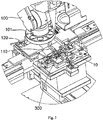
- Fig. 1 shows an illustrative perspective view of a soldering system according to an exemplary embodiment of the present disclosure.
- the soldering system mainly includes a first robot 100, a second robot 200, a fixation device 300 and a vision system 210.
- Fig. 2 shows a partial enlarged schematic view of the soldering system as shown in Fig. 1 .
- a first tool 110 and a second tool 120 are mounted on the first robot 100.
- a laser solder head 220 is mounted on the second robot 200.
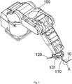
- Fig. 3 shows an illustrative perspective view of a first robot of the soldering system as shown in Fig. 1 ; and Fig. 4 shows an enlarged schematic view of an area A as shown in Fig. 3 .
- the fixation device 300 is adapted to fix an electrical product 10 with a first lead 11 and a second lead 12 to be soldered.
- the vision system 210 is adapted to identify positions of the first lead 11 and the second lead 12 and detect an alignment tolerance between them.
- the first robot 100 moves at least one of the first lead 11 and the second lead 12 by the first tool 110 to reduce the alignment tolerance.
- the first robot 100 presses or holds the first lead 11 and the second lead 12 by the second tool 120.
- the second robot 200 moves the laser solder head 220 to a predetermined position under the guidance of the vision system 210, and solders the first lead 11 and the second lead 12 together by the laser solder head 220.
- the first lead 11 and the second lead 12 are pressed or held by the second tool 120.
- the first robot 100 is adapted to move at least one of the first lead 11 and the second lead 12 by the first tool 110 under the guidance of the vision system 210, in order to reduce the alignment tolerance between the first lead 11 and the second lead 12 to the predetermined tolerance value.
- the vision system 210 is integrated to and moved with the second robot 200 so as to avoid interference between the vision system 210 and the first robot 100 and the second robot 200.
- the present disclosure is not limited to this, and the vision system 210 may be separately mounted above the fixation device 300, as long as no interference occurs between the vision system 210 and the first robot 100 and the second robot 200.
- the first robot 10 has a rotary disc 101 on which the first tool 110 and the second tool 120 are mounted. Accordingly, by rotating the rotary disc 101, one of the first tool 100 and the second tool 200 is rotated to an operating position.
- the electrical product 10 is an electrical connector that may comprise a housing 13, a first connecting piece having the first lead 11 and a second connecting piece having the second lead 12. The first connecting piece and the second connecting piece are assembled to the housing 13.
- the soldering system may determine a precise soldering position of the first lead 11 and the second lead 12 based on positions, shapes and sizes of the first lead 11 and the second lead 12 identified by the vision system 210.
- the second robot 200 is adapted to move the laser solder head 220 to the precise soldering position under the guidance of the vision system 210. In this way, the first lead 11 and the second lead 12 may be precisely soldered together.
- soldering method according to an exemplary embodiment of the present disclosure will be illustrated hereinafter with reference to Figs. 1-4 , the soldering method comprising the following steps:
- the step S80 may comprise:
Landscapes
- Engineering & Computer Science (AREA)
- Mechanical Engineering (AREA)
- Physics & Mathematics (AREA)
- Optics & Photonics (AREA)
- Electric Connection Of Electric Components To Printed Circuits (AREA)
- Laser Beam Processing (AREA)
Abstract
Description
- This application claims the benefit of Chinese Patent Application No.
201711007570.3 filed on October 25, 2017 - Embodiments of the present disclosure relate to a soldering system, particularly, to a soldering system for soldering the first lead and the second lead together.
- In the technical field of manufacturing a connector, it is desired, generally, to insert a first lead and a second lead into a housing from both sides of the housing, respectively, and then to solder ends of the inserted first lead and the second lead together.
- In order to ensure the soldering quality, the ends of the inserted first lead and the second lead should be aligned and brought into contact with each other. Consequently, before soldering, it is required to first detect whether the alignment tolerance between the first lead and the second lead is within a predetermined tolerance value (allowable tolerance value); and if the alignment tolerance between the first lead and the second lead is larger than the predetermined tolerance value, the soldering quality will be lowered, even will cause soldering failure. Moreover, before soldering, it is it is also ensured that end faces of the first lead and the second lead are in physical contact; and if there is a gap between the first lead and the second lead, this will also lower the soldering quality between the first lead and the second lead, even will cause soldering failure.
- In the relevant art, the soldering operation between the first lead and the second lead is usually performed manually. Generally, the worker needs to visually align the first lead and the second lead, and then hold the aligned first lead and the second lead by hand or a pressing device, and finally use the laser head to solder the first lead and the first lead together. The two leads are soldered together. Such a manual soldering method is very inefficient, neither ensures that the alignment tolerance between the leads is within the allowable tolerance values, nor ensures that the end faces of the leads are in a physical contact, thereby lowering the soldering quality of the leads.
- An objective of the present disclosure is to solve at least one aspect of the above mentioned problems and disadvantages occurred in the prior art.
- According to an aspect of the present disclosure, there is provided a soldering system, comprising: a first robot on which a first tool and a second tool are mounted; a second robot on which a laser solder head is mounted; a fixation device adapted to fix an electrical product with a first lead and a second lead to be soldered; and a vision system adapted to identify positions of the first lead and the second lead and detect an alignment tolerance between them. When the alignment tolerance between the first lead and the second lead detected by the vision system is larger than a predetermined tolerance value, the first robot moves at least one of the first lead and the second lead by the first tool to reduce the alignment tolerance; when the alignment tolerance between the first lead and the second lead detected by the vision system is within the predetermined tolerance value, the first robot presses or holds the first lead and the second lead by the second tool; and when the alignment tolerance between the first lead and the second lead is within the predetermined tolerance value, and the first lead and the second lead have been pressed or held by the second tool, the second robot moves the laser solder head to a predetermined position under guidance of the vision system, and solders the first lead and the second lead together by the laser solder head.
- According to an exemplary embodiment of the present disclosure, when the alignment tolerance between the first lead and the second lead is detected by the vision system, the first lead and the second lead are pressed or held by the second tool.
- According to a further exemplary embodiment of the present disclosure, the first robot is adapted to move at least one of the first lead and the second lead by the first tool under the guidance of the vision system, in order to reduce the alignment tolerance between the first lead and the second lead to the predetermined tolerance value.
- According to a further exemplary embodiment of the present disclosure, the vision system is integrated to and moved with the second robot so as to avoid interference between the vision system and the first robot and the second robot.
- According to a further exemplary embodiment of the present disclosure, the first robot has a rotary disc on which the first tool and the second tool are mounted, so that one of the first tool and the second tool is rotated to an operating position by rotating the rotary disc.
- According to a further exemplary embodiment of the present disclosure, when the first lead and the second lead are pressed or held by the second tool, an end face of the first lead and an end face of the second lead are in a physical contact with each other.
- According to a further exemplary embodiment of the present disclosure, the electrical product is an electrical connector comprising a housing, a first connecting piece having the first lead and a second connecting piece having the second lead, the first connecting piece and the second connecting piece being assembled to the housing.
- According to a further exemplary embodiment of the present disclosure, the soldering system determines a precise soldering position of the first lead and the second lead based on positions, shapes and sizes of the first lead and the second lead identified by the vision system; and the second robot is adapted to move the laser solder head to the precise soldering position under the guidance of the vision system.
- According to another aspect of the present disclosure, there is provided a soldering method, comprising steps of:
- S10: providing the soldering system;
- S20: completing an assembly of the electrical product and fixing the electrical product on the fixation device;
- S30: pressing or holding the first lead and the second lead of the electrical product to be soldered by the second tool of the first robot;
- S40: detecting the alignment tolerance between the first lead and the second lead by the vision system, and
- if the detected alignment tolerance is larger than the predetermined tolerance value, then
- S50: releasing the first lead and the second lead by putting the second tool back off, and moving at least one of the first lead and the second lead by the first tool to reduce the alignment tolerance between the first lead and the second lead;
- S60: removing the first tool away from the first lead and the second lead and pressing or holding the first lead and the second lead by the second tool; and S70: back to step S40; and
- if the detected alignment tolerance is within the predetermined tolerance value, then
S80: moving the laser solder head to the precise soldering position under the guidance of the vision system by the second robot, and soldering the first lead and the second lead together by the laser solder head.
- if the detected alignment tolerance is larger than the predetermined tolerance value, then
- According to an exemplary embodiment of the present disclosure, the step S80 comprises steps of:
- S81: identifying positions, shapes and sizes of the first lead and the second lead by the vision system, and determining the precise soldering position of the first lead with the second lead based on the identified positions, shapes and sizes;
- S82: moving the laser solder head to the precise soldering position under the guidance of the vision system by the second robot; and
- S83: activating the laser solder head to solder the first lead and the second lead together.
- In the above exemplary embodiments of the present disclosure, a set of soldering system may automatically complete operation of soldering the first lead and the second lead together, thereby improving the efficiency of soldering the leads and increasing the soldering quality of the leads.
- Other objectives and advantages of the present disclosure will become apparent from the following description of the present disclosure when taken in conjunction with the accompanying drawings, and may give a comprehensive understanding of the present disclosure.
- The above and other features of the present disclosure will become more apparent by describing in detail exemplary embodiments thereof with reference to the accompanying drawings, in which:
-
Fig. 1 shows an illustrative perspective view of a soldering system according to an exemplary embodiment of the present disclosure; -
Fig. 2 shows a partial enlarged schematic view of the soldering system as shown inFig. 1 ; -
Fig. 3 shows an illustrative perspective view of a first robot of the soldering system as shown inFig. 1 ; and -
Fig. 4 shows an enlarged schematic view of an area A as shown inFig. 3 . - The technical solution of the present disclosure will be described hereinafter in further detail with reference to the following embodiments, taken in conjunction with the accompanying drawings. In the specification, the same or similar reference numerals indicate the same or similar parts. The description of the embodiments of the present disclosure hereinafter with reference to the accompanying drawings is intended to explain the general inventive concept of the present disclosure, and should not be constructed as a limitation to the present disclosure.
- In addition, in the following detailed description, for the sake of explanation, numerous specific details are set forth in order to provide a thorough understanding of the disclosed embodiments. It will be apparent, however, one or more embodiments may also be practiced without these specific details. In other instances, well-known structures and devices are illustrated schematically in order to simplify the drawing.
- According to a general technical concept of the present disclosure, there is provided a soldering system, comprising: a first robot on which a first tool and a second tool are mounted; a second robot on which a laser solder head is mounted; a fixation device adapted to fix an electrical product with a first lead and a second lead to be soldered; and a vision system adapted to identify positions of the first lead and the second lead and detect an alignment tolerance between them. When the alignment tolerance between the first lead and the second lead detected by the vision system is larger than a predetermined tolerance value, the first robot moves at least one of the first lead and the second lead by the first tool to reduce the alignment tolerance; when the alignment tolerance between the first lead and the second lead detected by the vision system is within the predetermined tolerance value, the first robot presses or holds the first lead and the second lead by the second tool; and when the alignment tolerance between the first lead and the second lead is within the predetermined tolerance value, and the first lead and the second lead have been pressed or held by the second tool, the second robot moves the laser solder head to a predetermined position under the guidance of the vision system, and solders the first lead and the second lead together by the laser solder head.
-
Fig. 1 shows an illustrative perspective view of a soldering system according to an exemplary embodiment of the present disclosure. - As shown in
Fig. 1 , in an illustrated embodiment, the soldering system mainly includes afirst robot 100, asecond robot 200, afixation device 300 and avision system 210. -
Fig. 2 shows a partial enlarged schematic view of the soldering system as shown inFig. 1 . - As shown in
Figs. 1 and2 , in an illustrated embodiment, afirst tool 110 and asecond tool 120 are mounted on thefirst robot 100. Alaser solder head 220 is mounted on thesecond robot 200. -
Fig. 3 shows an illustrative perspective view of a first robot of the soldering system as shown inFig. 1 ; andFig. 4 shows an enlarged schematic view of an area A as shown inFig. 3 . - As shown in
Figs. 1-4 , in an illustrated embodiment, thefixation device 300 is adapted to fix anelectrical product 10 with afirst lead 11 and asecond lead 12 to be soldered. Thevision system 210 is adapted to identify positions of thefirst lead 11 and thesecond lead 12 and detect an alignment tolerance between them. - As shown in
Figs. 1-4 , in an illustrated embodiment, when the alignment tolerance between thefirst lead 11 and thesecond lead 12 detected by thevision system 210 is larger than a predetermined tolerance value, thefirst robot 100 moves at least one of thefirst lead 11 and thesecond lead 12 by thefirst tool 110 to reduce the alignment tolerance. - As shown in
Figs. 1-4 , in an illustrated embodiment, when the alignment tolerance between thefirst lead 11 and thesecond lead 12 detected by thevision system 210 is within the predetermined tolerance value, thefirst robot 100 presses or holds thefirst lead 11 and thesecond lead 12 by thesecond tool 120. - As shown in
Figs. 1-4 , in an illustrated embodiment, when the alignment tolerance between thefirst lead 11 and thesecond lead 12 is within the predetermined tolerance value, and thefirst lead 11 and thesecond lead 12 have been pressed or held by thesecond tool 120, thesecond robot 200 moves thelaser solder head 220 to a predetermined position under the guidance of thevision system 210, and solders thefirst lead 11 and thesecond lead 12 together by thelaser solder head 220. - As shown in
Figs. 1-4 , in an illustrated embodiment, when the alignment tolerance between thefirst lead 11 and thesecond lead 12 is detected by thevision system 210, thefirst lead 11 and thesecond lead 12 are pressed or held by thesecond tool 120. - As shown in
Figs. 1-4 , in an illustrated embodiment, thefirst robot 100 is adapted to move at least one of thefirst lead 11 and thesecond lead 12 by thefirst tool 110 under the guidance of thevision system 210, in order to reduce the alignment tolerance between thefirst lead 11 and thesecond lead 12 to the predetermined tolerance value. - As shown in
Figs. 1-4 , in an illustrated embodiment, thevision system 210 is integrated to and moved with thesecond robot 200 so as to avoid interference between thevision system 210 and thefirst robot 100 and thesecond robot 200. However, the present disclosure is not limited to this, and thevision system 210 may be separately mounted above thefixation device 300, as long as no interference occurs between thevision system 210 and thefirst robot 100 and thesecond robot 200. - As shown in
Figs. 1-4 , in an illustrated embodiment, thefirst robot 10 has arotary disc 101 on which thefirst tool 110 and thesecond tool 120 are mounted. Accordingly, by rotating therotary disc 101, one of thefirst tool 100 and thesecond tool 200 is rotated to an operating position. - As shown in
Figs. 1-4 , in an illustrated embodiment, when thefirst lead 11 and thesecond lead 12 are pressed or held by thesecond tool 120, an end face of thefirst lead 11 and an end face of thesecond lead 12 are in a physical contact with each other. - As shown in
Figs. 1-4 , in an illustrated embodiment, theelectrical product 10 is an electrical connector that may comprise ahousing 13, a first connecting piece having thefirst lead 11 and a second connecting piece having thesecond lead 12. The first connecting piece and the second connecting piece are assembled to thehousing 13. - As shown in
Figs. 1-4 , in an illustrated embodiment, the soldering system may determine a precise soldering position of thefirst lead 11 and thesecond lead 12 based on positions, shapes and sizes of thefirst lead 11 and thesecond lead 12 identified by thevision system 210. Thesecond robot 200 is adapted to move thelaser solder head 220 to the precise soldering position under the guidance of thevision system 210. In this way, thefirst lead 11 and thesecond lead 12 may be precisely soldered together. - A soldering method according to an exemplary embodiment of the present disclosure will be illustrated hereinafter with reference to
Figs. 1-4 , the soldering method comprising the following steps: - S10: providing the above-mentioned soldering system;
- S20: completing an assembly of the
electrical product 10 and fixing theelectrical product 10 on thefixation device 300; - S30: pressing or holding the
first lead 11 and thesecond lead 12 of theelectrical product 10 to be soldered by thesecond tool 120 of thefirst robot 100; - S40: detecting the alignment tolerance between the
first lead 11 and thesecond lead 12 by thevision system 210, and,- if the detected alignment tolerance is larger than the predetermined tolerance value, then
- S50: releasing the
first lead 11 and thesecond lead 12 by putting thesecond tool 120 back off, and moving at least one of thefirst lead 11 and thesecond lead 12 by thefirst tool 110 to reduce the alignment tolerance between thefirst lead 11 and thesecond lead 12; - S60: removing the
first tool 110 away from thefirst lead 11 and thesecond lead 12 and pressing or holding thefirst lead 11 and thesecond lead 12 by thesecond tool 120; and - S70: back to step S40;; and
- S50: releasing the
- if the detected alignment tolerance is within the predetermined tolerance value, then
S80: moving thelaser solder head 220 to the precise soldering position under guidance of thevision system 210 by thesecond robot 200, and soldering thefirst lead 11 and thesecond lead 12 together by thelaser solder head 220.
- if the detected alignment tolerance is larger than the predetermined tolerance value, then
- In an exemplary embodiment of the present disclosure, the step S80 may comprise:
- S81: identifying the positions, shapes and sizes of the
first lead 11 and thesecond lead 12 by thevision system 210, and determining the precise soldering position of thefirst lead 11 and thesecond lead 12 based on the identified positions, shapes and sizes; - S82: moving the
laser solder head 220 to the precise soldering position under the guidance of thevision system 210 by thesecond robot 200; and - S83: activating the
laser solder head 220 to solder thefirst lead 11 and thesecond lead 12 together. - It should be appreciated by those skilled in the art that the above embodiments are intended to be illustrative, modifications may be made to the above embodiments by those skilled in the art, and structures described in various embodiments may be freely combined without having structural and principle conflict.
- Although the present disclosure has been described with reference to the attached drawings, the embodiments disclosed in the drawings are intended to illustrate the preferred embodiments of the present disclosure, but should not be constructed as a limitation to the present disclosure.
- Although some embodiments of the general concept of the present disclosure has been shown and described, it would be appreciated by those skilled in the art that modifications may be made to these embodiments without departing from the principle and spirit of the present disclosure, the scope of which is defined in the claims and their equivalents.
- It should be noted that term "comprising" or "including" should be understood as not excluding other elements or steps, and term "a" or "an" should be understood as not excluding plural elements or steps. Further, any reference numerals in claims should not be understood as a limitation to the present disclosure.
Claims (10)
- A soldering system, comprising:a first robot (100) on which a first tool (110) and a second tool (120)are mounted;a second robot (200) on which a laser solder head (220) is mounted;a fixation device (300) adapted to fix an electrical product (10) with a first lead (11) and a second lead (12) to be soldered; anda vision system (210) adapted to identify positions of the first lead (11) and the second lead (11) and detect an alignment tolerance between them;characterized in that:when the alignment tolerance between the first lead (11) and the second lead (12) detected by the vision system (210) is larger than a predetermined tolerance value, the first robot (100) moves at least one of the first lead (11) and the second lead (12) by the first tool (110) to reduce the alignment tolerance;when the alignment tolerance between the first lead (11) and the second lead (12) detected by the vision system (210) is within the predetermined tolerance value, the first robot (100) presses or holds the first lead (11) and the second lead (12) by the second tool (120); andwhen the alignment tolerance between the first lead (11) and the second lead (12) is within the predetermined tolerance value, and the first lead (11) and the second lead (12) have been pressed or held by the second tool (120), the second robot (200) moves the laser solder head (220) to a predetermined position under guidance of the vision system, and solders the first lead (11) and the second lead (12) together by the laser solder head (220).
- The soldering system according to claim 1, wherein,
when the alignment tolerance between the first lead (11) and the second lead (12) is detected by the vision system (210), the first lead (11) and the second lead (12) are pressed or held by the second tool (120). - The soldering system according to claim 1 or 2, wherein,
the first robot (100) is adapted to move at least one of the first lead (11) and the second lead (12) by the first tool (110) under the guidance of the vision system (210), in order to reduce the alignment tolerance between the first lead (11) and the second lead (12) to the predetermined tolerance value. - The soldering system according to any one of claims 1-3, wherein,
the vision system (210) is integrated to and moved with the second robot (200) so as to avoid interference between the vision system (210) and the first robot (100) and the second robot (200). - The soldering system according to any one of claims 1-4, wherein,
the first robot (100) has a rotary disc (101) on which the first tool (110) and the second tool (120) are mounted, so that one of the first tool (110) and the second tool (120) is rotated to an operating position by rotating the rotary disc (101). - The soldering system according to any one of claims 1-5, wherein,
when the first lead (11) and the second lead (12) are pressed or held by the second tool (120), an end face of the first lead (11) and an end face of the second lead (12) are in a physical contact with each other. - The soldering system according to any one of claims 1-6, wherein,
the electrical product (10) comprises an electrical connector comprising a housing (13), a first connecting piece having the first lead (11) and a second connecting piece having the second lead (12), the first connecting piece and the second connecting piece being assembled to the housing (13). - The soldering system according to any one of claims 1-7, wherein,
the soldering system determines a precise soldering position of the first lead (11) and the second lead (12) based on positions, shapes and sizes of the first lead (11) and the second lead (12) identified by the vision system (210); and
the second robot (200) is adapted to move the laser solder head (220) to the precise soldering position under the guidance of the vision system (210). - A soldering method, comprising steps of:S10: providing the soldering system according to any one claims 1-8;S20: completing an assembly of the electrical product (10) and fixing the electrical product (10) on the fixation device (300);S30: pressing or holding the first lead (11) and the second lead (12) of the electrical product (10) to be soldered by the second tool (120) of the first robot (100);S40: detecting the alignment tolerance between the first lead (11) and the second lead (12) by the vision system (210), andif the detected alignment tolerance is larger than the predetermined tolerance value, thenS50: releasing the first lead (11) and the second lead (12) by putting the second tool (120) back off, and moving at least one of the first lead (11) and the second lead (12) by the first tool (110) to reduce the alignment tolerance between the first lead (11) and the second lead (12);S60: removing the first tool (110) away from the first lead (11) and the second lead (12) and pressing or holding the first lead (11) and the second lead (12) by the second tool (120); andS70: back to step S40; andif the detected alignment tolerance is within the predetermined tolerance value, then
S80: moving the laser solder head (220) to the precise soldering position under the guidance of the vision system (210) by the second robot (200), and soldering the first lead (11) and the second lead (12) together by the laser solder head (220). - The soldering method according to claim 9, wherein, the step S80 comprises steps of:S81: identifying positions, shapes and sizes of the first lead (11) and the second lead (12) by the vision system (210), and determining the precise soldering position of the first lead (11) with the second lead (12) based on the identified positions, shapes and sizes;S82: moving the laser solder head (220) to the precise soldering position under the guidance of the vision system (210) by the second robot (200); andS83: activating the laser solder head (220) to solder the first lead (11) and the second lead (12) together.
Applications Claiming Priority (1)
| Application Number | Priority Date | Filing Date | Title |
|---|---|---|---|
| CN201711007570.3A CN109702335B (en) | 2017-10-25 | 2017-10-25 | welding system |
Publications (4)
| Publication Number | Publication Date |
|---|---|
| EP3476515A2 true EP3476515A2 (en) | 2019-05-01 |
| EP3476515A3 EP3476515A3 (en) | 2019-05-22 |
| EP3476515B1 EP3476515B1 (en) | 2022-07-27 |
| EP3476515B8 EP3476515B8 (en) | 2022-08-31 |
Family
ID=63965333
Family Applications (1)
| Application Number | Title | Priority Date | Filing Date |
|---|---|---|---|
| EP18201946.3A Active EP3476515B8 (en) | 2017-10-25 | 2018-10-23 | Soldering system |
Country Status (2)
| Country | Link |
|---|---|
| EP (1) | EP3476515B8 (en) |
| CN (1) | CN109702335B (en) |
Cited By (3)
| Publication number | Priority date | Publication date | Assignee | Title |
|---|---|---|---|---|
| CN113245766A (en) * | 2021-05-21 | 2021-08-13 | 上海莘翔自动化科技有限公司 | Welding machine capable of achieving automatic alignment through visual guidance |
| CN114226903A (en) * | 2022-01-18 | 2022-03-25 | 深圳市合力士机电设备有限公司 | Carbon crystal feeding pre-welding machine and operation method thereof |
| CN114883886A (en) * | 2022-04-14 | 2022-08-09 | 东莞市优机智能科技有限公司 | DC head welding device and method |
Families Citing this family (1)
| Publication number | Priority date | Publication date | Assignee | Title |
|---|---|---|---|---|
| CN111644720B (en) * | 2020-08-04 | 2020-10-30 | 上海上飞飞机装备制造有限公司 | Automatic assembling device and welding process for fuse base |
Family Cites Families (12)
| Publication number | Priority date | Publication date | Assignee | Title |
|---|---|---|---|---|
| US3626363A (en) * | 1969-07-29 | 1971-12-07 | Itt | Roll-formed contact and crimping device therefor |
| US5393932A (en) * | 1992-02-14 | 1995-02-28 | Minnesota Mining And Manufacturing Company | Wire connector |
| US5974643A (en) * | 1998-06-25 | 1999-11-02 | General Motors Corporation | Programmable vision-guided robotic turret-mounted tools |
| IT1302835B1 (en) * | 1998-10-23 | 2000-10-10 | Fata Automation | ASSEMBLY STATION AND MANAGEMENT METHOD FOR IT |
| JP4467631B1 (en) * | 2009-01-07 | 2010-05-26 | 株式会社新川 | Wire bonding method |
| JP5781410B2 (en) * | 2011-09-26 | 2015-09-24 | 矢崎総業株式会社 | Connection method of single core wire and stranded wire |
| CN103212828B (en) * | 2012-01-19 | 2016-07-06 | 昆山思拓机器有限公司 | Medical bracket pipe diameter tolerance compensates process equipment automatically |
| US20140076956A1 (en) * | 2012-09-20 | 2014-03-20 | Tyco Electronics Corporation | Soldering machine and method of soldering |
| CN104416251B (en) * | 2013-08-27 | 2017-04-12 | 泰科电子公司 | Automatic welding system and automatic welding method |
| CN104842069A (en) * | 2014-02-13 | 2015-08-19 | 泰科电子(上海)有限公司 | Laser welding system |
| CN104175008B (en) * | 2014-08-19 | 2016-04-06 | 深圳雷柏科技股份有限公司 | A kind ofly adopt the radium-shine equipment of robot and radium-shine method |
| US9919374B2 (en) * | 2015-10-09 | 2018-03-20 | Te Connectivity Corporation | Robotic gripper sensor |
-
2017
- 2017-10-25 CN CN201711007570.3A patent/CN109702335B/en active Active
-
2018
- 2018-10-23 EP EP18201946.3A patent/EP3476515B8/en active Active
Non-Patent Citations (1)
| Title |
|---|
| None |
Cited By (3)
| Publication number | Priority date | Publication date | Assignee | Title |
|---|---|---|---|---|
| CN113245766A (en) * | 2021-05-21 | 2021-08-13 | 上海莘翔自动化科技有限公司 | Welding machine capable of achieving automatic alignment through visual guidance |
| CN114226903A (en) * | 2022-01-18 | 2022-03-25 | 深圳市合力士机电设备有限公司 | Carbon crystal feeding pre-welding machine and operation method thereof |
| CN114883886A (en) * | 2022-04-14 | 2022-08-09 | 东莞市优机智能科技有限公司 | DC head welding device and method |
Also Published As
| Publication number | Publication date |
|---|---|
| EP3476515B1 (en) | 2022-07-27 |
| CN109702335B (en) | 2020-11-13 |
| CN109702335A (en) | 2019-05-03 |
| EP3476515B8 (en) | 2022-08-31 |
| EP3476515A3 (en) | 2019-05-22 |
Similar Documents
| Publication | Publication Date | Title |
|---|---|---|
| EP3476515B1 (en) | Soldering system | |
| JP6233384B2 (en) | Coil end joining method for stator segment coil | |
| EP3104999B1 (en) | Laser soldering system | |
| EP3425738A1 (en) | Connector | |
| CN105393648B (en) | Printed circuit boards with side entry termination pads | |
| EP3477798A1 (en) | Assembly system | |
| EP3163984B1 (en) | Pre-tin shaping system and method | |
| JP2015179646A (en) | Pin insertion device and pin insertion failure determination method | |
| CN111604567A (en) | A servo motor stator PCB board soldering tool | |
| KR102125129B1 (en) | Internal chucking cutter sleeve structure with safety chucking device | |
| JP2019195861A (en) | Punching adsorption device and punching adsorption method | |
| US9831751B2 (en) | Armature with windings and method of connecting winding ends of armature to terminal | |
| JP2010003933A (en) | Flexible printed circuit board and method of holding the same in electronic apparatus | |
| US20140317917A1 (en) | Apparatus and process for attaching devices to a circuit board | |
| US20160096245A1 (en) | Orthogonal Positioning Instrument, System, And Method For Automatic Machines | |
| JP2015205311A (en) | Contact chip removing device | |
| KR200474592Y1 (en) | Adapter for innerdiameter-bit and innerdiameter-bit | |
| JP2009262170A (en) | Working apparatus and working method | |
| JP6395209B2 (en) | Cable misconnection prevention jig and cable misconnection prevention method | |
| KR20130085269A (en) | Lens processing jig | |
| US8395405B2 (en) | Probe | |
| CN109613306B (en) | Inspection jig assembly and method of using the same | |
| CN204498564U (en) | Put part instrument | |
| CN121289735A (en) | A clamping fixture for soldering data cables of micro-components | |
| JP2005183314A (en) | Compression sleeve for wire connection |
Legal Events
| Date | Code | Title | Description |
|---|---|---|---|
| PUAI | Public reference made under article 153(3) epc to a published international application that has entered the european phase |
Free format text: ORIGINAL CODE: 0009012 |
|
| STAA | Information on the status of an ep patent application or granted ep patent |
Free format text: STATUS: THE APPLICATION HAS BEEN PUBLISHED |
|
| PUAL | Search report despatched |
Free format text: ORIGINAL CODE: 0009013 |
|
| AK | Designated contracting states |
Kind code of ref document: A2 Designated state(s): AL AT BE BG CH CY CZ DE DK EE ES FI FR GB GR HR HU IE IS IT LI LT LU LV MC MK MT NL NO PL PT RO RS SE SI SK SM TR |
|
| AX | Request for extension of the european patent |
Extension state: BA ME |
|
| AK | Designated contracting states |
Kind code of ref document: A3 Designated state(s): AL AT BE BG CH CY CZ DE DK EE ES FI FR GB GR HR HU IE IS IT LI LT LU LV MC MK MT NL NO PL PT RO RS SE SI SK SM TR |
|
| AX | Request for extension of the european patent |
Extension state: BA ME |
|
| RIC1 | Information provided on ipc code assigned before grant |
Ipc: B23K 37/04 20060101ALI20190418BHEP Ipc: H01R 4/02 20060101ALI20190418BHEP Ipc: H01R 43/02 20060101ALI20190418BHEP Ipc: B23K 1/00 20060101AFI20190418BHEP Ipc: B23K 101/38 20060101ALN20190418BHEP Ipc: B23K 1/005 20060101ALI20190418BHEP Ipc: B23K 3/08 20060101ALI20190418BHEP |
|
| STAA | Information on the status of an ep patent application or granted ep patent |
Free format text: STATUS: REQUEST FOR EXAMINATION WAS MADE |
|
| 17P | Request for examination filed |
Effective date: 20191121 |
|
| RBV | Designated contracting states (corrected) |
Designated state(s): AL AT BE BG CH CY CZ DE DK EE ES FI FR GB GR HR HU IE IS IT LI LT LU LV MC MK MT NL NO PL PT RO RS SE SI SK SM TR |
|
| RIC1 | Information provided on ipc code assigned before grant |
Ipc: B23K 101/38 20060101ALN20220112BHEP Ipc: H01R 43/02 20060101ALI20220112BHEP Ipc: H01R 4/02 20060101ALI20220112BHEP Ipc: B23K 37/04 20060101ALI20220112BHEP Ipc: B23K 3/08 20060101ALI20220112BHEP Ipc: B23K 1/005 20060101ALI20220112BHEP Ipc: B23K 1/00 20060101AFI20220112BHEP |
|
| GRAP | Despatch of communication of intention to grant a patent |
Free format text: ORIGINAL CODE: EPIDOSNIGR1 |
|
| STAA | Information on the status of an ep patent application or granted ep patent |
Free format text: STATUS: GRANT OF PATENT IS INTENDED |
|
| INTG | Intention to grant announced |
Effective date: 20220222 |
|
| GRAS | Grant fee paid |
Free format text: ORIGINAL CODE: EPIDOSNIGR3 |
|
| GRAA | (expected) grant |
Free format text: ORIGINAL CODE: 0009210 |
|
| STAA | Information on the status of an ep patent application or granted ep patent |
Free format text: STATUS: THE PATENT HAS BEEN GRANTED |
|
| GRAT | Correction requested after decision to grant or after decision to maintain patent in amended form |
Free format text: ORIGINAL CODE: EPIDOSNCDEC |
|
| AK | Designated contracting states |
Kind code of ref document: B1 Designated state(s): AL AT BE BG CH CY CZ DE DK EE ES FI FR GB GR HR HU IE IS IT LI LT LU LV MC MK MT NL NO PL PT RO RS SE SI SK SM TR |
|
| REG | Reference to a national code |
Ref country code: CH Ref legal event code: EP |
|
| REG | Reference to a national code |
Ref country code: AT Ref legal event code: REF Ref document number: 1506744 Country of ref document: AT Kind code of ref document: T Effective date: 20220815 Ref country code: CH Ref legal event code: PK Free format text: BERICHTIGUNG B8 |
|
| RAP4 | Party data changed (patent owner data changed or rights of a patent transferred) |
Owner name: SHENZHEN AMI TECHNOLOGY CO., LTD. Owner name: KUNSHAN LEAGUE AUTOMECHANISM CO., LTD. Owner name: MEAS FRANCE Owner name: TE CONNECTIVITY GERMANY GMBH Owner name: TE CONNECTIVITY CORPORATION Owner name: TYCO ELECTRONICS (SHANGHAI) CO. LTD. |
|
| REG | Reference to a national code |
Ref country code: DE Ref legal event code: R096 Ref document number: 602018038381 Country of ref document: DE |
|
| REG | Reference to a national code |
Ref country code: IE Ref legal event code: FG4D |
|
| REG | Reference to a national code |
Ref country code: LT Ref legal event code: MG9D |
|
| REG | Reference to a national code |
Ref country code: NL Ref legal event code: MP Effective date: 20220727 |
|
| PG25 | Lapsed in a contracting state [announced via postgrant information from national office to epo] |
Ref country code: SE Free format text: LAPSE BECAUSE OF FAILURE TO SUBMIT A TRANSLATION OF THE DESCRIPTION OR TO PAY THE FEE WITHIN THE PRESCRIBED TIME-LIMIT Effective date: 20220727 Ref country code: RS Free format text: LAPSE BECAUSE OF FAILURE TO SUBMIT A TRANSLATION OF THE DESCRIPTION OR TO PAY THE FEE WITHIN THE PRESCRIBED TIME-LIMIT Effective date: 20220727 Ref country code: PT Free format text: LAPSE BECAUSE OF FAILURE TO SUBMIT A TRANSLATION OF THE DESCRIPTION OR TO PAY THE FEE WITHIN THE PRESCRIBED TIME-LIMIT Effective date: 20221128 Ref country code: NO Free format text: LAPSE BECAUSE OF FAILURE TO SUBMIT A TRANSLATION OF THE DESCRIPTION OR TO PAY THE FEE WITHIN THE PRESCRIBED TIME-LIMIT Effective date: 20221027 Ref country code: NL Free format text: LAPSE BECAUSE OF FAILURE TO SUBMIT A TRANSLATION OF THE DESCRIPTION OR TO PAY THE FEE WITHIN THE PRESCRIBED TIME-LIMIT Effective date: 20220727 Ref country code: LV Free format text: LAPSE BECAUSE OF FAILURE TO SUBMIT A TRANSLATION OF THE DESCRIPTION OR TO PAY THE FEE WITHIN THE PRESCRIBED TIME-LIMIT Effective date: 20220727 Ref country code: LT Free format text: LAPSE BECAUSE OF FAILURE TO SUBMIT A TRANSLATION OF THE DESCRIPTION OR TO PAY THE FEE WITHIN THE PRESCRIBED TIME-LIMIT Effective date: 20220727 Ref country code: FI Free format text: LAPSE BECAUSE OF FAILURE TO SUBMIT A TRANSLATION OF THE DESCRIPTION OR TO PAY THE FEE WITHIN THE PRESCRIBED TIME-LIMIT Effective date: 20220727 Ref country code: ES Free format text: LAPSE BECAUSE OF FAILURE TO SUBMIT A TRANSLATION OF THE DESCRIPTION OR TO PAY THE FEE WITHIN THE PRESCRIBED TIME-LIMIT Effective date: 20220727 |
|
| REG | Reference to a national code |
Ref country code: AT Ref legal event code: MK05 Ref document number: 1506744 Country of ref document: AT Kind code of ref document: T Effective date: 20220727 |
|
| PG25 | Lapsed in a contracting state [announced via postgrant information from national office to epo] |
Ref country code: PL Free format text: LAPSE BECAUSE OF FAILURE TO SUBMIT A TRANSLATION OF THE DESCRIPTION OR TO PAY THE FEE WITHIN THE PRESCRIBED TIME-LIMIT Effective date: 20220727 Ref country code: IS Free format text: LAPSE BECAUSE OF FAILURE TO SUBMIT A TRANSLATION OF THE DESCRIPTION OR TO PAY THE FEE WITHIN THE PRESCRIBED TIME-LIMIT Effective date: 20221127 Ref country code: HR Free format text: LAPSE BECAUSE OF FAILURE TO SUBMIT A TRANSLATION OF THE DESCRIPTION OR TO PAY THE FEE WITHIN THE PRESCRIBED TIME-LIMIT Effective date: 20220727 Ref country code: GR Free format text: LAPSE BECAUSE OF FAILURE TO SUBMIT A TRANSLATION OF THE DESCRIPTION OR TO PAY THE FEE WITHIN THE PRESCRIBED TIME-LIMIT Effective date: 20221028 |
|
| PG25 | Lapsed in a contracting state [announced via postgrant information from national office to epo] |
Ref country code: SM Free format text: LAPSE BECAUSE OF FAILURE TO SUBMIT A TRANSLATION OF THE DESCRIPTION OR TO PAY THE FEE WITHIN THE PRESCRIBED TIME-LIMIT Effective date: 20220727 Ref country code: RO Free format text: LAPSE BECAUSE OF FAILURE TO SUBMIT A TRANSLATION OF THE DESCRIPTION OR TO PAY THE FEE WITHIN THE PRESCRIBED TIME-LIMIT Effective date: 20220727 Ref country code: DK Free format text: LAPSE BECAUSE OF FAILURE TO SUBMIT A TRANSLATION OF THE DESCRIPTION OR TO PAY THE FEE WITHIN THE PRESCRIBED TIME-LIMIT Effective date: 20220727 Ref country code: CZ Free format text: LAPSE BECAUSE OF FAILURE TO SUBMIT A TRANSLATION OF THE DESCRIPTION OR TO PAY THE FEE WITHIN THE PRESCRIBED TIME-LIMIT Effective date: 20220727 Ref country code: AT Free format text: LAPSE BECAUSE OF FAILURE TO SUBMIT A TRANSLATION OF THE DESCRIPTION OR TO PAY THE FEE WITHIN THE PRESCRIBED TIME-LIMIT Effective date: 20220727 |
|
| REG | Reference to a national code |
Ref country code: DE Ref legal event code: R097 Ref document number: 602018038381 Country of ref document: DE |
|
| PG25 | Lapsed in a contracting state [announced via postgrant information from national office to epo] |
Ref country code: SK Free format text: LAPSE BECAUSE OF FAILURE TO SUBMIT A TRANSLATION OF THE DESCRIPTION OR TO PAY THE FEE WITHIN THE PRESCRIBED TIME-LIMIT Effective date: 20220727 Ref country code: MC Free format text: LAPSE BECAUSE OF FAILURE TO SUBMIT A TRANSLATION OF THE DESCRIPTION OR TO PAY THE FEE WITHIN THE PRESCRIBED TIME-LIMIT Effective date: 20220727 Ref country code: EE Free format text: LAPSE BECAUSE OF FAILURE TO SUBMIT A TRANSLATION OF THE DESCRIPTION OR TO PAY THE FEE WITHIN THE PRESCRIBED TIME-LIMIT Effective date: 20220727 |
|
| REG | Reference to a national code |
Ref country code: CH Ref legal event code: PL |
|
| PLBE | No opposition filed within time limit |
Free format text: ORIGINAL CODE: 0009261 |
|
| STAA | Information on the status of an ep patent application or granted ep patent |
Free format text: STATUS: NO OPPOSITION FILED WITHIN TIME LIMIT |
|
| REG | Reference to a national code |
Ref country code: BE Ref legal event code: MM Effective date: 20221031 |
|
| GBPC | Gb: european patent ceased through non-payment of renewal fee |
Effective date: 20221027 |
|
| PG25 | Lapsed in a contracting state [announced via postgrant information from national office to epo] |
Ref country code: LU Free format text: LAPSE BECAUSE OF NON-PAYMENT OF DUE FEES Effective date: 20221023 Ref country code: AL Free format text: LAPSE BECAUSE OF FAILURE TO SUBMIT A TRANSLATION OF THE DESCRIPTION OR TO PAY THE FEE WITHIN THE PRESCRIBED TIME-LIMIT Effective date: 20220727 |
|
| 26N | No opposition filed |
Effective date: 20230502 |
|
| PG25 | Lapsed in a contracting state [announced via postgrant information from national office to epo] |
Ref country code: LI Free format text: LAPSE BECAUSE OF NON-PAYMENT OF DUE FEES Effective date: 20221031 Ref country code: CH Free format text: LAPSE BECAUSE OF NON-PAYMENT OF DUE FEES Effective date: 20221031 Ref country code: FR Free format text: LAPSE BECAUSE OF NON-PAYMENT OF DUE FEES Effective date: 20221031 |
|
| PG25 | Lapsed in a contracting state [announced via postgrant information from national office to epo] |
Ref country code: SI Free format text: LAPSE BECAUSE OF FAILURE TO SUBMIT A TRANSLATION OF THE DESCRIPTION OR TO PAY THE FEE WITHIN THE PRESCRIBED TIME-LIMIT Effective date: 20220727 |
|
| PG25 | Lapsed in a contracting state [announced via postgrant information from national office to epo] |
Ref country code: BE Free format text: LAPSE BECAUSE OF NON-PAYMENT OF DUE FEES Effective date: 20221031 |
|
| PG25 | Lapsed in a contracting state [announced via postgrant information from national office to epo] |
Ref country code: IE Free format text: LAPSE BECAUSE OF NON-PAYMENT OF DUE FEES Effective date: 20221023 Ref country code: GB Free format text: LAPSE BECAUSE OF NON-PAYMENT OF DUE FEES Effective date: 20221027 |
|
| PG25 | Lapsed in a contracting state [announced via postgrant information from national office to epo] |
Ref country code: HU Free format text: LAPSE BECAUSE OF FAILURE TO SUBMIT A TRANSLATION OF THE DESCRIPTION OR TO PAY THE FEE WITHIN THE PRESCRIBED TIME-LIMIT; INVALID AB INITIO Effective date: 20181023 |
|
| PG25 | Lapsed in a contracting state [announced via postgrant information from national office to epo] |
Ref country code: CY Free format text: LAPSE BECAUSE OF FAILURE TO SUBMIT A TRANSLATION OF THE DESCRIPTION OR TO PAY THE FEE WITHIN THE PRESCRIBED TIME-LIMIT Effective date: 20220727 |
|
| REG | Reference to a national code |
Ref country code: DE Ref legal event code: R081 Ref document number: 602018038381 Country of ref document: DE Owner name: TE CONNECTIVITY SOLUTIONS GMBH, CH Free format text: FORMER OWNERS: KUNSHAN LEAGUE AUTOMECHANISM CO., LTD., KUNSHAN CITY, JIANGSU, CN; MEAS FRANCE, TOULOUSE, FR; SHENZHEN AMI TECHNOLOGY CO. LTD, SHENZHEN, GUANGDONG, CN; TE CONNECTIVITY CORPORATION, BERWYN, PA, US; TE CONNECTIVITY GERMANY GMBH, 64625 BENSHEIM, DE; TYCO ELECTRONICS (SHANGHAI) CO. LTD., SHANGHAI, CN Ref country code: DE Ref legal event code: R081 Ref document number: 602018038381 Country of ref document: DE Owner name: TYCO ELECTRONICS (SHANGHAI) CO. LTD., CN Free format text: FORMER OWNERS: KUNSHAN LEAGUE AUTOMECHANISM CO., LTD., KUNSHAN CITY, JIANGSU, CN; MEAS FRANCE, TOULOUSE, FR; SHENZHEN AMI TECHNOLOGY CO. LTD, SHENZHEN, GUANGDONG, CN; TE CONNECTIVITY CORPORATION, BERWYN, PA, US; TE CONNECTIVITY GERMANY GMBH, 64625 BENSHEIM, DE; TYCO ELECTRONICS (SHANGHAI) CO. LTD., SHANGHAI, CN Ref country code: DE Ref legal event code: R081 Ref document number: 602018038381 Country of ref document: DE Owner name: TE CONNECTIVITY SENSORS FRANCE, FR Free format text: FORMER OWNERS: KUNSHAN LEAGUE AUTOMECHANISM CO., LTD., KUNSHAN CITY, JIANGSU, CN; MEAS FRANCE, TOULOUSE, FR; SHENZHEN AMI TECHNOLOGY CO. LTD, SHENZHEN, GUANGDONG, CN; TE CONNECTIVITY CORPORATION, BERWYN, PA, US; TE CONNECTIVITY GERMANY GMBH, 64625 BENSHEIM, DE; TYCO ELECTRONICS (SHANGHAI) CO. LTD., SHANGHAI, CN Ref country code: DE Ref legal event code: R081 Ref document number: 602018038381 Country of ref document: DE Owner name: TE CONNECTIVITY GERMANY GMBH, DE Free format text: FORMER OWNERS: KUNSHAN LEAGUE AUTOMECHANISM CO., LTD., KUNSHAN CITY, JIANGSU, CN; MEAS FRANCE, TOULOUSE, FR; SHENZHEN AMI TECHNOLOGY CO. LTD, SHENZHEN, GUANGDONG, CN; TE CONNECTIVITY CORPORATION, BERWYN, PA, US; TE CONNECTIVITY GERMANY GMBH, 64625 BENSHEIM, DE; TYCO ELECTRONICS (SHANGHAI) CO. LTD., SHANGHAI, CN Ref country code: DE Ref legal event code: R081 Ref document number: 602018038381 Country of ref document: DE Owner name: TE CONNECTIVITY CORPORATION, BERWYN, US Free format text: FORMER OWNERS: KUNSHAN LEAGUE AUTOMECHANISM CO., LTD., KUNSHAN CITY, JIANGSU, CN; MEAS FRANCE, TOULOUSE, FR; SHENZHEN AMI TECHNOLOGY CO. LTD, SHENZHEN, GUANGDONG, CN; TE CONNECTIVITY CORPORATION, BERWYN, PA, US; TE CONNECTIVITY GERMANY GMBH, 64625 BENSHEIM, DE; TYCO ELECTRONICS (SHANGHAI) CO. LTD., SHANGHAI, CN Ref country code: DE Ref legal event code: R081 Ref document number: 602018038381 Country of ref document: DE Owner name: SHENZHEN AMI TECHNOLOGY CO. LTD, SHENZHEN, CN Free format text: FORMER OWNERS: KUNSHAN LEAGUE AUTOMECHANISM CO., LTD., KUNSHAN CITY, JIANGSU, CN; MEAS FRANCE, TOULOUSE, FR; SHENZHEN AMI TECHNOLOGY CO. LTD, SHENZHEN, GUANGDONG, CN; TE CONNECTIVITY CORPORATION, BERWYN, PA, US; TE CONNECTIVITY GERMANY GMBH, 64625 BENSHEIM, DE; TYCO ELECTRONICS (SHANGHAI) CO. LTD., SHANGHAI, CN Ref country code: DE Ref legal event code: R081 Ref document number: 602018038381 Country of ref document: DE Owner name: KUNSHAN LEAGUE AUTOMECHANISM CO., LTD., KUNSHA, CN Free format text: FORMER OWNERS: KUNSHAN LEAGUE AUTOMECHANISM CO., LTD., KUNSHAN CITY, JIANGSU, CN; MEAS FRANCE, TOULOUSE, FR; SHENZHEN AMI TECHNOLOGY CO. LTD, SHENZHEN, GUANGDONG, CN; TE CONNECTIVITY CORPORATION, BERWYN, PA, US; TE CONNECTIVITY GERMANY GMBH, 64625 BENSHEIM, DE; TYCO ELECTRONICS (SHANGHAI) CO. LTD., SHANGHAI, CN |
|
| PG25 | Lapsed in a contracting state [announced via postgrant information from national office to epo] |
Ref country code: MK Free format text: LAPSE BECAUSE OF FAILURE TO SUBMIT A TRANSLATION OF THE DESCRIPTION OR TO PAY THE FEE WITHIN THE PRESCRIBED TIME-LIMIT Effective date: 20220727 Ref country code: IT Free format text: LAPSE BECAUSE OF FAILURE TO SUBMIT A TRANSLATION OF THE DESCRIPTION OR TO PAY THE FEE WITHIN THE PRESCRIBED TIME-LIMIT Effective date: 20220727 |
|
| PG25 | Lapsed in a contracting state [announced via postgrant information from national office to epo] |
Ref country code: BG Free format text: LAPSE BECAUSE OF FAILURE TO SUBMIT A TRANSLATION OF THE DESCRIPTION OR TO PAY THE FEE WITHIN THE PRESCRIBED TIME-LIMIT Effective date: 20220727 |
|
| REG | Reference to a national code |
Ref country code: DE Ref legal event code: R081 Ref document number: 602018038381 Country of ref document: DE Owner name: TYCO ELECTRONICS (SHANGHAI) CO. LTD., CN Free format text: FORMER OWNERS: KUNSHAN LEAGUE AUTOMECHANISM CO., LTD., KUNSHAN CITY, JIANGSU, CN; SHENZHEN AMI TECHNOLOGY CO. LTD, SHENZHEN, GUANGDONG, CN; TE CONNECTIVITY CORPORATION, BERWYN, PA, US; TE CONNECTIVITY GERMANY GMBH, 64625 BENSHEIM, DE; TE CONNECTIVITY SENSORS FRANCE, TOULOUSE, FR; TYCO ELECTRONICS (SHANGHAI) CO. LTD., SHANGHAI, CN Ref country code: DE Ref legal event code: R081 Ref document number: 602018038381 Country of ref document: DE Owner name: TE CONNECTIVITY SOLUTIONS GMBH, CH Free format text: FORMER OWNERS: KUNSHAN LEAGUE AUTOMECHANISM CO., LTD., KUNSHAN CITY, JIANGSU, CN; SHENZHEN AMI TECHNOLOGY CO. LTD, SHENZHEN, GUANGDONG, CN; TE CONNECTIVITY CORPORATION, BERWYN, PA, US; TE CONNECTIVITY GERMANY GMBH, 64625 BENSHEIM, DE; TE CONNECTIVITY SENSORS FRANCE, TOULOUSE, FR; TYCO ELECTRONICS (SHANGHAI) CO. LTD., SHANGHAI, CN Ref country code: DE Ref legal event code: R081 Ref document number: 602018038381 Country of ref document: DE Owner name: TE CONNECTIVITY SENSORS FRANCE, FR Free format text: FORMER OWNERS: KUNSHAN LEAGUE AUTOMECHANISM CO., LTD., KUNSHAN CITY, JIANGSU, CN; SHENZHEN AMI TECHNOLOGY CO. LTD, SHENZHEN, GUANGDONG, CN; TE CONNECTIVITY CORPORATION, BERWYN, PA, US; TE CONNECTIVITY GERMANY GMBH, 64625 BENSHEIM, DE; TE CONNECTIVITY SENSORS FRANCE, TOULOUSE, FR; TYCO ELECTRONICS (SHANGHAI) CO. LTD., SHANGHAI, CN Ref country code: DE Ref legal event code: R081 Ref document number: 602018038381 Country of ref document: DE Owner name: TE CONNECTIVITY GERMANY GMBH, DE Free format text: FORMER OWNERS: KUNSHAN LEAGUE AUTOMECHANISM CO., LTD., KUNSHAN CITY, JIANGSU, CN; SHENZHEN AMI TECHNOLOGY CO. LTD, SHENZHEN, GUANGDONG, CN; TE CONNECTIVITY CORPORATION, BERWYN, PA, US; TE CONNECTIVITY GERMANY GMBH, 64625 BENSHEIM, DE; TE CONNECTIVITY SENSORS FRANCE, TOULOUSE, FR; TYCO ELECTRONICS (SHANGHAI) CO. LTD., SHANGHAI, CN Ref country code: DE Ref legal event code: R081 Ref document number: 602018038381 Country of ref document: DE Owner name: SHENZHEN AMI TECHNOLOGY CO. LTD, SHENZHEN, CN Free format text: FORMER OWNERS: KUNSHAN LEAGUE AUTOMECHANISM CO., LTD., KUNSHAN CITY, JIANGSU, CN; SHENZHEN AMI TECHNOLOGY CO. LTD, SHENZHEN, GUANGDONG, CN; TE CONNECTIVITY CORPORATION, BERWYN, PA, US; TE CONNECTIVITY GERMANY GMBH, 64625 BENSHEIM, DE; TE CONNECTIVITY SENSORS FRANCE, TOULOUSE, FR; TYCO ELECTRONICS (SHANGHAI) CO. LTD., SHANGHAI, CN Ref country code: DE Ref legal event code: R081 Ref document number: 602018038381 Country of ref document: DE Owner name: KUNSHAN LEAGUE AUTOMECHANISM CO., LTD., KUNSHA, CN Free format text: FORMER OWNERS: KUNSHAN LEAGUE AUTOMECHANISM CO., LTD., KUNSHAN CITY, JIANGSU, CN; SHENZHEN AMI TECHNOLOGY CO. LTD, SHENZHEN, GUANGDONG, CN; TE CONNECTIVITY CORPORATION, BERWYN, PA, US; TE CONNECTIVITY GERMANY GMBH, 64625 BENSHEIM, DE; TE CONNECTIVITY SENSORS FRANCE, TOULOUSE, FR; TYCO ELECTRONICS (SHANGHAI) CO. LTD., SHANGHAI, CN |
|
| PG25 | Lapsed in a contracting state [announced via postgrant information from national office to epo] |
Ref country code: MT Free format text: LAPSE BECAUSE OF FAILURE TO SUBMIT A TRANSLATION OF THE DESCRIPTION OR TO PAY THE FEE WITHIN THE PRESCRIBED TIME-LIMIT Effective date: 20220727 |
|
| PGFP | Annual fee paid to national office [announced via postgrant information from national office to epo] |
Ref country code: DE Payment date: 20240904 Year of fee payment: 7 |
|
| PG25 | Lapsed in a contracting state [announced via postgrant information from national office to epo] |
Ref country code: TR Free format text: LAPSE BECAUSE OF FAILURE TO SUBMIT A TRANSLATION OF THE DESCRIPTION OR TO PAY THE FEE WITHIN THE PRESCRIBED TIME-LIMIT Effective date: 20220727 |