EP3476512A1 - Indexable cutting insert and rotating tool - Google Patents
Indexable cutting insert and rotating tool Download PDFInfo
- Publication number
- EP3476512A1 EP3476512A1 EP18201374.8A EP18201374A EP3476512A1 EP 3476512 A1 EP3476512 A1 EP 3476512A1 EP 18201374 A EP18201374 A EP 18201374A EP 3476512 A1 EP3476512 A1 EP 3476512A1
- Authority
- EP
- European Patent Office
- Prior art keywords
- cutting edge
- cutting insert
- rotational axis
- cutting
- corner
- Prior art date
- Legal status (The legal status is an assumption and is not a legal conclusion. Google has not performed a legal analysis and makes no representation as to the accuracy of the status listed.)
- Granted
Links
Images


Classifications
-
- B—PERFORMING OPERATIONS; TRANSPORTING
- B23—MACHINE TOOLS; METAL-WORKING NOT OTHERWISE PROVIDED FOR
- B23C—MILLING
- B23C5/00—Milling-cutters
- B23C5/16—Milling-cutters characterised by physical features other than shape
- B23C5/20—Milling-cutters characterised by physical features other than shape with removable cutter bits or teeth or cutting inserts
- B23C5/202—Plate-like cutting inserts with special form
-
- B—PERFORMING OPERATIONS; TRANSPORTING
- B23—MACHINE TOOLS; METAL-WORKING NOT OTHERWISE PROVIDED FOR
- B23C—MILLING
- B23C5/00—Milling-cutters
- B23C5/02—Milling-cutters characterised by the shape of the cutter
- B23C5/10—Shank-type cutters, i.e. with an integral shaft
- B23C5/109—Shank-type cutters, i.e. with an integral shaft with removable cutting inserts
-
- B—PERFORMING OPERATIONS; TRANSPORTING
- B23—MACHINE TOOLS; METAL-WORKING NOT OTHERWISE PROVIDED FOR
- B23C—MILLING
- B23C5/00—Milling-cutters
- B23C5/16—Milling-cutters characterised by physical features other than shape
- B23C5/20—Milling-cutters characterised by physical features other than shape with removable cutter bits or teeth or cutting inserts
- B23C5/202—Plate-like cutting inserts with special form
- B23C5/205—Plate-like cutting inserts with special form characterised by chip-breakers of special form
-
- B—PERFORMING OPERATIONS; TRANSPORTING
- B23—MACHINE TOOLS; METAL-WORKING NOT OTHERWISE PROVIDED FOR
- B23C—MILLING
- B23C2200/00—Details of milling cutting inserts
- B23C2200/04—Overall shape
- B23C2200/0433—Parallelogram
- B23C2200/0438—Parallelogram rounded
-
- B—PERFORMING OPERATIONS; TRANSPORTING
- B23—MACHINE TOOLS; METAL-WORKING NOT OTHERWISE PROVIDED FOR
- B23C—MILLING
- B23C2200/00—Details of milling cutting inserts
- B23C2200/12—Side or flank surfaces
- B23C2200/125—Side or flank surfaces discontinuous
- B23C2200/126—Side or flank surfaces discontinuous stepped
-
- B—PERFORMING OPERATIONS; TRANSPORTING
- B23—MACHINE TOOLS; METAL-WORKING NOT OTHERWISE PROVIDED FOR
- B23C—MILLING
- B23C2200/00—Details of milling cutting inserts
- B23C2200/20—Top or side views of the cutting edge
- B23C2200/203—Curved cutting edges
-
- B—PERFORMING OPERATIONS; TRANSPORTING
- B23—MACHINE TOOLS; METAL-WORKING NOT OTHERWISE PROVIDED FOR
- B23C—MILLING
- B23C2210/00—Details of milling cutters
- B23C2210/16—Fixation of inserts or cutting bits in the tool
- B23C2210/168—Seats for cutting inserts, supports for replacable cutting bits
Definitions
- the present invention relates to a cutting insert and an indexable rotating tool.
- a thin end mill with a tool diameter of approximately from 8 mm to 20 mm has conventionally been used.
- a curved surface (referred to as a "corner R" or the like) needs to be formed between a bottom surface of the mold and a wall surface thereof.
- Patent Document 1 discloses an insert 1 which comprises corner parts 11 each having a high curvature radius in order for such corner R to be formed.
- Patent Document 1 JP2009-119572 A
- a conventional cutting insert has low efficiency in discharging the chips produced and has therefore involved the jamming of chips during cutting.
- an object of the present invention is to provide a cutting insert and an indexable rotating tool which achieve an improvement of chip discharging efficiency.
- a cutting insert according to an aspect of the present disclosure is mounted on an indexable rotating tool comprising a body that rotates about a predetermined rotational axis. Further, the above cutting insert comprises: an upper surface; a lower surface to be mounted on a seating surface of the body; and a peripheral side surface which connects the upper surface and the lower surface and regarding which a cutting edge is formed with respect to the upper surface.
- the cutting edge comprises: an inner cutting edge; and a corner cutting edge which is connected to the inner cutting edge and which, in a plan view seen from a direction facing the upper surface, has a predetermined curvature, has a width corresponding to from 40% or more to 50% or less of a width of the cutting insert in a direction perpendicular to the rotational axis, and is formed at a position that is further from the rotational axis than the inner cutting edge, and, as to a distance between the lower surface and the cutting edge, a top part, which has a maximum distance from the lower surface, is located on the corner cutting edge, and in the plan view seen from the direction facing the upper surface, the top part is formed in a region covering 20% or less of the width of the cutting insert, starting from an end that is furthest from the rotational axis of the cutting insert in the direction perpendicular to the rotational axis.
- a cutting insert according to another aspect of the present disclosure is mounted on an indexable rotating tool comprising a body that rotates about a predetermined rotational axis.
- the above cutting insert comprises: an upper surface; a lower surface to be mounted on a seating surface of a body; and a peripheral side surface which connects the upper surface and the lower surface and regarding which a cutting edge is formed with respect to the upper surface.
- the cutting edge comprises: an inner cutting edge; and a corner cutting edge which is connected to the inner cutting edge and which, in a plan view seen from a direction facing the upper surface, has a predetermined curvature, and is formed at a position that is further from the rotational axis than the inner cutting edge.
- the cutting insert further comprises: a perpendicular part which is connected to the lower surface and which comprises, as the peripheral side surface, a perpendicular surface to the lower surface; a connecting part which is connected to the perpendicular part and which comprises, as the peripheral side surface, a surface that forms a first inclination angle with the perpendicular surface; and an inclined part which is connected to the connecting part and which comprises, as the peripheral side surface, a surface that forms a second inclination angle, being smaller than the first inclination angle, with the perpendicular surface.
- An indexable rotating tool comprises: a body which rotates about a predetermined rotational axis and has a diameter of 15 mm or less; and a cutting insert which is mounted on each of at least two seating surfaces formed in the body.
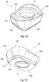
- FIGs. 1A and 1B are perspective views of a cutting insert 10 according to an embodiment of the present invention.
- Figs. 2A, 2B and 2C are a front view of the cutting insert 10, a left side view thereof and a bottom view thereof in relation to the front view, respectively.
- the cutting insert 10 comprises an upper surface 10a, a lower surface 10b and a peripheral side surface which connects the upper surface 10a and the lower surface 10b.
- the peripheral side surface comprises substantially flat side surface parts 10d (a first side surface part) and 10d' (a second side surface part) and front surface parts 10e (a first front surface part) and 10e' (a second front surface part), which each connect the two side surface parts.
- part of a connecting part between the upper surface 10a and the side surface part 10d has a linear shape.
- part of a connecting part between the upper surface 10a and the side surface part 10d' has a linear shape which is parallel to the above linear shape.
- an interval between the parts respectively constituting the above linear shapes is defined as a width W of the cutting insert 10.
- the width W of the cutting insert 10 according to the present embodiment may be, for example, from 4 mm to 4.5 mm.
- the lower surface 10b of the cutting insert 10 is comprised of a flat surface. Further, the cutting insert 10 is provided with, at a center part thereof, a through hole H which penetrates the upper surface 10a and the lower surface 10b. A clamp screw to pass through the through hole H is screwed into a female thread provided in a seating surface of a body of an indexable rotating tool, whereby the cutting insert 10 is fixed to the body. At this time, the cutting insert 10 is fixed to the body such that a part thereof close to the side surface part 10d is near a rotational axis of the body and a part thereof close to the side surface part 10d' is distant from the rotational axis of the body.
- the cutting insert 10 comprises: a perpendicular part 10h which is connected to the lower surface 10b and comprises a peripheral side surface perpendicular to the lower surface 10b; a connecting part 10j which is connected to the perpendicular part 10h and extends such that a cross-sectional area thereof increases as it heads away from the lower surface 10b; and an inclined part 10k which is connected to the connecting part 10j and extends such that a cross-sectional area thereof increases as it heads away from the lower surface 10b.
- a peripheral side surface of the connecting part 10j has a large inclination angle (a first inclination angle) relative to the peripheral side surface of the perpendicular part 10h, and therefore has a high rate of increase of the cross-sectional area.
- a peripheral side surface of the inclined part 10k has a small inclination angle (a second inclination angle) relative to the peripheral side surface of the perpendicular part 10h, and therefore has a low rate of increase of the cross-sectional area.
- the height increases in the order of the perpendicular part 10h, the connecting part 10j, and the inclined part 10k. Further, the sum of the heights of the perpendicular part 10h and the connecting part 10j is greater than the height of the inclined part 10k.
- the cutting insert 10 has a shape tapered from the upper surface 10a to the lower surface 10b and is structured such that: the inclined part 10k is narrowed such that a cross-sectional area thereof decreases gently from the upper surface 10a toward the lower surface 10b; the connecting part 10j is narrowed such that a cross-sectional area thereof decreases significantly toward the lower surface 10b; and the perpendicular part 10h is connected to the lower surface 10b while a cross-sectional area thereof is kept constant.
- Figs. 2B and 2C show different inclination angels of the inclined part 10k, the respective inclination angles of the connecting part 10j and the inclined part 10k each do not need to be constant.
- an average value of the inclination angle of the connecting part 10j and an average value or a representative value of the inclination angle of the inclined part 10k have a magnitude relationship.
- a connecting part between the upper surface 10a and the front surface part 10e is provided with a cutting edge.
- the cutting edge comprises a corner edge 10f and an inner cutting edge 10g.
- the corner edge 10f is provided at a corner part of the cutting insert 10 and is formed so as to have a predetermined curvature when seen from a direction facing the upper surface 10a.
- the curvature of the corner edge 10f is selected in accordance with the specification of a corner R of a subject of machining. For instance, when the specification of the corner R is set to be 2 mm, the cutting insert 10 is used in which the corner edge 10f has a predetermined radius of curvature (for example, a little less than 2 mm), in order for the corner R to be 2 mm in length after the machining, in consideration of a rotational trajectory of the corner edge.
- a predetermined radius of curvature for example, a little less than 2 mm
- the corner edge 10f is formed so as to be large and to have a greater curvature than that involved in a general case.
- the corner edge 10f is formed so as to reach a position corresponding to from 40% or more to 50% or less of the width W in a direction of the width W (a direction connecting the side surface part 10d and the side surface part 10d'), starting from the side surface part 10d', and the radius of curvature of the corner edge 10f constitutes, for example, 50% or less of the width W.
- the inner cutting edge 10g is formed so as to be continuous with the corner edge 10f.
- the inner cutting edge 10g comprises: a connecting part connected to the corner edge 10f; a major inner cutting edge 10g' formed so as to be substantially linear when seen from the direction facing the upper surface 10a; and a connecting part connected to the side surface part 10d.
- a top part S which has the maximum distance from the lower surface 10b to the cutting edge, is included in the corner edge 10f. It is desirable for the corner edge 10f to be provided such that the top part S is located in a region covering 40% or less of the corner edge 10f, and further preferably 20% or less thereof, starting from the side surface part 10d' in the direction of the width W. In the present embodiment, as shown in Fig. 2B , the top part S is located in the region covering 20% or less of the corner edge 10f, starting from the side surface part 10d' in the direction of the width W. Further, as shown in Figs. 2B and 2C , since the top part S is provided on the corner edge 10f, the top part S can be seen in both the bottom view and the left side view.
- the distance between the corner edge 10f and the lower surface 10b decreases gradually as it heads away from the top part S toward a connecting part of the corner edge 10f with respect to the inner cutting edge 10g.
- the distance between the inner cutting edge 10g and the lower surface 10b also continues to decrease gradually. Further, the distance between the inner cutting edge 10g and the lower surface 10b increases significantly in the connecting part of the inner cutting edge 10g with respect to the side surface part 10d.
- the cutting insert 10 has an axisymmetric structure with respect to the rotational axis of the through hole H. Therefore, a connecting part between the front surface part 10e' and the upper surface 10a is provided with the same cutting edge as the cutting edge constituted by the corner edge 10f and the inner cutting edge 10g.
- Fig. 3A is a perspective view of an end mill E (an indexable rotating tool) on which two cutting inserts 10 have been mounted.
- Fig. 3B is a view of the end mill E seen from a direction of a rotational axis AX.
- Fig. 3C is a view of the end mill E seen from a direction perpendicular to the rotational axis AX.
- the end mill E is a small-diameter end mill E having a tool diameter of from 8 mm to 20 mm, and it can be used for the machining of, for example, a mold.
- a cylindrical body B serving as a leading end part of the end mill E, is provided with two seating surfaces F and F' for respectively mounting cutting inserts 10.
- the seating surfaces F and F' are respectively provided with female threads.
- a clamp screw CS which penetrates the through hole H of each of the cutting inserts 10, is screwed into each of the female threads, whereby the lower surfaces 10b of the cutting inserts 10 are pressed toward the seating surfaces F and F', and each of the cutting inserts 10 is fixed to the body B.
- the front surface part 10e faces in the same direction as the rotational axis AX.
- the cutting insert 10 is mounted on the body B such that the side surface part 10d is near the rotational axis A and the side surface part 10d' is distant from the rotational axis AX. Therefore, the corner edge 10f and the inner cutting edge 10g are located in the direction from the top part S, being located on the side surface part 10d' side, to the rotational axis AX.
- Fig. 4A is a cross-sectional view perpendicular to the cutting edge when the cutting insert 10 is mounted on the body B
- Fig. 4B is a similar cross-sectional view in a comparative example.
- the upper surface 10a of the cutting insert 10 comprises a rake surface 10p and a land 10q connected to the rake surface 10p and the front surface part 10e.
- an axial rake angle of the rake surface 10p is positive (such angle refers to an angle formed by two lines of intersection, i.e., a line of intersection of a P p plane (i.e.
- a clearance angle of the front surface part 10e which functions as a flank, is set at 17°, meaning a relatively large angle, and this can suppress flank wear.
- a positive axial rake is kept throughout the corner edge 10f.
- the corner edge 10f is provided such that it has a smaller axial rake as it heads toward the inner cutting edge 10g.
- both a land thereof and a rake surface thereof have negative axial rakes.
- Figs. 5A and 5B show the results of simulation when a bottom surface of a work is machined while the corner R is formed, using the cutting insert 10 according to the present embodiment, and such simulation is seen from a direction facing the front surface part 10e'.
- the cutting insert 10 is mounted on the body B so as to involve a smaller radial rake angle than that involved in the case of Fig. 5B (such angle refers to an angle formed by two lines of intersection, i.e., a line of intersection of a P f plane (i.e.
- a plane defined by a direction of a principal component of force and a tool feed direction) and a reference plane and a line of intersection of the P f plane and a rake surface; and such angle may also be referred to as a radial rake).
- Figs. 5A to 5D show the results of simulation when a work is machined using cutting inserts I and I' according to the comparative example.
- the top part S is located so as to be close to the side surface part 10d' of the cutting insert 10.
- a radial rake which heads away from the top part S toward the inner cutting edge 10g, has a small negative value. Therefore, it is possible to appropriately curl a chip D which grows along with rotation of the end mill E around the rotational axis AX.
- the axial rake is positive in Fig. 4A , the chip D is not hindered from moving in a direction of a base part of the body B (an upward direction relative to the plane of the page), compared with the case of Fig. 4B , where the axial rake is negative, thereby leading to an improvement in control of the chip D.
- the top part S is located near the center of each of the cutting inserts I and I'.
- the work is machined while the radial rake has a large negative value.
- the axial rake is negative, a force acts which presses the chip D in a direction of a machined surface. Therefore, the chip D is not hindered from being discharged, thereby leading to the chip D being likely to move in a radially outward direction.
- the chip D which grows along with the rotation extends in the radially outward direction and, at the end of chipping (around 200°), the chip D is jammed with respect to a wall surface of the work.
- the top part S is located so as to be close to the side surface part 10d' of the cutting insert 10.
- a radial rake which heads away from the top part S toward the inner cutting edge 10g, has a smaller negative value than that involved in each of the cases of Figs. 5C and 5D . Therefore, it is possible to appropriately curl a chip D which grows along with rotation of the end mill E around the rotational axis AX. Further, since the axial rake is positive in Fig. 4A , the chip D is not hindered from moving in the direction of the base part of the body B, compared with the case where the axial rake is negative, thereby leading to an improvement in control of the chip D.
- the cutting insert 10 according to the present embodiment contributes to an improvement in the rigidity of the body B.
- the width W of the cutting insert 10 according to the present embodiment is from 4 mm to 4.5 mm, meaning that such cutting insert 10 is very thin, and thus, the body B on which such cutting insert 10 is mounted also has a narrow width. Therefore, when the body B is reduced in size, the rigidity of the body B is significantly impaired.
- a corner part which connects a seating surface of the insert seat and the wall surface thereof is hollowed out so as to form a recess.
- the inventors of the present application have focused on the point that the hollowing out of a corner part of an insert seat for the purpose of forming a recess has an influence on the rigidity of a body.
- the cutting insert 10 according to the present embodiment is provided with the inclined part 10k and the connecting part 10j, and thus, in such cutting insert 10, the edge of the lower surface 10b is located close to the center of the lower surface 10b compared with a general cutting insert. Therefore, as shown in Fig. 3B , small recesses can be formed at corner parts C and C' of the insert seats of the body B on which the cutting inserts 10 are mounted. Accordingly, the rigidity of the body B can be increased.
- the width W of the cutting insert 10 is from 4 mm to 4.5 mm, meaning a very narrow width, the contact area of the cutting insert 10 with respect to the seating surface F or F' of the insert seat is limited. If the contact area is too small, it does not allow the cutting insert to be mounted on the body B in a stable manner.
- the cutting insert 10 is provided with the perpendicular part 10h, which is continuous with the inclined part 10k and the connecting part 10j, and this can result in the lower surface 10b having a larger area than that involved in the case of a cutting insert 10 not being provided with the perpendicular part 10h. Therefore, it is possible to keep the contact area of the cutting insert 10 with respect to the seating surface F or F' of the insert seat.
- the cutting insert 10 can be supported in a more stable manner than that involved in the case where a peripheral side surface having a large inclination angle is brought into contact with the wall surface of the insert seat.
- the cutting insert 10 according to the present embodiment can achieve both an increase in the rigidity of the body B and the stable mounting of the cutting insert 10.
- the chip D Since a positive axial rake can be achieved when mounting the cutting insert 10 on the body B, the chip D is not hindered from extending in the direction of the base part of the body B. This leads to an improvement in control of the chip D.
- the axial rake of the corner edge 10f is made gradually smaller while being kept positive, as it heads toward the inner cutting edge 10g. This can suppress damage to the corner edge 10f.
- a cutting insert may be configured so as not to be provided with the land 10q, depending on the subject of machining, and examples of such cutting insert include a cutting insert for aluminum machining.
- top part S is positioned at the end of the cutting edge which is furthest from the rotational axis AX, a negative radial rake can be achieved whose absolute value is smaller than that involved in any case other than that described above.
- Ramping can be performed due to the provision of the inner cutting edge 10g.
- the cutting insert 10 indicated in the present embodiment is intended for the end mill E; however, such cutting insert 10 is also applicable to a wide variety of cutting inserts including a cutting insert for milling.
- 10 Cutting insert; 10a: Upper surface; 10b: Lower surface; 10d: Side surface part; 10e: Front surface part; 10f: Corner edge; 10g: Inner cutting edge; 10h: Perpendicular part; 10j: Connecting part; 10k: Inclined part; 10p: Rake surface; 10q: Land; AX: Rotational axis; B: Body; C: Corner part; E: End mill; F: Seating surface; H: Through hole; S: Top part; W: Width
Landscapes
- Engineering & Computer Science (AREA)
- Mechanical Engineering (AREA)
- Milling Processes (AREA)
Abstract
Description
- The present invention relates to a cutting insert and an indexable rotating tool.
- During the machining of a mold, etc., a thin end mill with a tool diameter of approximately from 8 mm to 20 mm has conventionally been used. In order to round a corner of a casting, a curved surface (referred to as a "corner R" or the like) needs to be formed between a bottom surface of the mold and a wall surface thereof.
- Patent Document 1 discloses an insert 1 which comprises corner parts 11 each having a high curvature radius in order for such corner R to be formed.
- Patent Document 1:
JP2009-119572 A - However, a conventional cutting insert has low efficiency in discharging the chips produced and has therefore involved the jamming of chips during cutting.
- In view of the above, an object of the present invention is to provide a cutting insert and an indexable rotating tool which achieve an improvement of chip discharging efficiency.
- A cutting insert according to an aspect of the present disclosure is mounted on an indexable rotating tool comprising a body that rotates about a predetermined rotational axis. Further, the above cutting insert comprises: an upper surface; a lower surface to be mounted on a seating surface of the body; and a peripheral side surface which connects the upper surface and the lower surface and regarding which a cutting edge is formed with respect to the upper surface.
- The cutting edge comprises: an inner cutting edge; and a corner cutting edge which is connected to the inner cutting edge and which, in a plan view seen from a direction facing the upper surface, has a predetermined curvature, has a width corresponding to from 40% or more to 50% or less of a width of the cutting insert in a direction perpendicular to the rotational axis, and is formed at a position that is further from the rotational axis than the inner cutting edge, and, as to a distance between the lower surface and the cutting edge, a top part, which has a maximum distance from the lower surface, is located on the corner cutting edge, and in the plan view seen from the direction facing the upper surface, the top part is formed in a region covering 20% or less of the width of the cutting insert, starting from an end that is furthest from the rotational axis of the cutting insert in the direction perpendicular to the rotational axis.
- A cutting insert according to another aspect of the present disclosure is mounted on an indexable rotating tool comprising a body that rotates about a predetermined rotational axis. The above cutting insert comprises: an upper surface; a lower surface to be mounted on a seating surface of a body; and a peripheral side surface which connects the upper surface and the lower surface and regarding which a cutting edge is formed with respect to the upper surface. Further, the cutting edge comprises: an inner cutting edge; and a corner cutting edge which is connected to the inner cutting edge and which, in a plan view seen from a direction facing the upper surface, has a predetermined curvature, and is formed at a position that is further from the rotational axis than the inner cutting edge.
- The cutting insert further comprises: a perpendicular part which is connected to the lower surface and which comprises, as the peripheral side surface, a perpendicular surface to the lower surface; a connecting part which is connected to the perpendicular part and which comprises, as the peripheral side surface, a surface that forms a first inclination angle with the perpendicular surface; and an inclined part which is connected to the connecting part and which comprises, as the peripheral side surface, a surface that forms a second inclination angle, being smaller than the first inclination angle, with the perpendicular surface.
- An indexable rotating tool according to a further aspect of the present disclosure comprises: a body which rotates about a predetermined rotational axis and has a diameter of 15 mm or less; and a cutting insert which is mounted on each of at least two seating surfaces formed in the body.
-
-
Figs. 1A and 1B are perspective views of acutting insert 10. -
Figs. 2A, 2B and 2C are a front view of thecutting insert 10, a left side view thereof and a bottom view thereof, respectively. -
Figs. 3A, 3B and 3C illustrate an end mill E on which twocutting inserts 10 have been mounted. -
Figs. 4A and 4B are cross-sectional views perpendicular to a cutting edge when thecutting insert 10 is mounted on a body B. -
Figs. 5A to 5D show simulation results of machining with the use of thecutting insert 10. - Embodiments of the present invention will hereinafter be described with reference to the drawings. The embodiments below are illustrative in order to describe the present invention and are not intended to limit the present invention to such embodiments.
-
Figs. 1A and 1B are perspective views of a cutting insert 10 according to an embodiment of the present invention.Figs. 2A, 2B and 2C are a front view of thecutting insert 10, a left side view thereof and a bottom view thereof in relation to the front view, respectively. - As shown in the above figures, the
cutting insert 10 comprises anupper surface 10a, alower surface 10b and a peripheral side surface which connects theupper surface 10a and thelower surface 10b. The peripheral side surface comprises substantially flatside surface parts 10d (a first side surface part) and 10d' (a second side surface part) andfront surface parts 10e (a first front surface part) and 10e' (a second front surface part), which each connect the two side surface parts. - As shown in
Fig. 2A , part of a connecting part between theupper surface 10a and theside surface part 10d has a linear shape. Similarly, part of a connecting part between theupper surface 10a and theside surface part 10d' has a linear shape which is parallel to the above linear shape. As shown inFigs. 2A and 2B , an interval between the parts respectively constituting the above linear shapes is defined as a width W of thecutting insert 10. The width W of the cutting insert 10 according to the present embodiment may be, for example, from 4 mm to 4.5 mm. - The
lower surface 10b of thecutting insert 10 is comprised of a flat surface. Further, thecutting insert 10 is provided with, at a center part thereof, a through hole H which penetrates theupper surface 10a and thelower surface 10b. A clamp screw to pass through the through hole H is screwed into a female thread provided in a seating surface of a body of an indexable rotating tool, whereby thecutting insert 10 is fixed to the body. At this time, thecutting insert 10 is fixed to the body such that a part thereof close to theside surface part 10d is near a rotational axis of the body and a part thereof close to theside surface part 10d' is distant from the rotational axis of the body. - As shown in
Figs. 2B and 2C , thecutting insert 10 comprises: aperpendicular part 10h which is connected to thelower surface 10b and comprises a peripheral side surface perpendicular to thelower surface 10b; a connectingpart 10j which is connected to theperpendicular part 10h and extends such that a cross-sectional area thereof increases as it heads away from thelower surface 10b; and aninclined part 10k which is connected to the connectingpart 10j and extends such that a cross-sectional area thereof increases as it heads away from thelower surface 10b. As shown in the figures, a peripheral side surface of the connectingpart 10j has a large inclination angle (a first inclination angle) relative to the peripheral side surface of theperpendicular part 10h, and therefore has a high rate of increase of the cross-sectional area. Meanwhile, a peripheral side surface of theinclined part 10k has a small inclination angle (a second inclination angle) relative to the peripheral side surface of theperpendicular part 10h, and therefore has a low rate of increase of the cross-sectional area. - In terms of the height in a direction perpendicular to the
lower surface 10b, the height increases in the order of theperpendicular part 10h, the connectingpart 10j, and theinclined part 10k. Further, the sum of the heights of theperpendicular part 10h and the connectingpart 10j is greater than the height of theinclined part 10k. - In other words, the
cutting insert 10 has a shape tapered from theupper surface 10a to thelower surface 10b and is structured such that: theinclined part 10k is narrowed such that a cross-sectional area thereof decreases gently from theupper surface 10a toward thelower surface 10b; the connectingpart 10j is narrowed such that a cross-sectional area thereof decreases significantly toward thelower surface 10b; and theperpendicular part 10h is connected to thelower surface 10b while a cross-sectional area thereof is kept constant. It should be noted that, asFigs. 2B and 2C show different inclination angels of theinclined part 10k, the respective inclination angles of the connectingpart 10j and theinclined part 10k each do not need to be constant. However, an average value of the inclination angle of the connectingpart 10j and an average value or a representative value of the inclination angle of theinclined part 10k have a magnitude relationship. - A connecting part between the
upper surface 10a and thefront surface part 10e is provided with a cutting edge. The cutting edge comprises acorner edge 10f and an innercutting edge 10g. - The
corner edge 10f is provided at a corner part of thecutting insert 10 and is formed so as to have a predetermined curvature when seen from a direction facing theupper surface 10a. The curvature of thecorner edge 10f is selected in accordance with the specification of a corner R of a subject of machining. For instance, when the specification of the corner R is set to be 2 mm, the cuttinginsert 10 is used in which thecorner edge 10f has a predetermined radius of curvature (for example, a little less than 2 mm), in order for the corner R to be 2 mm in length after the machining, in consideration of a rotational trajectory of the corner edge. In the present embodiment, as shown inFig. 2A , thecorner edge 10f is formed so as to be large and to have a greater curvature than that involved in a general case. When seen from the direction facing theupper surface 10a, thecorner edge 10f is formed so as to reach a position corresponding to from 40% or more to 50% or less of the width W in a direction of the width W (a direction connecting theside surface part 10d and theside surface part 10d'), starting from theside surface part 10d', and the radius of curvature of thecorner edge 10f constitutes, for example, 50% or less of the width W. - Further, as shown in, for example,
Figs. 2A and 2B , theinner cutting edge 10g is formed so as to be continuous with thecorner edge 10f. Theinner cutting edge 10g comprises: a connecting part connected to thecorner edge 10f; a majorinner cutting edge 10g' formed so as to be substantially linear when seen from the direction facing theupper surface 10a; and a connecting part connected to theside surface part 10d. - As shown in
Figs. 2B and 2C , a top part S, which has the maximum distance from thelower surface 10b to the cutting edge, is included in thecorner edge 10f. It is desirable for thecorner edge 10f to be provided such that the top part S is located in a region covering 40% or less of thecorner edge 10f, and further preferably 20% or less thereof, starting from theside surface part 10d' in the direction of the width W. In the present embodiment, as shown inFig. 2B , the top part S is located in the region covering 20% or less of thecorner edge 10f, starting from theside surface part 10d' in the direction of the width W. Further, as shown inFigs. 2B and 2C , since the top part S is provided on thecorner edge 10f, the top part S can be seen in both the bottom view and the left side view. - As shown in
Fig. 2B , the distance between thecorner edge 10f and thelower surface 10b decreases gradually as it heads away from the top part S toward a connecting part of thecorner edge 10f with respect to theinner cutting edge 10g. The distance between theinner cutting edge 10g and thelower surface 10b also continues to decrease gradually. Further, the distance between theinner cutting edge 10g and thelower surface 10b increases significantly in the connecting part of theinner cutting edge 10g with respect to theside surface part 10d. - The cutting
insert 10 has an axisymmetric structure with respect to the rotational axis of the through hole H. Therefore, a connecting part between thefront surface part 10e' and theupper surface 10a is provided with the same cutting edge as the cutting edge constituted by thecorner edge 10f and theinner cutting edge 10g. -
Fig. 3A is a perspective view of an end mill E (an indexable rotating tool) on which two cutting inserts 10 have been mounted.Fig. 3B is a view of the end mill E seen from a direction of a rotational axis AX.Fig. 3C is a view of the end mill E seen from a direction perpendicular to the rotational axis AX. The end mill E is a small-diameter end mill E having a tool diameter of from 8 mm to 20 mm, and it can be used for the machining of, for example, a mold. - As shown in the above figures, a cylindrical body B, serving as a leading end part of the end mill E, is provided with two seating surfaces F and F' for respectively mounting cutting inserts 10. The seating surfaces F and F' are respectively provided with female threads. A clamp screw CS, which penetrates the through hole H of each of the cutting inserts 10, is screwed into each of the female threads, whereby the
lower surfaces 10b of the cutting inserts 10 are pressed toward the seating surfaces F and F', and each of the cutting inserts 10 is fixed to the body B. At this time, thefront surface part 10e faces in the same direction as the rotational axis AX. Further, the cuttinginsert 10 is mounted on the body B such that theside surface part 10d is near the rotational axis A and theside surface part 10d' is distant from the rotational axis AX. Therefore, thecorner edge 10f and theinner cutting edge 10g are located in the direction from the top part S, being located on theside surface part 10d' side, to the rotational axis AX. -
Fig. 4A is a cross-sectional view perpendicular to the cutting edge when the cuttinginsert 10 is mounted on the body B, andFig. 4B is a similar cross-sectional view in a comparative example. - As shown in
Fig. 4A , theupper surface 10a of the cuttinginsert 10 comprises arake surface 10p and aland 10q connected to therake surface 10p and thefront surface part 10e. As shown in the above figure, an axial rake angle of therake surface 10p is positive (such angle refers to an angle formed by two lines of intersection, i.e., a line of intersection of a Pp plane (i.e. a plane defined by a direction of a principal component of force and a depth-of-cut direction) and a reference plane and a line of intersection of the Pp plane and a rake surface; and such angle may also be referred to as an axial rake); namely, therake surface 10p is inclined backward so as to extend backward in a rotating direction as it heads away from thecorner edge 10f (and theinner cutting edge 10g). Meanwhile, an axial rake of theland 10q is negative; namely, theland 10q is inclined forward in the rotating direction as it heads away from thecorner edge 10f (and theinner cutting edge 10g). It should be noted that a clearance angle of thefront surface part 10e, which functions as a flank, is set at 17°, meaning a relatively large angle, and this can suppress flank wear. A positive axial rake is kept throughout thecorner edge 10f. However, thecorner edge 10f is provided such that it has a smaller axial rake as it heads toward theinner cutting edge 10g. - As shown in
Fig. 4B , in the case of a cutting insert I in a comparative example, both a land thereof and a rake surface thereof have negative axial rakes. -
Figs. 5A and 5B show the results of simulation when a bottom surface of a work is machined while the corner R is formed, using the cuttinginsert 10 according to the present embodiment, and such simulation is seen from a direction facing thefront surface part 10e'. However, in the case ofFig. 5A , the cuttinginsert 10 is mounted on the body B so as to involve a smaller radial rake angle than that involved in the case ofFig. 5B (such angle refers to an angle formed by two lines of intersection, i.e., a line of intersection of a Pf plane (i.e. a plane defined by a direction of a principal component of force and a tool feed direction) and a reference plane and a line of intersection of the Pf plane and a rake surface; and such angle may also be referred to as a radial rake). -
Figs. 5A to 5D show the results of simulation when a work is machined using cutting inserts I and I' according to the comparative example. - In the case of
Fig. 5A , the top part S is located so as to be close to theside surface part 10d' of the cuttinginsert 10. Thus, the work can be machined while a radial rake, which heads away from the top part S toward theinner cutting edge 10g, has a small negative value. Therefore, it is possible to appropriately curl a chip D which grows along with rotation of the end mill E around the rotational axis AX. Further, since the axial rake is positive inFig. 4A , the chip D is not hindered from moving in a direction of a base part of the body B (an upward direction relative to the plane of the page), compared with the case ofFig. 4B , where the axial rake is negative, thereby leading to an improvement in control of the chip D. - Meanwhile, in the cases of
Figs. 5C and 5D , the top part S is located near the center of each of the cutting inserts I and I'. Thus, the work is machined while the radial rake has a large negative value. Further, since the axial rake is negative, a force acts which presses the chip D in a direction of a machined surface. Therefore, the chip D is not hindered from being discharged, thereby leading to the chip D being likely to move in a radially outward direction. - The above may result in the case where the chip D which grows along with the rotation extends in the radially outward direction and, at the end of chipping (around 200°), the chip D is jammed with respect to a wall surface of the work.
- In the case of
Fig. 5B as well, the top part S is located so as to be close to theside surface part 10d' of the cuttinginsert 10. Thus, the work can be machined while a radial rake, which heads away from the top part S toward theinner cutting edge 10g, has a smaller negative value than that involved in each of the cases ofFigs. 5C and 5D . Therefore, it is possible to appropriately curl a chip D which grows along with rotation of the end mill E around the rotational axis AX. Further, since the axial rake is positive inFig. 4A , the chip D is not hindered from moving in the direction of the base part of the body B, compared with the case where the axial rake is negative, thereby leading to an improvement in control of the chip D. - The cutting
insert 10 according to the present embodiment contributes to an improvement in the rigidity of the body B. The width W of the cuttinginsert 10 according to the present embodiment is from 4 mm to 4.5 mm, meaning thatsuch cutting insert 10 is very thin, and thus, the body B on whichsuch cutting insert 10 is mounted also has a narrow width. Therefore, when the body B is reduced in size, the rigidity of the body B is significantly impaired. - Meanwhile, when mounting a cutting insert on a body, in order to reliably bring a side surface of the cutting insert into contact with a wall surface of an insert seat of the body, a corner part which connects a seating surface of the insert seat and the wall surface thereof is hollowed out so as to form a recess.
- The inventors of the present application have focused on the point that the hollowing out of a corner part of an insert seat for the purpose of forming a recess has an influence on the rigidity of a body.
- The cutting
insert 10 according to the present embodiment is provided with theinclined part 10k and the connectingpart 10j, and thus, insuch cutting insert 10, the edge of thelower surface 10b is located close to the center of thelower surface 10b compared with a general cutting insert. Therefore, as shown inFig. 3B , small recesses can be formed at corner parts C and C' of the insert seats of the body B on which the cutting inserts 10 are mounted. Accordingly, the rigidity of the body B can be increased. - Further, since the width W of the cutting
insert 10 is from 4 mm to 4.5 mm, meaning a very narrow width, the contact area of the cuttinginsert 10 with respect to the seating surface F or F' of the insert seat is limited. If the contact area is too small, it does not allow the cutting insert to be mounted on the body B in a stable manner. - The cutting
insert 10 is provided with theperpendicular part 10h, which is continuous with theinclined part 10k and the connectingpart 10j, and this can result in thelower surface 10b having a larger area than that involved in the case of a cuttinginsert 10 not being provided with theperpendicular part 10h. Therefore, it is possible to keep the contact area of the cuttinginsert 10 with respect to the seating surface F or F' of the insert seat. - Further, since the peripheral side surface of the
inclined part 10k, which has a relatively small inclination angle, can be brought into contact with the wall surface of the insert seat, the cuttinginsert 10 can be supported in a more stable manner than that involved in the case where a peripheral side surface having a large inclination angle is brought into contact with the wall surface of the insert seat. - Accordingly, the cutting
insert 10 according to the present embodiment can achieve both an increase in the rigidity of the body B and the stable mounting of the cuttinginsert 10. - Since a positive axial rake can be achieved when mounting the cutting
insert 10 on the body B, the chip D is not hindered from extending in the direction of the base part of the body B. This leads to an improvement in control of the chip D. - There have been cases in which a large axial rake may lead to damage to the cutting edge. Therefore, the axial rake of the
corner edge 10f is made gradually smaller while being kept positive, as it heads toward theinner cutting edge 10g. This can suppress damage to thecorner edge 10f. - The strength of the cutting edge can be improved due to the provision of the
land 10q. However, a cutting insert may be configured so as not to be provided with theland 10q, depending on the subject of machining, and examples of such cutting insert include a cutting insert for aluminum machining. - Since the top part S is positioned at the end of the cutting edge which is furthest from the rotational axis AX, a negative radial rake can be achieved whose absolute value is smaller than that involved in any case other than that described above.
- Ramping can be performed due to the provision of the
inner cutting edge 10g. - The cutting
insert 10 indicated in the present embodiment is intended for the end mill E; however,such cutting insert 10 is also applicable to a wide variety of cutting inserts including a cutting insert for milling. - Various modifications may be made to the present invention without departing from the gist of the invention. For example, some components in an embodiment may be incorporated into another embodiment within the extent of the ordinary creativity of a person skilled in the art.
- 10: Cutting insert; 10a: Upper surface; 10b: Lower surface; 10d: Side surface part; 10e: Front surface part; 10f: Corner edge; 10g: Inner cutting edge; 10h: Perpendicular part; 10j: Connecting part; 10k: Inclined part; 10p: Rake surface; 10q: Land; AX: Rotational axis; B: Body; C: Corner part; E: End mill; F: Seating surface; H: Through hole; S: Top part; W: Width
Claims (10)
- A cutting insert which is mounted on an indexable rotating tool comprising a body that rotates about a predetermined rotational axis, the cutting insert comprising:an upper surface; a lower surface to be mounted on a seating surface of the body; and a peripheral side surface which connects the upper surface and the lower surface and regarding which a cutting edge is formed with respect to the upper surface,wherein the cutting edge comprises:an inner cutting edge; anda corner cutting edge which is connected to the inner cutting edge and which, in a plan view seen from a direction facing the upper surface, has a predetermined curvature, has a width corresponding to from 40% or more to 50% or less of a width of the cutting insert in a direction perpendicular to the rotational axis, and is formed at a position that is further from the rotational axis than the inner cutting edge, andwherein, as to a distance between the lower surface and the cutting edge, a top part, which has a maximum distance from the lower surface, is located on the corner cutting edge, and in the plan view seen from the direction facing the upper surface, the top part is formed in a region covering 20% or less of the width of the cutting insert, starting from an end that is furthest from the rotational axis of the cutting insert in the direction perpendicular to the rotational axis.
- The cutting insert according to claim 1, wherein the width of the cutting insert is 5 mm or less.
- The cutting insert according to claim 1, wherein the cutting insert comprises:a perpendicular part which is connected to the lower surface and which comprises, as the peripheral side surface, a perpendicular surface to the lower surface;a connecting part which is connected to the perpendicular part and which comprises, as the peripheral side surface, a surface that forms a first inclination angle with the perpendicular surface; andan inclined part which is connected to the connecting part and which comprises, as the peripheral side surface, a surface that forms a second inclination angle, being smaller than the first inclination angle, with the perpendicular surface.
- The cutting insert according to claim 1, wherein the corner cutting edge is provided such that a distance thereof from the lower surface decreases gradually as it heads away from the top part toward a connecting part of the corner cutting edge with respect to the inner cutting edge.
- The cutting insert according to claim 4, wherein the inner cutting edge comprises a portion whose distance from the lower surface is gradually reduced from a connecting part of the inner cutting edge with respect to the corner cutting edge.
- The cutting insert according to claim 1, wherein:the cutting insert is provided with a through hole for allowing a screw for mounting the cutting insert on the body to pass through the through hole so as to communicate with the upper surface and the lower surface; anda second cutting edge, being the same as the cutting edge, is provided so as to be in symmetry about a rotational axis of the through hole.
- A cutting insert which is mounted on an indexable rotating tool comprising a body that rotates about a predetermined rotational axis, the cutting insert comprising:an upper surface; a lower surface to be mounted on a seating surface of the body; and a peripheral side surface which connects the upper surface and the lower surface and regarding which a cutting edge is formed with respect to the upper surface,wherein the cutting edge comprises:an inner cutting edge; anda corner cutting edge which is connected to the inner cutting edge and which, in a plan view seen from a direction facing the upper surface, has a predetermined curvature, has a width corresponding to from 40% or more to 50% or less of a width of the cutting insert in a direction perpendicular to the rotational axis, and is formed at a position that is further from the rotational axis than the inner cutting edge,wherein the width of the cutting insert is from 4 mm or more to 4.5 mm or less, wherein, as to a distance between the lower surface and the cutting edge, a top part, which has a maximum distance from the lower surface, is located on the corner cutting edge, and in the plan view seen from the direction facing the upper surface, the top part is formed in a region covering 20% or less of the width of the cutting insert, starting from an end of the cutting insert in the direction perpendicular to the rotational axis, andwherein the cutting insert comprises:a perpendicular part which is connected to the lower surface and which comprises, as the peripheral side surface, a perpendicular surface to the lower surface;a first inclined part which is connected to the perpendicular part and which comprises, as the peripheral side surface, a surface that forms a first inclination angle with the perpendicular surface; anda second inclined part which is connected to the first inclined part and which comprises, as the peripheral side surface, a surface that forms a second inclination angle, being smaller than the first inclination angle, with the perpendicular surface.
- An indexable rotating tool comprising:a body which rotates about a predetermined rotational axis and has a diameter of 15 mm or less; andthe cutting insert according to claim 1 which is mounted on each of at least two seating surfaces formed in the body.
- The indexable rotating tool according to claim 8, wherein the upper surface of the cutting insert comprises:a rake surface which has a positive axial rake; anda land which connects the rake surface and the corner cutting edge and has a negative axial rake.
- The indexable rotating tool according to claim 9, wherein a positive axial rake of the rake surface of the cutting insert becomes smaller as it heads away from the top part toward a connecting part of the corner cutting edge with respect to the inner cutting edge.
Applications Claiming Priority (1)
| Application Number | Priority Date | Filing Date | Title |
|---|---|---|---|
| JP2017205726A JP6508620B1 (en) | 2017-10-25 | 2017-10-25 | Cutting insert and cutting edge exchange type cutting tool |
Publications (2)
| Publication Number | Publication Date |
|---|---|
| EP3476512A1 true EP3476512A1 (en) | 2019-05-01 |
| EP3476512B1 EP3476512B1 (en) | 2026-03-04 |
Family
ID=63914950
Family Applications (1)
| Application Number | Title | Priority Date | Filing Date |
|---|---|---|---|
| EP18201374.8A Active EP3476512B1 (en) | 2017-10-25 | 2018-10-19 | Indexable cutting insert and rotating tool |
Country Status (4)
| Country | Link |
|---|---|
| US (1) | US10625352B2 (en) |
| EP (1) | EP3476512B1 (en) |
| JP (1) | JP6508620B1 (en) |
| CN (1) | CN109702259B (en) |
Cited By (1)
| Publication number | Priority date | Publication date | Assignee | Title |
|---|---|---|---|---|
| EP3950197A4 (en) * | 2019-03-27 | 2022-05-25 | Sumitomo Electric Hardmetal Corp. | CUTTER BODY, CUTTER INSERT AND CUTTER |
Families Citing this family (3)
| Publication number | Priority date | Publication date | Assignee | Title |
|---|---|---|---|---|
| US11344958B2 (en) * | 2019-04-18 | 2022-05-31 | Tungaloy Corporation | Cutting insert |
| CN113695652B (en) * | 2021-07-27 | 2022-09-20 | 厦门金鹭特种合金有限公司 | Indexable cutting insert and indexable cutting tool thereof |
| USD1064007S1 (en) * | 2022-08-16 | 2025-02-25 | Taegutec Ltd. | Cutting insert |
Citations (5)
| Publication number | Priority date | Publication date | Assignee | Title |
|---|---|---|---|---|
| EP0585800A1 (en) * | 1992-09-01 | 1994-03-09 | Iscar Ltd. | A cutting insert for a milling cutter tool |
| WO2006041353A1 (en) * | 2004-09-06 | 2006-04-20 | Sandvik Intellectual Property Ab | A milling tool, a cutting insert for milling tool as well as a solid milling tool |
| JP2009119572A (en) | 2007-11-16 | 2009-06-04 | Hitachi Tool Engineering Ltd | Insert and edge replaceable cutting tool |
| WO2014196573A1 (en) * | 2013-06-05 | 2014-12-11 | 株式会社タンガロイ | Cutting insert and tip replacement-type cutting tool |
| US20150139743A1 (en) * | 2013-11-21 | 2015-05-21 | Iscar, Ltd. | Single-sided indexable ramping milling insert and ramping milling tool |
Family Cites Families (31)
| Publication number | Priority date | Publication date | Assignee | Title |
|---|---|---|---|---|
| DE4315251C5 (en) * | 1992-05-07 | 2008-12-18 | Mitsubishi Materials Corp. | cutting insert |
| US5388932A (en) * | 1993-09-13 | 1995-02-14 | Kennametal Inc. | Cutting insert for a milling cutter |
| IL110785A (en) * | 1994-08-25 | 1998-04-05 | Iscar Ltd | Cutting insert for a rotary milling cutter |
| CN1154670A (en) * | 1995-03-24 | 1997-07-16 | 伊斯卡有限公司 | Insert blade |
| US5692860A (en) * | 1995-06-06 | 1997-12-02 | Ingersoll Cutting Tool | On-edge end milling cutter and insert |
| US5775855A (en) * | 1995-06-08 | 1998-07-07 | Valenite Inc. | Cutting insert and cutter for milling |
| JPH09108989A (en) * | 1995-10-11 | 1997-04-28 | Hitachi Tool Eng Ltd | Cutting method using low temperature coolant |
| US5893683A (en) * | 1997-04-29 | 1999-04-13 | Ingersoll Cutting Tool Company | Indexable insert router |
| JP3744692B2 (en) * | 1998-07-30 | 2006-02-15 | 京セラ株式会社 | Throw-away end mill |
| US6186705B1 (en) * | 1999-02-23 | 2001-02-13 | Ingersoll Cutting Tool Company | Cutting insert with chip control |
| US6050752A (en) * | 1999-03-19 | 2000-04-18 | Kennametal Inc. | Cutting insert |
| SE520997C2 (en) * | 2001-01-09 | 2003-09-23 | Sandvik Ab | Reversible cutter with grooved coupling surface against the holder and central material portion for fasteners |
| JP2002210609A (en) * | 2001-01-18 | 2002-07-30 | Kanazawa Inst Of Technology | Cutting tools |
| AT5969U1 (en) * | 2001-12-21 | 2003-02-25 | Plansee Tizit Ag | MILLING TOOL |
| US7070363B2 (en) * | 2004-07-15 | 2006-07-04 | Kennametal Inc. | Cutting insert for high-speed milling cutter |
| SE528710C2 (en) * | 2005-06-01 | 2007-01-30 | Sandvik Intellectual Property | Indexable cutter with the coupling means arranged on a release surface |
| AT8743U1 (en) * | 2005-10-19 | 2006-12-15 | Ceratizit Austria Gmbh | MILLING TOOL |
| SE529979C2 (en) * | 2006-01-30 | 2008-01-22 | Sandvik Intellectual Property | Drill bit and drill bit where the orifice surface of the insert hole has a cross-sectional convex shape |
| JPWO2009034633A1 (en) | 2007-09-13 | 2010-12-16 | 株式会社タンガロイ | Throw-away tip for radius cutter, and throw-away type radius cutter equipped with the tip |
| SE532649C2 (en) * | 2008-07-07 | 2010-03-09 | Sandvik Intellectual Property | Indexable cutter |
| IL193284A (en) * | 2008-08-06 | 2014-06-30 | Iscar Ltd | Milling tools and cutting tool for it |
| CA2757400A1 (en) * | 2009-04-02 | 2010-10-07 | Tungaloy Corporation | Cutting insert and cutting edge replaceable cutting tool |
| CN102802855B (en) * | 2009-06-29 | 2015-07-15 | 京瓷株式会社 | Cutting insert, cutting tool, and method of manufacturing a cut product using the cutting tool |
| US8858126B2 (en) * | 2009-09-25 | 2014-10-14 | Kennametal Inc. | Cutting tool with error proofing feature |
| US9033621B2 (en) | 2011-09-19 | 2015-05-19 | Iscar, Ltd. | Cutting insert, cutting body and clamping mechanism of a cutting tool assembly for chip removal |
| CN103857486B (en) * | 2012-10-10 | 2016-04-27 | 伊斯卡有限公司 | Cutting tool, cutting body and clamping mechanism of cutting tool assembly for cutting removal |
| EP3100811B1 (en) * | 2014-01-28 | 2022-09-21 | MOLDINO Tool Engineering, Ltd. | Insert and indexable rotary cutting tool |
| CN107000082B (en) * | 2015-03-05 | 2020-03-13 | 株式会社泰珂洛 | Cutting insert and cutting edge replaceable rotary cutting tool |
| US9993884B2 (en) * | 2015-07-16 | 2018-06-12 | Kennametal Inc. | Double-sided tangential cutting insert |
| JP5967330B1 (en) * | 2015-09-25 | 2016-08-10 | 三菱日立ツール株式会社 | Cutting insert and cutting edge exchangeable rotary cutting tool |
| EP3455018B1 (en) * | 2016-05-13 | 2020-06-24 | Seco Tools Ab | Indexable single-sided cutting insert with means for preventing improper mounting of the insert, and cutting tool including such an insert |
-
2017
- 2017-10-25 JP JP2017205726A patent/JP6508620B1/en active Active
-
2018
- 2018-09-17 US US16/132,589 patent/US10625352B2/en active Active
- 2018-09-18 CN CN201811086150.3A patent/CN109702259B/en active Active
- 2018-10-19 EP EP18201374.8A patent/EP3476512B1/en active Active
Patent Citations (5)
| Publication number | Priority date | Publication date | Assignee | Title |
|---|---|---|---|---|
| EP0585800A1 (en) * | 1992-09-01 | 1994-03-09 | Iscar Ltd. | A cutting insert for a milling cutter tool |
| WO2006041353A1 (en) * | 2004-09-06 | 2006-04-20 | Sandvik Intellectual Property Ab | A milling tool, a cutting insert for milling tool as well as a solid milling tool |
| JP2009119572A (en) | 2007-11-16 | 2009-06-04 | Hitachi Tool Engineering Ltd | Insert and edge replaceable cutting tool |
| WO2014196573A1 (en) * | 2013-06-05 | 2014-12-11 | 株式会社タンガロイ | Cutting insert and tip replacement-type cutting tool |
| US20150139743A1 (en) * | 2013-11-21 | 2015-05-21 | Iscar, Ltd. | Single-sided indexable ramping milling insert and ramping milling tool |
Cited By (2)
| Publication number | Priority date | Publication date | Assignee | Title |
|---|---|---|---|---|
| EP3950197A4 (en) * | 2019-03-27 | 2022-05-25 | Sumitomo Electric Hardmetal Corp. | CUTTER BODY, CUTTER INSERT AND CUTTER |
| US12280439B2 (en) | 2019-03-27 | 2025-04-22 | Sumitomo Electric Hardmetal Corp. | Cutting tool body, cutting insert, and cutting tool |
Also Published As
| Publication number | Publication date |
|---|---|
| EP3476512B1 (en) | 2026-03-04 |
| CN109702259A (en) | 2019-05-03 |
| US10625352B2 (en) | 2020-04-21 |
| JP2019076996A (en) | 2019-05-23 |
| US20190118275A1 (en) | 2019-04-25 |
| JP6508620B1 (en) | 2019-05-08 |
| CN109702259B (en) | 2020-10-20 |
Similar Documents
| Publication | Publication Date | Title |
|---|---|---|
| EP3476512B1 (en) | Indexable cutting insert and rotating tool | |
| EP3199284B1 (en) | An indexable cutting insert for an end mill tool and an end mill tool provided with such an insert | |
| JP6531883B1 (en) | Cutting insert and indexable cutting tool | |
| KR102624246B1 (en) | Turning inserts and methods | |
| KR20180063116A (en) | Turning insert | |
| JP7049263B2 (en) | Face grooving tool for metal cutting | |
| JP7158387B2 (en) | Cutting inserts and shoulder milling tools | |
| KR20180063118A (en) | Method for machining metal workpieces by turning | |
| KR20090055625A (en) | Cutting insert with elliptical cutting edge | |
| EP2832482B1 (en) | Replaceable head cutting tool | |
| EP3266547A1 (en) | Cutting insert and cutting edge-replaceable rotary cutting tool | |
| JP6540928B1 (en) | End insert of cutting insert, indexable ball end mill, and indexable ball end mill | |
| EP3338931A1 (en) | Cutting insert and cutting tool | |
| CN111822765B (en) | Cutting insert | |
| US10596635B2 (en) | Cutting insert for back turning | |
| JP2013500166A (en) | Cutting inserts for cutting tools, especially for high speed milling | |
| US11052465B2 (en) | Turning insert | |
| JP7101679B2 (en) | Cutting inserts and shoulder milling tools | |
| CN101384389B (en) | knives | |
| US11654495B2 (en) | Cutting insert for a shoulder milling tool | |
| JP2014083667A (en) | Cutting insert and tip replaceable cutting tool | |
| EP4108365A1 (en) | Cutting insert | |
| JP7417137B2 (en) | Cutting inserts and indexable ball end mills | |
| EP4052823A1 (en) | Metal cutting milling tool | |
| EP3098007A1 (en) | A milling cutting tool and a cutting insert for a milling cutting tool |
Legal Events
| Date | Code | Title | Description |
|---|---|---|---|
| PUAI | Public reference made under article 153(3) epc to a published international application that has entered the european phase |
Free format text: ORIGINAL CODE: 0009012 |
|
| STAA | Information on the status of an ep patent application or granted ep patent |
Free format text: STATUS: REQUEST FOR EXAMINATION WAS MADE |
|
| 17P | Request for examination filed |
Effective date: 20181102 |
|
| AK | Designated contracting states |
Kind code of ref document: A1 Designated state(s): AL AT BE BG CH CY CZ DE DK EE ES FI FR GB GR HR HU IE IS IT LI LT LU LV MC MK MT NL NO PL PT RO RS SE SI SK SM TR |
|
| AX | Request for extension of the european patent |
Extension state: BA ME |
|
| STAA | Information on the status of an ep patent application or granted ep patent |
Free format text: STATUS: EXAMINATION IS IN PROGRESS |
|
| 17Q | First examination report despatched |
Effective date: 20220701 |
|
| GRAP | Despatch of communication of intention to grant a patent |
Free format text: ORIGINAL CODE: EPIDOSNIGR1 |
|
| STAA | Information on the status of an ep patent application or granted ep patent |
Free format text: STATUS: GRANT OF PATENT IS INTENDED |
|
| INTG | Intention to grant announced |
Effective date: 20251015 |
|
| GRAS | Grant fee paid |
Free format text: ORIGINAL CODE: EPIDOSNIGR3 |
|
| GRAA | (expected) grant |
Free format text: ORIGINAL CODE: 0009210 |
|
| STAA | Information on the status of an ep patent application or granted ep patent |
Free format text: STATUS: THE PATENT HAS BEEN GRANTED |
|
| AK | Designated contracting states |
Kind code of ref document: B1 Designated state(s): AL AT BE BG CH CY CZ DE DK EE ES FI FR GB GR HR HU IE IS IT LI LT LU LV MC MK MT NL NO PL PT RO RS SE SI SK SM TR |
|
| REG | Reference to a national code |
Ref country code: CH Ref legal event code: F10 Free format text: ST27 STATUS EVENT CODE: U-0-0-F10-F00 (AS PROVIDED BY THE NATIONAL OFFICE) Effective date: 20260304 Ref country code: GB Ref legal event code: FG4D |
|
| REG | Reference to a national code |
Ref country code: IE Ref legal event code: FG4D |
|
| REG | Reference to a national code |
Ref country code: DE Ref legal event code: R096 Ref document number: 602018089526 Country of ref document: DE |