EP3476487A2 - Rotary reducing component - Google Patents
Rotary reducing component Download PDFInfo
- Publication number
- EP3476487A2 EP3476487A2 EP18203434.8A EP18203434A EP3476487A2 EP 3476487 A2 EP3476487 A2 EP 3476487A2 EP 18203434 A EP18203434 A EP 18203434A EP 3476487 A2 EP3476487 A2 EP 3476487A2
- Authority
- EP
- European Patent Office
- Prior art keywords
- reducing
- reducing element
- depth control
- rotary
- leading
- Prior art date
- Legal status (The legal status is an assumption and is not a legal conclusion. Google has not performed a legal analysis and makes no representation as to the accuracy of the status listed.)
- Withdrawn
Links
Images













Classifications
-
- A—HUMAN NECESSITIES
- A01—AGRICULTURE; FORESTRY; ANIMAL HUSBANDRY; HUNTING; TRAPPING; FISHING
- A01B—SOIL WORKING IN AGRICULTURE OR FORESTRY; PARTS, DETAILS, OR ACCESSORIES OF AGRICULTURAL MACHINES OR IMPLEMENTS, IN GENERAL
- A01B41/00—Thinning machines
- A01B41/04—Thinning machines with rotating tools
-
- B—PERFORMING OPERATIONS; TRANSPORTING
- B02—CRUSHING, PULVERISING, OR DISINTEGRATING; PREPARATORY TREATMENT OF GRAIN FOR MILLING
- B02C—CRUSHING, PULVERISING, OR DISINTEGRATING IN GENERAL; MILLING GRAIN
- B02C18/00—Disintegrating by knives or other cutting or tearing members which chop material into fragments
- B02C18/06—Disintegrating by knives or other cutting or tearing members which chop material into fragments with rotating knives
- B02C18/16—Details
- B02C18/18—Knives; Mountings thereof
-
- A—HUMAN NECESSITIES
- A01—AGRICULTURE; FORESTRY; ANIMAL HUSBANDRY; HUNTING; TRAPPING; FISHING
- A01D—HARVESTING; MOWING
- A01D34/00—Mowers; Mowing apparatus of harvesters
- A01D34/01—Mowers; Mowing apparatus of harvesters characterised by features relating to the type of cutting apparatus
- A01D34/412—Mowers; Mowing apparatus of harvesters characterised by features relating to the type of cutting apparatus having rotating cutters
- A01D34/42—Mowers; Mowing apparatus of harvesters characterised by features relating to the type of cutting apparatus having rotating cutters having cutters rotating about a horizontal axis, e.g. cutting-cylinders
- A01D34/52—Cutting apparatus
-
- A—HUMAN NECESSITIES
- A01—AGRICULTURE; FORESTRY; ANIMAL HUSBANDRY; HUNTING; TRAPPING; FISHING
- A01D—HARVESTING; MOWING
- A01D43/00—Mowers combined with apparatus performing additional operations while mowing
- A01D43/08—Mowers combined with apparatus performing additional operations while mowing with means for cutting up the mown crop, e.g. forage harvesters
-
- A—HUMAN NECESSITIES
- A01—AGRICULTURE; FORESTRY; ANIMAL HUSBANDRY; HUNTING; TRAPPING; FISHING
- A01G—HORTICULTURE; CULTIVATION OF VEGETABLES, FLOWERS, RICE, FRUIT, VINES, HOPS OR SEAWEED; FORESTRY; WATERING
- A01G3/00—Cutting implements specially adapted for horticultural purposes; Delimbing standing trees
- A01G3/002—Cutting implements specially adapted for horticultural purposes; Delimbing standing trees for comminuting plant waste
-
- A—HUMAN NECESSITIES
- A01—AGRICULTURE; FORESTRY; ANIMAL HUSBANDRY; HUNTING; TRAPPING; FISHING
- A01G—HORTICULTURE; CULTIVATION OF VEGETABLES, FLOWERS, RICE, FRUIT, VINES, HOPS OR SEAWEED; FORESTRY; WATERING
- A01G3/00—Cutting implements specially adapted for horticultural purposes; Delimbing standing trees
- A01G3/08—Other tools for pruning, branching or delimbing standing trees
-
- B—PERFORMING OPERATIONS; TRANSPORTING
- B02—CRUSHING, PULVERISING, OR DISINTEGRATING; PREPARATORY TREATMENT OF GRAIN FOR MILLING
- B02C—CRUSHING, PULVERISING, OR DISINTEGRATING IN GENERAL; MILLING GRAIN
- B02C21/00—Disintegrating plant with or without drying of the material
- B02C21/02—Transportable disintegrating plant
-
- B—PERFORMING OPERATIONS; TRANSPORTING
- B02—CRUSHING, PULVERISING, OR DISINTEGRATING; PREPARATORY TREATMENT OF GRAIN FOR MILLING
- B02C—CRUSHING, PULVERISING, OR DISINTEGRATING IN GENERAL; MILLING GRAIN
- B02C21/00—Disintegrating plant with or without drying of the material
- B02C21/02—Transportable disintegrating plant
- B02C21/026—Transportable disintegrating plant self-propelled
-
- A—HUMAN NECESSITIES
- A01—AGRICULTURE; FORESTRY; ANIMAL HUSBANDRY; HUNTING; TRAPPING; FISHING
- A01B—SOIL WORKING IN AGRICULTURE OR FORESTRY; PARTS, DETAILS, OR ACCESSORIES OF AGRICULTURAL MACHINES OR IMPLEMENTS, IN GENERAL
- A01B63/00—Lifting or adjusting devices or arrangements for agricultural machines or implements
- A01B63/02—Lifting or adjusting devices or arrangements for agricultural machines or implements for implements mounted on tractors
- A01B63/10—Lifting or adjusting devices or arrangements for agricultural machines or implements for implements mounted on tractors operated by hydraulic or pneumatic means
- A01B63/111—Lifting or adjusting devices or arrangements for agricultural machines or implements for implements mounted on tractors operated by hydraulic or pneumatic means regulating working depth of implements
-
- B—PERFORMING OPERATIONS; TRANSPORTING
- B02—CRUSHING, PULVERISING, OR DISINTEGRATING; PREPARATORY TREATMENT OF GRAIN FOR MILLING
- B02C—CRUSHING, PULVERISING, OR DISINTEGRATING IN GENERAL; MILLING GRAIN
- B02C18/00—Disintegrating by knives or other cutting or tearing members which chop material into fragments
- B02C18/06—Disintegrating by knives or other cutting or tearing members which chop material into fragments with rotating knives
- B02C18/14—Disintegrating by knives or other cutting or tearing members which chop material into fragments with rotating knives within horizontal containers
- B02C18/145—Disintegrating by knives or other cutting or tearing members which chop material into fragments with rotating knives within horizontal containers with knives spaced axially and circumferentially on the periphery of a cylindrical rotor unit
-
- B—PERFORMING OPERATIONS; TRANSPORTING
- B02—CRUSHING, PULVERISING, OR DISINTEGRATING; PREPARATORY TREATMENT OF GRAIN FOR MILLING
- B02C—CRUSHING, PULVERISING, OR DISINTEGRATING IN GENERAL; MILLING GRAIN
- B02C21/00—Disintegrating plant with or without drying of the material
- B02C21/02—Transportable disintegrating plant
- B02C2021/023—Transportable disintegrating plant for disintegrating material on the surface of the ground
Definitions
- Material reducing machines are machines used to reduce the size of material by processes such as mulching, chipping, grinding, cutting, or like actions.
- a typical material reducing machine includes a rotary reducing component that reduces material as the material reducing component rotates about a central axis.
- the rotary reducing component works in combination with other structures such as screens or anvils to facilitate the material reduction process.
- the rotary reducing component includes a main rotating body (e.g., a rotor, drum, plate stack, or like structures) and a plurality of reducing elements (e.g., knives, cutters, reducing elements, blades, hammers, teeth, or like structures) carried by the main rotating body.
- the reducing elements are positioned about a circumference of the main rotating body and are configured to define a circular cutting boundary as the rotary reducing component is rotated about its central axis.
- a forestry mower is an example of one type of material reducing machine.
- a forestry mower typically includes a vehicle such as a tractor or skid-steer vehicle.
- a material reducing head is coupled to the vehicle (e.g., by a pivot arm or boom).
- the material reducing head includes a rotary reducing component, which often incorporates a rotating drum that carries a plurality of reducing elements (e.g., blades, teeth, etc.).
- the material reducing head can be raised and lowered relative to the vehicle, and can also be pivoted/tilted forward and backward relative to the vehicle.
- the forestry mower can be used to strip branches from trees and other aerial applications.
- By lowering the reducing head and pivoting the reducing head forward the forestry mower can readily be used to clear brush, branches, and other material along the ground.
- the design of reducing elements varies drastically for a wide range of applications.
- the design of reducing elements can drastically affect the operation of the material reducing machine.
- the arrangement of a cutting element can reduce both the effectiveness and efficiency of a material reducing machine.
- the present disclosure relates generally to a material reducing apparatus.
- a tooth having an increased chipping productivity is disclosed.
- a material reducing apparatus in one example of the present disclosure, includes a rotary reducing component that has a central rotational axis. The rotary reducing component being rotatable in a reducing direction.
- the material reducing apparatus includes a reducing element mount attached to the rotary reducing component and a reversible reducing element mounted to the reducing element mount.
- the reducing element includes a leading front side having a main front face, a first cutting edge, and an opposite second cutting edge being radially inwardly positioned closer to the central rotational axis from the first cutting edge.
- the reducing element including a trailing rear side having a mounting face and a front face reference plane defined by the main front face.
- the material reducing apparatus includes a radial reference plane that is defined by the leading most point of the first cutting edge in the reducing direction and the central rotation axis of the rotary reducing component.
- the material reducing apparatus includes a chip direction plane that is perpendicular with the radial reference plane and passing through the leading most part of the first cutting edge.
- the chip direction plane and the front face reference plane are angled with respect to one another at a chip curl angle.
- the chip curl angle is between about 82 degrees and 102 degrees.
- the rotary reducing component has a reducing boundary defined by the outer most cutting edge of the first and second cutting edges from the rotary reducing component.
- the reducing boundary has a diameter less than or equal to about 26 inches.
- a material reducing apparatus in another example of the present disclosure, includes a rotary reducing component that has a central rotational axis. The rotary reducing component being rotatable in a reducing direction.
- the material reducing apparatus includes a reducing element mount attached to the rotary reducing component and a reversible reducing element mounted to the reducing element mount.
- the reducing element includes a leading front side having a main front face, a first cutting edge, and an opposite second cutting edge being radially inwardly positioned closer to the central rotational axis from the first cutting edge.
- the reducing element including a trailing rear side having a mounting face and a front face reference plane defined by the main front face.
- the material reducing apparatus includes a radial reference plane that is defined by the leading most point of the first cutting edge in the reducing direction and the central rotation axis of the rotary reducing component.
- the material reducing apparatus includes a chip direction plane that is perpendicular with the radial reference plane and passing through the leading most part of the first cutting edge.
- the chip direction plane and the front face reference plane are angled with respect to one another at a chip curl angle.
- the chip curl angle is between about 79 degrees and about 97 degrees.
- the rotary reducing component has a reducing boundary defined by the outer most cutting edge of the first and second cutting edges from the rotary reducing component.
- the reducing boundary has a diameter greater than or equal to 26 inches and less than or equal to about 56 inches.
- a material reducing apparatus in another example, includes a rotary reducing component having a central rotational axis.
- the rotary reducing component is rotatable in a reducing direction.
- the material reducing apparatus includes a reducing element mount attached to the rotary reducing component and a reducing element mounted to the reducing element mount.
- the reducing element includes a leading face that has a cutting edge.
- the reducing element includes a pair of side faces that extend from the leading face to a rear trailing face.
- the rear trailing face is mounted to the reducing element mount and the side faces are axially spaced from one another on the rotary reducing component.
- the reducing element has a radial height extending away from the rotary reducing component.
- the material reducing apparatus includes at least one chip evacuation arrangement that includes a first depth control structure that has a reducing element portion circumferentially aligned and spaced from the leading face of reducing element on the rotary reducing component.
- the reducing element portion has a radial depth being at least half of the radial height of the reducing element.
- the chip evacuation arrangement includes a second depth control structure positioned axially adjacent a side of the reducing element.
- the second depth control structure has a radial height immediately axially adjacent to the reducing element that is less than or equal to 25% of the radial height of the reducing element.
- the chip evacuation arrangement includes a third depth control structure positioned axially adjacent the side of the reducing element, opposite the second depth control structure.
- the third depth control structure has a radial height immediately axially adjacent to the reducing element that is less than or equal to 25% of the radial height of the reducing element.
- the machine and associated rotary reducing component and reducing element design disclosed herein have several advantages.
- the rotary reducing component and reducing element are configured to achieve a high productivity during a material reducing operation.
- the rotary reducing component and reducing element disclosed herein are configured to be resilient to foreign material strikes and perform after being sharpened multiple times.
- the reducing elements are configured to be reversible, having a pair of cutting edges to increase the overall life of the reducing element.
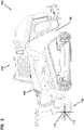
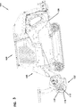
- FIGS. 1-3 illustrate a material reducing apparatus in accordance with the principles of the present disclosure.
- the material reducing apparatus is shown as a forestry machine 100 (also known, for example, as a forestry mower or forestry mulcher) including a material reducing head 102 carried by a vehicle 104.
- the vehicle 104 is depicted as a track loader, but could be any other type of vehicle, such as a wheeled or tracked tractor.
- the vehicle 104 includes a main frame 106.
- a linkage e.g., a boom 108 including a boom arm, a pair of spaced-apart boom arms, or other structures
- the boom 108 can be pivoted up and down to raise and lower the material reducing head 102 relative to the main frame 106.
- the material reducing head 102 can pivot to tilt forwardly and rearwardly relative to the main frame 106.
- the material reducing head 102 includes a rotary reducing component 110 (e.g., a rotor/drum) that is rotated about a central axis 112. At least one motor 114 can be provided for rotating the rotary reducing component 110 about the central axis 112.
- the rotary reducing component 110 can include a drum, shaft, or other main body which carries a plurality of reducing elements 116. During normal operation, when viewing the cross-section of the rotary reducing component 110 from the left side of the forestry machine 100 (as shown in FIG. 3 ), the rotary reducing component 110 rotates in a counter clockwise direction.
- the rotary reducing component 110 and reducing elements 116 can be utilized on a wide range of machines that utilize a rotary reducing component.
- the rotary reducing component 110 and reducing elements 116 can be used in a grinder machine such as a horizontal grinder, tub grinder, brush chipper or the like.
- a horizontal grinder can be found in U.S. Patent No. 9,168,535 ; an example of a tub grinder can be found in U.S. Patent No. 9,505,007 ; and an example of a brush chipper can be found in U.S. Patent No. 9,409,310 ; all of which are hereby incorporated by reference in their entirety.
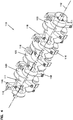
- FIG. 4 shows a perspective view of the rotary reducing component 110.
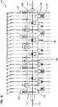
- FIG. 5 shows a front view of the rotary reducing component 110.
- the rotary reducing component 110 includes the plurality of reducing elements 116 mounted to a plurality of reducing element mounts 118.
- the reducing element mounts 118 are mounted to a main body 111 (i.e., a hollow shaft, a drum, a plurality of discs, a plurality of bars, etc.).
- the rotary reducing component 110 includes a plurality of depth control devices 120.
- the rotary reducing component 110 has a plurality of cutting paths (labeled C1-C24) spaced along the central axis 112 of the rotary reducing component 110. Each of the cutting paths is defined by or coincides with a single one of the reducing elements 116. Thus, during reducing, each path makes only one impact per revolution of the rotary reducing component 110.
- the rotary reducing component 110 can have a range of different qualities of reducing elements 116 mounted thereto. Further, the rotary reducing component 110 can be a variety of different diameters and lengths depending on its application.
- each of the reducing elements 116 is relatively sharp, block-like cutters suitable for chipping. As shown in FIG. 6 in the side view of the rotary reducing component 110, each of the reducing elements 116 includes a main body 122 and have a leading face 124 (e.g., a front side) and a trailing face 126 (e.g., a rear side). In some examples, the leading face 124 can be concave. In some examples, each reducing element 116 is at least partially ornamental in nature and features nonfunctional elements.
- each reducing element 116 is reversible in that each reducing element includes a pair of cutting heads 128a, 128b.
- the cutting heads 128a, 128b each include a cutting edge 130a, 130b that define a cutting plane. Further, the first and second cutting edge 130a, 130b also define at an interface between the leading face 124 and the trailing face 126.
- the edges 130a, 130b can be relatively sharp and can extend generally across an entire width of the main body 122 of the reducing element 116.
- the reducing element 116 can be mounted in a first orientation where the cutting edge 130a is positioned to encounter material that will be reduced.
- the reducing element 116 can be mounted in a first orientation where the cutting edge 130b is positioned to encounter material that will be reduced.
- the cutting edge 130a/130b that is performing the reducing operation can be referred to as the live cutting edge.
- the user can alter which cutting edge 130a, 130b is the live cutting edge by rotating the reducing element 116 to a position wherein the intended live cutting edge is positioned further away from the main body 111 of the rotary reducing component 110 as compared to the opposite, corresponding cutting edge 130a, 130b.
- the characteristic of the cutting edge e.g., sharpness and/or general cutting edge condition
- Each reducing element mount 118 is coupled with the main body 111 of the rotary reducing component 110 at a base 132 and coupled with a reducing element 116 at a reducing element mount leading face 134 via a fastener 136.
- Each reducing element mount 118 extends radially away from the main body 111 so that the reducing element mount leading face 134 faces in the direction of the rotation R.
- Each depth control device 120 is configured to limit the depth of cut of each corresponding reducing element 116. Further, each depth control device 120 aids in controlling depth of nearby or adjacent reducing elements in the case where the material to be cut is wider than a single reducing element. As shown in FIG. 5 , a depth control device 120 is paired with each reducing element 116. Specifically, the depth control device 120 is mounted to the main body 111 of the rotary reducing component 110 adjacent each reducing element 116 and reducing element mount 118 so that, during rotation of the rotary reducing component 110, the depth control device 120 passes by a point prior to the reducing element 116 and the reducing element mount 118.
- the depth of cut of each corresponding reducing element 116 is equal to the difference in radial height between an outer surface of the depth control device 120 and the cutting edge 130a.
- the depth control device 120 can be plate-like.
- the depth control device 120 can have an adjustable radial height.
- the depth control device 120 can have an increasing radial height from a leading edge 138 to a trailing edge 140, where the trailing edge 140 is nearer the reducing element 116 than the leading edge 138.
- FIG. 7 shows a schematic side view of the rotary reducing component 110.
- the reducing elements 116 define a reducing boundary D.
- the cutting edge 130a defines the reducing boundary D.
- the reducing boundary D has a diameter less than about 56 inches.
- the reducing boundary D has a diameter less than about 56 inches and greater than about 26 inches.
- the reducing boundary D has a diameter less than or equal to about 26 inches.
- the reducing boundary D has a diameter equal to about 18 inches.
- the diameter of the reducing boundary D can change over time as the reducing elements 116 wear and are sharpened.
- a portion of fastener 136 defines a fastener boundary F.
- the diameter of the fastener boundary F is less than the reducing boundary D.
- Such a configuration prevents the fastener 136 from first striking a material to be reduced before the reducing element 116. This prevents premature wear on the fastener 136.
- the diameter of the fastener boundary F is about 95% of the diameter of the reducing boundary D.
- the diameter of the fastener boundary F is less than the diameter of the reducing boundary D to allow for sufficient sharpening on the cutting edge 130a.
- the reducing element mount 118 defines a mount boundary M that has a diameter less than the diameter of the reducing boundary D.
- the mount boundary M has a diameter less than the diameter of the fastener boundary F.
- the depth control device 120 defines a depth control boundary B that is less the reducing boundary D, mount boundary M, and fastener boundary F.
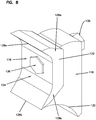
- FIG. 8 shows the reducing element 116 mounted to the reducing element mount 118 via the fastener 136.
- FIG. 9 shows an exploded view of the reducing element 116, the reducing element mount 118, and the fastener 136.
- the fastener 136 includes a bolt 142 and a nut 144.
- the reducing element 116 includes a fastener opening 146 having a central axis 147 that is configured to receive the bolt 142 of the fastener 136.
- the fastener opening 146 extends though the main body 122 from the leading face 124 to the trailing face 126.
- the fastener opening 146 can have a shape that is configured to receive a head 141 of the bolt 142.
- the reducing element mount 118 also includes a fastener opening 148 that is configured to receive the bolt 142 of the fastener 136.
- the fastener opening 148 extends through the reducing element mount leading face 134 to a trailing face 137.
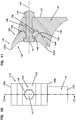
- FIG. 10 shows a front view of the reducing element 116 mounted to the reducing element mount 118 via the fastener 136.
- FIG. 11 shows a cross sectional view along line 11-11 in FIG. 10 .
- the fastener 136 specifically the bolt 142, passes through the fastener opening 146 of the reducing element 116 and the fastener opening 148 of the reducing element mount 118.
- the bolt 142 is secured to the nut 144 at the trailing face 137 of the reducing element mount.
- the head 141 of the bolt 142 is recessed in the main body 122 of the reducing element 116.
- the head 141 of the bolt 142 is positioned in contact with the trailing face 137 of the reducing element mount and the nut is in contact with the main body 122 of the reducing element 116.
- the reducing element 116 can include a pair of projections 150 extending from the trailing face 126.
- the pair of projections 150 are received and supported by a pair of recesses 152 disposed within the reducing element mount leading face 134 of the reducing element mount 118.
- the projections 150 are cylindrical in shape; however, they can be a variety of different shapes.
- the projections 150 are tapered.
- the recesses 152 are generally cylindrical in shape; however, they can be a variety of different shapes. In some examples, the recesses 152 are tapered.
- the reducing element mount 118 can also include a ledge 154 (e.g., a radial load support surface) adjacent the reducing element mount leading face 134 that is configured to support at least a portion of the trailing face 126 of the reducing element 116.
- the ledge 154 is configured to support the reducing element 116 against a force in a radial direction toward the base 132 of the reducing element mount 118, and specifically a force in a radial direction toward the central axis 112 of the rotary reducing component 110, as shown in FIG. 6 .
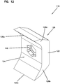
- FIG. 12 shows a perspective view of the reducing element 116 from the leading face 124. As shown, the cutting heads 128a, 128b extend away from the main body 122 of the reducing element to create a concave, leading face 124.
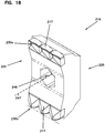
- FIG. 13 shows a perspective view of the reducing element 116 from the trailing face 126. As shown, the projections 150 extend from the trailing face 126.
- FIG 14 shows a front view of the reducing element 116 from the leading face 124.
- FIG. 15 shows a cross section of the reducing element 116 along line 15-15 in FIG. 14 .
- the leading face 124 includes a plurality of distinct surfaces. Specifically, the leading face 124 includes a central (i.e. main) surface 156, a first transition surface 158a, a second transition surface 158b, a first rake surface 160a, and a second rake surface 160b.
- the first transition surface 158a is between the first rake surface 160a and the central surface 156
- the second transition surface 158b is between the second rake surface 160b and the central surface 156.
- the first rake surface 160a helps to define the cutting edge 130a
- the second rake surface 160b helps to define the cutting edge 130b.
- the rake and transition surfaces 160a, 160b, 158a, 158b can each have a facetted construction comprising a plurality of sub surfaces.
- the central surface 156 can have a variety of different shapes and configuration. In some examples, the central surface 156 is planer. In other examples, the central surface 156 can have an assortment of angles and shapes.
- the first and second transition surfaces 158a, 158b each have a radius R 1 .
- the radius R 1 for both the first and second transition surfaces 158a, 158b is between about .25 inches and 1.25 inches.
- the radius R 1 is about 0.5 inches.
- the radius R 1 is about 1.0 inches.
- a horizontal reference plane A horizontally bisects the central surface 156 and passes through the central axis 147 of the fastener opening 146.
- the reducing element 116 is symmetrical about reference plane A.
- a vertical reference plane B vertically bisects the central surface 156, the first transition surface 158a, the second transition surface 158b, the first rake surface 160a, and the second rake surface 160b and passes through the central axis 147 of the fastener opening 146.
- the reducing element 116 is symmetrical about reference plane B.
- FIG. 15 also shows the fastener opening 146 having a first passage 162 and a second passage 164.
- the first passage 162 can be configured to receive the fastener 136 (e.g., the head 141 of the bolt 142 or the nut 144).
- the cutting edges 130a, 130b are linearly continuous across a width J of the reducing element 116.
- the cutting edges 130a, 130b are linearly discontinuous across the width J of the reducing element 116 but together form a linear cutting plane CP.
- the reducing element 116 can include a plurality of points that form a linear cutting edge.
- the reducing element 116 can include angled sub-cutting edges that form a single cutting edge.
- the angled cutting edges can form a leading point or edge(s) or a leading edge(s).
- the leading point or leading edge in such an example can form the cutting plane CP.
- the cutting edges 130a, 130b can be formed from the same material as the main body 122. In other examples, the cutting edges 130a, 130b can be formed from a material different from that used to construct the main body 122. In some examples, the cutting edges 130a, 130b can be formed from a single cutting insert or a plurality of cutting inserts. Such inserts can include, but not be limited to, a carbide insert.
- FIG. 16 shows a rear view of the reducing element 116 from the trailing face 126.
- the trailing face 126 i.e., a rear face or side
- the trailing face 126 includes a plurality of surfaces including a mounting face 166, a first body surface 168a, a second body surface 168b, a first relief surface 170a and a second relief surface 170b.
- the first body surface 168a is between and angled with the first relief surface 170a and the mounting face 166
- the second body surface 168b is between and angled with the second relief surface 170b and the mounting face 166.
- the first relief surface 170a helps to define the cutting edge 130a and the second relief surface 170b helps to define the cutting edge 130b.
- the first and second relief surfaces 170a, 170b are configured to be grinded down to sharpen the cutting edges 130a, 130b.
- the first and second body surfaces 168a, 168b are configured to be in contact with the ledge 154 of the reducing element mount 118 when the corresponding cutting edge 130a, 130b is not the live edge.
- FIG. 17 shows a side view of the reducing element 116. Because cutting heads 128a, 128b are substantially similar, only a set of references and relationships between components of the cutting head 128a are shown. It will be understood that the references and relationships between components at cutting head 128b are substantially similar those at cutting head 128a.
- a reference plane T is defined by both cutting edges 130a, 130b.
- a reference plane F i.e. a front face reference plane
- the reference plane F is defined generally by central surface 156 of the leading face 124 and is positioned parallel to the reference plane T.
- a reference plane H is positioned perpendicular to reference plane T.
- Reference plane H and reference plane F intersect at an angle ⁇ .
- the angle ⁇ is generally 90 degrees.
- a reference plane Q is shown to be defined by the rake surface 160a, and a reference plane U is shown to be defined by the relief surface 170a.
- Reference plane Q and reference plane U intersect at angle TI.
- angle TI is between about 25 degrees and 40 degrees.
- angle TI is between about 60 degrees and 90 degrees.
- the angle TI is about 35 degrees.
- the angle TI is about 70 degrees.
- Q intersects with the central axis 147 of the fastener opening 146.
- Q intersects with the central axis 147 at an angle QA.
- QA is less than 50 degrees.
- angle QA is about 46 degrees.
- the rake surface 160a is shown to have a length V.
- the length V is between about 0.5 inches and 1.2 inches. In other examples, the length V is between about 0.9 inches and 1.1 inches. In other examples still, the length V is about 1.07 inches.
- the cutting heads 128a, 128b each extend from the main body 122. As shown, a distance W is between the reference plane T, which passes through each cutting edge 130a, 130b, and the reference plane F that is defined by the central surface 156. In some examples, the distance W is between about .80 inches and about 1.2 inches. In some examples, the distance W is about 1.03 inches.
- a thickness X of the main body 122 is shown to be defined between the plane F defined by the central surface 156 of the leading face 124 and a plane M defined by the mounting face 166 of the trailing face 126.
- the thickness X is between about 0.8 inches and about 1.2 inches. In other examples, the thickness X is between about 0.9 inches and 1.1 inches. In other examples still, the thickness X is about 1.01 inches.
- the projections 150 each include a central axis P.
- the central axes P are generally perpendicular to plane F defined by the central surface 156.
- the central axes P are generally perpendicular to plane M defined by the mounting face 166. As shown, plane Q intersects the mounting face 166 at a point between the projections 150, and thereby between the central axes P.
- FIG. 18 shows a perspective view of a reversible reducing element 216 according to one embodiment of the present disclosure.
- the reducing element is substantially similar to the reducing element 116 described above.
- the reducing element 216 is at least partially ornamental in nature and features nonfunctional elements.
- the reducing element 216 has a leading face 224, a trailing face 226, a first cutting edge 230a, a second cutting edge 230b, and a fastener opening 246.
- the fastener opening 246 has a central axis 247.
- the reducing element 216 includes a tip insert 217.
- the reducing element 216 can include a plurality of inserts 217.
- the insert 217 can be a carbide insert. As shown, the tip inserts 217 define the cutting edges 230a, 230b.
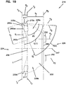
- FIG. 19 shows a side view of the reducing element 216.
- a reference plane T2 is defined by both cutting edges 230a, 230b.
- a reference plane F2 (i.e. a front face reference plane) is defined by a central (i.e. main) surface 256 of the leading face 224.
- the reference plane F2 is defined generally by central surface 256 of the leading face 224 and is positioned parallel to the reference plane T2.
- the reference plane H2 is positioned perpendicular to reference plane T2.
- the central surface 256 can have a variety of different shapes and configurations.
- the central surface 256 is planer.
- the central surface 256 can have an assortment of angles and shapes.
- Reference plane H2 and reference plane F2 intersect at an angle ⁇ 2.
- the angle ⁇ 2 is generally 90 degrees.
- a reference plane Q1 is shown to be defined by a rake surface 260a.
- a reference plane Q2 is shown to be defined by a rake surface 260aa, and a reference plane U2 is shown to be defined by a relief surface 270a.
- Reference plane Q1 and reference plane U2 intersect at angle TI(1).
- Reference plane Q2 and reference plane U2 intersect at angle TI(2).
- angle TI(1) is between about 60 degrees and 90 degrees.
- angle TI(1) is about 80 degrees.
- angle TI(2) is between about 50 degrees and 70 degrees.
- angle TI(2) is about 63 degrees.
- the rake surfaces 260a, 260aa combined have a length V2 to the central surface 256.
- the length V2 is between about 1.0 inches and 2.0 inches. In some examples, the length V2 is about 1.6 inches.
- the cutting heads 228a, 228b each extend from a main body 222. As shown, a distance W2 is between the reference plane T2, that passes through the leading most point of cutting edge 230a, 230b, and the reference plane F2 that is defined by the central surface 256. In some examples, the distance W2 is between about .25 inches and about 1.0 inches. In some examples, the distance W2 is about 0.5 inches.
- a thickness X2 of the main body 222 is shown to be defined between the reference plane F2 defined by the central surface 256 of the leading face 224 and a plane M2 defined by a mounting face 266 of the trailing face 226.
- the thickness X2 is between about 1.0 inches and about 2.0 inches. In other examples, the thickness X2 is about 1.5 inches.
- Projections 250 each include a central axis P2.
- the central axes P2 are generally perpendicular to reference plane F2 defined by the central surface 256.
- the central axes P2 are generally perpendicular to plane M2 defined by the mounting face 266.
- FIG. 20 shows a perspective view of a reversible reducing element 316 according to one embodiment of the present disclosure.
- the reducing element is substantially similar to the reducing elements 116, 216 described above.
- the reducing element 316 is at least partially ornamental in nature and features nonfunctional elements.
- the reducing element 316 has a leading face 324, a trailing face 326, a first cutting edge 330a, a second cutting edge 330b, and a fastener opening 346.
- the fastener opening 346 has a central axis 347.
- the reducing element 316 includes a tip insert 317.
- the reducing element 316 can include a plurality of inserts 317.
- the insert 317 can be a carbide insert. As shown, the tip inserts 317 define the cutting edges 330a, 330b.
- FIG. 21 shows a side view of the reducing element 316.
- a reference plane T3 is defined by both cutting edges 330a, 330b.
- a reference plane F2 is defined by a central (i.e. main) surface 356 of the leading face 324.
- the reference plane F3 i.e. a front face reference plane
- the central surface 356 is defined generally by central surface 356 of the leading face 324 and is positioned parallel to the reference plane T3.
- a reference plane H3 is positioned perpendicular to reference plane T3.
- the central surface 356 can have a variety of different shapes and configuration.
- the central surface 356 is planer.
- the central surface 356 can have an assortment of angles and shapes.
- Reference plane H3 and reference plane F3 intersect at an angle ⁇ 3.
- the angle ⁇ 3 is generally 90 degrees.
- a reference plane Q3 is shown to be defined by a rake surface 360a and a reference plane U3 is shown to be defined by a relief surface 370a.
- Reference plane Q3 and reference plane U3 intersect at angle TI(3).
- angle TI(3) is between about 60 degrees and 90 degrees. In some examples, angle TI(3) is about 72 degrees.
- the rake surface 360a has a length V3 to the central surface 356.
- the length V3 is between about 1.0 inches and 2.0 inches. In some examples, the length V3 is about 1.6 inches.
- Cutting heads 328a, 328b each extend from a main body 322. As shown, a distance W3 is between the reference plane T3, that passes through the leading most point of cutting edge 330a, 330b, and the reference plane F3 that is defined by the central surface 356. In some examples, the distance W3 is between about .25 inches and about 1.0 inches. In some examples, the distance W3 is about 0.45 inches.
- a thickness X3 of the main body 322 is shown to be defined between the reference plane F3 defined by the central surface 356 of the leading face 324 and a plane M3 defined by a mounting face 366 of the trailing face 326.
- the thickness X3 is between about 1.0 inches and about 2.0 inches. In other examples, the thickness X3 is about 1.5 inches.
- Projections 350 each include a central axis P3.
- the central axes P3 are generally perpendicular to reference plane F3 defined by the central surface 356.
- the central axes P3 are generally perpendicular to plane M3 defined by the mounting face 266.
- FIG. 22 shows the reducing element 116 mounted to the rotary reducing component 110 via the reducing element mount 118.
- a reference plane Y i.e. a radial reference plane
- a reference plane Z i.e. a chip direction plane
- Reference plane Z intersects with reference plane F, which is defined by the central surface 156 of the leading face 124, at an angle ⁇ .
- angle ⁇ is referred to as a chip curl angle.
- angle ⁇ is between about 82 degrees and about 102 degrees when the reducing boundary D is equal or less than 26 inches. In other examples, the angle ⁇ is between about 79 degrees and about 97 degrees when the reducing boundary D is between about 26 inches and 56 inches. In other examples, the angle ⁇ is about 91 degrees regardless of diameter of the reducing diameter D. In some examples, the angle ⁇ is about 91 degrees when the reducing boundary D is less than or equal to about 56 inches.
- a rake angle RA is defined between the first rake surface 160a and the reference plane Y.
- the rake angle RA in one example, can be greater than or equal to 30 degrees. In some examples, the rake angle RA is about 42 degrees.
- the mounting plane M is shown to be offset a distance OM from the central axis 112 in a direction opposite of that of the rotation direction R of the rotary reducing component 110 along the central axis 147 of the rotary reducing component 110. In some examples, the mounting plane M is offset a distance that is about 10% of the diameter of the rotary reducing component 110. In some examples, the distance OM that is equal to at least the thickness X of the reducing element (shown in FIG. 17 ). The mounting plane M is also shown to be offset from the reference plane Y in a direction opposite of that of the rotation direction R of the rotary reducing component 110.
- FIG.23 shows the reducing element 216 mounted to the rotary reducing component 110 via the reducing element mount 118.
- the reducing element 216 forms the angle ⁇ with reference plane Z and reference plane F2.
- angle ⁇ is between about 82 degrees and about 102 degrees when the reducing boundary D is equal to or less than 26 inches.
- the angle ⁇ is between about 79 degrees and about 97 degrees when the reducing boundary D is between about 26 inches and 56 inches.
- the angle ⁇ is about 91 degrees regardless of diameter of the reducing diameter D.
- the angle ⁇ is about 91 degrees when the reducing boundary D is less than or equal to about 56 inches.
- a rake angle RA2 is defined between the first rake surface 260a and the reference plane Y. In some examples, the rake angle RA2 is between about 0 degrees and 20 degrees. In one example, the rake angle RA2 is about 5 degrees. In other examples, the rake angle RA2 is about 14 degrees.
- FIG. 24 shows the reducing element 316 mounted to the rotary reducing component 110 via the reducing element mount 118.
- the reducing element 316 forms the angle ⁇ with reference plane Z and reference plane F3.
- angle ⁇ is between about 82 degrees and about 102 degrees when the reducing boundary D is equal to or less than 26 inches.
- the angle ⁇ is between about 79 degrees and about 97 degrees when the reducing boundary D is between about 26 inches and 56 inches.
- the angle ⁇ is about 91 degrees regardless of diameter of the reducing diameter D.
- the angle ⁇ is about 91 degrees when the reducing boundary D is less than or equal to about 56 inches.
- a rake angle RA3 is defined between the first rake surface 360a and the reference plane Y. In some examples, the rake angle RA3 is between about 0 degrees and 20 degrees. In one example, the rake angle RA3 is about 5 degrees. In other examples, the rake angle RA3 is about 14 degrees.
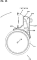
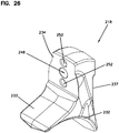
- FIGS. 25-27 show a reducing element mount 218 according to one embodiment of the present disclosure.
- the reducing element mount 218 is substantially similar to the reducing element mount 118 described above.
- the reducing element mount 218 can be forged.
- the reducing element mount 218 is configured to receive any of the reducing elements 116, 216, 316 described above.
- the reducing element mount 218 is configured to be coupled with the main body 111 of the rotary reducing component 110 at a base 232 and coupled with a reducing element 116, 216, 316 at a reducing element mount leading face 234 via the fastener 136 (shown in FIG. 9 ).
- Each reducing element mount 218 extends radially away from the main body 111 so that the reducing element mount leading face 234 faces in the direction of the rotation R.
- the base 232 includes a portion 233 that extends in front of the reducing element 116, 216, 316 in the direction of rotation R when the reducing element mount 218 and reducing element 116, 216, 316 are mounted to the main body 111.
- the portion 233 can include a ramped shape extending opposite the direction of rotation to the leading face 234, being angled away from the main body 111.
- the portion 233 can be configured to support and contact a portion of the reducing element 116, 216, 316.
- the reducing element mount 218 includes a fastener opening 248 that is configured to receive the bolt 142 of the fastener 136.
- the fastener opening 248 extends through the reducing element mount leading face 234 to a trailing face 237.
- the reducing element mount 218 can also include a pair of recesses 252 disposed within the reducing element mount leading face 234 of the reducing element mount 218.
- the recesses 252 are generally cylindrical in shape; however, they can be a variety of different shapes.
- the recesses 252 are tapered.
- FIG. 28 shows another perspective view of the rotary reducing component 110.
- the reducing elements 116 are mounted to the reducing element mounts 118 that are mounted to a main body 111.
- the depicted rotary reducing component 110 includes 24 reducing elements 116 spaced along the length of the main body 111 of the rotatory reducing component 110.
- the rotary reducing component 110 includes a plurality of depth control devices 420 that are configured to both aid in preventing the rotary reducing component from becoming jammed during operation and to aid in controlling the size of a material chip created by the reducing elements 116 during operation by limiting their depth of cut during operation. While reducing elements 116 are shown and used in the following description, reducing elements 216, 316 and a variety of other different types of reducing elements can be utilized with the depth control devices 420.
- Each depth control device 420 is paired with a reducing element 116. Specifically, each depth control device 420 is mounted to the main body 111 of the rotary reducing component 110 circumferentially adjacent each reducing element 116 and reducing element mount 118 so that, during rotation of the rotary reducing component 110, the depth control device 420 passes by a point prior to the reducing element 116 and the reducing element mount 118.
- each depth control device 420 can be plate-like. In other examples, each depth control device 420 can include a plurality of individual components.
- each depth control devices 420 can be one of a plurality of different types and shapes.
- each depth control devices 420 can have one of a plurality of three different types to maximize the performance of the rotary reducing component 110.
- the depth control devices 420 can be configured to have a minimal radial height at portions of the depth control devices 420 that are immediately axially adjacent reducing elements 116 of which the respective depth control device 420 is not circumferentially adjacent.
- FIG. 29 shows a schematic view of an example arrangement of the depth control devices 420 on the main body 111 of the rotary reducing component 110 surrounding a single reducing element 116.
- FIG. 29 is meant to be schematic and illustrative of the arrangement around a single reducing element 116.
- a depth control device 420b is circumferentially aligned with the reducing element 116.
- the depth control device 420b can be centered with the reducing element 116.
- depth control devices 420a, 420c are shown positioned axially adjacent on the main body 111 from the reducing element 116.
- the reducing element 116 and the associated depth control device 420b are shown positioned between the depth control devices 420a, 420b.
- a chip evacuation pocket CEP is schematically shown with dashed lines surrounding the reducing element 116.
- the chip evacuation pocket CEP is a pocket in which the chips move away from the reducing element 116 during operation of the rotary reducing component 110.
- the chips are formed from material which the reducing element 116 contacts (i.e., reduces).
- reduces material which the reducing element 116 contacts
- the chip evacuation pocket CEP is generally U-shaped. Specifically, the chip evacuation pocket CEP has a leading most boundary 400 in the rotation direction R that is defined by at least the depth control device 420b. Side boundaries 402 and 404 extend past the depth control devices 420a, 420c in opposite axial directions from sides 115 of the reducing element 116. In some examples, the depth control devices 420a, 420b have configurations in which pocket portions 422a, 422c of the depth control devices 420a, 420c that correspond with the side boundaries 402, 404 of the chip evacuation pocket CEP and have radial heights that are substantially reduced radial heights to allow for proper chip movement away from the reducing element 116.
- all reducing elements 116 positioned on the main body 111 of the rotary reducing component 110 have a similar chip evacuation pocket CEP as shown in FIG. 29 .
- the reducing elements 116 that are positioned immediately adjacent the ends of the main body 111 have at least a portion of the chip evacuation pocket CEP associated with them.
- the chip evacuation pocket also extends radially away from the main body 111 to the cutting edge 130a.
- the depth control devices 420a, 420c also each circumferentially align with reducing elements 116 positioned on the main body 111. Therefore, successive axially adjacent depth control devices 420 are each circumferentially aligned with a reducing element 116 while also providing pocket portions 422 that are axially adjacent successive axially adjacent reducing elements 116. Such an arrangement maximizes the size of the chip evacuation pocket CEP and provides depth control.
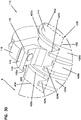
- FIG. 30 shows a front perspective view of a first example of the arrangement shown in FIG. 29 .
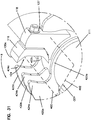
- FIG. 31 shows a rear perspective view of the first example of the arrangement shown in FIG. 29 .
- the depth control devices 420a, 420c are axially spaced along the main body 111 from the sides 115 of the reducing element 116 and the depth control device 420b. Further, the pocket portions 422a, 422c of the depth control devices 420a, 420c are shown to have a radial heights from the main body 111 that are substantially less than a radial height of the reducing element 116.
- the leading most boundary 400 of the chip evacuation pocket CEP is defined by depth extensions 424a, 424b, 424c of the depth control devices 420a, 420b, 420c.
- the depth extensions 424a, 424b, 424c have radial heights from the main body 111 greater than the pocket portions 422a, 422c.
- the depth extensions 424a, 424b, 424c have radial heights equal to or greater than half the radial height of the reducing element 116.
- the depth extensions 424a, 424b, 424c can aid in protecting the reducing element 116 and aid in reducing the depth of cut by the cutting edge 130a of the reducing element 116.
- the depth extensions 424a, 424b, 424c can have hook-like configurations and be circumferentially spaced from the leading face 124 of the reducing element 116. In some examples, the depth extensions 424a, 424b, 424c have equal radial heights. In other examples, the depth extensions 424a, 424b, 424c have varying radial heights.
- FIG. 32 shows a front perspective view of a second example of the arrangement shown in FIG. 29 .
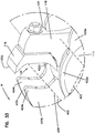
- FIG. 33 shows a rear perspective view of the second example of the arrangement shown in FIG. 29 .
- the leading most boundary 400 of the chip evacuation pocket CEP is defined by depth extensions 424a, 424b of the depth control devices 420a, 420b.
- the pocket portion 422c of the depth control device 420c is positioned axially adjacent the depth extensions 424a, 424b.
- the leading most boundary 400 of the chip evacuation pocket CEP can be defined by depth extensions 424b, 424c of the depth control devices 420b, 420c, and the pocket portion 422a of the depth control device 420a is positioned axially adjacent the depth extensions 424b, 424c.
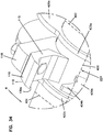
- FIG. 34 shows a front perspective view of a third example of the arrangement shown in FIG. 29 .
- FIG. 35 shows a rear perspective view of the third example of the arrangement shown in FIG. 29 .
- the leading most boundary 400 of the chip evacuation pocket CEP is defined only by the depth extension 424b of the depth control device 420b.
- the pocket portions 422a, 422c of the depth control devices 420a, 420c are positioned axially adjacent the depth extension 424b.
- FIGS. 36-38 show side views of example depth control devices 430, 432, 434.
- the depth control devices 430, 432, 434 can be disposed on the main body 111 in a variety of different orders and patterns.
- the depth control devices 430, 432, 434 can be used as depth control devices 420a, 420b, and 420c in a variety of different orders, depending on the position of the reducing elements on the main body 111 of the rotary reducing component 110.
- the depth control device 430 corresponds with depth control device 420a
- the depth control device 432 corresponds with depth control device 420b
- the depth control device 434 corresponds with depth control device 420c.
- FIG. 36 shows the depth control device 430 positioned circumferentially adjacent an example reducing element 216.
- Reducing elements 116 and 316 can also be used.
- the reducing element 216 has a radial height of RH1 from the main body 111.
- the depth control device 430 includes a leading depth control portion 438, a trailing depth control portion 440, a pocket portion 442 between the leading and trailing depth control portions 438, 440, and a reducing element gap 444 between the leading and trailing depth control portions 438, 440.
- the leading depth control portion 438 is positioned in front of the reducing element 216 in the direction of rotation R.
- the leading depth control portion 438 includes a depth extension 446 that has a radial height RH2 from the main body 111.
- the leading depth control portion 438 has a consistent radial height.
- the leading depth control portion 438 has a decreasing height in the direction of rotation R.
- the leading depth control portion 438 has an increasing height in the direction of rotation R
- the trailing depth control portion 440 is positioned behind the reducing element 216 in a direction opposite the direction of rotation R.
- the trailing depth control portion 440 includes a depth extension 448 that has a radial height RH3 from the main body 111.
- the trailing depth control portion 440 has a consistent radial height.
- the trailing depth control portion 440 has a decreasing height in the direction of rotation R.
- the trailing depth control portion 440 has an increasing height in the direction of rotation R.
- the pocket portion 442 is positioned between the leading depth control portion 438 and the trailing depth control portion 440.
- the pocket portion 442 has a radial height RH4 from the main body 111.
- the depth control device 430 is constructed of only the leading and trailing depth control portions 438, 440. When installed on the main body 111, the leading and trailing depth control portions 438, 440 can be circumferentially spaced from one another to create the pocket 442; therefore, in such an example, the radial height RH4 of the pocket portion 442 would be equal to 0.
- the depth control device 430 can have a leading ramped surface 443 between the leading depth control portion 438 and the pocket 442.
- the pocket portion 442 corresponds with the at least one of the pocket portions 422a, 422b shown in FIGS. 30-35
- the reducing element gap 444 is a gap defined by the depth control device 430 so as to accommodate the reducing element 216 and the reducing element mount 218.
- the trailing depth control portion 440 can be positioned in contact with the trailing face 237 of the reducing element mount 218.
- the leading depth control portion 438, specifically the depth extension 446 can be circumferentially spaced in the direction of rotation R from the leading face 224 of the reducing element 216.
- the radial heights RH2 and RH3 of the depth extensions 446,448 are equal to or greater than 50 percent of the radial height RH1 of the reducing element 216. In some examples, the radial heights RH5 and RH6 of the depth extensions 458, 460 are equal to or greater than 75 percent of the radial height RH1 of the reducing element 216. In some examples, the radial height RH4 of the pocket portion 442 is equal to or less than 25 percent of the radial height RH1 of the reducing element 216. In some examples, the radial height RH4 is equal to or less than 15 percent of the radial height RH1 of the reducing element 216. In some examples, the radial height RH4 is equal to or less than 10 percent of the radial height RH1 of the reducing element 216.
- FIG. 37 shown the depth control device 432 positioned circumferentially adjacent an example reducing element 216.
- Reducing elements 116 and 316 can also be used.
- the reducing element 216 has the radial height of RH1 from the main body 111.
- the depth control device 432 includes a leading depth control portion 450, a trailing depth control portion 452, a pocket portion 454 between the leading and trailing depth control portions 450, 452, and a reducing element gap 456 between the leading and trailing depth control portions 450, 452.
- the leading depth control portion 450 extends a greater distance along the circumference of the main body 111 as compared to the leading depth control portion 438 of the depth control device 430.
- the leading depth control portion 450 is positioned in front of the reducing element 216 in the direction of rotation R.
- the leading depth control portion 450 includes a depth extension 458 that has a radial height RH5 from the main body 111.
- the leading depth control portion 450 has a consistent radial height.
- the leading depth control portion 450 has a decreasing height in the direction of rotation R.
- the leading depth control portion 450 has an increasing height in the direction of rotation R
- the trailing depth control portion 452 is positioned behind the reducing element 216 in a direction opposite the direction of rotation R.
- the trailing depth control portion 452 includes a depth extension 460 that has a radial height RH6 from the main body 111.
- the trailing depth control portion 452 is substantially similar to the trailing depth control portion 440 of the depth control device 430.
- the trailing depth control portion 452 has a consistent radial height.
- the trailing depth control portion 452 has a decreasing height in the direction of rotation R.
- the trailing depth control portion 452 has an increasing height in the direction of rotation R.
- the pocket portion 454 is positioned between the leading depth control portion 450 and the trailing depth control portion 452.
- the pocket portion 454 has a radial height RH7 from the main body 111.
- the depth control device 432 is constructed of only the leading and trailing depth control portions 450, 452. When installed on the main body 111, the leading and trailing depth control portions 450, 452 can be circumferentially spaced from one another to create the pocket 454; therefore, in such an example, the radial height RH7 of the pocket portion 442 would be equal to 0.
- the depth control device 432 can have a leading ramped surface 455 between the leading depth control portion 450 and the pocket 454.
- the pocket 454 extends a lesser distance along the circumference of the main body 111 as compared to the pocket portion 442 of the depth control device 430.
- the pocket portion 454 corresponds with the at least one of the pocket portions 422a, 422b shown in FIGS. 30-35 .
- the reducing element gap 456 is a gap defined by the depth control device 432 so as to accommodate the reducing element 216 and the reducing element mount 218.
- the reducing element gap 456 is substantially similar to the reducing element gap 444 of the depth control device 430 described above.
- the trailing depth control portion 452 can be positioned in contact with the trailing face 237 of the reducing element mount 218.
- the leading depth control portion 450, specifically the depth extension 458, can be circumferentially spaced in the direction of rotation R from the leading face 224 of the reducing element 216.
- the radial heights RH5 and RH6 of the depth extensions 458, 460 are equal to or greater than 50 percent of the radial height RH1 of the reducing element 216. In some examples, the radial heights RH5 and RH6 of the depth extensions 458, 460 are equal to or greater than 75 percent of the radial height RH1 of the reducing element 216. In some examples, the radial height RH7 of the pocket portion 454 is equal to or less than 25 percent of the radial height RH1 of the reducing element 216. In some examples, the radial height RH7 is equal to or less than 15 percent of the radial height RH1 of the reducing element 216. In some examples, the radial height RH7 is equal to or less than 10 percent of the radial height RH1 of the reducing element 216.
- FIG. 38 shows the depth control device 434 positioned circumferentially adjacent an example reducing element 116.
- Reducing elements 216 and 316 can also be used.
- the reducing element 116 has the radial height of RH1 from the main body 111.
- the depth control device 434 includes a leading depth control portion 462, a trailing depth control portion 464, a pocket portion 466 between the leading and trailing depth control portions 462, 464, and a reducing element gap 468 between the leading and trailing depth control portions 462, 464.
- the leading depth control portion 462 extends a greater distance along the circumference of the main body 111 as compared to the leading depth control portion 438 of the depth control device 430 but a lesser circumferential distance than the leading depth control portion 450 of the depth control device 432.
- the leading depth control portion 462 is positioned in front of the reducing element 116 in the direction of rotation R.
- the leading depth control portion 462 includes a depth extension 470 that has a radial height RH8 from the main body 111.
- the leading depth control portion 462 has a consistent radial height.
- the leading depth control portion 462 has a decreasing height in the direction of rotation R.
- the leading depth control portion 462 has an increasing height in the direction of rotation R.
- the trailing depth control portion 464 is positioned behind the reducing element 116 in a direction opposite the direction of rotation R.
- the trailing depth control portion 464 includes a depth extension 472 that has a radial height RH9 from the main body 111.
- the trailing depth control portion 452 extends a lesser distance along the circumference of the main body 111 as compared to the trailing depth control portion 440 of the depth control device 430 and the trailing depth control portion 452 of the depth control device 432.
- the trailing depth control portion 464 has a consistent radial height.
- the trailing depth control portion 464 has a decreasing height in the direction of rotation R.
- the trailing depth control portion 464 has an increasing height in the direction of rotation R.
- the pocket portion 466 is positioned between the leading depth control portion 462 and the trailing depth control portion 464.
- the pocket portion 466 has a radial height RH10 from the main body 111.
- the depth control device 434 is constructed of only the leading and trailing depth control portions 462, 464. When installed on the main body 111, the leading and trailing depth control portions 462, 464, can be circumferentially spaced from one another to create the pocket 466; therefore, in such an example, the radial height RH10 of the pocket portion 466 would be equal to 0.
- the depth control device 434 can have a leading ramped surface 467 between the leading depth control portion 462 and the pocket 466.
- the pocket 466 extends a lesser distance along the circumference of the main body 111 as compared to the pocket portion 442 of the depth control device 430.
- the pocket portion 466 corresponds with the at least one of the pocket portions 422a, 422b shown in FIGS. 30-35 .
- the reducing element gap 468 is a gap defined by the depth control device 434 so as to accommodate the reducing element 116 and the reducing element mount 118.
- the reducing element gap 456 is substantially similar to the reducing element gaps 444, 456 of the depth control devices 430, 432 described above.
- the trailing depth control portion 464 can be positioned in contact with the trailing face 137 of the rotary reducing element mount 118.
- the leading depth control portion 462, specifically the depth extension 470 can be circumferentially spaced in the direction of rotation R from the leading face 124 of the reducing element 116.
- the radial heights RH8 and RH9 of the depth extensions 470, 472 are equal to or greater than 50 percent of the radial height RH1 of the reducing element 116. In some examples, the radial heights RH8 and RH9 of the depth extensions 470, 472 are equal to or greater than 75 percent of the radial height RH1 of the reducing element 116. In some examples, the radial height RH10 of the pocket portion 454 is equal to or less than 25 percent of the radial height RH1 of the reducing element 116. In some examples, the radial height RH10 is equal to or less than 15 percent of the radial height RH1 of the reducing element 116. In some examples, the radial height RH10 is equal to or less than 10 percent of the radial height RH1 of the reducing element 116.
- An embodiment of the material reducing apparatus may include any one or more, and any combination of, the examples described below.
Landscapes
- Life Sciences & Earth Sciences (AREA)
- Environmental Sciences (AREA)
- Engineering & Computer Science (AREA)
- Food Science & Technology (AREA)
- Forests & Forestry (AREA)
- Ecology (AREA)
- Biodiversity & Conservation Biology (AREA)
- Mechanical Engineering (AREA)
- Soil Sciences (AREA)
- Harvester Elements (AREA)
- Crushing And Pulverization Processes (AREA)
- Apparatuses For Bulk Treatment Of Fruits And Vegetables And Apparatuses For Preparing Feeds (AREA)
- Perforating, Stamping-Out Or Severing By Means Other Than Cutting (AREA)
Abstract
Description
- Material reducing machines are machines used to reduce the size of material by processes such as mulching, chipping, grinding, cutting, or like actions. A typical material reducing machine includes a rotary reducing component that reduces material as the material reducing component rotates about a central axis. In certain examples, the rotary reducing component works in combination with other structures such as screens or anvils to facilitate the material reduction process. In certain examples, the rotary reducing component includes a main rotating body (e.g., a rotor, drum, plate stack, or like structures) and a plurality of reducing elements (e.g., knives, cutters, reducing elements, blades, hammers, teeth, or like structures) carried by the main rotating body. In certain examples, the reducing elements are positioned about a circumference of the main rotating body and are configured to define a circular cutting boundary as the rotary reducing component is rotated about its central axis.
- A forestry mower is an example of one type of material reducing machine. A forestry mower typically includes a vehicle such as a tractor or skid-steer vehicle. A material reducing head is coupled to the vehicle (e.g., by a pivot arm or boom). The material reducing head includes a rotary reducing component, which often incorporates a rotating drum that carries a plurality of reducing elements (e.g., blades, teeth, etc.). The material reducing head can be raised and lowered relative to the vehicle, and can also be pivoted/tilted forward and backward relative to the vehicle. By raising the reducing head and tilting the reducing head back, the forestry mower can be used to strip branches from trees and other aerial applications. By lowering the reducing head and pivoting the reducing head forward, the forestry mower can readily be used to clear brush, branches, and other material along the ground.
- The design of reducing elements varies drastically for a wide range of applications. However, the design of reducing elements can drastically affect the operation of the material reducing machine. For example, the arrangement of a cutting element can reduce both the effectiveness and efficiency of a material reducing machine.
- Therefore, improvements in reducing element design are needed.
- The present disclosure relates generally to a material reducing apparatus. In one possible configuration, and by non-limiting example, a tooth having an increased chipping productivity is disclosed.
- In one example of the present disclosure, a material reducing apparatus is disclosed. The material reducing apparatus includes a rotary reducing component that has a central rotational axis. The rotary reducing component being rotatable in a reducing direction. The material reducing apparatus includes a reducing element mount attached to the rotary reducing component and a reversible reducing element mounted to the reducing element mount. The reducing element includes a leading front side having a main front face, a first cutting edge, and an opposite second cutting edge being radially inwardly positioned closer to the central rotational axis from the first cutting edge. The reducing element including a trailing rear side having a mounting face and a front face reference plane defined by the main front face. The material reducing apparatus includes a radial reference plane that is defined by the leading most point of the first cutting edge in the reducing direction and the central rotation axis of the rotary reducing component. The material reducing apparatus includes a chip direction plane that is perpendicular with the radial reference plane and passing through the leading most part of the first cutting edge. The chip direction plane and the front face reference plane are angled with respect to one another at a chip curl angle. The chip curl angle is between about 82 degrees and 102 degrees. The rotary reducing component has a reducing boundary defined by the outer most cutting edge of the first and second cutting edges from the rotary reducing component. The reducing boundary has a diameter less than or equal to about 26 inches.
- In another example of the present disclosure, a material reducing apparatus is disclosed. The material reducing apparatus includes a rotary reducing component that has a central rotational axis. The rotary reducing component being rotatable in a reducing direction. The material reducing apparatus includes a reducing element mount attached to the rotary reducing component and a reversible reducing element mounted to the reducing element mount. The reducing element includes a leading front side having a main front face, a first cutting edge, and an opposite second cutting edge being radially inwardly positioned closer to the central rotational axis from the first cutting edge. The reducing element including a trailing rear side having a mounting face and a front face reference plane defined by the main front face. The material reducing apparatus includes a radial reference plane that is defined by the leading most point of the first cutting edge in the reducing direction and the central rotation axis of the rotary reducing component. The material reducing apparatus includes a chip direction plane that is perpendicular with the radial reference plane and passing through the leading most part of the first cutting edge. The chip direction plane and the front face reference plane are angled with respect to one another at a chip curl angle. The chip curl angle is between about 79 degrees and about 97 degrees. The rotary reducing component has a reducing boundary defined by the outer most cutting edge of the first and second cutting edges from the rotary reducing component. The reducing boundary has a diameter greater than or equal to 26 inches and less than or equal to about 56 inches.
- In another example, a material reducing apparatus is disclosed. The material reducing apparatus includes a rotary reducing component having a central rotational axis. The rotary reducing component is rotatable in a reducing direction. The material reducing apparatus includes a reducing element mount attached to the rotary reducing component and a reducing element mounted to the reducing element mount. The reducing element includes a leading face that has a cutting edge. The reducing element includes a pair of side faces that extend from the leading face to a rear trailing face. The rear trailing face is mounted to the reducing element mount and the side faces are axially spaced from one another on the rotary reducing component. The reducing element has a radial height extending away from the rotary reducing component. The material reducing apparatus includes at least one chip evacuation arrangement that includes a first depth control structure that has a reducing element portion circumferentially aligned and spaced from the leading face of reducing element on the rotary reducing component. The reducing element portion has a radial depth being at least half of the radial height of the reducing element. The chip evacuation arrangement includes a second depth control structure positioned axially adjacent a side of the reducing element. The second depth control structure has a radial height immediately axially adjacent to the reducing element that is less than or equal to 25% of the radial height of the reducing element. The chip evacuation arrangement includes a third depth control structure positioned axially adjacent the side of the reducing element, opposite the second depth control structure. The third depth control structure has a radial height immediately axially adjacent to the reducing element that is less than or equal to 25% of the radial height of the reducing element.
- A variety of additional aspects will be set forth in the description that follows. The aspects can relate to individual features and to combinations of features. It is to be understood that both the foregoing general description and the following detailed description are exemplary and explanatory only and are not restrictive of the broad inventive concepts upon which the embodiments disclosed herein are based.
- The following drawings are illustrative of particular embodiments of the present disclosure and therefore do not limit the scope of the present disclosure. The drawings are not to scale and are intended for use in conjunction with the explanations in the following detailed description. Embodiments of the present disclosure will hereinafter be described in conjunction with the appended drawings, wherein like numerals denote like elements.
-
FIG. 1 illustrates a perspective view of a material reducing apparatus according to one embodiment of the present disclosure. -
FIG. 2 illustrates a side view of the material reducing apparatus ofFIG. 1 . -
FIG. 3 illustrates a schematic longitudinal cross section of the material reducing apparatus ofFIG. 1 . -
FIG. 4 illustrates a perspective view of a rotary reducing component, according to one embodiment of the present disclosure. -
FIG. 5 illustrates a front view of the rotary reducing component ofFIG. 4 . -
FIG. 6 illustrates a side view of the rotary reducing component ofFIG. 4 . -
FIG. 7 illustrates a schematic side view of the rotary reducing component ofFIG. 4 . -
FIG. 8 illustrates a perspective view of a reducing element and a reducing element mount, according to one embodiment of the present disclosure. -
FIG. 9 illustrates an exploded view of the reducing element and the reducing element mount ofFIG. 8 . -
FIG. 10 illustrates a front view of the reducing element and the reducing element mount ofFIG. 8 . -
FIG. 11 illustrates a cross-sectional view of the reducing element and the reducing element mount along line 11-11 inFIG. 10 . -
FIG. 12 illustrates a front perspective view of the reducing element ofFIG. 8 . -
FIG. 13 illustrates a rear perspective view of the reducing element ofFIG. 8 . -
FIG. 14 illustrates a front view of the reducing element ofFIG. 8 . -
FIG. 15 illustrates a cross-sectional view of the reducing element along line 15-15 inFIG. 14 . -
FIG. 16 illustrates a rear view of the reducing element ofFIG. 8 . -
FIG. 17 illustrates a side view of the reducing element ofFIG. 8 . -
FIG. 18 illustrates a front perspective view of a reducing element, according to one embodiment of the present disclosure. -
FIG. 19 illustrates a side view of the reducing element ofFIG. 18 . -
FIG. 20 illustrates a front perspective view of a reducing element, according to one embodiment of the present disclosure. -
FIG. 21 illustrates a side view of the reducing element ofFIG. 20 . -
FIG. 22 illustrates a schematic side view of the reducing element ofFIG. 8 mounted to the rotary reducing element ofFIG. 4 . -
FIG. 23 illustrates a schematic side view of the reducing element ofFIG. 18 mounted to the rotary reducing element ofFIG. 4 . -
FIG. 24 illustrates a schematic side view of the reducing element ofFIG. 20 mounted to the rotary reducing element ofFIG. 4 . -
FIG. 25 illustrates a side view of a reducing element mount, according to one embodiment of the present disclosure. -
FIG. 26 illustrates a front perspective view of the reducing element mount ofFIG. 25 . -
FIG. 27 illustrates a rear perspective view of the reducing element mount ofFIG. 25 . -
FIG. 28 illustrates a perspective view of a rotary reducing component, according to one embodiment of the present disclosure. -
FIG. 29 illustrates a top schematic view of a portion of the rotary reducing component ofFIG. 28 . -
FIG. 30 illustrates a front perspective view of a portion of the rotary reducing component ofFIG. 28 . -
FIG. 31 illustrates a rear perspective view of a portion of the rotary reducing component ofFIG. 28 . -
FIG. 32 illustrates another front perspective view of a portion of the rotary reducing component ofFIG. 28 . -
FIG. 33 illustrates another rear perspective view of a portion of the rotary reducing component ofFIG. 28 . -
FIG. 34 illustrates another front perspective view of a portion of the rotary reducing component ofFIG. 28 . -
FIG. 35 illustrates another rear perspective view of a portion of the rotary reducing component ofFIG. 28 . -
FIG. 36 illustrates a schematic side view of a depth control device, according to one embodiment of the present disclosure. -
FIG. 37 illustrates a schematic side view of a depth control device, according to one embodiment of the present disclosure. -
FIG. 38 illustrates a schematic side view of a depth control device, according to one embodiment of the present disclosure. - Various embodiments will be described in detail with reference to the drawings, wherein like reference numerals represent like parts and assemblies throughout the several views. Reference to various embodiments does not limit the scope of the claims attached hereto. Additionally, any examples set forth in this specification are not intended to be limiting and merely set forth some of the many possible embodiments for the appended claims.
- The machine and associated rotary reducing component and reducing element design disclosed herein have several advantages. For example, the rotary reducing component and reducing element are configured to achieve a high productivity during a material reducing operation. Further, the rotary reducing component and reducing element disclosed herein are configured to be resilient to foreign material strikes and perform after being sharpened multiple times. Further still, the reducing elements are configured to be reversible, having a pair of cutting edges to increase the overall life of the reducing element.
-
FIGS. 1-3 illustrate a material reducing apparatus in accordance with the principles of the present disclosure. As depicted, the material reducing apparatus is shown as a forestry machine 100 (also known, for example, as a forestry mower or forestry mulcher) including amaterial reducing head 102 carried by avehicle 104. Thevehicle 104 is depicted as a track loader, but could be any other type of vehicle, such as a wheeled or tracked tractor. Thevehicle 104 includes amain frame 106. A linkage (e.g., aboom 108 including a boom arm, a pair of spaced-apart boom arms, or other structures) connects thematerial reducing head 102 to themain frame 106 of thevehicle 104. Theboom 108 can be pivoted up and down to raise and lower thematerial reducing head 102 relative to themain frame 106. Further, thematerial reducing head 102 can pivot to tilt forwardly and rearwardly relative to themain frame 106. - The
material reducing head 102 includes a rotary reducing component 110 (e.g., a rotor/drum) that is rotated about acentral axis 112. At least onemotor 114 can be provided for rotating therotary reducing component 110 about thecentral axis 112. Therotary reducing component 110 can include a drum, shaft, or other main body which carries a plurality of reducingelements 116. During normal operation, when viewing the cross-section of therotary reducing component 110 from the left side of the forestry machine 100 (as shown inFIG. 3 ), therotary reducing component 110 rotates in a counter clockwise direction. - While shown as
forestry machine 100, it is contemplated to be within the scope of the present disclosure that therotary reducing component 110 and reducingelements 116 can be utilized on a wide range of machines that utilize a rotary reducing component. For example, therotary reducing component 110 and reducingelements 116 can be used in a grinder machine such as a horizontal grinder, tub grinder, brush chipper or the like. An example of a horizontal grinder can be found inU.S. Patent No. 9,168,535 U.S. Patent No. 9,505,007 U.S. Patent No. 9,409,310 -
FIG. 4 shows a perspective view of therotary reducing component 110.FIG. 5 shows a front view of therotary reducing component 110. Therotary reducing component 110 includes the plurality of reducingelements 116 mounted to a plurality of reducing element mounts 118. The reducing element mounts 118 are mounted to a main body 111 (i.e., a hollow shaft, a drum, a plurality of discs, a plurality of bars, etc.). Further, therotary reducing component 110 includes a plurality ofdepth control devices 120. - The
rotary reducing component 110 has a plurality of cutting paths (labeled C1-C24) spaced along thecentral axis 112 of therotary reducing component 110. Each of the cutting paths is defined by or coincides with a single one of the reducingelements 116. Thus, during reducing, each path makes only one impact per revolution of therotary reducing component 110. Therotary reducing component 110 can have a range of different qualities of reducingelements 116 mounted thereto. Further, therotary reducing component 110 can be a variety of different diameters and lengths depending on its application. - The reducing
elements 116 are relatively sharp, block-like cutters suitable for chipping. As shown inFIG. 6 in the side view of therotary reducing component 110, each of the reducingelements 116 includes amain body 122 and have a leading face 124 (e.g., a front side) and a trailing face 126 (e.g., a rear side). In some examples, the leadingface 124 can be concave. In some examples, each reducingelement 116 is at least partially ornamental in nature and features nonfunctional elements. - Further, each reducing
element 116 is reversible in that each reducing element includes a pair of cuttingheads cutting edge second cutting edge face 124 and the trailingface 126. Theedges main body 122 of the reducingelement 116. - In operation, the reducing
element 116 can be mounted in a first orientation where thecutting edge 130a is positioned to encounter material that will be reduced. Alternatively, the reducingelement 116 can be mounted in a first orientation where thecutting edge 130b is positioned to encounter material that will be reduced. Thecutting edge 130a/130b that is performing the reducing operation can be referred to as the live cutting edge. In operation, the user can alter whichcutting edge element 116 to a position wherein the intended live cutting edge is positioned further away from themain body 111 of therotary reducing component 110 as compared to the opposite, correspondingcutting edge cutting edge element 116 even if onecutting edge cutting edges elements 116. - When the reducing
element 116 is secured to the reducingelement mount 118, the trailingface 126 abuts against the reducingelement mount 118, and the leadingface 124 faces toward the direction of rotation (as shown by arrows R inFIG. 6 ). - Each reducing
element mount 118 is coupled with themain body 111 of therotary reducing component 110 at abase 132 and coupled with a reducingelement 116 at a reducing elementmount leading face 134 via afastener 136. Each reducingelement mount 118 extends radially away from themain body 111 so that the reducing elementmount leading face 134 faces in the direction of the rotation R. - Each
depth control device 120 is configured to limit the depth of cut of each corresponding reducingelement 116. Further, eachdepth control device 120 aids in controlling depth of nearby or adjacent reducing elements in the case where the material to be cut is wider than a single reducing element. As shown inFIG. 5 , adepth control device 120 is paired with each reducingelement 116. Specifically, thedepth control device 120 is mounted to themain body 111 of therotary reducing component 110 adjacent each reducingelement 116 and reducingelement mount 118 so that, during rotation of therotary reducing component 110, thedepth control device 120 passes by a point prior to the reducingelement 116 and the reducingelement mount 118. Therefore, the depth of cut of each corresponding reducingelement 116 is equal to the difference in radial height between an outer surface of thedepth control device 120 and thecutting edge 130a. In some examples, thedepth control device 120 can be plate-like. In other examples, thedepth control device 120 can have an adjustable radial height. In other examples still, thedepth control device 120 can have an increasing radial height from aleading edge 138 to a trailingedge 140, where the trailingedge 140 is nearer the reducingelement 116 than theleading edge 138. -
FIG. 7 shows a schematic side view of therotary reducing component 110. As therotary reducing component 110 is rotated, the reducingelements 116 define a reducing boundary D. Specifically, thecutting edge 130a defines the reducing boundary D. In some examples, the reducing boundary D has a diameter less than about 56 inches. In other examples, the reducing boundary D has a diameter less than about 56 inches and greater than about 26 inches. In other examples still, the reducing boundary D has a diameter less than or equal to about 26 inches. In some examples, the reducing boundary D has a diameter equal to about 18 inches. The diameter of the reducing boundary D can change over time as the reducingelements 116 wear and are sharpened. - Further, during rotation, a portion of
fastener 136 defines a fastener boundary F. The diameter of the fastener boundary F is less than the reducing boundary D. Such a configuration prevents thefastener 136 from first striking a material to be reduced before the reducingelement 116. This prevents premature wear on thefastener 136. In some examples, the diameter of the fastener boundary F is about 95% of the diameter of the reducing boundary D. In some examples, the diameter of the fastener boundary F is less than the diameter of the reducing boundary D to allow for sufficient sharpening on thecutting edge 130a. - The reducing
element mount 118 defines a mount boundary M that has a diameter less than the diameter of the reducing boundary D. In some examples, the mount boundary M has a diameter less than the diameter of the fastener boundary F. - Finally, the
depth control device 120 defines a depth control boundary B that is less the reducing boundary D, mount boundary M, and fastener boundary F. -
FIG. 8 shows the reducingelement 116 mounted to the reducingelement mount 118 via thefastener 136. -
FIG. 9 shows an exploded view of the reducingelement 116, the reducingelement mount 118, and thefastener 136. As shown, thefastener 136 includes abolt 142 and anut 144. The reducingelement 116 includes afastener opening 146 having acentral axis 147 that is configured to receive thebolt 142 of thefastener 136. Thefastener opening 146 extends though themain body 122 from the leadingface 124 to the trailingface 126. In some examples, thefastener opening 146 can have a shape that is configured to receive ahead 141 of thebolt 142. - The reducing
element mount 118 also includes afastener opening 148 that is configured to receive thebolt 142 of thefastener 136. Thefastener opening 148 extends through the reducing elementmount leading face 134 to a trailingface 137. -
FIG. 10 shows a front view of the reducingelement 116 mounted to the reducingelement mount 118 via thefastener 136. -
FIG. 11 shows a cross sectional view along line 11-11 inFIG. 10 . As shown, thefastener 136, specifically thebolt 142, passes through thefastener opening 146 of the reducingelement 116 and thefastener opening 148 of the reducingelement mount 118. In the depicted embodiment, thebolt 142 is secured to thenut 144 at the trailingface 137 of the reducing element mount. In some examples, thehead 141 of thebolt 142 is recessed in themain body 122 of the reducingelement 116. In other examples, thehead 141 of thebolt 142 is positioned in contact with the trailingface 137 of the reducing element mount and the nut is in contact with themain body 122 of the reducingelement 116. - When the reducing
element 116 is mounted to the reducingelement mount 118, the reducingelement mount 118 supports the reducingelement 116 in multiple locations. The reducingelement 116 can include a pair ofprojections 150 extending from the trailingface 126. The pair ofprojections 150 are received and supported by a pair ofrecesses 152 disposed within the reducing elementmount leading face 134 of the reducingelement mount 118. In some examples, theprojections 150 are cylindrical in shape; however, they can be a variety of different shapes. In some examples, theprojections 150 are tapered. In some examples, therecesses 152 are generally cylindrical in shape; however, they can be a variety of different shapes. In some examples, therecesses 152 are tapered. - The reducing
element mount 118 can also include a ledge 154 (e.g., a radial load support surface) adjacent the reducing elementmount leading face 134 that is configured to support at least a portion of the trailingface 126 of the reducingelement 116. In some examples, theledge 154 is configured to support the reducingelement 116 against a force in a radial direction toward thebase 132 of the reducingelement mount 118, and specifically a force in a radial direction toward thecentral axis 112 of therotary reducing component 110, as shown inFIG. 6 . -
FIG. 12 shows a perspective view of the reducingelement 116 from the leadingface 124. As shown, the cuttingheads main body 122 of the reducing element to create a concave, leadingface 124. -
FIG. 13 shows a perspective view of the reducingelement 116 from the trailingface 126. As shown, theprojections 150 extend from the trailingface 126. -
FIG 14 shows a front view of the reducingelement 116 from the leadingface 124.FIG. 15 shows a cross section of the reducingelement 116 along line 15-15 inFIG. 14 . The leadingface 124 includes a plurality of distinct surfaces. Specifically, the leadingface 124 includes a central (i.e. main)surface 156, afirst transition surface 158a, asecond transition surface 158b, afirst rake surface 160a, and asecond rake surface 160b. Thefirst transition surface 158a is between thefirst rake surface 160a and thecentral surface 156, and thesecond transition surface 158b is between thesecond rake surface 160b and thecentral surface 156. As shown, thefirst rake surface 160a helps to define thecutting edge 130a, and thesecond rake surface 160b helps to define thecutting edge 130b. In some examples, the rake andtransition surfaces central surface 156 can have a variety of different shapes and configuration. In some examples, thecentral surface 156 is planer. In other examples, thecentral surface 156 can have an assortment of angles and shapes. - The first and
second transition surfaces second transition surfaces - As shown in
FIGS. 14-15 , a horizontal reference plane A horizontally bisects thecentral surface 156 and passes through thecentral axis 147 of thefastener opening 146. In the depicted example, the reducingelement 116 is symmetrical about reference plane A. Further, a vertical reference plane B vertically bisects thecentral surface 156, thefirst transition surface 158a, thesecond transition surface 158b, thefirst rake surface 160a, and thesecond rake surface 160b and passes through thecentral axis 147 of thefastener opening 146. In the depicted example, the reducingelement 116 is symmetrical about reference plane B. -
FIG. 15 also shows thefastener opening 146 having afirst passage 162 and asecond passage 164. Thefirst passage 162 can be configured to receive the fastener 136 (e.g., thehead 141 of thebolt 142 or the nut 144). - As shown in
FIGS. 14-15 , thecutting edges element 116. In some examples, thecutting edges element 116 but together form a linear cutting plane CP. For example, the reducingelement 116 can include a plurality of points that form a linear cutting edge. In other examples still, the reducingelement 116 can include angled sub-cutting edges that form a single cutting edge. In such an example, the angled cutting edges can form a leading point or edge(s) or a leading edge(s). For purposes of the present disclosure, the leading point or leading edge in such an example can form the cutting plane CP. - In some examples, the
cutting edges main body 122. In other examples, thecutting edges main body 122. In some examples, thecutting edges -
FIG. 16 shows a rear view of the reducingelement 116 from the trailingface 126. The trailing face 126 (i.e., a rear face or side) includes a plurality of surfaces including a mountingface 166, afirst body surface 168a, asecond body surface 168b, afirst relief surface 170a and asecond relief surface 170b. Thefirst body surface 168a is between and angled with thefirst relief surface 170a and the mountingface 166, and thesecond body surface 168b is between and angled with thesecond relief surface 170b and the mountingface 166. - As shown, the
first relief surface 170a helps to define thecutting edge 130a and thesecond relief surface 170b helps to define thecutting edge 130b. In some examples, the first andsecond relief surfaces cutting edges - The first and second body surfaces 168a, 168b are configured to be in contact with the
ledge 154 of the reducingelement mount 118 when thecorresponding cutting edge -
FIG. 17 shows a side view of the reducingelement 116. Because cuttingheads head 128a are shown. It will be understood that the references and relationships between components at cuttinghead 128b are substantially similar those at cuttinghead 128a. A reference plane T is defined by both cuttingedges central surface 156 of the leadingface 124. In some examples, the reference plane F is defined generally bycentral surface 156 of the leadingface 124 and is positioned parallel to the reference plane T. A reference plane H is positioned perpendicular to reference plane T. - Reference plane H and reference plane F intersect at an angle θ. In some examples, the angle θ is generally 90 degrees.
- A reference plane Q is shown to be defined by the
rake surface 160a, and a reference plane U is shown to be defined by therelief surface 170a. Reference plane Q and reference plane U intersect at angle TI. In some examples, angle TI is between about 25 degrees and 40 degrees. In some examples, angle TI is between about 60 degrees and 90 degrees. In some examples, the angle TI is about 35 degrees. In some examples, the angle TI is about 70 degrees. In some examples, Q intersects with thecentral axis 147 of thefastener opening 146. In some examples, Q intersects with thecentral axis 147 at an angle QA. In some examples, QA is less than 50 degrees. In some examples, angle QA is about 46 degrees. - The
rake surface 160a is shown to have a length V. In some examples, the length V is between about 0.5 inches and 1.2 inches. In other examples, the length V is between about 0.9 inches and 1.1 inches. In other examples still, the length V is about 1.07 inches. - The cutting heads 128a, 128b each extend from the
main body 122. As shown, a distance W is between the reference plane T, which passes through eachcutting edge central surface 156. In some examples, the distance W is between about .80 inches and about 1.2 inches. In some examples, the distance W is about 1.03 inches. - A thickness X of the
main body 122 is shown to be defined between the plane F defined by thecentral surface 156 of the leadingface 124 and a plane M defined by the mountingface 166 of the trailingface 126. In some examples, the thickness X is between about 0.8 inches and about 1.2 inches. In other examples, the thickness X is between about 0.9 inches and 1.1 inches. In other examples still, the thickness X is about 1.01 inches. - The
projections 150 each include a central axis P. In some examples, the central axes P are generally perpendicular to plane F defined by thecentral surface 156. In some examples, the central axes P are generally perpendicular to plane M defined by the mountingface 166. As shown, plane Q intersects the mountingface 166 at a point between theprojections 150, and thereby between the central axes P. -
FIG. 18 shows a perspective view of a reversible reducingelement 216 according to one embodiment of the present disclosure. The reducing element is substantially similar to the reducingelement 116 described above. In some examples, the reducingelement 216 is at least partially ornamental in nature and features nonfunctional elements. The reducingelement 216 has a leadingface 224, a trailingface 226, afirst cutting edge 230a, asecond cutting edge 230b, and afastener opening 246. Thefastener opening 246 has acentral axis 247. The reducingelement 216 includes atip insert 217. In some examples, the reducingelement 216 can include a plurality ofinserts 217. In some examples, theinsert 217 can be a carbide insert. As shown, the tip inserts 217 define thecutting edges -
FIG. 19 shows a side view of the reducingelement 216. Like the reducing element above, because cuttingheads head 228a are shown. A reference plane T2 is defined by both cuttingedges surface 256 of the leadingface 224. In some examples, the reference plane F2 is defined generally bycentral surface 256 of the leadingface 224 and is positioned parallel to the reference plane T2. In some examples, the reference plane H2 is positioned perpendicular to reference plane T2. Thecentral surface 256 can have a variety of different shapes and configurations. In some examples, thecentral surface 256 is planer. In other examples, thecentral surface 256 can have an assortment of angles and shapes. - Reference plane H2 and reference plane F2 intersect at an angle θ2. In some examples, the angle θ2 is generally 90 degrees.
- A reference plane Q1 is shown to be defined by a
rake surface 260a. A reference plane Q2 is shown to be defined by a rake surface 260aa, and a reference plane U2 is shown to be defined by arelief surface 270a. Reference plane Q1 and reference plane U2 intersect at angle TI(1). Reference plane Q2 and reference plane U2 intersect at angle TI(2). In some examples, angle TI(1) is between about 60 degrees and 90 degrees. In some examples, angle TI(1) is about 80 degrees. In some examples, angle TI(2) is between about 50 degrees and 70 degrees. In some examples, angle TI(2) is about 63 degrees. - The rake surfaces 260a, 260aa combined have a length V2 to the
central surface 256. In some examples, the length V2 is between about 1.0 inches and 2.0 inches. In some examples, the length V2 is about 1.6 inches. - The cutting heads 228a, 228b each extend from a
main body 222. As shown, a distance W2 is between the reference plane T2, that passes through the leading most point of cuttingedge central surface 256. In some examples, the distance W2 is between about .25 inches and about 1.0 inches. In some examples, the distance W2 is about 0.5 inches. - A thickness X2 of the
main body 222 is shown to be defined between the reference plane F2 defined by thecentral surface 256 of the leadingface 224 and a plane M2 defined by a mountingface 266 of the trailingface 226. In some examples, the thickness X2 is between about 1.0 inches and about 2.0 inches. In other examples, the thickness X2 is about 1.5 inches. -
Projections 250 each include a central axis P2. In some examples, the central axes P2 are generally perpendicular to reference plane F2 defined by thecentral surface 256. In some examples, the central axes P2 are generally perpendicular to plane M2 defined by the mountingface 266. -
FIG. 20 shows a perspective view of a reversible reducingelement 316 according to one embodiment of the present disclosure. The reducing element is substantially similar to the reducingelements element 316 is at least partially ornamental in nature and features nonfunctional elements. The reducingelement 316 has a leadingface 324, a trailingface 326, afirst cutting edge 330a, asecond cutting edge 330b, and afastener opening 346. Thefastener opening 346 has acentral axis 347. The reducingelement 316 includes atip insert 317. In some examples, the reducingelement 316 can include a plurality ofinserts 317. In some examples, theinsert 317 can be a carbide insert. As shown, the tip inserts 317 define thecutting edges -
FIG. 21 shows a side view of the reducingelement 316. A reference plane T3 is defined by both cuttingedges surface 356 of the leadingface 324. In some examples, the reference plane F3 (i.e. a front face reference plane) is defined generally bycentral surface 356 of the leadingface 324 and is positioned parallel to the reference plane T3. In the depicted example, a reference plane H3 is positioned perpendicular to reference plane T3. Thecentral surface 356 can have a variety of different shapes and configuration. In some examples, thecentral surface 356 is planer. In other examples, thecentral surface 356 can have an assortment of angles and shapes. - Reference plane H3 and reference plane F3 intersect at an angle θ3. In some examples, the angle θ3 is generally 90 degrees.
- A reference plane Q3 is shown to be defined by a
rake surface 360a and a reference plane U3 is shown to be defined by arelief surface 370a. Reference plane Q3 and reference plane U3 intersect at angle TI(3). In some examples, angle TI(3) is between about 60 degrees and 90 degrees. In some examples, angle TI(3) is about 72 degrees. - The
rake surface 360a has a length V3 to thecentral surface 356. In some examples, the length V3 is between about 1.0 inches and 2.0 inches. In some examples, the length V3 is about 1.6 inches. - Cutting
heads main body 322. As shown, a distance W3 is between the reference plane T3, that passes through the leading most point of cuttingedge central surface 356. In some examples, the distance W3 is between about .25 inches and about 1.0 inches. In some examples, the distance W3 is about 0.45 inches. - A thickness X3 of the
main body 322 is shown to be defined between the reference plane F3 defined by thecentral surface 356 of the leadingface 324 and a plane M3 defined by a mountingface 366 of the trailingface 326. In some examples, the thickness X3 is between about 1.0 inches and about 2.0 inches. In other examples, the thickness X3 is about 1.5 inches. -
Projections 350 each include a central axis P3. In some examples, the central axes P3 are generally perpendicular to reference plane F3 defined by thecentral surface 356. In some examples, the central axes P3 are generally perpendicular to plane M3 defined by the mountingface 266. -
FIG. 22 shows the reducingelement 116 mounted to therotary reducing component 110 via the reducingelement mount 118. A reference plane Y (i.e. a radial reference plane) intersects with leading most point in the rotation (i.e. reducing) direction R of cuttingedge 130a and thecentral axis 112 of therotary reducing component 110. A reference plane Z (i.e. a chip direction plane) is positioned perpendicular to reference plane Y. Reference plane Z intersects with reference plane F, which is defined by thecentral surface 156 of the leadingface 124, at an angle β. In some examples, angle β is referred to as a chip curl angle. In some examples, angle β is between about 82 degrees and about 102 degrees when the reducing boundary D is equal or less than 26 inches. In other examples, the angle β is between about 79 degrees and about 97 degrees when the reducing boundary D is between about 26 inches and 56 inches. In other examples, the angle β is about 91 degrees regardless of diameter of the reducing diameter D. In some examples, the angle β is about 91 degrees when the reducing boundary D is less than or equal to about 56 inches. - A rake angle RA is defined between the
first rake surface 160a and the reference plane Y. The rake angle RA, in one example, can be greater than or equal to 30 degrees. In some examples, the rake angle RA is about 42 degrees. - The mounting plane M is shown to be offset a distance OM from the
central axis 112 in a direction opposite of that of the rotation direction R of therotary reducing component 110 along thecentral axis 147 of therotary reducing component 110. In some examples, the mounting plane M is offset a distance that is about 10% of the diameter of therotary reducing component 110. In some examples, the distance OM that is equal to at least the thickness X of the reducing element (shown inFIG. 17 ). The mounting plane M is also shown to be offset from the reference plane Y in a direction opposite of that of the rotation direction R of therotary reducing component 110. -
FIG.23 shows the reducingelement 216 mounted to therotary reducing component 110 via the reducingelement mount 118. As shown, the reducingelement 216 forms the angle β with reference plane Z and reference plane F2. As described above, in some examples, angle β is between about 82 degrees and about 102 degrees when the reducing boundary D is equal to or less than 26 inches. In other examples, the angle β is between about 79 degrees and about 97 degrees when the reducing boundary D is between about 26 inches and 56 inches. In other examples, the angle β is about 91 degrees regardless of diameter of the reducing diameter D. In some examples, the angle β is about 91 degrees when the reducing boundary D is less than or equal to about 56 inches. - A rake angle RA2 is defined between the
first rake surface 260a and the reference plane Y. In some examples, the rake angle RA2 is between about 0 degrees and 20 degrees. In one example, the rake angle RA2 is about 5 degrees. In other examples, the rake angle RA2 is about 14 degrees. -
FIG. 24 shows the reducingelement 316 mounted to therotary reducing component 110 via the reducingelement mount 118. As shown, the reducingelement 316 forms the angle β with reference plane Z and reference plane F3. As described above, in some examples, angle β is between about 82 degrees and about 102 degrees when the reducing boundary D is equal to or less than 26 inches. In other examples, the angle β is between about 79 degrees and about 97 degrees when the reducing boundary D is between about 26 inches and 56 inches. In other examples, the angle β is about 91 degrees regardless of diameter of the reducing diameter D. In some examples, the angle β is about 91 degrees when the reducing boundary D is less than or equal to about 56 inches. - A rake angle RA3 is defined between the
first rake surface 360a and the reference plane Y. In some examples, the rake angle RA3 is between about 0 degrees and 20 degrees. In one example, the rake angle RA3 is about 5 degrees. In other examples, the rake angle RA3 is about 14 degrees. -
FIGS. 25-27 show a reducingelement mount 218 according to one embodiment of the present disclosure. The reducingelement mount 218 is substantially similar to the reducingelement mount 118 described above. In some examples, the reducingelement mount 218 can be forged. Further, the reducingelement mount 218 is configured to receive any of the reducingelements FIG. 25 , the reducingelement mount 218 is configured to be coupled with themain body 111 of therotary reducing component 110 at abase 232 and coupled with a reducingelement mount leading face 234 via the fastener 136 (shown inFIG. 9 ). Each reducingelement mount 218 extends radially away from themain body 111 so that the reducing elementmount leading face 234 faces in the direction of the rotation R. - In the depicted example, the
base 232 includes aportion 233 that extends in front of the reducingelement element mount 218 and reducingelement main body 111. In some examples, theportion 233 can include a ramped shape extending opposite the direction of rotation to the leadingface 234, being angled away from themain body 111. In some examples, theportion 233 can be configured to support and contact a portion of the reducingelement - Like the reducing
element mount 118 described above, the reducingelement mount 218 includes afastener opening 248 that is configured to receive thebolt 142 of thefastener 136. Thefastener opening 248 extends through the reducing elementmount leading face 234 to a trailingface 237. - The reducing
element mount 218 can also include a pair ofrecesses 252 disposed within the reducing elementmount leading face 234 of the reducingelement mount 218. In some examples, therecesses 252 are generally cylindrical in shape; however, they can be a variety of different shapes. In some examples, therecesses 252 are tapered. -
FIG. 28 shows another perspective view of therotary reducing component 110. Like inFIG. 4 above, the reducingelements 116 are mounted to the reducing element mounts 118 that are mounted to amain body 111. Like above, the depictedrotary reducing component 110 includes 24 reducingelements 116 spaced along the length of themain body 111 of the rotatory reducingcomponent 110. Therotary reducing component 110 includes a plurality ofdepth control devices 420 that are configured to both aid in preventing the rotary reducing component from becoming jammed during operation and to aid in controlling the size of a material chip created by the reducingelements 116 during operation by limiting their depth of cut during operation. While reducingelements 116 are shown and used in the following description, reducingelements depth control devices 420. - Each
depth control device 420 is paired with a reducingelement 116. Specifically, eachdepth control device 420 is mounted to themain body 111 of therotary reducing component 110 circumferentially adjacent each reducingelement 116 and reducingelement mount 118 so that, during rotation of therotary reducing component 110, thedepth control device 420 passes by a point prior to the reducingelement 116 and the reducingelement mount 118. In some examples, eachdepth control device 420 can be plate-like. In other examples, eachdepth control device 420 can include a plurality of individual components. - In some examples, each
depth control devices 420 can be one of a plurality of different types and shapes. For example, eachdepth control devices 420 can have one of a plurality of three different types to maximize the performance of therotary reducing component 110. In some examples, thedepth control devices 420 can be configured to have a minimal radial height at portions of thedepth control devices 420 that are immediately axially adjacent reducingelements 116 of which the respectivedepth control device 420 is not circumferentially adjacent. -
FIG. 29 shows a schematic view of an example arrangement of thedepth control devices 420 on themain body 111 of therotary reducing component 110 surrounding a single reducingelement 116.FIG. 29 is meant to be schematic and illustrative of the arrangement around a single reducingelement 116. As shown, adepth control device 420b is circumferentially aligned with the reducingelement 116. In some examples, thedepth control device 420b can be centered with the reducingelement 116. Further,depth control devices main body 111 from the reducingelement 116. Specifically, the reducingelement 116 and the associateddepth control device 420b are shown positioned between thedepth control devices - A chip evacuation pocket CEP is schematically shown with dashed lines surrounding the reducing
element 116. The chip evacuation pocket CEP is a pocket in which the chips move away from the reducingelement 116 during operation of therotary reducing component 110. The chips are formed from material which the reducingelement 116 contacts (i.e., reduces). To ease chip evacuation away from the reducingelement 116, it is advantageous to have a chip evacuation pocket as large and as open as possible. However, it is also imperative to maintain depth control so that the reducingelement 116 can function optimally and in a protected manner. - In the depicted example, the chip evacuation pocket CEP is generally U-shaped. Specifically, the chip evacuation pocket CEP has a leading
most boundary 400 in the rotation direction R that is defined by at least thedepth control device 420b.Side boundaries depth control devices sides 115 of the reducingelement 116. In some examples, thedepth control devices pocket portions depth control devices side boundaries element 116. In some examples, all reducingelements 116 positioned on themain body 111 of therotary reducing component 110 have a similar chip evacuation pocket CEP as shown inFIG. 29 . In some examples, the reducingelements 116 that are positioned immediately adjacent the ends of themain body 111 have at least a portion of the chip evacuation pocket CEP associated with them. The chip evacuation pocket also extends radially away from themain body 111 to thecutting edge 130a. - On the complete
rotary reducing component 110, thedepth control devices elements 116 positioned on themain body 111. Therefore, successive axially adjacentdepth control devices 420 are each circumferentially aligned with a reducingelement 116 while also providing pocket portions 422 that are axially adjacent successive axially adjacent reducingelements 116. Such an arrangement maximizes the size of the chip evacuation pocket CEP and provides depth control. -
FIG. 30 shows a front perspective view of a first example of the arrangement shown inFIG. 29 .FIG. 31 shows a rear perspective view of the first example of the arrangement shown inFIG. 29 . As shown, thedepth control devices main body 111 from thesides 115 of the reducingelement 116 and thedepth control device 420b. Further, thepocket portions depth control devices main body 111 that are substantially less than a radial height of the reducingelement 116. - In the first example shown in
FIGS. 30 and31 , the leadingmost boundary 400 of the chip evacuation pocket CEP is defined bydepth extensions depth control devices depth extensions main body 111 greater than thepocket portions depth extensions element 116. Thedepth extensions element 116 and aid in reducing the depth of cut by thecutting edge 130a of the reducingelement 116. In some examples, thedepth extensions face 124 of the reducingelement 116. In some examples, thedepth extensions depth extensions -
FIG. 32 shows a front perspective view of a second example of the arrangement shown inFIG. 29 .FIG. 33 shows a rear perspective view of the second example of the arrangement shown inFIG. 29 . What differs from the first example is that, in the second example shown inFIGS. 32 and33 , the leadingmost boundary 400 of the chip evacuation pocket CEP is defined bydepth extensions depth control devices pocket portion 422c of thedepth control device 420c is positioned axially adjacent thedepth extensions most boundary 400 of the chip evacuation pocket CEP can be defined bydepth extensions depth control devices pocket portion 422a of thedepth control device 420a is positioned axially adjacent thedepth extensions -
FIG. 34 shows a front perspective view of a third example of the arrangement shown inFIG. 29 .FIG. 35 shows a rear perspective view of the third example of the arrangement shown inFIG. 29 . What differs from the first and second examples is that, in the third example shown inFIGS. 34 and35 , the leadingmost boundary 400 of the chip evacuation pocket CEP is defined only by thedepth extension 424b of thedepth control device 420b. As shown, thepocket portions depth control devices depth extension 424b. -
FIGS. 36-38 show side views of exampledepth control devices depth control devices main body 111 in a variety of different orders and patterns. Specifically, thedepth control devices depth control devices main body 111 of therotary reducing component 110. In the example shown inFIGS. 30-35 , thedepth control device 430 corresponds withdepth control device 420a, thedepth control device 432 corresponds withdepth control device 420b, and thedepth control device 434 corresponds withdepth control device 420c. -
FIG. 36 shows thedepth control device 430 positioned circumferentially adjacent anexample reducing element 216. Reducingelements element 216 has a radial height of RH1 from themain body 111. Thedepth control device 430 includes a leadingdepth control portion 438, a trailingdepth control portion 440, apocket portion 442 between the leading and trailingdepth control portions element gap 444 between the leading and trailingdepth control portions - The leading
depth control portion 438 is positioned in front of the reducingelement 216 in the direction of rotation R. The leadingdepth control portion 438 includes adepth extension 446 that has a radial height RH2 from themain body 111. In some examples, the leadingdepth control portion 438 has a consistent radial height. In other examples, the leadingdepth control portion 438 has a decreasing height in the direction of rotation R. In other examples, the leadingdepth control portion 438 has an increasing height in the direction of rotation R - The trailing
depth control portion 440 is positioned behind the reducingelement 216 in a direction opposite the direction of rotation R. The trailingdepth control portion 440 includes adepth extension 448 that has a radial height RH3 from themain body 111. In some examples, the trailingdepth control portion 440 has a consistent radial height. In other examples, the trailingdepth control portion 440 has a decreasing height in the direction of rotation R. In other examples, the trailingdepth control portion 440 has an increasing height in the direction of rotation R. - The
pocket portion 442 is positioned between the leadingdepth control portion 438 and the trailingdepth control portion 440. In some examples, thepocket portion 442 has a radial height RH4 from themain body 111. In some examples, thedepth control device 430 is constructed of only the leading and trailingdepth control portions main body 111, the leading and trailingdepth control portions pocket 442; therefore, in such an example, the radial height RH4 of thepocket portion 442 would be equal to 0. In some examples, thedepth control device 430 can have a leading rampedsurface 443 between the leadingdepth control portion 438 and thepocket 442. In some examples thepocket portion 442 corresponds with the at least one of thepocket portions 422a, 422b shown inFIGS. 30-35 - The reducing
element gap 444 is a gap defined by thedepth control device 430 so as to accommodate the reducingelement 216 and the reducingelement mount 218. In some examples, the trailingdepth control portion 440 can be positioned in contact with the trailingface 237 of the reducingelement mount 218. In some examples, the leadingdepth control portion 438, specifically thedepth extension 446, can be circumferentially spaced in the direction of rotation R from the leadingface 224 of the reducingelement 216. - In some examples, the radial heights RH2 and RH3 of the depth extensions 446,448 are equal to or greater than 50 percent of the radial height RH1 of the reducing
element 216. In some examples, the radial heights RH5 and RH6 of thedepth extensions element 216. In some examples, the radial height RH4 of thepocket portion 442 is equal to or less than 25 percent of the radial height RH1 of the reducingelement 216. In some examples, the radial height RH4 is equal to or less than 15 percent of the radial height RH1 of the reducingelement 216. In some examples, the radial height RH4 is equal to or less than 10 percent of the radial height RH1 of the reducingelement 216. -
FIG. 37 shown thedepth control device 432 positioned circumferentially adjacent anexample reducing element 216. Reducingelements element 216 has the radial height of RH1 from themain body 111. Like thedepth control device 430, thedepth control device 432 includes a leadingdepth control portion 450, a trailingdepth control portion 452, apocket portion 454 between the leading and trailingdepth control portions element gap 456 between the leading and trailingdepth control portions - While similar to the
depth control device 430, the leadingdepth control portion 450 extends a greater distance along the circumference of themain body 111 as compared to the leadingdepth control portion 438 of thedepth control device 430. The leadingdepth control portion 450 is positioned in front of the reducingelement 216 in the direction of rotation R. The leadingdepth control portion 450 includes adepth extension 458 that has a radial height RH5 from themain body 111. In some examples, the leadingdepth control portion 450 has a consistent radial height. In other examples, the leadingdepth control portion 450 has a decreasing height in the direction of rotation R. In other examples, the leadingdepth control portion 450 has an increasing height in the direction of rotation R - The trailing
depth control portion 452 is positioned behind the reducingelement 216 in a direction opposite the direction of rotation R. The trailingdepth control portion 452 includes adepth extension 460 that has a radial height RH6 from themain body 111. In some examples, the trailingdepth control portion 452 is substantially similar to the trailingdepth control portion 440 of thedepth control device 430. In some examples, the trailingdepth control portion 452 has a consistent radial height. In other examples, the trailingdepth control portion 452 has a decreasing height in the direction of rotation R. In other examples, the trailingdepth control portion 452 has an increasing height in the direction of rotation R. - The
pocket portion 454 is positioned between the leadingdepth control portion 450 and the trailingdepth control portion 452. In some examples, thepocket portion 454 has a radial height RH7 from themain body 111. In some examples, thedepth control device 432 is constructed of only the leading and trailingdepth control portions main body 111, the leading and trailingdepth control portions pocket 454; therefore, in such an example, the radial height RH7 of thepocket portion 442 would be equal to 0. In some examples, thedepth control device 432 can have a leading rampedsurface 455 between the leadingdepth control portion 450 and thepocket 454. As noted above, because the leadingdepth control portion 450 extends a greater distance along the circumference of themain body 111 as compared to the leadingdepth control portion 438 of thedepth control device 430, thepocket 454 extends a lesser distance along the circumference of themain body 111 as compared to thepocket portion 442 of thedepth control device 430. In some examples thepocket portion 454 corresponds with the at least one of thepocket portions 422a, 422b shown inFIGS. 30-35 . - The reducing
element gap 456 is a gap defined by thedepth control device 432 so as to accommodate the reducingelement 216 and the reducingelement mount 218. The reducingelement gap 456 is substantially similar to the reducingelement gap 444 of thedepth control device 430 described above. In some examples, the trailingdepth control portion 452 can be positioned in contact with the trailingface 237 of the reducingelement mount 218. In some examples, the leadingdepth control portion 450, specifically thedepth extension 458, can be circumferentially spaced in the direction of rotation R from the leadingface 224 of the reducingelement 216. - In some examples, the radial heights RH5 and RH6 of the
depth extensions element 216. In some examples, the radial heights RH5 and RH6 of thedepth extensions element 216. In some examples, the radial height RH7 of thepocket portion 454 is equal to or less than 25 percent of the radial height RH1 of the reducingelement 216. In some examples, the radial height RH7 is equal to or less than 15 percent of the radial height RH1 of the reducingelement 216. In some examples, the radial height RH7 is equal to or less than 10 percent of the radial height RH1 of the reducingelement 216. -
FIG. 38 shows thedepth control device 434 positioned circumferentially adjacent anexample reducing element 116. Reducingelements element 116 has the radial height of RH1 from themain body 111. Like thedepth control devices depth control device 434 includes a leadingdepth control portion 462, a trailingdepth control portion 464, apocket portion 466 between the leading and trailingdepth control portions element gap 468 between the leading and trailingdepth control portions - While similar to the
depth control devices depth control portion 462 extends a greater distance along the circumference of themain body 111 as compared to the leadingdepth control portion 438 of thedepth control device 430 but a lesser circumferential distance than the leadingdepth control portion 450 of thedepth control device 432. The leadingdepth control portion 462 is positioned in front of the reducingelement 116 in the direction of rotation R. The leadingdepth control portion 462 includes adepth extension 470 that has a radial height RH8 from themain body 111. In some examples, the leadingdepth control portion 462 has a consistent radial height. In other examples, the leadingdepth control portion 462 has a decreasing height in the direction of rotation R. In other examples, the leadingdepth control portion 462 has an increasing height in the direction of rotation R. - The trailing
depth control portion 464 is positioned behind the reducingelement 116 in a direction opposite the direction of rotation R. The trailingdepth control portion 464 includes adepth extension 472 that has a radial height RH9 from themain body 111. In some examples, the trailingdepth control portion 452 extends a lesser distance along the circumference of themain body 111 as compared to the trailingdepth control portion 440 of thedepth control device 430 and the trailingdepth control portion 452 of thedepth control device 432. In some examples, the trailingdepth control portion 464 has a consistent radial height. In other examples, the trailingdepth control portion 464 has a decreasing height in the direction of rotation R. In other examples, the trailingdepth control portion 464 has an increasing height in the direction of rotation R. - The
pocket portion 466 is positioned between the leadingdepth control portion 462 and the trailingdepth control portion 464. In some examples, thepocket portion 466 has a radial height RH10 from themain body 111. In some examples, thedepth control device 434 is constructed of only the leading and trailingdepth control portions main body 111, the leading and trailingdepth control portions pocket 466; therefore, in such an example, the radial height RH10 of thepocket portion 466 would be equal to 0. In some examples, thedepth control device 434 can have a leading rampedsurface 467 between the leadingdepth control portion 462 and thepocket 466. As noted above, because the leadingdepth control portion 462 extends a greater distance along the circumference of themain body 111 as compared to the leadingdepth control portion 438 of thedepth control device 430, thepocket 466 extends a lesser distance along the circumference of themain body 111 as compared to thepocket portion 442 of thedepth control device 430. In some examples thepocket portion 466 corresponds with the at least one of thepocket portions 422a, 422b shown inFIGS. 30-35 . - The reducing
element gap 468 is a gap defined by thedepth control device 434 so as to accommodate the reducingelement 116 and the reducingelement mount 118. The reducingelement gap 456 is substantially similar to the reducingelement gaps depth control devices depth control portion 464 can be positioned in contact with the trailingface 137 of the rotary reducingelement mount 118. In some examples, the leadingdepth control portion 462, specifically thedepth extension 470, can be circumferentially spaced in the direction of rotation R from the leadingface 124 of the reducingelement 116. - In some examples, the radial heights RH8 and RH9 of the
depth extensions element 116. In some examples, the radial heights RH8 and RH9 of thedepth extensions element 116. In some examples, the radial height RH10 of thepocket portion 454 is equal to or less than 25 percent of the radial height RH1 of the reducingelement 116. In some examples, the radial height RH10 is equal to or less than 15 percent of the radial height RH1 of the reducingelement 116. In some examples, the radial height RH10 is equal to or less than 10 percent of the radial height RH1 of the reducingelement 116. - Illustrative examples of the material reducing apparatus disclosed herein are provided below. An embodiment of the material reducing apparatus may include any one or more, and any combination of, the examples described below.
- Example 1 is a material reducing apparatus that includes a rotary reducing component that has a central rotational axis. The rotary reducing component is rotatable in a reducing direction. The material reducing apparatus includes a reducing element mount attached to the rotary reducing component and a reversible reducing element mounted to the reducing element mount. The reducing element includes a leading front side having a main front face, a first cutting edge, and an opposite second cutting edge being radially inwardly positioned closer to the central rotational axis from the first cutting edge. The reducing element includes a trailing rear side having a mounting face and a front face reference plane defined by the main front face. The material reducing apparatus includes a radial reference plane that is defined by the leading most point of the first cutting edge in the reducing direction and the central rotation axis of the rotary reducing component. The material reducing apparatus includes a chip direction plane that is perpendicular with the radial reference plane and passing through the leading most part of the first cutting edge. The chip direction plane and the front face reference plane are angled with respect to one another at a chip curl angle. The chip curl angle is between about 82 degrees and 102 degrees. The rotary reducing component has a reducing boundary defined by the outer most cutting edge of the first and second cutting edges from the rotary reducing component. The reducing boundary has a diameter less than or equal to about 26 inches
- In Example 2, the subject matter of Example 1 is further configured such that that first and second cutting edges are linear cutting edges.
- In Example 3, the subject matter of Example 1 is further configured such that the first cutting edge is defined by a cutting insert positioned within the leading front face of the reducing element.
- In Example 4, the subject matter of Example 1 is further configured such that the first cutting edge includes a plurality of sub-cutting edges angled with one another.
- In Example 5, the subject matter of Example 1 is further configured such that the leading front side includes first and second rake surfaces that define first and second rake planes, respectively. The trailing rear side includes first and second relief surfaces that define first and second relief planes, respectively. The first rake surface and the first relief surface define the first cutting edge. The second rake surface and the second relief surface define the second cutting edge.
- In Example 6, the subject matter of Example 5 is further configured such that the first and second relief planes are angled with the first and second rake planes, respectively, at a tip inclusive angle, wherein the tip inclusive angle is about 30 degrees.
- In Example 7, the subject matter of Example 1 is further configured such that the material reducing apparatus is a forestry machine having a main frame and a boom pivotally mounted to the main frame. The rotary reducing component is mounted to the boom.
- In Example 8, the subject matter of Example 1 is further configured such that the reducing element mount comprises a radial load support surface that faces outwardly from the rotational axis of the rotary reducing component. A portion of the reversible reducing element engages the radial load support surface such that radial loading on the reducing element is transferred to the reducing element mount.
- Example 9 is a material reducing apparatus that includes a rotary reducing component that has a central rotational axis. The rotary reducing component is rotatable in a reducing direction. The material reducing apparatus includes a reducing element mount attached to the rotary reducing component and a reversible reducing element mounted to the reducing element mount. The reducing element includes a leading front side having a main front face, a first cutting edge, and an opposite second cutting edge being radially inwardly positioned closer to the central rotational axis from the first cutting edge. The reducing element includes a trailing rear side having a mounting face and a front face reference plane defined by the main front face. The material reducing apparatus includes a radial reference plane that is defined by the leading most point of the first cutting edge in the reducing direction and the central rotation axis of the rotary reducing component. The material reducing apparatus includes a chip direction plane that is perpendicular with the radial reference plane and passing through the leading most part of the first cutting edge. The chip direction plane and the front face reference plane are angled with respect to one another at a chip curl angle. The chip curl angle is between about 79 degrees and about 97 degrees. The rotary reducing component has a reducing boundary defined by the outer most cutting edge of the first and second cutting edges from the rotary reducing component. The reducing boundary has a diameter greater than or equal to 26 inches and less than or equal to about 56 inches.
- In Example 10, the subject matter of Example 9 is further configured such that the reducing element mount comprises a radial load support surface that faces outwardly from the rotational axis of the rotary reducing component. A portion of the reversible reducing element engages the radial load support surface such that radial loading on the reducing element is transferred to the reducing element mount.
- In Example 11, the subject matter of Example 9 is further configured such that the chip curl angle is about 91 degrees.
- In Example 12, the subject matter of Example 9 is further configured such that the first and second cutting edges are linear cutting edges.
- In Example 13, the subject matter of Example 9 is further configured such that the first cutting edge is defined by a cutting insert positioned within the leading front face of the reducing element.
- In Example 14, the subject matter of Example 9 is further configured such that the first cutting edge includes a plurality of sub-cutting edges angled with one another.
- In Example 15, the subject matter of Example 9 is further configured such that the material reducing apparatus is a forestry machine having a main frame and a boom pivotally mounted to the main frame. The rotary reducing component is mounted to the boom.
- Example 16 is a material reducing apparatus that includes a rotary reducing component having a central rotational axis. The rotary reducing component is rotatable in a reducing direction. The material reducing apparatus includes a reducing element mount attached to the rotary reducing component and a reducing element mounted to the reducing element mount. The reducing element includes a leading face that has a cutting edge. The reducing element includes a pair of side faces that extend from the leading face to a rear trailing face. The rear trailing face is mounted to the reducing element mount and the side faces are axially spaced from one another on the rotary reducing component. The reducing element has a radial height extending away from the rotary reducing component. The material reducing apparatus includes at least one chip evacuation arrangement that includes a first depth control structure that has a reducing element portion circumferentially aligned and spaced from the leading face of reducing element on the rotary reducing component. The reducing element portion has a radial depth being at least half of the radial height of the reducing element. The chip evacuation arrangement includes a second depth control structure positioned axially adjacent a side of the reducing element. The second depth control structure has a radial height immediately axially adjacent to the reducing element that is less than or equal to 25% of the radial height of the reducing element. The chip evacuation arrangement includes a third depth control structure positioned axially adjacent the side of the reducing element, opposite the second depth control structure. The third depth control structure has a radial height immediately axially adjacent to the reducing element that is less than or equal to 25% of the radial height of the reducing element.
- In Example 17, the subject matter of Example 16 is further configured such that the first, second, and third depth control structures define a u-shaped chip evacuation pocket axially adjacent both side faces of the reducing element on the rotary reducing structure and circumferentially adjacent the leading front face of the reducing element on the rotary reducing structure.
- In Example 18, the subject matter of Example 17 is further configured such that a portion of the u-shaped chip evacuation pocket circumferentially adjacent the leading front face of the reducing element includes a leading most boundary spaced away from the leading face of the reducing element in the reducing direction, the leading most boundary being defined by at least the reducing element portion of the first depth control structure.
- In Example 19, the subject matter of Example 18 is further configured such that the leading most boundary is defined by the reducing element portion of the first depth control structure, and a reducing element portion of the second depth control structure, the reducing element portion of the second depth control structure being axially aligned and spaced from the reducing element portion of the first depth control structure, the reducing element portion of the second depth control structure having a radial depth at least half of the radial height of the reducing element.
- In Example 20, the subject matter of Example 19 is further configured such that the leading most boundary is defined by the reducing element portion of the first depth control structure, the second reducing element portion of the second depth control structure, and a reducing element portion of the third depth control structure, the reducing element portion of the third depth control structure being axially aligned and spaced from the reducing element portion of the first depth control structure and the reducing element portion of the second depth control structure, the reducing element portion of the third depth control structure having a radial depth at least half of the radial height of the reducing element.
- In Example 21, the subject matter of Example 16 is further configured such that a plurality of reducing elements mounted to a plurality of reducing element mounts on the rotary reducing component. The material reducing apparatus includes a plurality of chip evacuation arrangements corresponding to the plurality of the reducing elements.
- In Example 22, the subject matter of Example 16 is further configured such that the first, second, and third depth control structures of each chip evacuation arrangement are each circumferentially aligned and spaced from a leading face of the reducing element on the rotary reducing component.
- In Example 23, the subject matter of Example 16 is further configured such that the leading face of the reducing element includes a main front face, a first cutting edge, and an opposite second cutting edge being radially inwardly positioned closer to the central rotational axis from the first cutting edge. The reducing element further includes a radial reference plane defined by the leading most point of the first cutting edge in the reducing direction and the central rotation axis of the rotary reducing component. The reducing element further includes a chip direction plane being perpendicular with the radial reference plane and passing through the leading most part of the first cutting edge. The chip direction plane and the front face reference plane are angled with respect to one another at a chip curl angle.
- In Example 24, the subject matter of Example 22 is further configured such that the rotary reducing component has a reducing boundary defined by an outer most cutting edge, and wherein the chip curl angle is between about 82 degrees and 102 degrees when the reducing boundary has a diameter less than or equal to about 26 inches.
- In Example 25, the subject matter of Example 23 is further configured such that the rotary reducing component has a reducing boundary defined by an outer most cutting edge, and wherein the chip curl angle is between about 79 degrees and about 97 degrees when the reducing boundary has a diameter greater than or equal to 26 inches and less than or equal to about 56 inches.
- The various embodiments described above are provided by way of illustration only and should not be construed to limit the claims attached hereto. Those skilled in the art will readily recognize various modifications and changes that may be made without following the example embodiments and applications illustrated and described herein, and without departing from the true spirit and scope of the following claims.
Claims (14)
- A material reducing apparatus comprising:a rotary reducing component having a central rotational axis, the rotary reducing component being rotatable in a reducing direction;a reducing element mount attached to the rotary reducing component;a reducing element mounted to the reducing element mount, the reducing element having a leading face having a cutting edge, the reducing element having a pair of side faces extending from the leading face to a rear trailing face, the rear trailing face being mounted to the reducing element mount and the side faces axially spaced from one another on the rotary reducing component, and wherein the reducing element has a radial height extending away from the rotary reducing component;at least one chip evacuation arrangement comprising:a first depth control structure having a reducing element portion circumferentially aligned and spaced from the leading face of reducing element on the rotary reducing component, the reducing element portion having a radial depth being at least half of the radial height of the reducing element;a second depth control structure positioned axially adjacent a side of the reducing element, the second depth control structure having a radial height immediately axially adjacent to the reducing element, wherein the radial height of the second depth control structure is less than or equal to 25% of the radial height of the reducing element; anda third depth control structure positioned axially adjacent the side of the reducing element, opposite the second depth control structure, the third depth control structure having a radial height immediately axially adjacent to the reducing element, wherein the radial height of the third depth control structure is less than or equal to 25% of the radial height of the reducing element.
- The material reducing apparatus of any of the preceding claims, wherein the first, second, and third depth control structures define a u-shaped chip evacuation pocket axially adjacent both side faces of the reducing element on the rotary reducing structure and circumferentially adjacent the leading front face of the reducing element on the rotary reducing structure.
- The material reducing apparatus of any of the preceding claims, wherein a portion of the u-shaped chip evacuation pocket circumferentially adjacent the leading front face of the reducing element includes a leading most boundary spaced away from the leading face of the reducing element in the reducing direction, the leading most boundary being defined by at least the reducing element portion of the first depth control structure.
- The material reducing apparatus of any of the preceding claims, wherein the leading most boundary is defined by the reducing element portion of the first depth control structure, and a reducing element portion of the second depth control structure, the reducing element portion of the second depth control structure being axially aligned and spaced from the reducing element portion of the first depth control structure, the reducing element portion of the second depth control structure having a radial depth at least half of the radial height of the reducing element.
- The material reducing apparatus of any of the preceding claims, wherein the leading most boundary is defined by the reducing element portion of the first depth control structure, the second reducing element portion of the second depth control structure, and a reducing element portion of the third depth control structure, the reducing element portion of the third depth control structure being axially aligned and spaced from the reducing element portion of the first depth control structure and the reducing element portion of the second depth control structure, the reducing element portion of the third depth control structure having a radial depth at least half of the radial height of the reducing element.
- The material reducing apparatus of any of the preceding claims, further comprising a plurality of reducing elements mounted to a plurality of reducing element mounts on the rotary reducing component, wherein the material reducing apparatus includes a plurality of chip evacuation arrangements corresponding to the plurality of the reducing elements.
- The material reducing apparatus of any of the preceding claims, wherein the first, second, and third depth control structures of each chip evacuation arrangement are each circumferentially aligned and spaced from a leading face of the reducing element on the rotary reducing component.
- The material reducing apparatus of any of the preceding claims, wherein the leading face of the reducing element includes a main front face, a first cutting edge, and an opposite second cutting edge being radially inwardly positioned closer to the central rotational axis from the first cutting edge, the reducing element further including:a radial reference plane defined by the leading most point of the first cutting edge in the reducing direction and the central rotation axis of the rotary reducing component;a chip direction plane being perpendicular with the radial reference plane and passing through the leading most part of the first cutting edge;wherein the chip direction plane and the front face reference plane are angled with respect to one another at a chip curl angle.
- The material reducing apparatus of any of the preceding claims, wherein the rotary reducing component has a reducing boundary defined by an outer most cutting edge, and wherein the chip curl angle is between about 82 degrees and 102 degrees when the reducing boundary has a diameter less than or equal to about 26 inches.
- The material reducing apparatus of any of the preceding claims, wherein the rotary reducing component has a reducing boundary defined by an outer most cutting edge, and wherein the chip curl angle is between about 79 degrees and about 97 degrees when the reducing boundary has a diameter greater than or equal to 26 inches and less than or equal to about 56 inches.
- The material reducing apparatus of any of the preceding claims, wherein the chip curl angle is about 91 degrees.
- The material reducing apparatus of any of the preceding claims, wherein the leading face of the reducing element includes first and second rake surfaces that define first and second rake planes, respectively, and wherein the trailing rear side includes first and second relief surfaces that define first and second relief planes, respectively, wherein the first rake surface and the first relief surface define the first cutting edge, and wherein the second rake surface and the second relief surface define the second cutting edge, wherein the first and second relief planes are angled with the first and second rake planes, respectively, at a tip inclusive angle, wherein the tip inclusive angle is about 30 degrees.
- The material reducing apparatus of any of the preceding claims, wherein the material reducing apparatus is a forestry machine having a main frame and a boom pivotally mounted to the main frame, and wherein the rotary reducing component is mounted to the boom.
- The material reducing apparatus of any of the preceding claims, wherein the reducing element mount comprises a radial load support surface that faces outwardly from the rotational axis of the rotary reducing component, and wherein a portion of the reversible reducing element engages the radial load support surface such that radial loading on the reducing element is transferred to the reducing element mount.
Applications Claiming Priority (1)
| Application Number | Priority Date | Filing Date | Title |
|---|---|---|---|
| US201762578982P | 2017-10-30 | 2017-10-30 |
Publications (2)
| Publication Number | Publication Date |
|---|---|
| EP3476487A2 true EP3476487A2 (en) | 2019-05-01 |
| EP3476487A3 EP3476487A3 (en) | 2019-08-14 |
Family
ID=64048794
Family Applications (1)
| Application Number | Title | Priority Date | Filing Date |
|---|---|---|---|
| EP18203434.8A Withdrawn EP3476487A3 (en) | 2017-10-30 | 2018-10-30 | Rotary reducing component |
Country Status (3)
| Country | Link |
|---|---|
| US (1) | US20190126283A1 (en) |
| EP (1) | EP3476487A3 (en) |
| CA (1) | CA3022571A1 (en) |
Families Citing this family (7)
| Publication number | Priority date | Publication date | Assignee | Title |
|---|---|---|---|---|
| US11293155B2 (en) * | 2018-10-10 | 2022-04-05 | Maximum Density LLC | Landfill compactor |
| USD939599S1 (en) | 2019-02-07 | 2021-12-28 | Vermeer Manufacturing Company | Cutter |
| IT201900011235A1 (en) * | 2019-07-09 | 2021-01-09 | Seppi M S P A | Tool holder seat with tool for tool holder rotor for a shredding machine, cutting of material in particular biomass |
| USD945505S1 (en) | 2019-08-07 | 2022-03-08 | Vermeer Manufacturing Company | Cutter |
| USD1055121S1 (en) | 2022-01-24 | 2024-12-24 | Vermeer Manufacturing Company | Cutter |
| BR202023018428U2 (en) * | 2023-09-12 | 2024-01-30 | Agroinov Incorporacao De Imoveis Ltda | IMPROVEMENT INTRODUCED IN AGRICULTURAL IMPLEMENT FOR CRUSHING AND VEGETABLE SUPPRESSION |
| USD1107081S1 (en) | 2024-09-12 | 2025-12-23 | Vermeer Manufacturing Company | Cutter |
Citations (3)
| Publication number | Priority date | Publication date | Assignee | Title |
|---|---|---|---|---|
| US9168535B2 (en) | 2013-04-29 | 2015-10-27 | Vermeer Manufacturing Company | Adjustable anvil for comminuting apparatus |
| US9409310B2 (en) | 2011-08-09 | 2016-08-09 | Vermeer Manufacturing Company | Combined feed roller and conveyor sprocket/pulley for a tree chipper |
| US9505007B2 (en) | 2012-02-01 | 2016-11-29 | Vermeer Manufacturing Company | Deflection structure for tub grinder |
Family Cites Families (3)
| Publication number | Priority date | Publication date | Assignee | Title |
|---|---|---|---|---|
| US20130099039A1 (en) * | 2011-10-21 | 2013-04-25 | Gyro-Trac Corporation | Cutting tooth with dual cutting edges for a brush cutting head |
| CA2895877A1 (en) * | 2014-06-30 | 2015-12-30 | Vermeer Manufacturing Company | Rotary reducing machine having reducing elements mounted in a plurality of balanced groups |
| US10646880B2 (en) * | 2015-10-15 | 2020-05-12 | Daniel Gaudreault | Cutting tooth splitter apparatus and method |
-
2018
- 2018-10-29 CA CA3022571A patent/CA3022571A1/en not_active Abandoned
- 2018-10-30 US US16/174,904 patent/US20190126283A1/en not_active Abandoned
- 2018-10-30 EP EP18203434.8A patent/EP3476487A3/en not_active Withdrawn
Patent Citations (3)
| Publication number | Priority date | Publication date | Assignee | Title |
|---|---|---|---|---|
| US9409310B2 (en) | 2011-08-09 | 2016-08-09 | Vermeer Manufacturing Company | Combined feed roller and conveyor sprocket/pulley for a tree chipper |
| US9505007B2 (en) | 2012-02-01 | 2016-11-29 | Vermeer Manufacturing Company | Deflection structure for tub grinder |
| US9168535B2 (en) | 2013-04-29 | 2015-10-27 | Vermeer Manufacturing Company | Adjustable anvil for comminuting apparatus |
Also Published As
| Publication number | Publication date |
|---|---|
| CA3022571A1 (en) | 2019-04-30 |
| US20190126283A1 (en) | 2019-05-02 |
| EP3476487A3 (en) | 2019-08-14 |
Similar Documents
| Publication | Publication Date | Title |
|---|---|---|
| US20190126283A1 (en) | Rotary reducing component | |
| US6546977B1 (en) | Stump grinding apparatus | |
| US10758915B2 (en) | Material reduction system and processing tools for a material processing machine | |
| EP2802201B1 (en) | Wear-resistant cutting teeth, cutting heads and related apparatus | |
| US9992930B2 (en) | Slicing disc mower knives | |
| US10206331B2 (en) | Cutting blade with hardened regions | |
| US20120067188A1 (en) | Brush cutter | |
| US20080166189A1 (en) | Double-sided wear insert for a chipper | |
| US20150375233A1 (en) | Rotary reducing machine having reducing elements mounted in a plurality of balanced groups | |
| US10668547B2 (en) | Saw blade for a saw cutting stalk crops | |
| US10772290B2 (en) | Reversible cutting edge for agricultural cutter | |
| US20200016602A1 (en) | Rotary reducing component | |
| US20060208120A1 (en) | Chipper knife | |
| US20060043226A1 (en) | Apparatus and method for grinding with staggered cutters | |
| US20260061506A1 (en) | Serrated Cutting Tool for a Rotary Disc or Drum | |
| US20250114849A1 (en) | Cutting tool and tool holder for a rotary cutting device | |
| US20250091054A1 (en) | System for a mulcher | |
| US10945385B2 (en) | Stump cutter tooth | |
| JP2009065963A (en) | Chip saw for mowing | |
| JP6882765B2 (en) | Tillage claw | |
| JP2023041703A (en) | Grass cutting blade |
Legal Events
| Date | Code | Title | Description |
|---|---|---|---|
| PUAI | Public reference made under article 153(3) epc to a published international application that has entered the european phase |
Free format text: ORIGINAL CODE: 0009012 |
|
| AK | Designated contracting states |
Kind code of ref document: A2 Designated state(s): AL AT BE BG CH CY CZ DE DK EE ES FI FR GB GR HR HU IE IS IT LI LT LU LV MC MK MT NL NO PL PT RO RS SE SI SK SM TR |
|
| AX | Request for extension of the european patent |
Extension state: BA ME |
|
| 17P | Request for examination filed |
Effective date: 20190603 |
|
| RBV | Designated contracting states (corrected) |
Designated state(s): AL AT BE BG CH CY CZ DE DK EE ES FI FR GB GR HR HU IE IS IT LI LT LU LV MC MK MT NL NO PL PT RO RS SE SI SK SM TR |
|
| PUAL | Search report despatched |
Free format text: ORIGINAL CODE: 0009013 |
|
| AK | Designated contracting states |
Kind code of ref document: A3 Designated state(s): AL AT BE BG CH CY CZ DE DK EE ES FI FR GB GR HR HU IE IS IT LI LT LU LV MC MK MT NL NO PL PT RO RS SE SI SK SM TR |
|
| AX | Request for extension of the european patent |
Extension state: BA ME |
|
| RIC1 | Information provided on ipc code assigned before grant |
Ipc: B02C 18/18 20060101ALI20190710BHEP Ipc: B02C 18/14 20060101AFI20190710BHEP |
|
| STAA | Information on the status of an ep patent application or granted ep patent |
Free format text: STATUS: THE APPLICATION IS DEEMED TO BE WITHDRAWN |
|
| 18D | Application deemed to be withdrawn |
Effective date: 20200215 |