EP3476467A1 - Static mixer, dispensing assembly and method of dispensing multicomponent material - Google Patents
Static mixer, dispensing assembly and method of dispensing multicomponent material Download PDFInfo
- Publication number
- EP3476467A1 EP3476467A1 EP17198862.9A EP17198862A EP3476467A1 EP 3476467 A1 EP3476467 A1 EP 3476467A1 EP 17198862 A EP17198862 A EP 17198862A EP 3476467 A1 EP3476467 A1 EP 3476467A1
- Authority
- EP
- European Patent Office
- Prior art keywords
- elongate
- static mixer
- mixing
- outlet
- passage
- Prior art date
- Legal status (The legal status is an assumption and is not a legal conclusion. Google has not performed a legal analysis and makes no representation as to the accuracy of the status listed.)
- Withdrawn
Links
Images




Classifications
-
- B—PERFORMING OPERATIONS; TRANSPORTING
- B01—PHYSICAL OR CHEMICAL PROCESSES OR APPARATUS IN GENERAL
- B01F—MIXING, e.g. DISSOLVING, EMULSIFYING OR DISPERSING
- B01F25/00—Flow mixers; Mixers for falling materials, e.g. solid particles
- B01F25/40—Static mixers
- B01F25/42—Static mixers in which the mixing is affected by moving the components jointly in changing directions, e.g. in tubes provided with baffles or obstructions
- B01F25/43—Mixing tubes, e.g. wherein the material is moved in a radial or partly reversed direction
- B01F25/432—Mixing tubes, e.g. wherein the material is moved in a radial or partly reversed direction with means for dividing the material flow into separate sub-flows and for repositioning and recombining these sub-flows; Cross-mixing, e.g. conducting the outer layer of the material nearer to the axis of the tube or vice-versa
- B01F25/4321—Mixing tubes, e.g. wherein the material is moved in a radial or partly reversed direction with means for dividing the material flow into separate sub-flows and for repositioning and recombining these sub-flows; Cross-mixing, e.g. conducting the outer layer of the material nearer to the axis of the tube or vice-versa the subflows consisting of at least two flat layers which are recombined, e.g. using means having restriction or expansion zones
-
- B—PERFORMING OPERATIONS; TRANSPORTING
- B01—PHYSICAL OR CHEMICAL PROCESSES OR APPARATUS IN GENERAL
- B01F—MIXING, e.g. DISSOLVING, EMULSIFYING OR DISPERSING
- B01F33/00—Other mixers; Mixing plants; Combinations of mixers
- B01F33/50—Movable or transportable mixing devices or plants
- B01F33/501—Movable mixing devices, i.e. readily shifted or displaced from one place to another, e.g. portable during use
- B01F33/5011—Movable mixing devices, i.e. readily shifted or displaced from one place to another, e.g. portable during use portable during use, e.g. hand-held
- B01F33/50112—Movable mixing devices, i.e. readily shifted or displaced from one place to another, e.g. portable during use portable during use, e.g. hand-held of the syringe or cartridge type
Definitions
- the present invention relates to a static mixer comprising a plurality of mixing segments for mixing a multi-component material.
- the invention further relates to a dispensing assembly comprising a static mixer and a multi-component cartridge filled with respective materials, as well as to a method of dispensing multi-component material from a dispensing assembly.
- Static mixers respectively mixing tips, as they are also known as, are used to mix multi-component material dispensed from a multi-component cartridge.
- Such static mixers are used in a plethora of fields of application ranging from industrial applications, such as the use of adhesives to bond structural components one to another, or as protective coatings for buildings or vehicles, to medical and dental applications, for example, to make dental molds.
- the multi-component material is, for example, a two-component adhesive comprising a filler material and a hardener.
- a two-component adhesive comprising a filler material and a hardener.
- the multi-component material has to be thoroughly mixed.
- the static mixers comprise several mixing segments arranged one after the other that repeatedly divide and re-combine part flows of the multi-component material to thoroughly mix the multi-component material.
- the material remaining in the static mixer after the dispensing process is generally discarded as it remains in the static mixer.
- the multi-component material can be comparatively expensive and may only be used for one application at a time. This is particularly true, for example in the dental field, where only part of the multi-component material stored in the cartridge is used for one application/patient at a time with the remaining multi-component material being stored in the multi-component cartridge for future applications.
- the excessive use of large volumes of multi-component material remaining in a static mixer after a single use leads to unnecessary cost.
- Such a static mixer for mixing a multi-component material comprises:
- the use of at least three elongate inlets and elongate outlets provides a plurality of part flow paths along which the multi-component material can flow and be mixed. Increasing the number of flow paths within a mixing segment leads to an improvement of the mixing results achieved, since the respective part flows of the multi-component material are divided and re-combined more frequently into different part flow paths.
- the static mixer is generally designed in order to achieve the best possible mixing results while using as small a volume of the respective material of the multi-component material as possible in order to limit the waste of multi-component material.
- the changes in direction of extent of the part flows about the angle of rotation within the respective mixing segment lead to a distribution of flow components being present in each part flow of the multi-component material.
- Some of these flow components flow in a direction directed at least substantially in the direction of the longitudinal axis and hence arrive faster than other flow components also present in each respective passage of the respective mixing segment at the next mixing segment, since they travel the shortest distance along the respective passage.
- the flows of multi-component material generally have the same speed and that the terms fast, faster, slow and slower are used in the context of the present invention to indicate part flows that arrive faster or slower at certain points within the mixing segments than other part flows.
- the difference in times of the part flows arriving at points within the mixing segment are due to the different path lengths present for the multi-component material within the passages of the respective mixing segment.
- the at least one deflector plate is arranged and configured to deflect the faster flowing components present in each passage in such a way that they are forced to slow down and have a speed that matches those of the initially slower flowing components.
- the deflector plates also aid in avoiding small fractions of possibly unmixed multi-component material from flowing through the static mixer in an unhindered manner and consequently from being dispensed and thereby leading to e.g. an adhesive not having the desired bond strength.
- This reduction in speed is preferably brought about in such a manner that, on exiting each elongate outlet, all flow components present in each passage exit the respective elongate outlet at the same point in time and such that they are present at the same height within each elongate outlet.
- the undesirable outer flow components are generally present in a direction directed at least substantially in the direction of the longitudinal axis and that hence flow faster than other flow components also present in each respective passage.
- the provision of the deflector plates also aids in reducing and possibly preventing such outer flow components from being present.
- the at least one deflector plate is arranged in the passage within the flow path such that it directs at least some of the flow of multi-component material away from the direction directed in the direction of the longitudinal axis such that it slows down at least some of the faster flowing components present in each part flow of the multi-component material passing through the respective passage.
- a first extent of the respective passage in a direction in parallel to the elongate extent of the elongate inlet gradually reduces in size between the elongate inlet and a constriction of the passage and a second extent of the respective passage in a direction in parallel to the elongate extent of the elongate outlet gradually increases in size between the constriction and the elongate outlet; wherein the changes in size of the first and second extents lead to a distribution of flow components being present in the part flow of the multi-component material, wherein one of these components is an outer flow component that comprises flow components flowing in a direction directed at least substantially in the direction of the longitudinal axis of the static mixer; and wherein the at least one deflector plate is configured to deflect at least some of said outer flow component of the part flow of the multi-component material in the region of the elongate inlet and/or in the region of the elongate outlet away from the direction of flow directed at least substantially in the direction of the longitudinal axis.
- each flow path is further facilitated by compressing the size of the flow path in the first extent and by the subsequent increase in size of the flow path in the second extent.
- the part flow is not only forced to compress and relax in one respective direction of flow only, but due to the deflector plate is additionally guided in a plurality of directions of flow in the respective elongate inlet and outlet to further improve the mixing result.
- the at least one deflector plate is, preferably only, provided in a passage of the mixing segment arranged at an outer side of the mixing segment. It has hitherto been found that the passages arranged within the mixing segment do not comprise single part flows that are directed generally along the longitudinal axis that may not be mixed on the passage through the static mixer, but rather only the passage present at the outer side of the mixing segments comprise such part flows. In this way the deflector plates are arranged in those regions of the static mixer which require further improvement of the mixing to take place. Moreover, the provision of the deflector plates only at the outer sides of the respective mixing segments makes the respective static mixer more simple to manufacture, e.g. in an injection molding process.
- At least one of the mixing segments of the static mixer comprises two deflector plates in the region of its elongate inlets and two-deflector plates in the region of its elongate outlets.
- the passages within the respective mixing segment comprise walls and the at least one deflector plate is arranged to extend from one of the walls of said passage.
- the flow of multi-component material can be further improved and tailored to the precise application.
- the stability of the respective deflector plates can be enhanced by attaching these to one of the walls of the passage, in particular if they are fixedly connected to one another and/or integrally formed.
- each passage can comprises a constriction between the elongate inlet and the elongate outlet, and wherein each deflector plate is arranged to extend from one of the walls forming at least a part of the constriction of an adjacent mixing segment. Arranging the deflector plate in the region of a constriction further improves the guide function of the deflector plate and hence the achievable mixing results.
- the deflector plate arranged in the region of the elongate inlet of one mixing segment is connected to one of the walls of one of the directly adjacent elongate outlets. In this way the guide function of the at least one deflector plate and hence the achievable mixing results can be further improved.
- the deflector plate arranged in the region of the elongate outlet of one mixing segment is connected to one of the walls of one of the directly adjacent elongate inlets of the next mixing segment. In this way the guide function of the at least one deflector plate and hence the achievable mixing results can be further improved.
- the deflector plate is integrally formed with the wall of the passage. If the static mixer is e.g. manufactured in an injection molding process the deflector plate can be formed with the mixing segment in one process. Moreover, the integral formation leads to improved material strength of the deflector plate and hence prevents an accidental snapping off of the deflector plate if a fluid having a comparatively high viscosity is directed through the static mixer.
- the change in size of at least one of the first and second extents of the passage between the elongate inlet and the constriction and/or between the constriction and the elongate outlet is either step like or gradual.
- the deflector plate can thus be used in a plethora of designs of static mixers.
- the at least one deflector plate is arranged inclined with respect to the longitudinal axis in the region of the elongate inlet and/or in the region of the elongate outlet. Arranging the at least one deflector plate such that it is inclined with respect to the longitudinal axis further improves the guide and mixing functions achievable therewith. In this connection it is preferable if the at least one deflector plate is arranged such that it is inclined in the direction of the respective elongate outlet. It is however also possible to arrange the at least one deflector plate such that it is inclined in the direction of the respective elongate inlet.
- a length of the at least one deflector plate amounts to 20 to 70 % of a length of one of the mixing segments along the longitudinal axis of the static mixer. Such lengths have been found desirable to achieve improved mixing results.
- the static mixer further comprises a housing accommodating said plurality of mixing segments, an outlet for dispensing mixed multi-component material, and inlets that are configured to be coupled to outlets of a multi-component cartridge.
- an inner surface of the housing is complementary shaped to the outer shape of the mixing segments of the static mixer in such a way that the inner surface forms an at least substantially planar boundary of the passages present at the outer sides of the mixing segments.
- the present invention further relates to a dispensing assembly.
- the dispensing assembly comprises:
- the multi-component cartridge can thus be filled with materials selected from the group of members consisting of topical medications, medical fluids, wound care fluids, cosmetic and/or skin care preparations, dental fluids, veterinary fluids, adhesive fluids, disinfectant fluids, protective fluids, paints and combinations of the foregoing.
- Such fluids and hence the dispensing assembly can therefore be expediently used in the treatment of target areas such as the nose (e.g. anti-histaminic creams etc.), ears, teeth (e.g. molds for implants or buccal applications (e.g. aphtas, gum treatment, mouth sores etc.), eyes (e.g. the precise deposition of drugs on eyelids (e.g. chalazion, infection, anti-inflammatory, antibiotics etc.), lips (e.g. herpes), mouth, skin (e.g.
- the fluids and hence the dispensing assembly can also be used in an industrial sector, e.g. in the building industry, the automotive industry etc., for example, as adhesives, paints, and/or as protective coatings.
- the present invention further relates to a method of dispensing multi-component material from a dispensing assembly in accordance with the teaching presented herein.
- the method comprises the step of:
- Fig. 1 schematically shows a dispensing assembly 1 comprising a static mixer 2 and a multi-component cartridge 3.
- the multi-component cartridge 3 shown in Fig. 1 is a two-component cartridge 3' that is filled with respective two-component materials M, M', for example, a hardener and a binder material.
- the static mixer 2 comprises two inlets 4, 4' at a first end 5 thereof.
- the two inlets 4, 4' connect to outlets 6, 6' of the two-component cartridge 3'.
- the inlets 4, 4' receive the outlets 6, 6' of the two-component cartridge 3'. It should be noted in this connection that other forms of interaction between the inlets 4, 4' and the outlets 6, 6' are possible.
- a housing 7 of the schematically illustrated static mixer 2 further comprises alignment means 8, 8' that enable a correct alignment of the inlets 4, 4' of the static mixer 2 relative to the outlets 6, 6' of the two-component cartridge 3'.
- the alignment means 8, 8' can for example be configured as bayonet-like connection means (not shown) and hence also act as a kind of attachment means (not shown) to attach the static mixer 2 to the two-component cartridge 3'.
- Other kind of attachment means such as a locking ring can also be used and are well known to the person skilled in the art.
- the housing 7 further has a dispensing outlet 9 at a second end 10 of the static mixer 2.
- the mixed multi-component material M, M' is dispensed via the dispensing outlet 9 following its passage through the static mixer 2.
- the dispensing outlet 9 is arranged at a longitudinal axis A of the static mixer 2.
- the longitudinal axis A extends from the inlets 4, 4' of the static mixer 2 to the dispensing outlet 9 of the static mixer 2.
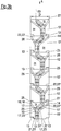
- Fig. 2 shows a perspective view of a mixing element 11 of the static mixer 2.
- the mixing element 11 is composed of six mixing segments 12.
- the six mixing segments 12 are arranged in series one after another along the longitudinal axis A of the static mixer 2.
- Each mixing segment 12 comprises four elongate inlets 13 and four elongate outlets 14.
- the elongate outlets 14 of one mixing segment 12 are arranged next to the elongate inlets 13 of the next mixing segment 12 of the series.
- each two types of mixing segments 12 are provided that each have a very similar design.
- the respective elongate inlet 13 present at the outer side 19 of the first mixing segment leads to the left hand inner elongate outlet 14 and the elongate inlet 13 present at the outer side 19" leads to the right hand inner elongate inlet 14 of the mixing segment 12.
- the respective elongate inlet 13 present at the outer side 19 of the first mixing segment leads to the right hand inner elongate outlet 14 and the elongate inlet 13 present at the outer side 19" leads to the left hand inner elongate inlet 14 of the mixing segment 12.
- the inner elongate inlet 13 closest to the side 19 of the first mixing segment 12 leads to the elongate outlet 14 present at the outer side 19''' whereas the inner elongate inlet 13 closest to the side 19" of the first mixing segment 12 leads to the elongate outlet 14 present at the outer side 19' and the inner elongate inlet 13 closest to the side 19 of the second mixing segment 12 leads to the elongate outlet 14 present at the outer side 19' whereas the inner elongate inlet 13 closest to the side 19" of the second mixing segment 12 leads to the elongate outlet 14 present at the outer side 19'''.
- the difference between the configuration and arrangement of the first and second types of mixing segments 12 of the mixing element 11 is that the elongate outlets 14 of each second type of mixing segment 12 are rotated by 180° relative to the elongate outlets 14 of the first type of mixing segment 12 and the respective second type of mixing segment is then mirror imaged at a plane comprising the longitudinal axis A and the normal thereto extending from the side19 of the drawing of Fig 2 .
- mixing segments will be discussed in the following. It should be noted that the design of every second mixing segment 12 in the series of mixing segments is identical. The use of two types of mixing segments 12 that are of similar design ensures an improved mixing of the multi-component materials M, M' by way of the corresponding mixing element 11.
- the elongate inlets 13 of the six mixing segments 12 are arranged in parallel to one another.
- the elongate outlets 14 of the six mixing segments 12 are arranged in parallel to one another.
- slight deviations from a parallel arrangement are possible, for example, deviations by ⁇ 5° to 10° are possible.
- a respective elongate inlet 13 of one mixing segment 12 is connected to a respective elongate outlet 14 of the same mixing segment 12 via a respective passage 15 to deflect respective part flows of the multi-component material from said elongate inlet 13 to said elongate outlet 14.
- the elongate outlets 14 are arranged such that an elongate extent thereof is rotated by an angle of rotation of 90° about the longitudinal axis A with respect to an elongate extent of the elongate inlets 13.
- the longitudinal axis A extends from the elongate inlets 13 to the elongate outlets 14.
- slight deviations from an arrangement at exactly 90° are possible, for example, deviations by ⁇ 5° are possible.
- a double headed arrow indicates a first extent I of the respective passage 15 in a direction in parallel to the elongate extent of the elongate inlet 13.
- the first extent I gradually reduces in size between the elongate inlet 13 and a constriction 16 of the passage 15.
- a second double headed arrow indicates a second extent O of the respective passage 15 in a direction in parallel to the elongate extent of the elongate outlet 14.
- the second extent O gradually increases in size between the constriction 16 and the elongate outlet 14.
- constriction 16 can be considered as a single point like transition between the first and second extents I, O in a plane extending in parallel to the elongate inlets 13 and elongate outlets 14 in which plane the first and second extents I, O have their respective smallest size.
- constriction 16 can be configured as an overlap region in which both the first extent I and the second extent O respectively change in size in order to reduce and expand the respective part flows of materials M, M' in the different directions corresponding to the elongate extents of the respective elongate inlets 13 and elongate outlets 14.
- the gradual change in size of the first and second extents I, O of the respective passage 15 is formed by two walls 17 of the respective passage 15 that are inclined with respect to one another and with respect to the longitudinal axis A of the mixing segment 12. Moreover, the two walls 17 inclined with respect to one another are arranged opposite one another in order to directly face one another.
- constriction 16 is formed by walls that extend in parallel to the first and second extents I, O rather than the inclined walls 17 shown in the Figures.
- change in size of the respective passage 15 is not gradual, but rather step like.
- the first extent I and the second extent O are rotated by the same angle of rotation about the longitudinal axis A as is present between each respective elongate extent of the inlet 13 and elongate extent of the elongate outlet 14.
- a transition 18 can further be seen in each passage 15 which is present between walls 17 of the passages 15 directly adjacent to further walls 21, 22 (see also Figs. 3a to 3d in this regard).
- the transition 18 can be formed by a curved part surface 18' or as a recess (not shown). It has namely been found that the provision of a curved part surface 18' or a recess as a transition has beneficial effects on mixing and guiding the part flows of multi-component material M, M' between the respective elongate inlets 13 and elongate outlets 14.
- an imaginary sleeve enveloping each mixing segment 12 at least generally has the shape of a cuboid.
- each mixing segment 12 and hence the mixing element 11 has four sides 19, 19', 19", 19"', as well as a top and a bottom side 27, 27'.
- Figs. 3a to 3d show respective views of the four sides 19, 19', 19", 19''' of the mixing element 11 of Fig. 2 .
- the walls 17 comprise curved part surfaces 17' forming guide walls that are configured to direct the part flows of the multi-component material M, M' from the respective elongate inlet 13 via the respective constriction 16 to the respective elongate outlet 14 of the respective mixing segment 12.
- each passage 15 leads to a distribution of flow components being present in each part flow of the multi-component material M, M' along the length of each of the six mixing segments 12 of the mixing element 11.
- One of these components is a flow component that flows faster through the respective passage than others.
- An outer flow component 20 is indicated in Figs. 3a to 3d that comprises flow components flowing in a direction directed at least substantially in the direction of the longitudinal axis A of the static mixer 2.
- the mixing segments 12 shown in Fig. 2 and the following are generally rectangular cuboids in which the height to side length ratios of the sides 19, 19', 19", 19''' can be selected in the range of 0.7 to 0.9, i.e. for a mixing segment of 8 mm width the height in the longitudinal direction A can be 6.4 mm.
- Figs. 3a to 3d respectively indicate the outer flow component 20 for each of the part flows present at an outer side of the mixing element 11 by means of a dashed line.
- the outer flow component 20 is one of the faster flowing components present in each mixing segment 12.
- the respective outer flow component 20 extends essentially along the inner wall of the housing 7 at the outer side 19, 19', 19", 19''' of the mixing element 11 and is less likely to be subjected to the mixing than the flow components extending through passages 15 present within other parts of the mixing segment 12.
- Faster flowing components are also present in the other passages 15 of the same mixing segment 12. This distribution of flow components arises due to the geometry of the respective mixing segment 12. The faster flowing components exit the respective elongate outlet 14 at an earlier point in time and thus arrive at the adjoining elongate inlets 13 faster than the slower flowing components. Since the static mixer is initially filled with air it can occur that air bubbles are trapped between faster flowing components and the slower flowing components arriving at the same elongate inlet 13 at a later point in time. These air bubbles can lead to the mixing result being less than ideal.
- the respective passages 15 comprise a deflector plate 26 arranged in the flow path either in the region of the elongate inlet 13 or in the region of the elongate outlet 14.
- the deflector plate 26 is configured to deflect at least some of said outer flow component 20 of the part flow of the multi-component material M, M' in the region of the elongate inlet 13 or in the region of the elongate outlet 14 away from the direction of flow directed at least substantially in the direction of the longitudinal axis A in order to further improve the mixing results.
- the deflector plate 26 is namely arranged within the respective passage 15 in order to ensure that each part flow of the multi-component material M, M' arrives at a respective elongate outlet 14 at approximately the same time, at approximately the same speed and with approximately the same surface area.
- each part flow comprises flow components that flow faster than others.
- the deflector plates 26 are configured and arranged to slow down the faster flow components such that they have approximately the same flow speed as the slower flow components in such a way that each respective part flow present in the respective passage 15 has a leading edge that extends at least approximately over the complete extent of the elongate outlet 14 and in parallel to the elongate outlet 14.
- the outer flow component 20 of the part flow of the multi-component material M, M' is slowed down by the provision of the deflector plate 26. This is indicated in the respective Figures 3a to 3d where the dashed line is led away from a central flow path. The central flow path would be present if the deflector plates 26 were not present in the respective passage 15.
- each mixing segment 12 of the mixing element 11' two deflector plates 26 in the region of its elongate inlets 13 and two-deflector plates 26 in the region of its elongate outlets 14.
- each mixing segment 12 projects from the body 24 of the mixing segment 12.
- an outer boundary of each elongate inlet 13 and elongate outlet 14 present at an outer side 19, 19', 19", 19''' of the mixing segment 12 is formed by an internal wall (not shown) of the housing 7 of the static mixer 2.
- a thickness of each of the walls 21, 22 can be selected in the range of 0.12 to 1.5 mm, especially of 0.16 to 1.05 mm. In the examples shown in Figs. 3a to 3d the walls 21, 22 have a thickness that corresponds to 0.52 mm.
- the walls 21, 22 have a height that projects from the body with said height being able to be selected in the range of 0.4 to 3 mm. In the examples shown in Figs. 3a to 3d the walls 21, 22 have a height that corresponds to 0.8 mm.
- each of the sides 19, 19', 19", 19''' of the mixing segments 12 can have a width in the direction perpendicular to the longitudinal axis A selected in the range of 4 to 15 mm and in the example shown in Figs. 3a to 3d have a width that corresponds to 8 mm.
- a wall thickness of each of the walls 21, 22 is selected to be 3 to 10%, preferably of 4 to 7% of the width of the sides 19, 19', 19", 19'''.
- each of the sides 19, 19', 19", 19''' can have a height in the direction in parallel to the longitudinal axis A selected in the range of 4 to 15 mm and in the example shown in Figs. 3a to 3d have a height that corresponds to 8 mm.
- the walls 17 forming the walls 17 inclined with respect to the longitudinal axis A respectively comprise a curved part surface 17'.
- the curved part surface 17' extends towards the constriction 16 and hence is present in the region of the constriction 16.
- the walls 17 inclined with respect to the longitudinal axis A extend from the outer sides 19, 19', 19", 19''' towards the longitudinal axis A as straight part surfaces until they reach the transition 23 formed by the curved part surface 17' that then leads to the planar surfaces 21', 22' formed by the respective walls 21, 22.
- the radii of curvature of the curved part surface 17' can generally be selected in the range of 0.2 to 0.3 times the width of the mixing segment 12, i.e. for an 8 mm wide mixing segment 12 the radii is selected in the range of 1.6 to 2.4 mm and in the examples of Figs. 3a to 3d have a radius of curvature corresponding to at least approximately 2 mm.
- the curved part surface 17' is formed by a plurality of curved part surfaces 17' each having different radii of curvature.
- the curved part surface 17' having the largest radius of curvature is that curved part surface 17' that is present within the respective constriction 16 and forms a transition 23 from the inclined wall 17 to a surface 21', 22' that extends at least substantially in parallel to the longitudinal axis A.
- the surfaces 21', 22' form part of one of walls 21, 22 of the respective elongate inlets and outlets 13, 14.
- the walls 17 of the respective passage 15 inclined with respect to the longitudinal axis A can comprise at least two gradients if formed by respective straight part surfaces.
- the straight part surfaces then extend between one of the sides 19, 19', 19", 19''' to the curved part surface 17'.
- each of the gradients is selected in the range of 0.176 to 0.577, especially of 0.2 to 0.4.
- the gradient of the straight part surface of the wall 17 is defined as the change in height in the longitudinal direction A divided by the change in width of the respective side 19, 19', 19", 19"' of the respective wall 17 and consequently is a dimensionless number.
- the walls 21, 22 forming at least a part of one of the elongate outlets 14 and/or one of the elongate inlets 13 of the mixing segment 12 respectively project from a body 24 of the mixing segment 12.
- the walls 22 projecting from the body 24 and forming at least part of the elongate outlets 14 are arranged perpendicular to the walls 21 projecting from the body 24 that form at least part of the elongate inlets 13.
- Some of the walls 21, 22 respectively projecting from the body 24 of the mixing segment 12 are connected to one another via a further wall 21", 22" at an outer side 19, 19', 19", 19''' of the mixing segments.
- some of the elongate inlets and outlets have three walls 21, 21", 22, 22" extending from the body 24.
- the further wall 21", 22" bridging the walls 21, 22 forming the respective planar surface 21', 22' each have a reduced wall thickness in comparison to the other walls 21, 22 of the same elongate inlet or outlet 13, 14.
- the walls 21", 22" bridging the walls 21, 22 are a part of the respective passage 15.
- a cut-out 25 is respectively present in the region of the elongate inlets and outlets 13, 14 arranged at each of the outer sides 19, 19', 19", 19''' of the mixing segment 12.
- the cut-out 25 is respectively provided in order to simplify a mold (not shown) that is used during the injection molding process used to manufacture the mixing element 11.
- cut-out 25 is present between the bodies 24 of directly adjacent mixing segments and the walls 21, 22 projecting from said bodies 24.
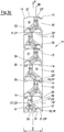
- Fig. 4 shows a perspective view of a further mixing element 11' that can be inserted into the housing 7 of the static mixer 2.
- each mixing segment 12' has four elongate inlets 13 and four elongate outlets 14.
- the respective deflector plate 26' is arranged to extend from one of the walls 21, 22 of the respective passage 15 of the directly adjacent mixing segment 12'. This is achieved by integrally forming the deflector plate 26' with said wall 21, 22 of the passage 15 of the adjacent mixing segment 12'.
- each deflector plate 26' is arranged to extend from one of the walls 21, 22 forming at least a part of the constriction 16 of an adjacent mixing segment 12'.
- the deflector plate 26' arranged in the region of the elongate inlet 13 of one mixing segment 12' is connected to one of the walls 22 of one of the directly adjacent elongate outlets 14.
- the deflector plate 26' arranged in the region of the elongate outlet 14 of one mixing segment 12 is connected to one of the walls 21 of one of the directly adjacent elongate inlets 13 of the next mixing segment 12.
- the deflector plates 26' By connecting the respective deflector plate 26' to one of the walls 21, 22 of the directly adjacent mixing segment 12, the deflector plates 26' can be formed more stable than if they were not connected to the wall 21, 22. In this way the mixing element 11' can be used particularly well for highly viscous fluids.
- the respective deflector plates 26, 26' are arranged inclined with respect to the longitudinal axis A in the region of the elongate inlet 13 and/or in the region of the elongate outlet 14 in order to deflect the outer flow component 20 away from the longitudinal axis A and to thereby improve the through mixing of the multi-component material M, M'.
- the angle of inclination of the respective deflector plate with regard to the longitudinal axis A is selected in the range of 15 to 70° and preferably as shown in Figs. 2 to 3d corresponds to 40° and in the embodiment shown in Fig. 4 corresponds to 65°.
- a length of the at least one deflector plate 26, 26' is preferably selected in the range of 20 to 70 % of the height of one of the mixing segments 12 along the longitudinal axis A of the static mixer 2.
- the deflector plate 26' has a length that corresponds to 2.8 mm.
- the deflector plate 26 has a length that corresponds to 2.6 mm.
- a width of the at least one deflector plate 26, 26' is preferably selected in the range of 2 to 10% of the width of the mixing segment 12, preferably within the range of 4 to 7% of the width of the mixing segment 12.
- the deflector plates 26, 26' are arranged such that at least one end thereof is arranged such that it is in axial alignment with a center of the constriction 16 arranged closest thereto.
- both ends of the deflector plate 26 are arranged such that they are in axial alignment with the center of the respective constriction 16 to which they are arranged closest.
- the elongate inlets 13 and the elongate outlets 14 are arranged transverse to the longitudinal axis A. It should further be noted that in accordance with all of the depicted embodiments, all of the elongate inlets 13 and of the elongate outlets 14 are configured and arranged to deflect respective part flows of the multi-component material M, M' from an elongate inlet 13 arranged at an inner region of the mixing element 11 of the static mixer 2 to an elongate outlet 14 arranged at an outer region of the mixing element 11 of the static mixer 2 and from an elongate inlet 13 arranged at the outer region of the mixing element 11 of the static mixer 2 to an elongate outlet 14 arranged at an inner region of the mixing element 11 of the static mixer 2.
- each elongate inlet 13 and each elongate outlet 14 shown in the foregoing has an opening having an at least generally rectangular shape.
- the respective mixing segments 12, 12' are formed in an injection molding process from a plastic material. Regardless of the method of manufacture of the mixing element 11, 11' respectively of the mixing segments 12, 12' the only space available within each of the mixing segments 12, 12' is part of a respective flow path for the multi-component material M, M' introduced into the static mixer 2 from the multi-component cartridge 3, 3' discussed in the foregoing.
- the volume of the multi-component materials M, M' remaining in the static mixer 2 after a dispensing process has taken place can be minimized as the dead space within the static mixers 2 are minimized in comparison to those available in the prior art.
- the specific designs of the mixing segments 12, 12' have been chosen to bring about an optimized mixing of the multi-component materials M, M'.
- the mixing element 11, 11' may also comprise other forms of mixing segments differing in design to the ones shown in the present application.
- wave like mixing segments, round mixing segments, rectangular mixing segments, mixing segments of static mixers sold under the trade name T-mixer or Quadro-mixer by Sulzer Mixpac can be used in combination with the mixing segments 12, 12' discussed in the foregoing to form the mixing element 11, 11".
- mixing segments 11, 11' described in the foregoing have a square cross-section perpendicular to the longitudinal axis A
- other kinds of cross-sections can be envisaged, e.g. rectangular, oval, round, square with rounded off edges or rectangular with rounded off edges etc.
- the walls 21, 22 of the passages 15 separating the respective elongate inlets 13 and/or elongate outlets 14 at a side of the mixing segment 12, 12" have a convex shape in the direction of the longitudinal axis A.
- Such convex shapes enable a more simple tool to be used for the injection mold and hence facilitate the manufacture of the mixing segments 12, 12" respectively of the corresponding mixing element 11'.
Landscapes
- Chemical & Material Sciences (AREA)
- Chemical Kinetics & Catalysis (AREA)
- Dispersion Chemistry (AREA)
- Processing And Handling Of Plastics And Other Materials For Molding In General (AREA)
Abstract
The present invention relates to a static mixer comprising a plurality of mixing segments for mixing a multi-component material. The static mixer (2) comprises:
a plurality of mixing segments (12, 12') arranged in series one after another along a longitudinal axis (A) of the static mixer (2); wherein at least some of the plurality of mixing segments (12, 12') comprise at least three elongate inlets (13) arranged at least substantially in parallel to one another and at least three elongate outlets (14) arranged at least substantially in parallel to one another, with a respective elongate inlet (13) being connected to a respective elongate outlet (14) via a respective passage (15), wherein the elongate outlets (14) are arranged such that an elongate extent thereof is rotated by an angle of rotation of at least 45°, preferably of at least substantially 90°, about the longitudinal axis (A) with respect to an elongate extent of the elongate inlets (13); wherein the elongate outlets (14) of one mixing segment (12, 12') are arranged next to the elongate inlets (13) of the next mixing segment (12, 12') of the series; wherein the respective passages (15) are configured to form flow paths that direct a part flow of the multi-component material (M, M') from the elongate inlet (13) to the elongate outlet (14) of the mixing segment (12, 12'); and wherein at least some of the passages (15) of the mixing segment (12, 12') comprise at least one deflector plate (26, 26') arranged in the flow path, preferably in a central part of said passage (15), in a region of the elongate inlet (13) and/or in a region of the elongate outlet (14).
a plurality of mixing segments (12, 12') arranged in series one after another along a longitudinal axis (A) of the static mixer (2); wherein at least some of the plurality of mixing segments (12, 12') comprise at least three elongate inlets (13) arranged at least substantially in parallel to one another and at least three elongate outlets (14) arranged at least substantially in parallel to one another, with a respective elongate inlet (13) being connected to a respective elongate outlet (14) via a respective passage (15), wherein the elongate outlets (14) are arranged such that an elongate extent thereof is rotated by an angle of rotation of at least 45°, preferably of at least substantially 90°, about the longitudinal axis (A) with respect to an elongate extent of the elongate inlets (13); wherein the elongate outlets (14) of one mixing segment (12, 12') are arranged next to the elongate inlets (13) of the next mixing segment (12, 12') of the series; wherein the respective passages (15) are configured to form flow paths that direct a part flow of the multi-component material (M, M') from the elongate inlet (13) to the elongate outlet (14) of the mixing segment (12, 12'); and wherein at least some of the passages (15) of the mixing segment (12, 12') comprise at least one deflector plate (26, 26') arranged in the flow path, preferably in a central part of said passage (15), in a region of the elongate inlet (13) and/or in a region of the elongate outlet (14).
Description
- The present invention relates to a static mixer comprising a plurality of mixing segments for mixing a multi-component material. The invention further relates to a dispensing assembly comprising a static mixer and a multi-component cartridge filled with respective materials, as well as to a method of dispensing multi-component material from a dispensing assembly.
- Static mixers respectively mixing tips, as they are also known as, are used to mix multi-component material dispensed from a multi-component cartridge. Such static mixers are used in a plethora of fields of application ranging from industrial applications, such as the use of adhesives to bond structural components one to another, or as protective coatings for buildings or vehicles, to medical and dental applications, for example, to make dental molds.
- The multi-component material is, for example, a two-component adhesive comprising a filler material and a hardener. In order to obtain the best possible mixing result, e.g. an adhesive having the desired bond strength, the multi-component material has to be thoroughly mixed.
- For this purpose the static mixers comprise several mixing segments arranged one after the other that repeatedly divide and re-combine part flows of the multi-component material to thoroughly mix the multi-component material.
- On mixing the multi-component material, the material remaining in the static mixer after the dispensing process is generally discarded as it remains in the static mixer. Depending on the field of application the multi-component material can be comparatively expensive and may only be used for one application at a time. This is particularly true, for example in the dental field, where only part of the multi-component material stored in the cartridge is used for one application/patient at a time with the remaining multi-component material being stored in the multi-component cartridge for future applications. Thus, the excessive use of large volumes of multi-component material remaining in a static mixer after a single use leads to unnecessary cost.
- For this reason it is an object of the present invention to provide a static mixer that guides respective part flows of the multi-component material efficiently through individual mixing segments for a thorough mixing of the multi-component material, that enables a reduction in the amount of mixing material left behind in a static mixer and that can be produced in an as facile manner as possible.
- This object is satisfied by a static mixer having the features of claim 1.
- Such a static mixer for mixing a multi-component material comprises:
- a plurality of mixing segments arranged in series one after another along a longitudinal axis of the static mixer;
- The use of at least three elongate inlets and elongate outlets provides a plurality of part flow paths along which the multi-component material can flow and be mixed. Increasing the number of flow paths within a mixing segment leads to an improvement of the mixing results achieved, since the respective part flows of the multi-component material are divided and re-combined more frequently into different part flow paths.
- Thus, the static mixer is generally designed in order to achieve the best possible mixing results while using as small a volume of the respective material of the multi-component material as possible in order to limit the waste of multi-component material.
- The changes in direction of extent of the part flows about the angle of rotation within the respective mixing segment lead to a distribution of flow components being present in each part flow of the multi-component material. Some of these flow components flow in a direction directed at least substantially in the direction of the longitudinal axis and hence arrive faster than other flow components also present in each respective passage of the respective mixing segment at the next mixing segment, since they travel the shortest distance along the respective passage.
- In this connection it should be noted that the flows of multi-component material generally have the same speed and that the terms fast, faster, slow and slower are used in the context of the present invention to indicate part flows that arrive faster or slower at certain points within the mixing segments than other part flows. The difference in times of the part flows arriving at points within the mixing segment are due to the different path lengths present for the multi-component material within the passages of the respective mixing segment.
- The at least one deflector plate is arranged and configured to deflect the faster flowing components present in each passage in such a way that they are forced to slow down and have a speed that matches those of the initially slower flowing components. The deflector plates also aid in avoiding small fractions of possibly unmixed multi-component material from flowing through the static mixer in an unhindered manner and consequently from being dispensed and thereby leading to e.g. an adhesive not having the desired bond strength.
- This is achieved by deflecting at least some of faster flowing components away from the longitudinal axis and hence reducing the speed of at least some of the faster flowing components present in each part flow and especially that of an outer flow component flowing at the boundary between a housing of the static mixer and an outer side of the mixing segments. This reduction in speed is preferably brought about in such a manner that, on exiting each elongate outlet, all flow components present in each passage exit the respective elongate outlet at the same point in time and such that they are present at the same height within each elongate outlet.
- It should be noted that the undesirable outer flow components are generally present in a direction directed at least substantially in the direction of the longitudinal axis and that hence flow faster than other flow components also present in each respective passage. The provision of the deflector plates also aids in reducing and possibly preventing such outer flow components from being present.
- In this connection it should be noted that it is preferred if the at least one deflector plate is arranged in the passage within the flow path such that it directs at least some of the flow of multi-component material away from the direction directed in the direction of the longitudinal axis such that it slows down at least some of the faster flowing components present in each part flow of the multi-component material passing through the respective passage.
- Preferably a first extent of the respective passage in a direction in parallel to the elongate extent of the elongate inlet gradually reduces in size between the elongate inlet and a constriction of the passage and a second extent of the respective passage in a direction in parallel to the elongate extent of the elongate outlet gradually increases in size between the constriction and the elongate outlet; wherein the changes in size of the first and second extents lead to a distribution of flow components being present in the part flow of the multi-component material, wherein one of these components is an outer flow component that comprises flow components flowing in a direction directed at least substantially in the direction of the longitudinal axis of the static mixer; and
wherein the at least one deflector plate is configured to deflect at least some of said outer flow component of the part flow of the multi-component material in the region of the elongate inlet and/or in the region of the elongate outlet away from the direction of flow directed at least substantially in the direction of the longitudinal axis. - In this connection it should be noted that the mixing of material present in each flow path is further facilitated by compressing the size of the flow path in the first extent and by the subsequent increase in size of the flow path in the second extent. In this way the part flow is not only forced to compress and relax in one respective direction of flow only, but due to the deflector plate is additionally guided in a plurality of directions of flow in the respective elongate inlet and outlet to further improve the mixing result.
- Advantageously the at least one deflector plate is, preferably only, provided in a passage of the mixing segment arranged at an outer side of the mixing segment. It has hitherto been found that the passages arranged within the mixing segment do not comprise single part flows that are directed generally along the longitudinal axis that may not be mixed on the passage through the static mixer, but rather only the passage present at the outer side of the mixing segments comprise such part flows. In this way the deflector plates are arranged in those regions of the static mixer which require further improvement of the mixing to take place. Moreover, the provision of the deflector plates only at the outer sides of the respective mixing segments makes the respective static mixer more simple to manufacture, e.g. in an injection molding process.
- It is preferred if at least one of the mixing segments of the static mixer comprises two deflector plates in the region of its elongate inlets and two-deflector plates in the region of its elongate outlets. By providing a deflector plate on each of the outer elongate inlets and outlets ensures a thorough mixing in each mixing segment.
- Preferably the passages within the respective mixing segment comprise walls and the at least one deflector plate is arranged to extend from one of the walls of said passage. In this way the flow of multi-component material can be further improved and tailored to the precise application. Moreover, the stability of the respective deflector plates can be enhanced by attaching these to one of the walls of the passage, in particular if they are fixedly connected to one another and/or integrally formed.
- It should be noted in this connection that each passage can comprises a constriction between the elongate inlet and the elongate outlet, and wherein each deflector plate is arranged to extend from one of the walls forming at least a part of the constriction of an adjacent mixing segment. Arranging the deflector plate in the region of a constriction further improves the guide function of the deflector plate and hence the achievable mixing results.
- It is preferred if the deflector plate arranged in the region of the elongate inlet of one mixing segment is connected to one of the walls of one of the directly adjacent elongate outlets. In this way the guide function of the at least one deflector plate and hence the achievable mixing results can be further improved.
- It is further preferred if the deflector plate arranged in the region of the elongate outlet of one mixing segment is connected to one of the walls of one of the directly adjacent elongate inlets of the next mixing segment. In this way the guide function of the at least one deflector plate and hence the achievable mixing results can be further improved.
- Advantageously the deflector plate is integrally formed with the wall of the passage. If the static mixer is e.g. manufactured in an injection molding process the deflector plate can be formed with the mixing segment in one process. Moreover, the integral formation leads to improved material strength of the deflector plate and hence prevents an accidental snapping off of the deflector plate if a fluid having a comparatively high viscosity is directed through the static mixer.
- Preferably the change in size of at least one of the first and second extents of the passage between the elongate inlet and the constriction and/or between the constriction and the elongate outlet is either step like or gradual. The deflector plate can thus be used in a plethora of designs of static mixers.
- It is preferred if the at least one deflector plate is arranged inclined with respect to the longitudinal axis in the region of the elongate inlet and/or in the region of the elongate outlet. Arranging the at least one deflector plate such that it is inclined with respect to the longitudinal axis further improves the guide and mixing functions achievable therewith. In this connection it is preferable if the at least one deflector plate is arranged such that it is inclined in the direction of the respective elongate outlet. It is however also possible to arrange the at least one deflector plate such that it is inclined in the direction of the respective elongate inlet.
- Preferably a length of the at least one deflector plate amounts to 20 to 70 % of a length of one of the mixing segments along the longitudinal axis of the static mixer. Such lengths have been found desirable to achieve improved mixing results.
- Advantageously the static mixer further comprises a housing accommodating said plurality of mixing segments, an outlet for dispensing mixed multi-component material, and inlets that are configured to be coupled to outlets of a multi-component cartridge.
- In this connection it should be noted that an inner surface of the housing is complementary shaped to the outer shape of the mixing segments of the static mixer in such a way that the inner surface forms an at least substantially planar boundary of the passages present at the outer sides of the mixing segments.
- According to a further aspect the present invention further relates to a dispensing assembly. The dispensing assembly comprises:
- a static mixer as discussed herein,
- the multi-component cartridge filled with multi-component material; and/or
- a dispensing device that can be actuated to dispense said multi-component material via said static mixer.
- The advantages discussed in the foregoing in relation to the static mixer likewise hold true for the dispensing assembly in accordance with the invention.
- The multi-component cartridge can thus be filled with materials selected from the group of members consisting of topical medications, medical fluids, wound care fluids, cosmetic and/or skin care preparations, dental fluids, veterinary fluids, adhesive fluids, disinfectant fluids, protective fluids, paints and combinations of the foregoing.
- Such fluids and hence the dispensing assembly can therefore be expediently used in the treatment of target areas such as the nose (e.g. anti-histaminic creams etc.), ears, teeth (e.g. molds for implants or buccal applications (e.g. aphtas, gum treatment, mouth sores etc.), eyes (e.g. the precise deposition of drugs on eyelids (e.g. chalazion, infection, anti-inflammatory, antibiotics etc.), lips (e.g. herpes), mouth, skin (e.g. anti-fungal, dark spot, acne, warts, psoriasis, skin cancer treatment, tattoo removal drugs, wound healing, scar treatment, stain removal, anti-itch applications etc.), other dermatological applications (e.g. skin nails (for example anti-fungal applications, or strengthening formulas etc.) or cytological applications.
- Alternatively the fluids and hence the dispensing assembly can also be used in an industrial sector, e.g. in the building industry, the automotive industry etc., for example, as adhesives, paints, and/or as protective coatings.
- According to a further aspect the present invention further relates to a method of dispensing multi-component material from a dispensing assembly in accordance with the teaching presented herein. The method comprises the step of:
- actuating the dispensing device to urge the multi-component material stored in said multi-component cartridge into the static mixer and mixing the multi-component material in said static mixer, wherein at least some of one of the part flows of the multi-component material mixed in said static mixer is deflected away from the longitudinal axis by means of the at least one deflector plate.
- Further embodiments of the invention are described in the following description of the Figures. The invention will be explained in the following in detail by means of embodiments and with reference to the drawing in which is shown:
- Fig. 1
- a perspective view of a dispensing assembly;
- Fig. 2
- a perspective view of a mixing element of a static mixer;
- Figs. 3a to 3d
- respective side views of the mixing element of
Fig. 2 ; and - Fig. 4
- a perspective view of a further mixing element.
- In the following the same reference numerals will be used for parts having the same or equivalent function. Any statements made having regard to the direction of a component are made relative to the position shown in the drawing and can naturally vary in the actual position of application.
-
Fig. 1 schematically shows a dispensing assembly 1 comprising astatic mixer 2 and a multi-component cartridge 3. The multi-component cartridge 3 shown inFig. 1 is a two-component cartridge 3' that is filled with respective two-component materials M, M', for example, a hardener and a binder material. - The
static mixer 2 comprises twoinlets 4, 4' at afirst end 5 thereof. The twoinlets 4, 4' connect tooutlets 6, 6' of the two-component cartridge 3'. In the present example theinlets 4, 4' receive theoutlets 6, 6' of the two-component cartridge 3'. It should be noted in this connection that other forms of interaction between theinlets 4, 4' and theoutlets 6, 6' are possible. - A
housing 7 of the schematically illustratedstatic mixer 2 further comprises alignment means 8, 8' that enable a correct alignment of theinlets 4, 4' of thestatic mixer 2 relative to theoutlets 6, 6' of the two-component cartridge 3'. The alignment means 8, 8' can for example be configured as bayonet-like connection means (not shown) and hence also act as a kind of attachment means (not shown) to attach thestatic mixer 2 to the two-component cartridge 3'. Other kind of attachment means (also not shown) such as a locking ring can also be used and are well known to the person skilled in the art. - The
housing 7 further has a dispensingoutlet 9 at asecond end 10 of thestatic mixer 2. The mixed multi-component material M, M' is dispensed via the dispensingoutlet 9 following its passage through thestatic mixer 2. The dispensingoutlet 9 is arranged at a longitudinal axis A of thestatic mixer 2. The longitudinal axis A extends from theinlets 4, 4' of thestatic mixer 2 to the dispensingoutlet 9 of thestatic mixer 2. -
Fig. 2 shows a perspective view of a mixingelement 11 of thestatic mixer 2. The mixingelement 11 is composed of six mixingsegments 12. The sixmixing segments 12 are arranged in series one after another along the longitudinal axis A of thestatic mixer 2. Each mixingsegment 12 comprises fourelongate inlets 13 and fourelongate outlets 14. Theelongate outlets 14 of onemixing segment 12 are arranged next to theelongate inlets 13 of thenext mixing segment 12 of the series. - In the present example each two types of mixing
segments 12 are provided that each have a very similar design. The difference being that the respectiveelongate inlet 13 present at theouter side 19 of the first mixing segment leads to the left hand innerelongate outlet 14 and theelongate inlet 13 present at theouter side 19" leads to the right hand innerelongate inlet 14 of the mixingsegment 12. With regard to thesecond mixing segment 12 of the series the respectiveelongate inlet 13 present at theouter side 19 of the first mixing segment leads to the right hand innerelongate outlet 14 and theelongate inlet 13 present at theouter side 19" leads to the left hand innerelongate inlet 14 of the mixingsegment 12. - In the same way the inner
elongate inlet 13 closest to theside 19 of thefirst mixing segment 12 leads to theelongate outlet 14 present at the outer side 19''' whereas the innerelongate inlet 13 closest to theside 19" of thefirst mixing segment 12 leads to theelongate outlet 14 present at the outer side 19' and the innerelongate inlet 13 closest to theside 19 of thesecond mixing segment 12 leads to theelongate outlet 14 present at the outer side 19' whereas the innerelongate inlet 13 closest to theside 19" of thesecond mixing segment 12 leads to theelongate outlet 14 present at the outer side 19'''. - In this connection the difference between the configuration and arrangement of the first and second types of mixing
segments 12 of the mixingelement 11 is that theelongate outlets 14 of each second type of mixingsegment 12 are rotated by 180° relative to theelongate outlets 14 of the first type of mixingsegment 12 and the respective second type of mixing segment is then mirror imaged at a plane comprising the longitudinal axis A and the normal thereto extending from the side19 of the drawing ofFig 2 . - The design of the mixing segments will be discussed in the following. It should be noted that the design of every
second mixing segment 12 in the series of mixing segments is identical. The use of two types of mixingsegments 12 that are of similar design ensures an improved mixing of the multi-component materials M, M' by way of the corresponding mixingelement 11. - The
elongate inlets 13 of the six mixingsegments 12 are arranged in parallel to one another. Likewise theelongate outlets 14 of the six mixingsegments 12 are arranged in parallel to one another. In this connection it should be noted that slight deviations from a parallel arrangement are possible, for example, deviations by ± 5° to 10° are possible. - A respective
elongate inlet 13 of onemixing segment 12 is connected to a respectiveelongate outlet 14 of thesame mixing segment 12 via arespective passage 15 to deflect respective part flows of the multi-component material from saidelongate inlet 13 to saidelongate outlet 14. - The
elongate outlets 14 are arranged such that an elongate extent thereof is rotated by an angle of rotation of 90° about the longitudinal axis A with respect to an elongate extent of theelongate inlets 13. In this connection it should be noted that the longitudinal axis A extends from theelongate inlets 13 to theelongate outlets 14. In this connection it should be noted that slight deviations from an arrangement at exactly 90° are possible, for example, deviations by ± 5° are possible. - A double headed arrow indicates a first extent I of the
respective passage 15 in a direction in parallel to the elongate extent of theelongate inlet 13. The first extent I gradually reduces in size between theelongate inlet 13 and aconstriction 16 of thepassage 15. A second double headed arrow indicates a second extent O of therespective passage 15 in a direction in parallel to the elongate extent of theelongate outlet 14. The second extent O gradually increases in size between theconstriction 16 and theelongate outlet 14. - In this connection it should be noted that the
constriction 16 can be considered as a single point like transition between the first and second extents I, O in a plane extending in parallel to theelongate inlets 13 andelongate outlets 14 in which plane the first and second extents I, O have their respective smallest size. - Alternatively the
constriction 16 can be configured as an overlap region in which both the first extent I and the second extent O respectively change in size in order to reduce and expand the respective part flows of materials M, M' in the different directions corresponding to the elongate extents of the respectiveelongate inlets 13 andelongate outlets 14. - The gradual change in size of the first and second extents I, O of the
respective passage 15 is formed by twowalls 17 of therespective passage 15 that are inclined with respect to one another and with respect to the longitudinal axis A of the mixingsegment 12. Moreover, the twowalls 17 inclined with respect to one another are arranged opposite one another in order to directly face one another. - In this connection it can also be conceived that the
constriction 16 is formed by walls that extend in parallel to the first and second extents I, O rather than theinclined walls 17 shown in the Figures. In this case the change in size of therespective passage 15 is not gradual, but rather step like. - When multi-component material M, M' is guided in the
respective passage 15, the material M, M' present in each flow path is urged together between the respectiveelongate inlet 13 and therespective constriction 16 in the first extent I decreasing towards therespective constriction 16. Subsequently the material M, M' present in each flow path is permitted to relax by the subsequent increase in size of the flow path in the direction of the second extent O. This constriction and expansion of the multi-component materials M, M' takes place in different directions relative to the longitudinal axis A to improve the through mixing of the multi-component materials M, M'. - The first extent I and the second extent O are rotated by the same angle of rotation about the longitudinal axis A as is present between each respective elongate extent of the
inlet 13 and elongate extent of theelongate outlet 14. - A transition 18 can further be seen in each
passage 15 which is present betweenwalls 17 of thepassages 15 directly adjacent to furtherwalls 21, 22 (see alsoFigs. 3a to 3d in this regard). The transition 18 can be formed by a curved part surface 18' or as a recess (not shown). It has namely been found that the provision of a curved part surface 18' or a recess as a transition has beneficial effects on mixing and guiding the part flows of multi-component material M, M' between the respectiveelongate inlets 13 andelongate outlets 14. - It should further be noted that an imaginary sleeve enveloping each mixing
segment 12 at least generally has the shape of a cuboid. In this way each mixingsegment 12 and hence the mixingelement 11 has foursides bottom side 27, 27'. -
Figs. 3a to 3d show respective views of the foursides element 11 ofFig. 2 . Thewalls 17 comprise curved part surfaces 17' forming guide walls that are configured to direct the part flows of the multi-component material M, M' from the respectiveelongate inlet 13 via therespective constriction 16 to the respectiveelongate outlet 14 of therespective mixing segment 12. - The changes in size of each
passage 15 lead to a distribution of flow components being present in each part flow of the multi-component material M, M' along the length of each of the six mixingsegments 12 of the mixingelement 11. One of these components is a flow component that flows faster through the respective passage than others. Anouter flow component 20 is indicated inFigs. 3a to 3d that comprises flow components flowing in a direction directed at least substantially in the direction of the longitudinal axis A of thestatic mixer 2. - In this connection it should be noted that the mixing
segments 12 shown inFig. 2 and the following are generally rectangular cuboids in which the height to side length ratios of thesides -
Figs. 3a to 3d respectively indicate theouter flow component 20 for each of the part flows present at an outer side of the mixingelement 11 by means of a dashed line. Theouter flow component 20 is one of the faster flowing components present in each mixingsegment 12. The respectiveouter flow component 20 extends essentially along the inner wall of thehousing 7 at theouter side element 11 and is less likely to be subjected to the mixing than the flow components extending throughpassages 15 present within other parts of the mixingsegment 12. - Faster flowing components are also present in the
other passages 15 of thesame mixing segment 12. This distribution of flow components arises due to the geometry of therespective mixing segment 12. The faster flowing components exit the respectiveelongate outlet 14 at an earlier point in time and thus arrive at the adjoiningelongate inlets 13 faster than the slower flowing components. Since the static mixer is initially filled with air it can occur that air bubbles are trapped between faster flowing components and the slower flowing components arriving at the sameelongate inlet 13 at a later point in time. These air bubbles can lead to the mixing result being less than ideal. - In order to prevent small fractions of unmixed multi-component material M, M' e.g. the
outer flow component 20 from flowing between theinlets 4, 4' and theoutlet 9 of thestatic mixer 2 and to prevent such air bubbles from arising and consequently from non-ideal mixing results from being dispensed, therespective passages 15 comprise adeflector plate 26 arranged in the flow path either in the region of theelongate inlet 13 or in the region of theelongate outlet 14. - The
deflector plate 26 is configured to deflect at least some of saidouter flow component 20 of the part flow of the multi-component material M, M' in the region of theelongate inlet 13 or in the region of theelongate outlet 14 away from the direction of flow directed at least substantially in the direction of the longitudinal axis A in order to further improve the mixing results. - The
deflector plate 26 is namely arranged within therespective passage 15 in order to ensure that each part flow of the multi-component material M, M' arrives at a respectiveelongate outlet 14 at approximately the same time, at approximately the same speed and with approximately the same surface area. - Due to the varying geometries present within the
respective passage 15 of the mixingsegment 12 each part flow comprises flow components that flow faster than others. Thedeflector plates 26 are configured and arranged to slow down the faster flow components such that they have approximately the same flow speed as the slower flow components in such a way that each respective part flow present in therespective passage 15 has a leading edge that extends at least approximately over the complete extent of theelongate outlet 14 and in parallel to theelongate outlet 14. Thus, in particular theouter flow component 20 of the part flow of the multi-component material M, M' is slowed down by the provision of thedeflector plate 26. This is indicated in the respectiveFigures 3a to 3d where the dashed line is led away from a central flow path. The central flow path would be present if thedeflector plates 26 were not present in therespective passage 15. - It should be noted that the
deflector plates 26 are arranged at theouter sides segments 12. As is visible from the views shown inFigs. 3a to 3d each mixingsegment 12 of the mixing element 11' twodeflector plates 26 in the region of itselongate inlets 13 and two-deflector plates 26 in the region of itselongate outlets 14. - The
walls elongate inlets 13 andoutlets 14 of each mixingsegment 12 project from thebody 24 of the mixingsegment 12. In this connection it should be noted that an outer boundary of eachelongate inlet 13 andelongate outlet 14 present at anouter side segment 12 is formed by an internal wall (not shown) of thehousing 7 of thestatic mixer 2. - It should further be noted that a thickness of each of the
walls Figs. 3a to 3d thewalls - It should further be noted that the
walls Figs. 3a to 3d thewalls - In this connection it should be noted that each of the
sides segments 12 can have a width in the direction perpendicular to the longitudinal axis A selected in the range of 4 to 15 mm and in the example shown inFigs. 3a to 3d have a width that corresponds to 8 mm. - Preferably a wall thickness of each of the
walls sides - In this connection it should be noted that each of the
sides Figs. 3a to 3d have a height that corresponds to 8 mm. - As indicated in
Figs. 3a to 3d thewalls 17 forming thewalls 17 inclined with respect to the longitudinal axis A respectively comprise a curved part surface 17'. The curved part surface 17' extends towards theconstriction 16 and hence is present in the region of theconstriction 16. - The
walls 17 inclined with respect to the longitudinal axis A extend from theouter sides transition 23 formed by the curved part surface 17' that then leads to the planar surfaces 21', 22' formed by therespective walls - In this connection it should be noted that the radii of curvature of the curved part surface 17' can generally be selected in the range of 0.2 to 0.3 times the width of the mixing
segment 12, i.e. for an 8 mmwide mixing segment 12 the radii is selected in the range of 1.6 to 2.4 mm and in the examples ofFigs. 3a to 3d have a radius of curvature corresponding to at least approximately 2 mm. - It is further possible that the curved part surface 17' is formed by a plurality of curved part surfaces 17' each having different radii of curvature. In this event, the curved part surface 17' having the largest radius of curvature is that curved part surface 17' that is present within the
respective constriction 16 and forms atransition 23 from theinclined wall 17 to a surface 21', 22' that extends at least substantially in parallel to the longitudinal axis A. The surfaces 21', 22' form part of one ofwalls outlets - It should be noted in this connection that the
walls 17 of therespective passage 15 inclined with respect to the longitudinal axis A can comprise at least two gradients if formed by respective straight part surfaces. The straight part surfaces then extend between one of thesides - In this connection it should be noted that each of the gradients is selected in the range of 0.176 to 0.577, especially of 0.2 to 0.4. In this connection it should be noted that the gradient of the straight part surface of the
wall 17 is defined as the change in height in the longitudinal direction A divided by the change in width of therespective side respective wall 17 and consequently is a dimensionless number. - The
walls elongate outlets 14 and/or one of theelongate inlets 13 of the mixingsegment 12 respectively project from abody 24 of the mixingsegment 12. Thewalls 22 projecting from thebody 24 and forming at least part of theelongate outlets 14 are arranged perpendicular to thewalls 21 projecting from thebody 24 that form at least part of theelongate inlets 13. - Some of the
walls body 24 of the mixingsegment 12 are connected to one another via afurther wall 21", 22" at anouter side walls body 24. Thefurther wall 21", 22" bridging thewalls other walls outlet walls 21", 22" bridging thewalls respective passage 15. - A cut-out 25 is respectively present in the region of the elongate inlets and
outlets outer sides segment 12. The cut-out 25 is respectively provided in order to simplify a mold (not shown) that is used during the injection molding process used to manufacture the mixingelement 11. - In this connection it should be noted that the cut-out 25 is present between the
bodies 24 of directly adjacent mixing segments and thewalls bodies 24. - As discussed in the foregoing, the changes in size present in each of the
passages 15 lead to a distribution of flow components being present in the part flow of the multi-component material M, M'. -
Fig. 4 shows a perspective view of a further mixing element 11' that can be inserted into thehousing 7 of thestatic mixer 2. In the design depicted inFig. 4 each mixing segment 12' has fourelongate inlets 13 and fourelongate outlets 14. The respective deflector plate 26' is arranged to extend from one of thewalls respective passage 15 of the directly adjacent mixing segment 12'. This is achieved by integrally forming the deflector plate 26' with saidwall passage 15 of the adjacent mixing segment 12'. - In fact each deflector plate 26' is arranged to extend from one of the
walls constriction 16 of an adjacent mixing segment 12'. In this way the deflector plate 26' arranged in the region of theelongate inlet 13 of one mixing segment 12' is connected to one of thewalls 22 of one of the directly adjacentelongate outlets 14. Likewise the deflector plate 26' arranged in the region of theelongate outlet 14 of onemixing segment 12 is connected to one of thewalls 21 of one of the directly adjacentelongate inlets 13 of thenext mixing segment 12. - By connecting the respective deflector plate 26' to one of the
walls adjacent mixing segment 12, the deflector plates 26' can be formed more stable than if they were not connected to thewall - The
respective deflector plates 26, 26' are arranged inclined with respect to the longitudinal axis A in the region of theelongate inlet 13 and/or in the region of theelongate outlet 14 in order to deflect theouter flow component 20 away from the longitudinal axis A and to thereby improve the through mixing of the multi-component material M, M'. In this connection it should be noted that the angle of inclination of the respective deflector plate with regard to the longitudinal axis A is selected in the range of 15 to 70° and preferably as shown inFigs. 2 to 3d corresponds to 40° and in the embodiment shown inFig. 4 corresponds to 65°. - In this connection it should be noted that a length of the at least one
deflector plate 26, 26' is preferably selected in the range of 20 to 70 % of the height of one of the mixingsegments 12 along the longitudinal axis A of thestatic mixer 2. In the embodiment depicted inFig. 4 the deflector plate 26' has a length that corresponds to 2.8 mm. Whereas in the embodiment ofFigs. 2 to 3d thedeflector plate 26 has a length that corresponds to 2.6 mm. - In this connection it should be noted that a width of the at least one
deflector plate 26, 26' is preferably selected in the range of 2 to 10% of the width of the mixingsegment 12, preferably within the range of 4 to 7% of the width of the mixingsegment 12. - Generally speaking the
deflector plates 26, 26' are arranged such that at least one end thereof is arranged such that it is in axial alignment with a center of theconstriction 16 arranged closest thereto. - In the embodiment of
Fig. 4 the end remote from the end of the deflector plate 26' projecting from thewall passage 15 of the adjacent mixing segment 12' is in axial alignment with the center of theconstriction 16 arranged closest thereto. - In the embodiment of
Figs. 2 to 3d both ends of thedeflector plate 26 are arranged such that they are in axial alignment with the center of therespective constriction 16 to which they are arranged closest. - In all of the embodiments shown the
elongate inlets 13 and theelongate outlets 14 are arranged transverse to the longitudinal axis A. It should further be noted that in accordance with all of the depicted embodiments, all of theelongate inlets 13 and of theelongate outlets 14 are configured and arranged to deflect respective part flows of the multi-component material M, M' from anelongate inlet 13 arranged at an inner region of the mixingelement 11 of thestatic mixer 2 to anelongate outlet 14 arranged at an outer region of the mixingelement 11 of thestatic mixer 2 and from anelongate inlet 13 arranged at the outer region of the mixingelement 11 of thestatic mixer 2 to anelongate outlet 14 arranged at an inner region of the mixingelement 11 of thestatic mixer 2. - It should further be noted that each
elongate inlet 13 and eachelongate outlet 14 shown in the foregoing has an opening having an at least generally rectangular shape. - It is preferred if the
respective mixing segments 12, 12' are formed in an injection molding process from a plastic material. Regardless of the method of manufacture of the mixingelement 11, 11' respectively of the mixingsegments 12, 12' the only space available within each of the mixingsegments 12, 12' is part of a respective flow path for the multi-component material M, M' introduced into thestatic mixer 2 from the multi-component cartridge 3, 3' discussed in the foregoing. - In this way the volume of the multi-component materials M, M' remaining in the
static mixer 2 after a dispensing process has taken place can be minimized as the dead space within thestatic mixers 2 are minimized in comparison to those available in the prior art. Moreover, the specific designs of the mixingsegments 12, 12' have been chosen to bring about an optimized mixing of the multi-component materials M, M'. - In this connection it should be noted that the
various mixing segments 12, 12' discussed in the foregoing to form the presented mixingelements 11, 11' can also be mixed to form a mixing element (not shown) comprising a mixture of thevarious mixing segments 12, 12' discussed and shown in the present application. - The mixing
element 11, 11' may also comprise other forms of mixing segments differing in design to the ones shown in the present application. For example, wave like mixing segments, round mixing segments, rectangular mixing segments, mixing segments of static mixers sold under the trade name T-mixer or Quadro-mixer by Sulzer Mixpac can be used in combination with the mixingsegments 12, 12' discussed in the foregoing to form the mixingelement - In this connection it should be noted that although the mixing
segments 11, 11' described in the foregoing have a square cross-section perpendicular to the longitudinal axis A, other kinds of cross-sections can be envisaged, e.g. rectangular, oval, round, square with rounded off edges or rectangular with rounded off edges etc. - As is further visible in the view of the mixing element 11', the
walls passages 15 separating the respectiveelongate inlets 13 and/orelongate outlets 14 at a side of the mixingsegment segments -
- 1
- dispensing assembly
- 2
- static mixer
- 3, 3'
- multi-component cartridge, two-component cartridge
- 4, 4'
- inlet
- 5
- first end
- 6, 6'
- outlet
- 7
- housing
- 8, 8'
- alignment means
- 9
- dispensing outlet
- 10
- second end
- 11, 11'
- mixing element
- 12, 12'
- mixing segment
- 13
- elongate inlet
- 14
- elongate outlet
- 15
- passage
- 16
- constriction
- 17, 17'
- wall, curved part surface
- 18, 18'
- transition, recess
- 19, 19', 19", 19'''
- side
- 20
- outer flow component
- 21, 21', 21"
- wall, surface, wall
- 22, 22', 22"
- wall, surface, wall
- 23
- transition
- 24
- body
- 25
- cut-out
- 26, 26'
- deflector plate
- 27, 27'
- top side, bottom side
- A
- longitudinal axis
- I
- first extent
- M, M'
- material
- O
- second extent
wherein the elongate outlets of one mixing segment are arranged next to the elongate inlets of the next mixing segment of the series;
wherein the respective passages are configured to form flow paths that direct a part flow of the multi-component material from the elongate inlet to the elongate outlet of the mixing segment; and
wherein at least some of the passages of the mixing segment comprise at least one deflector plate arranged in the flow path, preferably in a central part of said passage, in a region of the elongate inlet and/or in a region of the elongate outlet.
Claims (15)
- A static mixer (2) for mixing a multi-component material (M, M'), the static mixer (2) comprising:a plurality of mixing segments (12, 12') arranged in series one after another along a longitudinal axis (A) of the static mixer (2);wherein at least some of the plurality of mixing segments (12, 12') comprise at least three elongate inlets (13) arranged at least substantially in parallel to one another and at least three elongate outlets (14) arranged at least substantially in parallel to one another, with a respective elongate inlet (13) being connected to a respective elongate outlet (14) via a respective passage (15), wherein the elongate outlets (14) are arranged such that an elongate extent thereof is rotated by an angle of rotation of at least 45°,preferably of at least substantially 90°, about the longitudinal axis (A) with respect to an elongate extent of the elongate inlets (13);wherein the elongate outlets (14) of one mixing segment (12, 12') are arranged next to the elongate inlets (13) of the next mixing segment (12, 12') of the series;wherein the respective passages (15) are configured to form flow paths that direct a part flow of the multi-component material (M, M') from the elongate inlet (13) to the elongate outlet (14) of the mixing segment (12, 12'); andwherein at least some of the passages (15) of the mixing segment (12, 12') comprise at least one deflector plate (26, 26') arranged in the flow path,preferably in a central part of said passage (15), in a region of the elongate inlet (13) and/or in a region of the elongate outlet (14).
- A static mixer (2) in accordance with claim 1,
wherein a first extent (I) of the respective passage (15) in a direction in parallel to the elongate extent of the elongate inlet (13) gradually reduces in size between the elongate inlet (13) and a constriction (16) of the passage (15) and a second extent (O) of the respective passage (15) in a direction in parallel to the elongate extent of the elongate outlet (14) gradually increases in size between the constriction (16) and the elongate outlet (14); wherein the changes in size of the first and second extents (I, O) lead to a distribution of flow components being present in the part flow of the multi-component material (M, M'), wherein one of these components is an outer flow component (20) that comprises flow components flowing in a direction directed at least substantially in the direction of the longitudinal axis (A) of the static mixer (2); and
wherein the at least one deflector plate (26, 26') is configured to deflect at least some of said outer flow component (20) of the part flow of the multi-component material (M, M') in the region of the elongate inlet (13) and/or in the region of the elongate outlet (14) away from the direction of flow directed at least substantially in the direction of the longitudinal axis (A). - A static mixer (2) in accordance with claim 1 or claim 2,
wherein the at least one deflector plate (26, 26') is, preferably only, provided in a passage (15) of the mixing segment (12, 12') arranged at an outer side (19, 19', 19", 19''') of the mixing segment (12, 12'). - A static mixer (2) in accordance with at least one of the preceding claims,
wherein at least one of the mixing segments (12, 12') of the static mixer (2) comprises two deflector plates (26, 26') in the region of its elongate inlets (13) and two-deflector plates (26, 26') in the region of its elongate outlets (14). - A static mixer (2) in accordance with at least one of the preceding claims,
wherein the passages (15) comprise walls (17, 21, 21", 22, 22") and the at least one deflector plate (26, 26') is arranged to extend from one of the walls (17, 21, 22) of said passage (15). - A static mixer (2) in accordance with claim 5,
wherein each passage (15) comprises a constriction (16) between the elongate inlet (13) and the elongate outlet (14), and wherein each deflector plate (26') is arranged to extend from one of the walls (17, 21, 22) forming at least a part of the constriction (16) of an adjacent mixing segment (12, 12'). - A static mixer (2) in accordance with claim 5 or claim 6,
wherein the deflector plate (26') arranged in the region of the elongate inlet (13) of one mixing segment (12, 12') is connected to one of the walls (22) of one of the directly adjacent elongate outlets (14). - A static mixer (2) in accordance with claim 5 or claim 6,
wherein the deflector plate (26') arranged in the region of the elongate outlet (14) of one mixing segment (12, 12') is connected to one of the walls (21) of one of the directly adjacent elongate inlets (13) of the next mixing segment (12, 12'). - A static mixer (2) in accordance with at least one of the preceding claims 5 to 8, wherein the deflector plate (26') is integrally formed with the wall (21, 22) of the passage (15).
- A static mixer (2) in accordance with at least one of the preceding claims 2 to 9, wherein the change in size of one of the first and second extents (I, O) of the passage (15) between the elongate inlet (13) and the constriction (16) and/or between the constriction (16) and the elongate outlet (14) is either step like or gradual.
- A static mixer (2) in accordance with at least one of the preceding claims,
wherein the at least one deflector plate (26, 26') is arranged inclined with respect to the longitudinal axis (A) in the region of the elongate inlet (13) and/or in the region of the elongate outlet (14). - A static mixer (2) in accordance with at least one of the preceding claims,
wherein a length of the at least one deflector plate (26, 26') amounts to 20 to 70 % of a length of one of the mixing segments (12, 12') along the longitudinal axis (A) of the static mixer (2). - A static mixer (2) in accordance with at least one of the preceding claims, further comprising a housing (7) accommodating said plurality of mixing segments (12), an outlet (9) for dispensing mixed multi-component material (M, M'), and inlets (4, 4') that are configured to be coupled to outlets (6, 6') of a multi-component cartridge (3, 3').
- A dispensing assembly (1) comprising:- the static mixer (2) in accordance with at least one of the preceding claims,- the multi-component cartridge (3, 3') filled with multi-component material (M, M'); and/or- a dispensing device that can be actuated to dispense said multi-component material (M, M') via said static mixer (2).
- A method of dispensing multi-component material (M, M') from a dispensing assembly (1) in accordance with claim 14, the method comprising the step of:- actuating the dispensing device to urge the multi-component material (M, M') stored in said multi-component cartridge (3, 3') into the static mixer (2) and mixing the multi-component material (M, M') in said static mixer (2), wherein at least some of one of the part flows of the multi-component material (M, M') mixed in said static mixer (2) is deflected away from the longitudinal axis (A) by means of the at least one deflector plate (26, 26').
Priority Applications (3)
| Application Number | Priority Date | Filing Date | Title |
|---|---|---|---|
| EP17198862.9A EP3476467A1 (en) | 2017-10-27 | 2017-10-27 | Static mixer, dispensing assembly and method of dispensing multicomponent material |
| PCT/EP2018/079445 WO2019081727A1 (en) | 2017-10-27 | 2018-10-26 | Static mixer, dispensing assembly and method of dispensing multi-component material |
| EP18789450.6A EP3684499B1 (en) | 2017-10-27 | 2018-10-26 | Static mixer, dispensing assembly and method of dispensing multi-component material |
Applications Claiming Priority (1)
| Application Number | Priority Date | Filing Date | Title |
|---|---|---|---|
| EP17198862.9A EP3476467A1 (en) | 2017-10-27 | 2017-10-27 | Static mixer, dispensing assembly and method of dispensing multicomponent material |
Publications (1)
| Publication Number | Publication Date |
|---|---|
| EP3476467A1 true EP3476467A1 (en) | 2019-05-01 |
Family
ID=60191183
Family Applications (2)
| Application Number | Title | Priority Date | Filing Date |
|---|---|---|---|
| EP17198862.9A Withdrawn EP3476467A1 (en) | 2017-10-27 | 2017-10-27 | Static mixer, dispensing assembly and method of dispensing multicomponent material |
| EP18789450.6A Active EP3684499B1 (en) | 2017-10-27 | 2018-10-26 | Static mixer, dispensing assembly and method of dispensing multi-component material |
Family Applications After (1)
| Application Number | Title | Priority Date | Filing Date |
|---|---|---|---|
| EP18789450.6A Active EP3684499B1 (en) | 2017-10-27 | 2018-10-26 | Static mixer, dispensing assembly and method of dispensing multi-component material |
Country Status (2)
| Country | Link |
|---|---|
| EP (2) | EP3476467A1 (en) |
| WO (1) | WO2019081727A1 (en) |
Cited By (1)
| Publication number | Priority date | Publication date | Assignee | Title |
|---|---|---|---|---|
| CN115738986A (en) * | 2022-11-01 | 2023-03-07 | 南京先进生物材料与过程装备研究院有限公司 | Intensive mixing internal member and method for preparing perfluoroalkyl aniline by using same |
Families Citing this family (1)
| Publication number | Priority date | Publication date | Assignee | Title |
|---|---|---|---|---|
| DE102020006640A1 (en) * | 2020-10-29 | 2022-05-05 | Staedtler Mars Gmbh & Co. Kg | Device for applying masses and their use |
Citations (1)
| Publication number | Priority date | Publication date | Assignee | Title |
|---|---|---|---|---|
| US3195865A (en) * | 1960-09-09 | 1965-07-20 | Dow Chemical Co | Interfacial surface generator |
-
2017
- 2017-10-27 EP EP17198862.9A patent/EP3476467A1/en not_active Withdrawn
-
2018
- 2018-10-26 EP EP18789450.6A patent/EP3684499B1/en active Active
- 2018-10-26 WO PCT/EP2018/079445 patent/WO2019081727A1/en not_active Ceased
Patent Citations (1)
| Publication number | Priority date | Publication date | Assignee | Title |
|---|---|---|---|---|
| US3195865A (en) * | 1960-09-09 | 1965-07-20 | Dow Chemical Co | Interfacial surface generator |
Cited By (1)
| Publication number | Priority date | Publication date | Assignee | Title |
|---|---|---|---|---|
| CN115738986A (en) * | 2022-11-01 | 2023-03-07 | 南京先进生物材料与过程装备研究院有限公司 | Intensive mixing internal member and method for preparing perfluoroalkyl aniline by using same |
Also Published As
| Publication number | Publication date |
|---|---|
| WO2019081727A1 (en) | 2019-05-02 |
| EP3684499A1 (en) | 2020-07-29 |
| EP3684499B1 (en) | 2022-02-23 |
Similar Documents
| Publication | Publication Date | Title |
|---|---|---|
| EP3681622B1 (en) | Mixing segment, static mixer, dispensing assembly and method of mixing multi-component material | |
| CN102387871B (en) | Device for discharging filling | |
| US20200346176A1 (en) | Static mixer, dispensing assembly and method of dispensing multi-component material from a dispensing assembly | |
| EP3684499B1 (en) | Static mixer, dispensing assembly and method of dispensing multi-component material | |
| EP3106122A1 (en) | A system comprising a static mixer and a dispensing device for dental materials | |
| US20100028831A1 (en) | Dispensing syringe having multiple barrels for discharging a dental composition | |
| KR102568466B1 (en) | Static mixer, assembly method of static mixer and dispensing device | |
| EP3917657B1 (en) | Dynamic mixer, dispensing assembly and method of dispensing multi-component material from a cartridge | |
| EP3710148B1 (en) | Mixer, multi-component dispenser, and method of dispensing multi-component material from a multi-component dispenser | |
| EP3485967A1 (en) | Static mixer, dispensing assembly and method of dispensing multi-component material from a dispensing assembly | |
| WO2023222720A2 (en) | Dispensing system, dispensing outlet and cartridge | |
| EP3921071B1 (en) | Dynamic mixer, dispensing assembly and method of dispensing multi-component material from a cartridge | |
| EP3608013A1 (en) | Mixing segment, static mixer, dispensing assembly and method of mixing multi-component material | |
| EP4279185B1 (en) | Dispensing system, and dispensing outlet | |
| WO2025103934A1 (en) | Mixer, mixing tip and mixing system | |
| EP3771495A1 (en) | Discharge arrangement, component, accessory, method of connecting an accessory to a component, and system | |
| WO2020151937A1 (en) | Cartridge | |
| CN219816120U (en) | Cartridge assembly |
Legal Events
| Date | Code | Title | Description |
|---|---|---|---|
| PUAI | Public reference made under article 153(3) epc to a published international application that has entered the european phase |
Free format text: ORIGINAL CODE: 0009012 |
|
| STAA | Information on the status of an ep patent application or granted ep patent |
Free format text: STATUS: THE APPLICATION HAS BEEN PUBLISHED |
|
| AK | Designated contracting states |
Kind code of ref document: A1 Designated state(s): AL AT BE BG CH CY CZ DE DK EE ES FI FR GB GR HR HU IE IS IT LI LT LU LV MC MK MT NL NO PL PT RO RS SE SI SK SM TR |
|
| AX | Request for extension of the european patent |
Extension state: BA ME |
|
| STAA | Information on the status of an ep patent application or granted ep patent |
Free format text: STATUS: THE APPLICATION IS DEEMED TO BE WITHDRAWN |
|
| 18D | Application deemed to be withdrawn |
Effective date: 20191105 |