EP3476289A1 - Local knee coil for a magnetic resonance imaging device and magnetic resonance imaging device - Google Patents
Local knee coil for a magnetic resonance imaging device and magnetic resonance imaging device Download PDFInfo
- Publication number
- EP3476289A1 EP3476289A1 EP17198790.2A EP17198790A EP3476289A1 EP 3476289 A1 EP3476289 A1 EP 3476289A1 EP 17198790 A EP17198790 A EP 17198790A EP 3476289 A1 EP3476289 A1 EP 3476289A1
- Authority
- EP
- European Patent Office
- Prior art keywords
- coil
- knee
- coil unit
- connecting device
- local
- Prior art date
- Legal status (The legal status is an assumption and is not a legal conclusion. Google has not performed a legal analysis and makes no representation as to the accuracy of the status listed.)
- Granted
Links
Images




Classifications
-
- G—PHYSICS
- G01—MEASURING; TESTING
- G01R—MEASURING ELECTRIC VARIABLES; MEASURING MAGNETIC VARIABLES
- G01R33/00—Arrangements or instruments for measuring magnetic variables
- G01R33/20—Arrangements or instruments for measuring magnetic variables involving magnetic resonance
- G01R33/28—Details of apparatus provided for in groups G01R33/44 - G01R33/64
- G01R33/32—Excitation or detection systems, e.g. using radio frequency signals
- G01R33/34—Constructional details, e.g. resonators, specially adapted to MR
- G01R33/34084—Constructional details, e.g. resonators, specially adapted to MR implantable coils or coils being geometrically adaptable to the sample, e.g. flexible coils or coils comprising mutually movable parts
-
- A—HUMAN NECESSITIES
- A61—MEDICAL OR VETERINARY SCIENCE; HYGIENE
- A61B—DIAGNOSIS; SURGERY; IDENTIFICATION
- A61B5/00—Measuring for diagnostic purposes; Identification of persons
- A61B5/05—Detecting, measuring or recording for diagnosis by means of electric currents or magnetic fields; Measuring using microwaves or radio waves
- A61B5/055—Detecting, measuring or recording for diagnosis by means of electric currents or magnetic fields; Measuring using microwaves or radio waves involving electronic [EMR] or nuclear [NMR] magnetic resonance, e.g. magnetic resonance imaging
-
- A—HUMAN NECESSITIES
- A61—MEDICAL OR VETERINARY SCIENCE; HYGIENE
- A61B—DIAGNOSIS; SURGERY; IDENTIFICATION
- A61B5/00—Measuring for diagnostic purposes; Identification of persons
- A61B5/70—Means for positioning the patient in relation to the detecting, measuring or recording means
- A61B5/702—Posture restraints
-
- A—HUMAN NECESSITIES
- A61—MEDICAL OR VETERINARY SCIENCE; HYGIENE
- A61B—DIAGNOSIS; SURGERY; IDENTIFICATION
- A61B5/00—Measuring for diagnostic purposes; Identification of persons
- A61B5/70—Means for positioning the patient in relation to the detecting, measuring or recording means
- A61B5/704—Tables
-
- G—PHYSICS
- G01—MEASURING; TESTING
- G01R—MEASURING ELECTRIC VARIABLES; MEASURING MAGNETIC VARIABLES
- G01R33/00—Arrangements or instruments for measuring magnetic variables
- G01R33/20—Arrangements or instruments for measuring magnetic variables involving magnetic resonance
- G01R33/28—Details of apparatus provided for in groups G01R33/44 - G01R33/64
- G01R33/30—Sample handling arrangements, e.g. sample cells, spinning mechanisms
-
- G—PHYSICS
- G01—MEASURING; TESTING
- G01R—MEASURING ELECTRIC VARIABLES; MEASURING MAGNETIC VARIABLES
- G01R33/00—Arrangements or instruments for measuring magnetic variables
- G01R33/20—Arrangements or instruments for measuring magnetic variables involving magnetic resonance
- G01R33/28—Details of apparatus provided for in groups G01R33/44 - G01R33/64
- G01R33/32—Excitation or detection systems, e.g. using radio frequency signals
- G01R33/34—Constructional details, e.g. resonators, specially adapted to MR
- G01R33/34007—Manufacture of RF coils, e.g. using printed circuit board technology; additional hardware for providing mechanical support to the RF coil assembly or to part thereof, e.g. a support for moving the coil assembly relative to the remainder of the MR system
Definitions
- the invention concerns a local knee coil for a patient table of a magnetic resonance imaging device, comprising
- Magnetic resonance imaging is an established technique in medical areas, in particular diagnosis. Images with a high signal to noise ratio (SNR) can be acquired using so-called local coils.
- Local coils are antenna systems placed in close proximity to the patient, for example on the patient (anterior placement) or under the patient (posterior placement).
- Local coils usually comprise a plurality of coil elements, i.e. single antennas.
- the excited nuclei induce voltages into the coil elements, which, as magnetic resonance signals, can, for example, be amplified using a low noise amplifier (LNA preamp) and can be transported via a cable to a receiving system of the magnetic resonance imaging device.
- LNA preamp low noise amplifier
- the SNR can be further improved using high field systems, for example having a basic magnetic field strength of 1.5 T to 12 T and more.
- Each receiving coil element can be understood as defining a receiving channel.
- the number of coil elements used in a magnetic resonance imaging device is larger than the number of channels of a receiving system, so that a switch matrix may be used to route the currently active receiving channels (positioned in the field of view/homogeneity volume of the magnetic resonance imaging device) to the existing receivers.
- a switch matrix may be used to route the currently active receiving channels (positioned in the field of view/homogeneity volume of the magnetic resonance imaging device) to the existing receivers.
- more coil elements than receivers can be used, since when the whole body of the patient is covered by coil elements, only the coil elements inside the field of view or inside the homogeneity volume, respectively, have to be read out.
- a local coil is an antenna system having one or more coil elements and may also be called coil array.
- the single coil elements can be provided as loop antennas, butterfly coils and/or saddle coils.
- a local coil may comprise a pre-amplifier (LNA), further electronic components, for example baluns, cables, a housing, and a connection assembly comprising a plug and cable to connect the local coil to the magnetic resonance imaging system, in particular using corresponding sockets of a patient table.
- the receivers of the receiving system of the magnetic resonance imaging device may filter and digitize a magnetic resonance signal received by the coil elements of the local coil and transfer the data to a digital signal processing system, so that an image and/or a spectrum can be derived from the magnetic resonance data. Images and spectra can be displayed to a user for diagnosis.
- Dedicated local coils have been proposed for imaging the lower extremities of a patient, for example the knees and the feet of the patient.
- the local coils can be designed as transmitting as well as receiving coils. That is, not or not only the body coil enclosing the whole body is used to excite the atomic nuclei, but also or only the local coil, which only covers parts of the body. The same local coil is then also used to receive magnetic resonance signals.
- Two different concepts have been proposed. In a first concept, a transmitting coil element is also the receiving coil element, in a second concept, the transmitting coil elements and the receiving coil elements are electrically isolated and separated from each other, but mechanically provided in the same housing. This second concept allows receiving multiple channels simultaneously, accelerating the imaging process by using parallel imaging techniques and obtaining higher signal to noise ratio (SNR).
- SNR signal to noise ratio
- the antennas of the second concept have the disadvantage that the mechanical design of the coil has to be chosen such that as many patients as possible fit into the local coil while having the local coil as proximate as possible to the patient.
- the local coils are designed to accommodate 80 to 98 % of the patients.
- the narrow dimensioning of the housing of the local coil may not allow any movement or even placing the corresponding extremity inside the local coil.
- imaging in different positions and/or real time imaging at, for example, 0.25 to 30 frames per second are of high significance.
- Direct connect coils have been proposed as local head coils and/or local spine coils.
- Direct connect coils comprise a base comprising at least one guiding element to slidingly fit the base and thus the whole local head or spine coil into a corresponding direct connect circuit, such that the electrical connections to and from the coil elements are established. In this manner, no cables are required, since these local head or spine coils are immediately positioned in a suitable place on the patient table.
- Such a direct connect local head coil is, for example, known from DE 10 2011 079 565 A1 , while US 9,250,302 B2 discloses an adaptor for a direct-connection head coil with adjustable tilt angle.
- direct connect sockets are only provided in the head area of a patient table, such that all remaining known local coils require cables, which, according to the type of local coil, can have different thicknesses, for example of 20 mm for pure receiving local coils, or 12 mm for receiving and transmitting local coils.
- the presence of the cable is disadvantageous when positioning patients on the patient table, since the cables can be damaged or get jammed. Also, safety issues ensue, since, for example, baluns inside the cables may malfunction, possibly leading to burns of the patient.
- knee coils Another problem specific for knee coils is that the patient's knee is positioned while the patient is sitting. As soon as the patient lies down to a horizontal position, the knee joint is displaced in the direction of the head of the patient. This displacement effect has to be taken into account.
- a local knee coil for a patient table of a magnetic resonance imaging device comprises
- the socket used is a direct connect socket, in particular a direct connect socket for a local head coil.
- the current invention proposes to use an extended plug, namely the connecting device, which fits into a direct connect socket of the patient table, i.e. uses guiding elements corresponding with guiding elements of the direct connect socket to slidingly fit the connecting device into the socket and at the same time establishing the electrical connections via the interface units.
- the connecting device serves as a feet support element itself or provides a space for a feed support element.
- the feet support element may comprise a top portion of the connecting device, for example by providing the top of the connecting device with a cushion gutting out over the surface of the patient table.
- the connecting device itself poses no obstacle in positioning the patient like known plugs do, since it is at least largely received in the direct connect socket and additionally provides the feed support unit even assisting in a comfortable positioning of a patient.
- the connecting device and the coil unit are connected by a cable, so that the coil unit can be freely positioned, in particular at the knee position, while the cable is placed in lateral areas without contact to the legs or feet of the patient.
- the local knee coil has no plug, but is connected using the direct connect socket in the patient table by means of the connecting device. Cables are still present, but neither the cables nor the plug interfere with the positioning of the feet and lower legs of the patient.
- the connecting device may comprise recesses or the like for the feet/legs and/or at least parts of the feet supporting element, for example a cushion.
- the local knee coil is a modified direct connect coil without any cable visible or present on the outside of the local knee coil.
- the local knee coil comprises an displacement device for displacing at least a part of the coil unit to the knee position on the patient table when the connecting device is connected in the socket.
- the displacement device may thus mechanically couple the coil unit and the connecting device to each other so that the coil unit can be displaced manually from the position of the direct connect socket to the corresponding knee position on the patient table, in particular using degrees of freedom provided by the displacement device.
- the local knee coil construction is compact and provides easy handling by medical staff.
- the displacement device comprises at least one guide element engaging a guide element of the coil unit to slidably move the coil unit into the knee position.
- the sliding movement of the coil unit follows a longitudinal direction of the patient table when installed.
- the displacement device comprises guide means, in particular at least on guide rail.
- the connecting element is slid into the direct connect socket such that mechanical and electrical connection is provided.
- the coil unit appropriately guided, can then be displaced/pulled out, in particular in the longitudinal direction of the patient table, to the knee position. In this manner, an area on top of the connecting device is exposed, which can be used for supporting the feet of the patient, in particular using cushions and/or recesses according to the anatomy. No cables and no plugs interfere with the positioning of the patient.
- the coil unit may be provided comprising an assembly comprising the coil elements and a guide frame supporting the assembly, wherein in particular the guide frame comprises at least one handle for manually sliding the coil unit.
- a handle can also be used for transporting the local knee coil, comparable to a suitcase, when the coil unit is in its base position on top of the connecting device.
- the guide elements may comprise a sliding contact for electrically connecting the coil elements to the interface unit of the connecting device.
- the sliding contact does not have to span the whole length of possible displacement, since the presence of an electrical connection suffices in displacement positions in which the coil unit is to be used to acquire magnetic resonance signals.
- the local knee coil may comprise a cable guiding device, in particular a dragchain device, for internally guiding a cable (or wires, respectively) connecting the coil elements to the interface unit of the connecting device.
- a cable guiding device may comprise one or more guide pulleys for the cable.
- a guide pulley may be fixed against a restoring force of a spring element in the coil unit or the connecting device, such that the cable is taut in each position of the coil unit relative to the connecting device.
- the guide elements of the displacement device may comprise a guide rail and corresponding protrusions engaging the guide rail, for example sword-shaped and/or U-shaped protrusions.
- the local knee coil of this first embodiment may further comprise a latching and/or snapping means to secure the coil unit to the connecting device when the coil unit is in its end position atop the connecting device (base position).
- the guide elements of the displacement device comprise an end stopper defining an end position in which the coil unit is maximally displaced from the connecting device.
- the coil unit may not be fully displaced into the end position, but at a distance of, for example, 2 - 5 cm from the end position.
- the coil unit follows the ensuing movement of the knee in the direction of the head of the patient, maintaining the relative position of the coil elements and the knee.
- the retraction effect when the patient lies down may be compensated, so that off-centre positioning of the knee in an estimated position can be omitted.
- the guide elements of the displacement device comprise at least one intermediate stopper displaced from an end stopper defining a maximum displacement of the coil unit and/or an intermediate mechanical resistance element displaced from the end stopper defining a maximum displacement of the coil unit.
- the displacement of the intermediate stopper/resistance element from the end stopper of maximum displacement from the connecting device is chosen to be between 2 and 5 cm, in particular 3 cm.
- the local knee coil of this embodiment may further comprise a way sensor for measuring displacement of the coil unit relative to the connecting device, in particular when the patient is lying down from a sitting position after the knee was positioned inside the coil unit.
- the displacement data may be communicated to a control device of the magnetic resonance imaging device, in particular using a connector of the interface units, and can, for example, be used for auto-positioning functions and the like. The position of the centre of the coil unit and/or the coil elements is thus always known to the control device.
- the displacement device comprises a hinge connecting at least part of the coil unit to the connecting device, wherein the at least part of the coil can be swung out from atop the connecting device to the knee position.
- the local knee coil is therefore hinged or foldable.
- the connecting element again functioning as a base, slides into the direct connect socket of the patient table, providing mechanical and electrical connection in one action.
- the coil unit or at least part of the coil unit which may, again, comprise a hinging frame in addition to an assembly comprising the coil elements, may be swung into the knee position, whereafter, if applicable, additional coil unit parts may be added.
- the hinging frame in particular also connecting hinges on both lateral sides of the local knee coil, can, again, comprise at least one handle facilitating the swinging of the coil into the knee position and the transportation of the local knee coil when folded up.
- the coil unit is split into an upper coil unit part and a lower coil unit part, the hinge connecting the lower coil unit part and the connecting device such that the lower coil unit part can be swung out from atop the connecting device to the knee position, wherein the upper coil unit part can be set atop the lower coil unit part using connection means when the lower coil unit part is swung out.
- the connecting device is first fittingly slid into a direct connect socket on the patient table, whereafter the lower coil unit part is swung out to the knee position and the upper coil unit part is added, for example by locking it in place by a snap-in locking device as connection means.
- the connecting device preferably comprises a recess for the lower coil unit part, wherein the feet support element is positionable in the recess when the lower coil unit part is swung out.
- the lower coil unit part is preferably at least almost completely accommodated in the recess when swung in. Folded up, the lower coil unit part at least partly "vanishes" inside the recess of the connecting device. If the lower coil unit part is swung out of the recess, the recess is used as a support for the feet support element, for example a cushion.
- attachment means in particular hook means, are provided to attach the upper coil unit part to the lower coil unit part and/or the connecting device when the lower coil unit part and the connecting device are in hinged position (folded up).
- the lower coil unit part is retracted into the recess in this hinged position.
- the upper coil unit part can be attached to the assembly of the connecting device and the lower coil unit part for transportation. If the local knee coil is to be used for a magnetic resonance measurement, the upper coil unit part is removed from this assembly, the connecting device is slid into the direct connect socket and the lower coil unit part is swung out. The patient can be positioned and the coil unit can be closed by adding the upper coil unit part. After this, the imaging can commence.
- the electrical connection between the coil elements and the interface unit can be guided through the at least one hinge, as in principle known.
- an assembly comprising the coil elements is supported by a frame, in particular a guide frame or a hinging frame, which in particular comprises at least one handle for manually displacing the coil unit and/or transporting the local knee coil.
- a frame in particular a guide frame or a hinging frame, which in particular comprises at least one handle for manually displacing the coil unit and/or transporting the local knee coil.
- the handle the local knee coil can be easily transported with one hand. With the coil unit in its base position and, if applicable, the upper coil unit part attached, the local knee coil is compact and easy to carry using the handle. Due to the compact design of the local knee coil, it is also easily stowed away.
- a frame also advantageously allows the realisation of an adjustment device for fine-adjusting the assembly including the coil elements carried by the frame.
- an adjustment device may allow lateral movement of the assembly relative to the guide frame for fine-positioning of the assembly and thus the coil elements to accommodate the patient as comfortable as possible.
- the local coil unit has at least one guiding protrusion and/or guiding recess interoperable with a corresponding guiding recess and/or guiding protrusion of the patient table.
- patient tables of magnetic resonance imaging devices include guiding recesses, which can also be used by the coil unit to aid in positioning the coil unit at the knee position, in particular when the displacement device provides a certain clearance and/or backlash.
- the feet support element comprises at least one cushion and/or at least one anatomy recess element shaped for receiving a part of the anatomy of the patient. In this manner, a comfortable positioning of the patient is achieved.
- the invention further concerns a magnetic resonance imaging device, comprising a patient table with a direct connect socket, in particular for a head coil, and a local knee coil according to the invention for connecting to the direct connect socket. All remarks regarding the local knee coil according to the invention also apply to the magnetic resonance imaging device, thus yielding the same advantages.
- the interface unit of the direct connect socket comprises connectors for sending excitation signals and receiving magnetic resonance signals.
- the local knee coil and its coil elements can be used for transmitting as well for receiving (TX and RX).
- the magnetic resonance imaging device may comprise an inductive coupling device for communicating excitation signals to the local knee coil, as known in the state of the art.
- Fig. 1 shows a first embodiment of a local knee coil 1 according to the invention in a perspective view.
- Fig. 2 shows a side view.
- the local knee coil 1 comprises a connecting device 2 and a coil unit 3, the coil unit 3 comprising an assembly 4 for the coil elements (not shown) of the local knee coil 1 and a guide frame 5 carrying the assembly 4.
- the coil unit 3 is connected to the connecting device 2 by a displacement device 6 only indicated in fig. 2 .
- the displacement device 6 comprises guide means, in particular guide elements, to allow a sliding displacement of the coil unit 3 relative to the connecting device 2 along the longitudinal direction of a patient table, which is the left-right-direction of fig. 2 .
- the displacement device 6 will be further described below with respect to fig. 3 .
- the guide frame 5, on the one hand, comprises at least one handle 7 which facilitates transportation of the local knee coil 1 when the coil unit 3 is in its base position (the end position atop the connecting device 2) as well as the displacement of the coil 3 relative to the connecting device 2. Additionally, an adjustment device allowing lateral movement of the assembly 4 may be provided, as indicated by the lateral clearances 8 visible in fig. 1 . Handles 7 may be provided on both longitudinal sides of the frame 5.
- the connecting device 2 is adapted to slide-fit into a direct connect socket of a patient table, as will be described further below.
- guiding elements 9 in this case sword-shaped, are provided at the sides of the connecting device 2.
- the interface unit 10 is only indicated in the figures and comprises connectors at least for each of the coil elements, wherein in this case the corresponding direct connect socket also supplies data for transmitting excitation signals by the coil elements.
- the connecting device 2 which can also be termed a base of the local knee coil 1, may also house electronic/electrical components related to the transmitting functionality (TX) of the local knee coil 1.
- TX data may also be communicated by induction, so that the local knee coil 1 (as well as the further embodiments) may also comprise an inductive coupling device for TX.
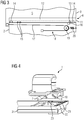
- Fig. 3 shows an exemplary embodiment of the displacement device 6 used in the first embodiment of the knee coil 1.
- the coil unit 3 and the connecting device 2 are schematically shown.
- the connecting device 2 comprises a guide rail 11 as a guide element of the displacement device 6.
- the guide element 12 of the frame 5 runs in the guide rail 11 and may, for example, comprise a protrusion and/or even one or more wheels 13 running in the guide rail 11.
- the guide rail 11 comprises two end stoppers 14 defining respective end positions of the coil unit 3, in particular the base position atop the connecting device 2 and the maximally displaced end position.
- a latching and/or snapping means can be provided to secure the coil unit 3 to the connecting device 2 when the coil unit 3 is in a corresponding end position.
- a latching and/or snapping means is not shown in fig. 3 , yet provided at least for the base position to facilitate transportation.
- Manual operating elements may be provided to unlock the latch- or snap fit.
- the displacement device 6 may also comprise braking and/or locking means to lock the coil unit 3 in an intermediate position.
- the guide rail 11 comprises an intermediate mechanical resistance element 15 which is provided at a distance of 3 cm away from the end stopper 14 of the maximally displaced position of the coil unit 3 relative to the connecting device 2. In this manner, haptic feedback is provided regarding this intermediate position.
- the displacement of the coil unit 3 can be stopped at the intermediate position defined by the resistance elements 15 and the knee of the patient can be positioned in the centre of the coil unit 3 while the patient is sitting. If the patient lies down to a horizontal position from the sitting position after the knee has been positioned with respect to the coil elements of the coil unit 3, the knee will be further displaced in the direction of the head of the patient, pulling the coil unit 3 over the correspondingly designed resistance element 15 closer to the end stopper 14 such that the relative position of the knee in the coil unit 3 does not change and the movement of the knee is compensated.
- the local knee coil may further comprise a way sensor 16, also shown in fig. 3 , which measures the displacement of the coil unit 3 relative to the connecting device 2, which is in a defined position once slidingly fitted into the direct connect socket of the patient table.
- the data of the way sensor 16 is communicated to a control device of the magnetic resonance imaging device to enable functions like, for example, auto-positioning.
- Fig. 3 further shows a possible embodiment of an electrical connection across the displacement device 6.
- corresponding connection wires 17 are guided using a dragchain device 18 having a pulley 19 supported against the restoring force of a spring 20.
- a sliding contact at least along a length proximal to the end stopper 14 of the maximally displaced end position may be used.
- FIG. 4 illustrates usage of the local knee coil 1 in a first step.
- a patient table 21 of a magnetic resonance imaging device comprises a direct connect socket 22 at a position such that a direct connect local head coil can be connected electrically and mechanically in one action.
- the socket 22 comprises guiding elements 23 corresponding to the guiding elements 9 of the connecting device 2.
- the connecting device 2 is slidingly fit into the direct connect socket 22, thereby also connecting the interface unit 10 to a corresponding interface unit of the direct connect socket 22.
- Fig. 5 shows the local knee coil 1 installed on the patient table 21, wherein the coil unit 3 is still in its base position.
- the coil unit 3 can be slidingly displaced from the connecting device 2 which remains fixed, i.e. positively connected, in the direct connect socket 22.
- Fig. 6 shows the coil unit 3 in its maximally displaced position, i.e. the knee position, on the patient table 21.
- the top 24 of the connecting device 2 is now exposed, in this embodiment forming a flat feet support element for the feet of the patient.
- the top 24 of the connecting device 2 may also comprise a recess for a feet support element 25 and/or a comfort element as feet support element 25, in particular a cushion.
- anatomy recess elements shaped for receiving a part of the anatomy of the patient for example the feet or lower legs, as feet support element 25, which may be provided as part of the top 24 or placed in corresponding recesses atop the connecting device 2.
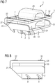
- FIGS 7 to 11 show a second embodiment of a local knee coil 1' according to the invention.
- corresponding components are marked with the same reference numerals.
- the second embodiment differs from the first embodiment mainly in the design of the displacement device 6, which in this case comprises two lateral hinges 27 so that a hinging frame 28 of the coil unit 3 may be swung out from a position atop the connecting device 2 to the knee position on the patient table 21.
- the hinging frame 28, in this case, comprises two lateral handles 7.
- the coil unit 3 is split into an upper coil unit part 29 and a lower coil unit part 30, such that the upper coil unit part 29 can also be attached to the lower coil unit part 30 when the latter is in a hinged position by corresponding attachment means, in particular hook means, not shown in fig. 1 to fig. 11 .
- connection means to connect the upper coil unit part 29 to the lower coil unit part 30 when the lower coil unit part 30 is swung out into the knee position (cf. fig. 11 ) .
- the top 24 of the connecting device 2 is formed into a recess 31 enclosing the lower coil unit part 30 largely when in the hinged position, i.e. the folded-up position. Electrical connections from the coil elements (again not shown) to the corresponding connectors of the interface unit 10 are, in this case, provided through the hinges 27.
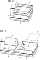
- the upper coil unit part 29 is first removed and, as shown in fig. 7 , the connecting device 2 is fittingly slid into the direct connect socket 22 of the patient table 21, so that the situation shown in fig. 10 results.
- the lower coil unit part 30 is then swung into the knee position on the patient table 21 by virtue of the hinges 27 as shown in fig. 11 . Thereafter, the upper coil unit part 29 is set on top of the lower coil unit part 30, which may happen after positioning of a knee of a patient inside the lower coil unit part 30.
- the recess 21 remains empty as soon as the lower coil unit part 30 is swung out, such that it can now be used to place a feet support element 25, in particular a cushion, inside this recess to bed the feet and lower legs of the patient comfortably.
- the top 24 of the connecting device 2 can also already comprise a cushion or anatomy recess elements shaped for receiving a part of the anatomy of the patient.
- FIGS 7 to 11 also show guide protrusions 32 along the hinging frame 28 which fit into guide recesses (not shown) in the patient table 21 to further stabilise the coil unit 3 in the knee position.
- guide protrusions can also be provided for the first embodiment.
- fig. 12 shows a less preferred embodiment of a local knee coil 1" according to the invention.
- the connecting device 2 still fitting inside the direct connect socket 22 of the patient table 21, is connected to the coil unit 3 using a short cable 33 which is guided laterally away from the space occupied by the patient.
- the feet support element 25 is attached on top of the connecting device 2.
- Fig. 13 shows a principle drawing of a magnetic resonance imaging device 34 according to the invention.
- the magnetic resonance imaging device 34 comprises a main magnet unit 35 defining a bore 36 into which the patient table 21, comprising the direct connect socket 22, can be transported.
- the magnetic resonance imaging device 34 also comprises at least one local knee coil 1, 1', 1" according to the invention.
Landscapes
- Health & Medical Sciences (AREA)
- Life Sciences & Earth Sciences (AREA)
- Physics & Mathematics (AREA)
- Medical Informatics (AREA)
- Surgery (AREA)
- Biophysics (AREA)
- Pathology (AREA)
- Engineering & Computer Science (AREA)
- Biomedical Technology (AREA)
- Heart & Thoracic Surgery (AREA)
- Veterinary Medicine (AREA)
- Molecular Biology (AREA)
- Public Health (AREA)
- Animal Behavior & Ethology (AREA)
- General Health & Medical Sciences (AREA)
- Nuclear Medicine, Radiotherapy & Molecular Imaging (AREA)
- General Physics & Mathematics (AREA)
- Condensed Matter Physics & Semiconductors (AREA)
- High Energy & Nuclear Physics (AREA)
- Radiology & Medical Imaging (AREA)
- Physical Education & Sports Medicine (AREA)
- Magnetic Resonance Imaging Apparatus (AREA)
Abstract
- a connecting device (2) for connecting to a socket (22) in the patient table (21), the connecting device (2) comprising at least one interface unit (10) for multiple channels corresponding to coil elements of the local knee coil (1, 1', 1") and connecting to a corresponding interface unit of the socket (22), and
- a coil unit (3) comprising the coil elements for sending excitation signals and/or receiving magnetic resonance signals,
wherein the connecting device (2) comprises at least one guiding element (9) to slidingly fit the connecting device (2) into the socket (22) which is displaced from the knee position on the patient table (21) and functions as a receptable for the connecting device (2), to form a positive connection and interconnect the interface units (10) during the slide-fit, and in that the local knee coil (1, 1', 1") further comprises a feet support element (25) for the feet of a patient whose knee extends through the coil unit (3) in the knee position, which is positioned or positionable on the top (24) of the connecting device (2).
Description
- The invention concerns a local knee coil for a patient table of a magnetic resonance imaging device, comprising
- a connecting device for connecting to a socket in the patient table, the connecting device comprising at least one interface unit for multiple channels corresponding to coil elements of the local knee coil and connecting to a corresponding interface unit of the socket, and
- a coil unit comprising the coil elements for sending excitation signals and/or receiving magnetic resonance signals. The invention further concerns a magnetic resonance imaging device.
- Magnetic resonance imaging is an established technique in medical areas, in particular diagnosis. Images with a high signal to noise ratio (SNR) can be acquired using so-called local coils. Local coils are antenna systems placed in close proximity to the patient, for example on the patient (anterior placement) or under the patient (posterior placement). Local coils usually comprise a plurality of coil elements, i.e. single antennas. During a magnetic resonance measurement, the excited nuclei induce voltages into the coil elements, which, as magnetic resonance signals, can, for example, be amplified using a low noise amplifier (LNA preamp) and can be transported via a cable to a receiving system of the magnetic resonance imaging device.
- The SNR can be further improved using high field systems, for example having a basic magnetic field strength of 1.5 T to 12 T and more.
- Each receiving coil element can be understood as defining a receiving channel. Usually, the number of coil elements used in a magnetic resonance imaging device is larger than the number of channels of a receiving system, so that a switch matrix may be used to route the currently active receiving channels (positioned in the field of view/homogeneity volume of the magnetic resonance imaging device) to the existing receivers. Thus, more coil elements than receivers can be used, since when the whole body of the patient is covered by coil elements, only the coil elements inside the field of view or inside the homogeneity volume, respectively, have to be read out.
- A local coil is an antenna system having one or more coil elements and may also be called coil array. The single coil elements can be provided as loop antennas, butterfly coils and/or saddle coils. In addition to the coil elements, a local coil may comprise a pre-amplifier (LNA), further electronic components, for example baluns, cables, a housing, and a connection assembly comprising a plug and cable to connect the local coil to the magnetic resonance imaging system, in particular using corresponding sockets of a patient table. The receivers of the receiving system of the magnetic resonance imaging device may filter and digitize a magnetic resonance signal received by the coil elements of the local coil and transfer the data to a digital signal processing system, so that an image and/or a spectrum can be derived from the magnetic resonance data. Images and spectra can be displayed to a user for diagnosis.
- Dedicated local coils have been proposed for imaging the lower extremities of a patient, for example the knees and the feet of the patient. To fulfil certain requirements of orthopaedic imaging, the local coils can be designed as transmitting as well as receiving coils. That is, not or not only the body coil enclosing the whole body is used to excite the atomic nuclei, but also or only the local coil, which only covers parts of the body. The same local coil is then also used to receive magnetic resonance signals. Two different concepts have been proposed. In a first concept, a transmitting coil element is also the receiving coil element, in a second concept, the transmitting coil elements and the receiving coil elements are electrically isolated and separated from each other, but mechanically provided in the same housing. This second concept allows receiving multiple channels simultaneously, accelerating the imaging process by using parallel imaging techniques and obtaining higher signal to noise ratio (SNR).
- The antennas of the second concept have the disadvantage that the mechanical design of the coil has to be chosen such that as many patients as possible fit into the local coil while having the local coil as proximate as possible to the patient. Usually, the local coils are designed to accommodate 80 to 98 % of the patients. However, for patients having larger extremities or patients wearing a bandage and/or having ankylosis, the narrow dimensioning of the housing of the local coil may not allow any movement or even placing the corresponding extremity inside the local coil. For many orthopaedic questions, however, imaging in different positions and/or real time imaging at, for example, 0.25 to 30 frames per second are of high significance. It is, for example, known to image a knee of a patient in different angular positions and/or image foot joints twisted and/or under load. This so-called functional imaging is very important in orthopaedic diagnosis. The electric and mechanical design of known local coils, however, hinders or even prevents these applications.
- Additionally, the contacting of the local coil has potential for improvement. In this field, so-called direct connect coils have been proposed as local head coils and/or local spine coils. Direct connect coils comprise a base comprising at least one guiding element to slidingly fit the base and thus the whole local head or spine coil into a corresponding direct connect circuit, such that the electrical connections to and from the coil elements are established. In this manner, no cables are required, since these local head or spine coils are immediately positioned in a suitable place on the patient table. Such a direct connect local head coil is, for example, known from
DE 10 2011 079 565 A1 , whileUS 9,250,302 B2 - However, direct connect sockets are only provided in the head area of a patient table, such that all remaining known local coils require cables, which, according to the type of local coil, can have different thicknesses, for example of 20 mm for pure receiving local coils, or 12 mm for receiving and transmitting local coils. The presence of the cable is disadvantageous when positioning patients on the patient table, since the cables can be damaged or get jammed. Also, safety issues ensue, since, for example, baluns inside the cables may malfunction, possibly leading to burns of the patient.
- Another problem specific for knee coils is that the patient's knee is positioned while the patient is sitting. As soon as the patient lies down to a horizontal position, the knee joint is displaced in the direction of the head of the patient. This displacement effect has to be taken into account.
- To solve these problems, it has been proposed to keep the cable as short as possible, in particular to reduce the danger of jamming, but also to increase the convenience of the patient. If the cable from the local coil to the next socket is as short as possible, the risk of an uncomfortable position of the patient on the cable, jamming of the cable and burns due to malfunctioning electronic components is reduced. It has also been proposed to use cushions having defined recesses to guide the cable and allow the patient to comfortably lie on the cushion. Furthermore, tube holders using guide rails or guide grooves of the patient table have been proposed. Local coils can be provided with exchangeable cables, which can be chosen in a length as short as possible and as required.
- In Chinese utility model application
201720201724.1 - Regarding the displacement effect when the patient moves from a sitting position to a lying position, it has been proposed to position the knee off-centre, displaced by an estimated movement distance. This estimation, however, performed by medical personal, is error-prone and may result in reduced quality of the magnetic resonance data.
- It is an object of the present invention to provide a local knee coil providing increased comfort for the patient and reducing the risk of damage and/or burns to the patient.
- This object is achieved by providing a local knee coil according to
claim 1 and a magnetic resonance imaging device according toclaim 14. Advantageous embodiments are described in the dependent claims. - A local knee coil for a patient table of a magnetic resonance imaging device according to the invention comprises
- a connecting device for connecting to a socket in the patient table, the connecting device comprising at least one interface unit for multiple channels corresponding to coil elements of the local knee coil and connecting to a corresponding interface unit of the socket, and
- a coil unit comprising the coil elements for sending excitation signals and/or receiving magnetic resonance signals, wherein the connecting device comprises at least one guiding element to slidingly fit the connecting device into the socket which is displaced from the knee position on the patient table and functions as a receptable for the connecting device, to form a positive connection and interconnect the interface units during the slide-fit, and wherein the local knee coil further comprises a feet support element for the feet of a patient whose knee extends through the coil unit in the knee position, wherein the feet support element is positioned or positionable on the top of the connecting element.
- Thus, the socket used is a direct connect socket, in particular a direct connect socket for a local head coil. The current invention proposes to use an extended plug, namely the connecting device, which fits into a direct connect socket of the patient table, i.e. uses guiding elements corresponding with guiding elements of the direct connect socket to slidingly fit the connecting device into the socket and at the same time establishing the electrical connections via the interface units. Additionally, the connecting device serves as a feet support element itself or provides a space for a feed support element. In particular, the feet support element may comprise a top portion of the connecting device, for example by providing the top of the connecting device with a cushion gutting out over the surface of the patient table.
- It is thus proposed to electrically connect the local knee coil using the direct connect socket of the patient table usually used for direct connect head coils. This allows minimal use of cables or even a construction in which no cables are needed, as discussed below. If the local knee coil comprises ab cable, the cable can be guided along lateral areas, in this manner preventing discomfort for the patient. The installation of the coil on the patient table is also facilitated since a direct connect socket is used, providing mechanical fit and electrical connection in one single action.
- The connecting device itself poses no obstacle in positioning the patient like known plugs do, since it is at least largely received in the direct connect socket and additionally provides the feed support unit even assisting in a comfortable positioning of a patient.
- In a less preferred embodiment, it may be provided that the connecting device and the coil unit are connected by a cable, so that the coil unit can be freely positioned, in particular at the knee position, while the cable is placed in lateral areas without contact to the legs or feet of the patient. In such an embodiment, the local knee coil has no plug, but is connected using the direct connect socket in the patient table by means of the connecting device. Cables are still present, but neither the cables nor the plug interfere with the positioning of the feet and lower legs of the patient. The connecting device may comprise recesses or the like for the feet/legs and/or at least parts of the feet supporting element, for example a cushion.
- However, in a preferred embodiment, the local knee coil is a modified direct connect coil without any cable visible or present on the outside of the local knee coil.
- Preferably, the local knee coil comprises an displacement device for displacing at least a part of the coil unit to the knee position on the patient table when the connecting device is connected in the socket. The displacement device may thus mechanically couple the coil unit and the connecting device to each other so that the coil unit can be displaced manually from the position of the direct connect socket to the corresponding knee position on the patient table, in particular using degrees of freedom provided by the displacement device. In this manner, the local knee coil construction is compact and provides easy handling by medical staff.
- In a first concrete embodiment, the displacement device comprises at least one guide element engaging a guide element of the coil unit to slidably move the coil unit into the knee position. In particular, the sliding movement of the coil unit follows a longitudinal direction of the patient table when installed. In other words, the displacement device comprises guide means, in particular at least on guide rail. In use, the connecting element is slid into the direct connect socket such that mechanical and electrical connection is provided. The coil unit, appropriately guided, can then be displaced/pulled out, in particular in the longitudinal direction of the patient table, to the knee position. In this manner, an area on top of the connecting device is exposed, which can be used for supporting the feet of the patient, in particular using cushions and/or recesses according to the anatomy. No cables and no plugs interfere with the positioning of the patient.
- Preferably, the coil unit may be provided comprising an assembly comprising the coil elements and a guide frame supporting the assembly, wherein in particular the guide frame comprises at least one handle for manually sliding the coil unit. Such a handle can also be used for transporting the local knee coil, comparable to a suitcase, when the coil unit is in its base position on top of the connecting device.
- To establish electrical contact between the coil elements and the interface unit of the connecting device, in a first option, the guide elements may comprise a sliding contact for electrically connecting the coil elements to the interface unit of the connecting device. In particular, the sliding contact does not have to span the whole length of possible displacement, since the presence of an electrical connection suffices in displacement positions in which the coil unit is to be used to acquire magnetic resonance signals.
- In a second option, providing permanent electrical connection, the local knee coil may comprise a cable guiding device, in particular a dragchain device, for internally guiding a cable (or wires, respectively) connecting the coil elements to the interface unit of the connecting device. Such a cable guiding device may comprise one or more guide pulleys for the cable. For example, a guide pulley may be fixed against a restoring force of a spring element in the coil unit or the connecting device, such that the cable is taut in each position of the coil unit relative to the connecting device.
- The guide elements of the displacement device may comprise a guide rail and corresponding protrusions engaging the guide rail, for example sword-shaped and/or U-shaped protrusions.
- The local knee coil of this first embodiment may further comprise a latching and/or snapping means to secure the coil unit to the connecting device when the coil unit is in its end position atop the connecting device (base position). It can also be provided that the guide elements of the displacement device comprise an end stopper defining an end position in which the coil unit is maximally displaced from the connecting device.
- In use, the coil unit may not be fully displaced into the end position, but at a distance of, for example, 2 - 5 cm from the end position. In this manner, when the patient, after placement of the knee inside the coil unit, lies down from a sitting position, the coil unit follows the ensuing movement of the knee in the direction of the head of the patient, maintaining the relative position of the coil elements and the knee. Using an displacement device with guide elements allowing sliding displacement of the coil unit of the local knee coil to the knee position on the patient table, the retraction effect when the patient lies down may be compensated, so that off-centre positioning of the knee in an estimated position can be omitted.
- In an especially preferred embodiment, the guide elements of the displacement device comprise at least one intermediate stopper displaced from an end stopper defining a maximum displacement of the coil unit and/or an intermediate mechanical resistance element displaced from the end stopper defining a maximum displacement of the coil unit. Preferably, the displacement of the intermediate stopper/resistance element from the end stopper of maximum displacement from the connecting device is chosen to be between 2 and 5 cm, in particular 3 cm. In this manner, ideal intermediate displacements of the coil unit for positioning the knee while the patient is still sitting are communicated to the medical staff and sufficient compensating length to compensate a movement of the knee when the patient lies down is retained. If the knee moves while the patient is lying down, the coil unit, guided by the displacement device, moves accordingly such that a centre position of the knee in the coil unit is maintained.
- The local knee coil of this embodiment may further comprise a way sensor for measuring displacement of the coil unit relative to the connecting device, in particular when the patient is lying down from a sitting position after the knee was positioned inside the coil unit. The displacement data may be communicated to a control device of the magnetic resonance imaging device, in particular using a connector of the interface units, and can, for example, be used for auto-positioning functions and the like. The position of the centre of the coil unit and/or the coil elements is thus always known to the control device.
- In a second, alternative concrete embodiment of the local knee coil according to the invention, the displacement device comprises a hinge connecting at least part of the coil unit to the connecting device, wherein the at least part of the coil can be swung out from atop the connecting device to the knee position. The local knee coil is therefore hinged or foldable. The connecting element, again functioning as a base, slides into the direct connect socket of the patient table, providing mechanical and electrical connection in one action. The coil unit or at least part of the coil unit, which may, again, comprise a hinging frame in addition to an assembly comprising the coil elements, may be swung into the knee position, whereafter, if applicable, additional coil unit parts may be added. The hinging frame, in particular also connecting hinges on both lateral sides of the local knee coil, can, again, comprise at least one handle facilitating the swinging of the coil into the knee position and the transportation of the local knee coil when folded up.
- Preferably, the coil unit is split into an upper coil unit part and a lower coil unit part, the hinge connecting the lower coil unit part and the connecting device such that the lower coil unit part can be swung out from atop the connecting device to the knee position, wherein the upper coil unit part can be set atop the lower coil unit part using connection means when the lower coil unit part is swung out. In use, the connecting device is first fittingly slid into a direct connect socket on the patient table, whereafter the lower coil unit part is swung out to the knee position and the upper coil unit part is added, for example by locking it in place by a snap-in locking device as connection means.
- In such a configuration, the connecting device preferably comprises a recess for the lower coil unit part, wherein the feet support element is positionable in the recess when the lower coil unit part is swung out. The lower coil unit part is preferably at least almost completely accommodated in the recess when swung in. Folded up, the lower coil unit part at least partly "vanishes" inside the recess of the connecting device. If the lower coil unit part is swung out of the recess, the recess is used as a support for the feet support element, for example a cushion.
- Preferably, attachment means, in particular hook means, are provided to attach the upper coil unit part to the lower coil unit part and/or the connecting device when the lower coil unit part and the connecting device are in hinged position (folded up). As explained above, it is preferred that the lower coil unit part is retracted into the recess in this hinged position. The upper coil unit part can be attached to the assembly of the connecting device and the lower coil unit part for transportation. If the local knee coil is to be used for a magnetic resonance measurement, the upper coil unit part is removed from this assembly, the connecting device is slid into the direct connect socket and the lower coil unit part is swung out. The patient can be positioned and the coil unit can be closed by adding the upper coil unit part. After this, the imaging can commence.
- It is noted that, in this second concrete embodiment, the electrical connection between the coil elements and the interface unit can be guided through the at least one hinge, as in principle known.
- As already explained, it is preferred that an assembly comprising the coil elements is supported by a frame, in particular a guide frame or a hinging frame, which in particular comprises at least one handle for manually displacing the coil unit and/or transporting the local knee coil. Using the handle, the local knee coil can be easily transported with one hand. With the coil unit in its base position and, if applicable, the upper coil unit part attached, the local knee coil is compact and easy to carry using the handle. Due to the compact design of the local knee coil, it is also easily stowed away.
- The provision of a frame also advantageously allows the realisation of an adjustment device for fine-adjusting the assembly including the coil elements carried by the frame. For example, such an adjustment device may allow lateral movement of the assembly relative to the guide frame for fine-positioning of the assembly and thus the coil elements to accommodate the patient as comfortable as possible.
- In an advantageous, general, further embodiment of the invention, the local coil unit has at least one guiding protrusion and/or guiding recess interoperable with a corresponding guiding recess and/or guiding protrusion of the patient table. Often, patient tables of magnetic resonance imaging devices include guiding recesses, which can also be used by the coil unit to aid in positioning the coil unit at the knee position, in particular when the displacement device provides a certain clearance and/or backlash.
- Preferably, the feet support element comprises at least one cushion and/or at least one anatomy recess element shaped for receiving a part of the anatomy of the patient. In this manner, a comfortable positioning of the patient is achieved.
- The invention further concerns a magnetic resonance imaging device, comprising a patient table with a direct connect socket, in particular for a head coil, and a local knee coil according to the invention for connecting to the direct connect socket. All remarks regarding the local knee coil according to the invention also apply to the magnetic resonance imaging device, thus yielding the same advantages.
- In particular, the interface unit of the direct connect socket comprises connectors for sending excitation signals and receiving magnetic resonance signals. In this manner, the local knee coil and its coil elements can be used for transmitting as well for receiving (TX and RX). In an alternative embodiment, if the interface unit of the direct connect socket only comprises connectors for receiving magnetic resonance signals, the magnetic resonance imaging device may comprise an inductive coupling device for communicating excitation signals to the local knee coil, as known in the state of the art.
- Further details and advantages of the present invention can be taken from the following description of exemplary embodiments in conjunction with the drawings, in which
- Fig. 1
- shows a perspective view of a first embodiment of a local knee coil according to the invention,
- Fig. 2
- shows a side view of the local knee coil of
fig. 1 , - Fig. 3
- shows a detail of the displacement device and electrical connections in the first embodiment,
- Fig. 4
- illustrates a first step in using the local knee coil according to the first embodiment,
- Fig. 5
- shows the local knee coil according to the first embodiment installed on a patient table,
- Fig. 6
- illustrates a further step when using a local knee coil according to the first embodiment,
- Fig. 7
- shows a perspective view of a local knee coil according to a second embodiment of the invention,
- Fig. 8
- shows a side view of the local knee coil of
fig. 7 , - Fig. 9
- illustrates a first step of installing the local knee coil according to the second embodiment on a patient table,
- Fig. 10
- shows a perspective view of a local knee coil according to a second embodiment installed on a patient table,
- Fig. 11
- shows the local knee coil of the second embodiment in a measurement position,
- Fig. 12
- is a principle drawing of a third embodiment of a local knee coil according to the invention, and
- Fig. 13
- shows a magnetic resonance imaging device according to the invention.
-
Fig. 1 shows a first embodiment of alocal knee coil 1 according to the invention in a perspective view.Fig. 2 shows a side view. - As can be seen, the
local knee coil 1 comprises a connectingdevice 2 and acoil unit 3, thecoil unit 3 comprising anassembly 4 for the coil elements (not shown) of thelocal knee coil 1 and aguide frame 5 carrying theassembly 4. Thecoil unit 3 is connected to the connectingdevice 2 by adisplacement device 6 only indicated infig. 2 . Thedisplacement device 6 comprises guide means, in particular guide elements, to allow a sliding displacement of thecoil unit 3 relative to the connectingdevice 2 along the longitudinal direction of a patient table, which is the left-right-direction offig. 2 . Thedisplacement device 6 will be further described below with respect tofig. 3 . - The
guide frame 5, on the one hand, comprises at least onehandle 7 which facilitates transportation of thelocal knee coil 1 when thecoil unit 3 is in its base position (the end position atop the connecting device 2) as well as the displacement of thecoil 3 relative to the connectingdevice 2. Additionally, an adjustment device allowing lateral movement of theassembly 4 may be provided, as indicated by thelateral clearances 8 visible infig. 1 .Handles 7 may be provided on both longitudinal sides of theframe 5. - The connecting
device 2 is adapted to slide-fit into a direct connect socket of a patient table, as will be described further below. To facilitate this sliding-fit into a positive mechanical connection and electrical connection of interface units in one action, guidingelements 9, in this case sword-shaped, are provided at the sides of the connectingdevice 2. Theinterface unit 10 is only indicated in the figures and comprises connectors at least for each of the coil elements, wherein in this case the corresponding direct connect socket also supplies data for transmitting excitation signals by the coil elements. In such a case, the connectingdevice 2, which can also be termed a base of thelocal knee coil 1, may also house electronic/electrical components related to the transmitting functionality (TX) of thelocal knee coil 1. - It is noted that, alternatively, TX data may also be communicated by induction, so that the local knee coil 1 (as well as the further embodiments) may also comprise an inductive coupling device for TX.
-
Fig. 3 shows an exemplary embodiment of thedisplacement device 6 used in the first embodiment of theknee coil 1. Thecoil unit 3 and the connectingdevice 2 are schematically shown. In this embodiment, the connectingdevice 2 comprises aguide rail 11 as a guide element of thedisplacement device 6. Theguide element 12 of theframe 5 runs in theguide rail 11 and may, for example, comprise a protrusion and/or even one ormore wheels 13 running in theguide rail 11. Theguide rail 11 comprises twoend stoppers 14 defining respective end positions of thecoil unit 3, in particular the base position atop the connectingdevice 2 and the maximally displaced end position. Associated with at least one of theend stoppers 14 or as part of the respective end stoppers 14 a latching and/or snapping means can be provided to secure thecoil unit 3 to the connectingdevice 2 when thecoil unit 3 is in a corresponding end position. Such a latching and/or snapping means is not shown infig. 3 , yet provided at least for the base position to facilitate transportation. Manual operating elements may be provided to unlock the latch- or snap fit. In other embodiments, thedisplacement device 6 may also comprise braking and/or locking means to lock thecoil unit 3 in an intermediate position. - In this preferred embodiment, however, the
guide rail 11 comprises an intermediatemechanical resistance element 15 which is provided at a distance of 3 cm away from theend stopper 14 of the maximally displaced position of thecoil unit 3 relative to the connectingdevice 2. In this manner, haptic feedback is provided regarding this intermediate position. - The displacement of the
coil unit 3 can be stopped at the intermediate position defined by theresistance elements 15 and the knee of the patient can be positioned in the centre of thecoil unit 3 while the patient is sitting. If the patient lies down to a horizontal position from the sitting position after the knee has been positioned with respect to the coil elements of thecoil unit 3, the knee will be further displaced in the direction of the head of the patient, pulling thecoil unit 3 over the correspondingly designedresistance element 15 closer to theend stopper 14 such that the relative position of the knee in thecoil unit 3 does not change and the movement of the knee is compensated. - The local knee coil may further comprise a
way sensor 16, also shown infig. 3 , which measures the displacement of thecoil unit 3 relative to the connectingdevice 2, which is in a defined position once slidingly fitted into the direct connect socket of the patient table. The data of theway sensor 16 is communicated to a control device of the magnetic resonance imaging device to enable functions like, for example, auto-positioning. -
Fig. 3 further shows a possible embodiment of an electrical connection across thedisplacement device 6. In this case, correspondingconnection wires 17 are guided using adragchain device 18 having apulley 19 supported against the restoring force of aspring 20. Alternatively, a sliding contact at least along a length proximal to theend stopper 14 of the maximally displaced end position may be used. -
Fig. 4 illustrates usage of thelocal knee coil 1 in a first step. A patient table 21 of a magnetic resonance imaging device comprises adirect connect socket 22 at a position such that a direct connect local head coil can be connected electrically and mechanically in one action. As can be seen, thesocket 22 comprises guidingelements 23 corresponding to the guidingelements 9 of the connectingdevice 2. By cooperation of theguide elements device 2 is slidingly fit into thedirect connect socket 22, thereby also connecting theinterface unit 10 to a corresponding interface unit of thedirect connect socket 22. -
Fig. 5 shows thelocal knee coil 1 installed on the patient table 21, wherein thecoil unit 3 is still in its base position. Using, for example, one of thehandles 7, thecoil unit 3 can be slidingly displaced from the connectingdevice 2 which remains fixed, i.e. positively connected, in thedirect connect socket 22. -
Fig. 6 shows thecoil unit 3 in its maximally displaced position, i.e. the knee position, on the patient table 21. As can be seen, the top 24 of the connectingdevice 2 is now exposed, in this embodiment forming a flat feet support element for the feet of the patient. However, the top 24 of the connectingdevice 2 may also comprise a recess for afeet support element 25 and/or a comfort element as feet supportelement 25, in particular a cushion. Finally, it is also possible to use anatomy recess elements shaped for receiving a part of the anatomy of the patient, for example the feet or lower legs, as feet supportelement 25, which may be provided as part of the top 24 or placed in corresponding recesses atop the connectingdevice 2. - It is noted that the
further sockets 26 of the patient table 21 do not have to be used, such that no plugs and/or cables hinder positioning of the patient. -
Figures 7 to 11 show a second embodiment of a local knee coil 1' according to the invention. For the sake of simplicity, corresponding components are marked with the same reference numerals. - The second embodiment differs from the first embodiment mainly in the design of the
displacement device 6, which in this case comprises two lateral hinges 27 so that ahinging frame 28 of thecoil unit 3 may be swung out from a position atop the connectingdevice 2 to the knee position on the patient table 21. Thehinging frame 28, in this case, comprises two lateral handles 7. - As can also be seen from
fig. 7 to fig. 11 , thecoil unit 3 is split into an uppercoil unit part 29 and a lowercoil unit part 30, such that the uppercoil unit part 29 can also be attached to the lowercoil unit part 30 when the latter is in a hinged position by corresponding attachment means, in particular hook means, not shown infig. 1 to fig. 11 . Also not shown are connection means to connect the uppercoil unit part 29 to the lowercoil unit part 30 when the lowercoil unit part 30 is swung out into the knee position (cf.fig. 11 ) . - As can also be seen from the figures, the top 24 of the connecting
device 2 is formed into arecess 31 enclosing the lowercoil unit part 30 largely when in the hinged position, i.e. the folded-up position. Electrical connections from the coil elements (again not shown) to the corresponding connectors of theinterface unit 10 are, in this case, provided through thehinges 27. - To use the local knee coil 1', the upper
coil unit part 29 is first removed and, as shown infig. 7 , the connectingdevice 2 is fittingly slid into thedirect connect socket 22 of the patient table 21, so that the situation shown infig. 10 results. - The lower
coil unit part 30 is then swung into the knee position on the patient table 21 by virtue of thehinges 27 as shown infig. 11 . Thereafter, the uppercoil unit part 29 is set on top of the lowercoil unit part 30, which may happen after positioning of a knee of a patient inside the lowercoil unit part 30. - As can also be seen from
fig. 11 , therecess 21 remains empty as soon as the lowercoil unit part 30 is swung out, such that it can now be used to place afeet support element 25, in particular a cushion, inside this recess to bed the feet and lower legs of the patient comfortably. In an alternative embodiment, the top 24 of the connectingdevice 2 can also already comprise a cushion or anatomy recess elements shaped for receiving a part of the anatomy of the patient. -
Figures 7 to 11 also show guide protrusions 32 along the hingingframe 28 which fit into guide recesses (not shown) in the patient table 21 to further stabilise thecoil unit 3 in the knee position. Such guide protrusions can also be provided for the first embodiment. - Finally,
fig. 12 shows a less preferred embodiment of alocal knee coil 1" according to the invention. In this case, the connectingdevice 2, still fitting inside thedirect connect socket 22 of the patient table 21, is connected to thecoil unit 3 using ashort cable 33 which is guided laterally away from the space occupied by the patient. The feet supportelement 25 is attached on top of the connectingdevice 2. -
Fig. 13 shows a principle drawing of a magneticresonance imaging device 34 according to the invention. The magneticresonance imaging device 34 comprises amain magnet unit 35 defining abore 36 into which the patient table 21, comprising thedirect connect socket 22, can be transported. The magneticresonance imaging device 34 also comprises at least onelocal knee coil - Although the present invention has been described in detail with reference to the preferred embodiment, the present invention is not limited by the disclosed examples from which the skilled person is able to derive other variations without departing from the scope of the invention.
Claims (15)
- Local knee coil (1, 1', 1'') for a patient table (21) (21) of a magnetic resonance imaging device (34), comprising- a connecting device (2) for connecting to a socket (22) in the patient table (21), the connecting device (2) comprising at least one interface unit (10) for multiple channels corresponding to coil elements of the local knee coil (1, 1', 1'') and connecting to a corresponding interface unit of the socket (22), and- a coil unit (3) comprising the coil elements for sending excitation signals and/or receiving magnetic resonance signals,characterized in that the connecting device (2) comprises at least one guiding element (9) to slidingly fit the connecting device (2) into the socket (22) which is displaced from the knee position on the patient table (21) and functions as a receptable for the connecting device (2), to form a positive connection and interconnect the interface units (10) during the slide-fit, and in that the local knee coil (1, 1', 1'') further comprises a feet support element (25) for the feet of a patient whose knee extends through the coil unit (3) in the knee position, which is positioned or positionable on the top (24) of the connecting device (2).
- Local knee coil according to claim 1, characterized in that it comprises an displacement device (6) for displacing at least a part of the coil unit (3) to the knee position on the patient table (21) when the connecting device (2) is connected in the socket (22).
- Local knee coil according to claim 2, characterized in that the displacement device (6) comprises at least on guide element (11) of the connecting device (2) engaging a guide element (12) of the coil unit (3) to slidably move the coil unit (3) into the knee position.
- Local knee coil according to claim 3, characterized in that the guide elements (11, 12) comprise a sliding contact for electrically connecting the coil elements to the interface unit (10) of the connecting device (2).
- Local knee coil according to claim 3, characterized in that it comprises a cable guiding device, in particular a dragchain device (18), for internally guiding a cable (17) connecting the coil elements to the interface unit (10) of the connecting device (2).
- Local knee coil according to any of the claims 3 to 5, characterized in that the guide elements (11, 12) comprise at least one intermediate stopper displaced from an end stopper (14) defining a maximum displacement of the coil unit (3) and/or an intermediate mechanical resistance element (15) displaced from the end stopper (14) defining a maximum displacement of the coil unit (3).
- Local knee coil according to claim 2, characterized in that the displacement device (6) comprises a hinge (27) connecting at least part of the coil unit (3) to the connecting device (2), wherein the at least part of the coil unit (3) can be swung out from atop the connecting device (2) to the knee position.
- Local knee coil according to claim 7, characterized in that the coil unit (3) is split into an upper coil unit part (29) and a lower coil unit part (30), the hinge (27) connecting the lower coil unit part (30) and the connecting device (2) such that the lower coil unit part (30) can be swung out from atop the connecting device (2) to the knee position, wherein the upper coil unit part (29) can be set atop the lower coil unit part (30) using connection means when the lower coil unit part (30) is swung out.
- Local knee coil according to claim 8, characterized in that the connecting device (2) comprises a recess (31) for the lower coil unit part (30), wherein the feet support element (25) is positionable in the recess (31) when the lower coil unit part (30) is swung out.
- Local knee coil according to claim 8 or 9, characterized in that attachment means, in particular hook means, are provided to attach the upper coil unit part (29) to the lower coil unit part (30) and/or the connecting device (2) when the lower coil unit part (30) and the connecting device (2) are in hinged position.
- Local knee coil according to any of the claims 2 to 10, characterized in that an assembly (4) comprising the coil elements is supported by a frame (5, 28).
- Local knee coil according to claim 11, characterized in that the frame comprises at least one handle (7) for manually displacing the coil unit (3) and/or transporting the local knee coil (1, 1', 1''), in particular when the coil unit (3) is in its base position and/or the upper coil unit part (29) is attached.
- Local knee coil according to one of the preceding claims, characterized in that at least the coil unit (3) has at least one guiding protrusion (32) and/or guiding recess interoperable with a corresponding guiding recess and/or guiding protrusion of the patient table (21).
- Local knee coil according to one of the preceding claims, characterized in that the feet support element (25) comprises at least one cushion and/or or least one anatomy recess element shaped for receiving a part of the anatomy of the patient.
- Magnetic resonance device imaging (34), comprising a patient table (21) with a direct connect socket (22), in particular for a head coil, and a local knee coil (1, 1', 1'') according to one of the preceding claims for connecting to the direct connect socket (22).
Priority Applications (3)
| Application Number | Priority Date | Filing Date | Title |
|---|---|---|---|
| EP17198790.2A EP3476289B1 (en) | 2017-10-27 | 2017-10-27 | Local knee coil for a magnetic resonance imaging device and magnetic resonance imaging device |
| CN201811253870.4A CN109725272B (en) | 2017-10-27 | 2018-10-25 | Local knee coil for magnetic resonance imaging device and magnetic resonance imaging device |
| US16/170,447 US11067651B2 (en) | 2017-10-27 | 2018-10-25 | Local knee coil for a magnetic resonance imaging device |
Applications Claiming Priority (1)
| Application Number | Priority Date | Filing Date | Title |
|---|---|---|---|
| EP17198790.2A EP3476289B1 (en) | 2017-10-27 | 2017-10-27 | Local knee coil for a magnetic resonance imaging device and magnetic resonance imaging device |
Publications (2)
| Publication Number | Publication Date |
|---|---|
| EP3476289A1 true EP3476289A1 (en) | 2019-05-01 |
| EP3476289B1 EP3476289B1 (en) | 2019-11-27 |
Family
ID=60191170
Family Applications (1)
| Application Number | Title | Priority Date | Filing Date |
|---|---|---|---|
| EP17198790.2A Active EP3476289B1 (en) | 2017-10-27 | 2017-10-27 | Local knee coil for a magnetic resonance imaging device and magnetic resonance imaging device |
Country Status (3)
| Country | Link |
|---|---|
| US (1) | US11067651B2 (en) |
| EP (1) | EP3476289B1 (en) |
| CN (1) | CN109725272B (en) |
Families Citing this family (5)
| Publication number | Priority date | Publication date | Assignee | Title |
|---|---|---|---|---|
| EP3808265B1 (en) * | 2019-10-16 | 2024-02-28 | Esaote S.p.A. | Patient support device, such as a patient bed, table or chair, for use with magnetic resonance imaging apparatuses |
| DE102019218285A1 (en) * | 2019-11-26 | 2021-05-27 | Siemens Healthcare Gmbh | Head coil arrangement with automatically positionable transmitter coil unit |
| CN117008026A (en) * | 2022-04-28 | 2023-11-07 | 西门子(深圳)磁共振有限公司 | Coil interface devices, coil devices and magnetic resonance imaging equipment |
| WO2024086658A1 (en) * | 2022-10-18 | 2024-04-25 | Medical Devices Corner Inc. | Platform for mounting devices inside scanner bores |
| CN118436334B (en) * | 2024-05-22 | 2024-10-01 | 中国人民解放军总医院第四医学中心 | Angle adjustment device for magnetic resonance examination of body parts |
Citations (5)
| Publication number | Priority date | Publication date | Assignee | Title |
|---|---|---|---|---|
| US5066915A (en) * | 1989-06-28 | 1991-11-19 | Siemens-Asahi Medical System, Ltd. | RF coil positioning device for MRI |
| US20100315085A1 (en) * | 2009-06-16 | 2010-12-16 | Brian Brown | Modular Apparatus for Magnetic Resonance Imaging |
| US20130023756A1 (en) * | 2011-07-21 | 2013-01-24 | Siemens Aktiengesellschaft | Adapter for a direct-connection head coil with adjustable tilt angle |
| DE102011079565A1 (en) | 2011-07-21 | 2013-01-24 | Siemens Ag | Head coil for magnetic resonance imaging apparatus, has lower part and upper part that is positioned over lower part, where lower part has lower part-base and lower part-head-bearing-part that is movable relative to lower part-base |
| US20130097780A1 (en) * | 2011-04-08 | 2013-04-25 | Stephan Biber | Imaging device for a joint of a human |
Family Cites Families (8)
| Publication number | Priority date | Publication date | Assignee | Title |
|---|---|---|---|---|
| US7970452B2 (en) * | 2003-09-30 | 2011-06-28 | Hologic, Inc. | Open architecture imaging apparatus and coil system for magnetic resonance imaging |
| US20110030698A1 (en) * | 2009-08-06 | 2011-02-10 | Kaufman Kenton R | Mri compatible knee positioning device |
| DE102010020153A1 (en) | 2010-05-11 | 2011-11-17 | Siemens Aktiengesellschaft | Combinable multi-part surface coil for magnetic resonance tomography |
| DE102012213594B4 (en) | 2012-08-01 | 2016-07-28 | Siemens Healthcare Gmbh | MR surface coil with integrated automatic patient fixation |
| DE102014210657A1 (en) * | 2014-06-04 | 2016-01-07 | Siemens Aktiengesellschaft | Axis-displaceable local coil |
| KR101774394B1 (en) * | 2015-12-11 | 2017-09-04 | 삼성전자주식회사 | Rf coil and magnetic resonance imaging device including the same |
| CN207837547U (en) | 2017-03-02 | 2018-09-11 | 西门子(深圳)磁共振有限公司 | A kind of coil device and pedestal |
| CN106872918B (en) | 2017-04-01 | 2024-05-24 | 北京大学第三医院(北京大学第三临床医学院) | MRI local coil base, local coil assembly and ankle coil assembly |
-
2017
- 2017-10-27 EP EP17198790.2A patent/EP3476289B1/en active Active
-
2018
- 2018-10-25 CN CN201811253870.4A patent/CN109725272B/en active Active
- 2018-10-25 US US16/170,447 patent/US11067651B2/en not_active Expired - Fee Related
Patent Citations (6)
| Publication number | Priority date | Publication date | Assignee | Title |
|---|---|---|---|---|
| US5066915A (en) * | 1989-06-28 | 1991-11-19 | Siemens-Asahi Medical System, Ltd. | RF coil positioning device for MRI |
| US20100315085A1 (en) * | 2009-06-16 | 2010-12-16 | Brian Brown | Modular Apparatus for Magnetic Resonance Imaging |
| US20130097780A1 (en) * | 2011-04-08 | 2013-04-25 | Stephan Biber | Imaging device for a joint of a human |
| US20130023756A1 (en) * | 2011-07-21 | 2013-01-24 | Siemens Aktiengesellschaft | Adapter for a direct-connection head coil with adjustable tilt angle |
| DE102011079565A1 (en) | 2011-07-21 | 2013-01-24 | Siemens Ag | Head coil for magnetic resonance imaging apparatus, has lower part and upper part that is positioned over lower part, where lower part has lower part-base and lower part-head-bearing-part that is movable relative to lower part-base |
| US9250302B2 (en) | 2011-07-21 | 2016-02-02 | Siemens Aktiengesellschaft | Adapter for a direct-connection head coil with adjustable tilt angle |
Also Published As
| Publication number | Publication date |
|---|---|
| US20190128978A1 (en) | 2019-05-02 |
| US11067651B2 (en) | 2021-07-20 |
| CN109725272B (en) | 2021-07-23 |
| EP3476289B1 (en) | 2019-11-27 |
| CN109725272A (en) | 2019-05-07 |
Similar Documents
| Publication | Publication Date | Title |
|---|---|---|
| US11067651B2 (en) | Local knee coil for a magnetic resonance imaging device | |
| EP1448095B1 (en) | Medical imaging system | |
| EP2699922B1 (en) | Mri involving a local rf coil being movable relative to a pediatric patient carrier | |
| FI86687B (en) | PATIENTBAEDD FOER MAGNETAVBILDNINGSANORDNING. | |
| EP3273924B1 (en) | Safe infant mr imaging system | |
| US8952694B2 (en) | Magnetic resonance coil device | |
| CN101385647B (en) | Patient support | |
| US10543141B2 (en) | Isolette environment controller and method | |
| US20150141802A1 (en) | Open architecture tabletop patient support and coil system | |
| US20040102690A1 (en) | Medical examination and /or treatment device with a transport carriage for a patient bed and transport carriage | |
| US20120256633A1 (en) | Receiving coil and local coil for magnetic resonance applications | |
| EP2096454A2 (en) | Open architecture imaging apparatus and coil system for magnetic resonance imaging | |
| US20140323851A1 (en) | Subject placement and head positioning device | |
| EP3033628B1 (en) | Rf transmission coil assembly for magnetic resonance imaging | |
| CN103293496A (en) | Shoulder local coil system for a magnetic resonance tomography system | |
| US9835699B2 (en) | Fail-safe and easy access lock for MRI receiver coil | |
| US20070287908A1 (en) | Medical Imaging System | |
| US10905330B2 (en) | Modular patient and antenna support structure for magnetic resonance imaging | |
| US9610050B2 (en) | Imaging device for a joint of a human | |
| CN215502990U (en) | Magnetic resonance system with a patient support | |
| CN211911610U (en) | Magnetic resonance apparatus with table cable unit | |
| EP2348991A2 (en) | Immobilization apparatus for medical imaging | |
| CN218956782U (en) | Carotid artery coil device, carotid artery coil assembly and head and neck coil assembly | |
| CA3212270A1 (en) | Head coil system and methods | |
| CN111904421A (en) | Magnetic resonance apparatus and coil structure thereof |
Legal Events
| Date | Code | Title | Description |
|---|---|---|---|
| PUAI | Public reference made under article 153(3) epc to a published international application that has entered the european phase |
Free format text: ORIGINAL CODE: 0009012 |
|
| STAA | Information on the status of an ep patent application or granted ep patent |
Free format text: STATUS: REQUEST FOR EXAMINATION WAS MADE |
|
| STAA | Information on the status of an ep patent application or granted ep patent |
Free format text: STATUS: EXAMINATION IS IN PROGRESS |
|
| 17P | Request for examination filed |
Effective date: 20180419 |
|
| AK | Designated contracting states |
Kind code of ref document: A1 Designated state(s): AL AT BE BG CH CY CZ DE DK EE ES FI FR GB GR HR HU IE IS IT LI LT LU LV MC MK MT NL NO PL PT RO RS SE SI SK SM TR |
|
| AX | Request for extension of the european patent |
Extension state: BA ME |
|
| 17Q | First examination report despatched |
Effective date: 20190418 |
|
| GRAP | Despatch of communication of intention to grant a patent |
Free format text: ORIGINAL CODE: EPIDOSNIGR1 |
|
| STAA | Information on the status of an ep patent application or granted ep patent |
Free format text: STATUS: GRANT OF PATENT IS INTENDED |
|
| INTG | Intention to grant announced |
Effective date: 20190703 |
|
| GRAS | Grant fee paid |
Free format text: ORIGINAL CODE: EPIDOSNIGR3 |
|
| GRAA | (expected) grant |
Free format text: ORIGINAL CODE: 0009210 |
|
| STAA | Information on the status of an ep patent application or granted ep patent |
Free format text: STATUS: THE PATENT HAS BEEN GRANTED |
|
| AK | Designated contracting states |
Kind code of ref document: B1 Designated state(s): AL AT BE BG CH CY CZ DE DK EE ES FI FR GB GR HR HU IE IS IT LI LT LU LV MC MK MT NL NO PL PT RO RS SE SI SK SM TR |
|
| REG | Reference to a national code |
Ref country code: GB Ref legal event code: FG4D |
|
| REG | Reference to a national code |
Ref country code: CH Ref legal event code: EP |
|
| REG | Reference to a national code |
Ref country code: AT Ref legal event code: REF Ref document number: 1205806 Country of ref document: AT Kind code of ref document: T Effective date: 20191215 |
|
| REG | Reference to a national code |
Ref country code: DE Ref legal event code: R096 Ref document number: 602017009087 Country of ref document: DE |
|
| REG | Reference to a national code |
Ref country code: IE Ref legal event code: FG4D |
|
| REG | Reference to a national code |
Ref country code: NL Ref legal event code: MP Effective date: 20191127 |
|
| REG | Reference to a national code |
Ref country code: LT Ref legal event code: MG4D |
|
| REG | Reference to a national code |
Ref country code: CH Ref legal event code: NV Representative=s name: SIEMENS SCHWEIZ AG, CH |
|
| PG25 | Lapsed in a contracting state [announced via postgrant information from national office to epo] |
Ref country code: LT Free format text: LAPSE BECAUSE OF FAILURE TO SUBMIT A TRANSLATION OF THE DESCRIPTION OR TO PAY THE FEE WITHIN THE PRESCRIBED TIME-LIMIT Effective date: 20191127 Ref country code: GR Free format text: LAPSE BECAUSE OF FAILURE TO SUBMIT A TRANSLATION OF THE DESCRIPTION OR TO PAY THE FEE WITHIN THE PRESCRIBED TIME-LIMIT Effective date: 20200228 Ref country code: NL Free format text: LAPSE BECAUSE OF FAILURE TO SUBMIT A TRANSLATION OF THE DESCRIPTION OR TO PAY THE FEE WITHIN THE PRESCRIBED TIME-LIMIT Effective date: 20191127 Ref country code: SE Free format text: LAPSE BECAUSE OF FAILURE TO SUBMIT A TRANSLATION OF THE DESCRIPTION OR TO PAY THE FEE WITHIN THE PRESCRIBED TIME-LIMIT Effective date: 20191127 Ref country code: NO Free format text: LAPSE BECAUSE OF FAILURE TO SUBMIT A TRANSLATION OF THE DESCRIPTION OR TO PAY THE FEE WITHIN THE PRESCRIBED TIME-LIMIT Effective date: 20200227 Ref country code: LV Free format text: LAPSE BECAUSE OF FAILURE TO SUBMIT A TRANSLATION OF THE DESCRIPTION OR TO PAY THE FEE WITHIN THE PRESCRIBED TIME-LIMIT Effective date: 20191127 Ref country code: FI Free format text: LAPSE BECAUSE OF FAILURE TO SUBMIT A TRANSLATION OF THE DESCRIPTION OR TO PAY THE FEE WITHIN THE PRESCRIBED TIME-LIMIT Effective date: 20191127 Ref country code: BG Free format text: LAPSE BECAUSE OF FAILURE TO SUBMIT A TRANSLATION OF THE DESCRIPTION OR TO PAY THE FEE WITHIN THE PRESCRIBED TIME-LIMIT Effective date: 20200227 |
|
| PG25 | Lapsed in a contracting state [announced via postgrant information from national office to epo] |
Ref country code: RS Free format text: LAPSE BECAUSE OF FAILURE TO SUBMIT A TRANSLATION OF THE DESCRIPTION OR TO PAY THE FEE WITHIN THE PRESCRIBED TIME-LIMIT Effective date: 20191127 Ref country code: IS Free format text: LAPSE BECAUSE OF FAILURE TO SUBMIT A TRANSLATION OF THE DESCRIPTION OR TO PAY THE FEE WITHIN THE PRESCRIBED TIME-LIMIT Effective date: 20200327 Ref country code: HR Free format text: LAPSE BECAUSE OF FAILURE TO SUBMIT A TRANSLATION OF THE DESCRIPTION OR TO PAY THE FEE WITHIN THE PRESCRIBED TIME-LIMIT Effective date: 20191127 |
|
| PG25 | Lapsed in a contracting state [announced via postgrant information from national office to epo] |
Ref country code: AL Free format text: LAPSE BECAUSE OF FAILURE TO SUBMIT A TRANSLATION OF THE DESCRIPTION OR TO PAY THE FEE WITHIN THE PRESCRIBED TIME-LIMIT Effective date: 20191127 |
|
| PG25 | Lapsed in a contracting state [announced via postgrant information from national office to epo] |
Ref country code: DK Free format text: LAPSE BECAUSE OF FAILURE TO SUBMIT A TRANSLATION OF THE DESCRIPTION OR TO PAY THE FEE WITHIN THE PRESCRIBED TIME-LIMIT Effective date: 20191127 Ref country code: PT Free format text: LAPSE BECAUSE OF FAILURE TO SUBMIT A TRANSLATION OF THE DESCRIPTION OR TO PAY THE FEE WITHIN THE PRESCRIBED TIME-LIMIT Effective date: 20200419 Ref country code: EE Free format text: LAPSE BECAUSE OF FAILURE TO SUBMIT A TRANSLATION OF THE DESCRIPTION OR TO PAY THE FEE WITHIN THE PRESCRIBED TIME-LIMIT Effective date: 20191127 Ref country code: RO Free format text: LAPSE BECAUSE OF FAILURE TO SUBMIT A TRANSLATION OF THE DESCRIPTION OR TO PAY THE FEE WITHIN THE PRESCRIBED TIME-LIMIT Effective date: 20191127 Ref country code: ES Free format text: LAPSE BECAUSE OF FAILURE TO SUBMIT A TRANSLATION OF THE DESCRIPTION OR TO PAY THE FEE WITHIN THE PRESCRIBED TIME-LIMIT Effective date: 20191127 Ref country code: CZ Free format text: LAPSE BECAUSE OF FAILURE TO SUBMIT A TRANSLATION OF THE DESCRIPTION OR TO PAY THE FEE WITHIN THE PRESCRIBED TIME-LIMIT Effective date: 20191127 |
|
| REG | Reference to a national code |
Ref country code: DE Ref legal event code: R097 Ref document number: 602017009087 Country of ref document: DE |
|
| PG25 | Lapsed in a contracting state [announced via postgrant information from national office to epo] |
Ref country code: SK Free format text: LAPSE BECAUSE OF FAILURE TO SUBMIT A TRANSLATION OF THE DESCRIPTION OR TO PAY THE FEE WITHIN THE PRESCRIBED TIME-LIMIT Effective date: 20191127 Ref country code: SM Free format text: LAPSE BECAUSE OF FAILURE TO SUBMIT A TRANSLATION OF THE DESCRIPTION OR TO PAY THE FEE WITHIN THE PRESCRIBED TIME-LIMIT Effective date: 20191127 |
|
| REG | Reference to a national code |
Ref country code: AT Ref legal event code: MK05 Ref document number: 1205806 Country of ref document: AT Kind code of ref document: T Effective date: 20191127 |
|
| PLBE | No opposition filed within time limit |
Free format text: ORIGINAL CODE: 0009261 |
|
| STAA | Information on the status of an ep patent application or granted ep patent |
Free format text: STATUS: NO OPPOSITION FILED WITHIN TIME LIMIT |
|
| 26N | No opposition filed |
Effective date: 20200828 |
|
| PG25 | Lapsed in a contracting state [announced via postgrant information from national office to epo] |
Ref country code: PL Free format text: LAPSE BECAUSE OF FAILURE TO SUBMIT A TRANSLATION OF THE DESCRIPTION OR TO PAY THE FEE WITHIN THE PRESCRIBED TIME-LIMIT Effective date: 20191127 Ref country code: AT Free format text: LAPSE BECAUSE OF FAILURE TO SUBMIT A TRANSLATION OF THE DESCRIPTION OR TO PAY THE FEE WITHIN THE PRESCRIBED TIME-LIMIT Effective date: 20191127 |
|
| PG25 | Lapsed in a contracting state [announced via postgrant information from national office to epo] |
Ref country code: IT Free format text: LAPSE BECAUSE OF FAILURE TO SUBMIT A TRANSLATION OF THE DESCRIPTION OR TO PAY THE FEE WITHIN THE PRESCRIBED TIME-LIMIT Effective date: 20191127 |
|
| PG25 | Lapsed in a contracting state [announced via postgrant information from national office to epo] |
Ref country code: SI Free format text: LAPSE BECAUSE OF FAILURE TO SUBMIT A TRANSLATION OF THE DESCRIPTION OR TO PAY THE FEE WITHIN THE PRESCRIBED TIME-LIMIT Effective date: 20191127 |
|
| REG | Reference to a national code |
Ref country code: CH Ref legal event code: PL |
|
| PG25 | Lapsed in a contracting state [announced via postgrant information from national office to epo] |
Ref country code: MC Free format text: LAPSE BECAUSE OF FAILURE TO SUBMIT A TRANSLATION OF THE DESCRIPTION OR TO PAY THE FEE WITHIN THE PRESCRIBED TIME-LIMIT Effective date: 20191127 Ref country code: LU Free format text: LAPSE BECAUSE OF NON-PAYMENT OF DUE FEES Effective date: 20201027 |
|
| REG | Reference to a national code |
Ref country code: BE Ref legal event code: MM Effective date: 20201031 |
|
| PG25 | Lapsed in a contracting state [announced via postgrant information from national office to epo] |
Ref country code: LI Free format text: LAPSE BECAUSE OF NON-PAYMENT OF DUE FEES Effective date: 20201031 Ref country code: BE Free format text: LAPSE BECAUSE OF NON-PAYMENT OF DUE FEES Effective date: 20201031 Ref country code: CH Free format text: LAPSE BECAUSE OF NON-PAYMENT OF DUE FEES Effective date: 20201031 |
|
| PG25 | Lapsed in a contracting state [announced via postgrant information from national office to epo] |
Ref country code: IE Free format text: LAPSE BECAUSE OF NON-PAYMENT OF DUE FEES Effective date: 20201027 |
|
| PG25 | Lapsed in a contracting state [announced via postgrant information from national office to epo] |
Ref country code: TR Free format text: LAPSE BECAUSE OF FAILURE TO SUBMIT A TRANSLATION OF THE DESCRIPTION OR TO PAY THE FEE WITHIN THE PRESCRIBED TIME-LIMIT Effective date: 20191127 Ref country code: MT Free format text: LAPSE BECAUSE OF FAILURE TO SUBMIT A TRANSLATION OF THE DESCRIPTION OR TO PAY THE FEE WITHIN THE PRESCRIBED TIME-LIMIT Effective date: 20191127 Ref country code: CY Free format text: LAPSE BECAUSE OF FAILURE TO SUBMIT A TRANSLATION OF THE DESCRIPTION OR TO PAY THE FEE WITHIN THE PRESCRIBED TIME-LIMIT Effective date: 20191127 |
|
| PG25 | Lapsed in a contracting state [announced via postgrant information from national office to epo] |
Ref country code: MK Free format text: LAPSE BECAUSE OF FAILURE TO SUBMIT A TRANSLATION OF THE DESCRIPTION OR TO PAY THE FEE WITHIN THE PRESCRIBED TIME-LIMIT Effective date: 20191127 |
|
| REG | Reference to a national code |
Ref country code: DE Ref legal event code: R081 Ref document number: 602017009087 Country of ref document: DE Owner name: SIEMENS HEALTHINEERS AG, DE Free format text: FORMER OWNER: SIEMENS HEALTHCARE GMBH, MUENCHEN, DE |
|
| PGFP | Annual fee paid to national office [announced via postgrant information from national office to epo] |
Ref country code: GB Payment date: 20251111 Year of fee payment: 9 |
|
| PGFP | Annual fee paid to national office [announced via postgrant information from national office to epo] |
Ref country code: FR Payment date: 20251020 Year of fee payment: 9 |
|
| PGFP | Annual fee paid to national office [announced via postgrant information from national office to epo] |
Ref country code: DE Payment date: 20251219 Year of fee payment: 9 |