EP3476288A1 - A method, apparatus and computer program for synchronizing biopotential signals - Google Patents
A method, apparatus and computer program for synchronizing biopotential signals Download PDFInfo
- Publication number
- EP3476288A1 EP3476288A1 EP17199453.6A EP17199453A EP3476288A1 EP 3476288 A1 EP3476288 A1 EP 3476288A1 EP 17199453 A EP17199453 A EP 17199453A EP 3476288 A1 EP3476288 A1 EP 3476288A1
- Authority
- EP
- European Patent Office
- Prior art keywords
- biopotential
- signals
- capacitive sensor
- signal
- capacitive
- Prior art date
- Legal status (The legal status is an assumption and is not a legal conclusion. Google has not performed a legal analysis and makes no representation as to the accuracy of the status listed.)
- Granted
Links
Images


Classifications
-
- A—HUMAN NECESSITIES
- A61—MEDICAL OR VETERINARY SCIENCE; HYGIENE
- A61B—DIAGNOSIS; SURGERY; IDENTIFICATION
- A61B5/00—Measuring for diagnostic purposes; Identification of persons
- A61B5/72—Signal processing specially adapted for physiological signals or for diagnostic purposes
-
- A—HUMAN NECESSITIES
- A61—MEDICAL OR VETERINARY SCIENCE; HYGIENE
- A61B—DIAGNOSIS; SURGERY; IDENTIFICATION
- A61B5/00—Measuring for diagnostic purposes; Identification of persons
- A61B5/72—Signal processing specially adapted for physiological signals or for diagnostic purposes
- A61B5/7271—Specific aspects of physiological measurement analysis
- A61B5/7285—Specific aspects of physiological measurement analysis for synchronizing or triggering a physiological measurement or image acquisition with a physiological event or waveform, e.g. an ECG signal
-
- A—HUMAN NECESSITIES
- A61—MEDICAL OR VETERINARY SCIENCE; HYGIENE
- A61B—DIAGNOSIS; SURGERY; IDENTIFICATION
- A61B5/00—Measuring for diagnostic purposes; Identification of persons
- A61B5/0002—Remote monitoring of patients using telemetry, e.g. transmission of vital signals via a communication network
- A61B5/0004—Remote monitoring of patients using telemetry, e.g. transmission of vital signals via a communication network characterised by the type of physiological signal transmitted
- A61B5/0006—ECG or EEG signals
-
- A—HUMAN NECESSITIES
- A61—MEDICAL OR VETERINARY SCIENCE; HYGIENE
- A61B—DIAGNOSIS; SURGERY; IDENTIFICATION
- A61B5/00—Measuring for diagnostic purposes; Identification of persons
- A61B5/24—Detecting, measuring or recording bioelectric or biomagnetic signals of the body or parts thereof
- A61B5/30—Input circuits therefor
- A61B5/302—Input circuits therefor for capacitive or ionised electrodes, e.g. metal-oxide-semiconductor field-effect transistors [MOSFET]
-
- A—HUMAN NECESSITIES
- A61—MEDICAL OR VETERINARY SCIENCE; HYGIENE
- A61B—DIAGNOSIS; SURGERY; IDENTIFICATION
- A61B5/00—Measuring for diagnostic purposes; Identification of persons
- A61B5/24—Detecting, measuring or recording bioelectric or biomagnetic signals of the body or parts thereof
- A61B5/316—Modalities, i.e. specific diagnostic methods
- A61B5/318—Heart-related electrical modalities, e.g. electrocardiography [ECG]
- A61B5/33—Heart-related electrical modalities, e.g. electrocardiography [ECG] specially adapted for cooperation with other devices
-
- A—HUMAN NECESSITIES
- A61—MEDICAL OR VETERINARY SCIENCE; HYGIENE
- A61B—DIAGNOSIS; SURGERY; IDENTIFICATION
- A61B5/00—Measuring for diagnostic purposes; Identification of persons
- A61B5/72—Signal processing specially adapted for physiological signals or for diagnostic purposes
- A61B5/7203—Signal processing specially adapted for physiological signals or for diagnostic purposes for noise prevention, reduction or removal
-
- A—HUMAN NECESSITIES
- A61—MEDICAL OR VETERINARY SCIENCE; HYGIENE
- A61B—DIAGNOSIS; SURGERY; IDENTIFICATION
- A61B2562/00—Details of sensors; Constructional details of sensor housings or probes; Accessories for sensors
- A61B2562/02—Details of sensors specially adapted for in-vivo measurements
- A61B2562/0209—Special features of electrodes classified in A61B5/24, A61B5/25, A61B5/283, A61B5/291, A61B5/296, A61B5/053
- A61B2562/0214—Capacitive electrodes
-
- A—HUMAN NECESSITIES
- A61—MEDICAL OR VETERINARY SCIENCE; HYGIENE
- A61B—DIAGNOSIS; SURGERY; IDENTIFICATION
- A61B5/00—Measuring for diagnostic purposes; Identification of persons
- A61B5/05—Detecting, measuring or recording for diagnosis by means of electric currents or magnetic fields; Measuring using microwaves or radio waves
- A61B5/053—Measuring electrical impedance or conductance of a portion of the body
- A61B5/0531—Measuring skin impedance
-
- A—HUMAN NECESSITIES
- A61—MEDICAL OR VETERINARY SCIENCE; HYGIENE
- A61B—DIAGNOSIS; SURGERY; IDENTIFICATION
- A61B5/00—Measuring for diagnostic purposes; Identification of persons
- A61B5/24—Detecting, measuring or recording bioelectric or biomagnetic signals of the body or parts thereof
- A61B5/30—Input circuits therefor
- A61B5/307—Input circuits therefor specially adapted for particular uses
- A61B5/308—Input circuits therefor specially adapted for particular uses for electrocardiography [ECG]
Definitions
- Examples of the disclosure relate to a method, apparatus and computer program for synchronizing biopotential signals.
- examples of the disclosure relate to a method, apparatus and computer program for synchronizing biopotential signals obtained by a plurality of capacitive sensors.
- Capacitive sensors can be used to detect biopotential signals such as ECG (electrocardiogram) or EEG (electroencephalogram) signals.
- ECG electrocardiogram
- EEG electroencephalogram
- sensing systems may comprise a plurality of sensors which may be positioned at different locations on a subject's body.
- a method comprising: receiving a first biopotential signal obtained by a first capacitive sensor; receiving a second biopotential signal obtained by a second capacitive sensor, the first capacitive sensor and the second capacitive sensor being positioned at different locations on a subject; synchronising biopotential signals obtained by the first capacitive sensor and the second capacitive sensor by applying a time adjustment to biopotential signals obtained by at least one of the first capacitive sensor or the second capacitive sensor; wherein features in at least one of the first biopotential signal and the second biopotential signal are used to synchronise the biopotential signals obtained by the first capacitive sensor and the second capacitive sensor.
- Synchronising the biopotential signals may comprise determining a delay between the first biopotential signal and the second biopotential signal.
- Synchronising the biopotential signals may comprise combining the first biopotential signal and the second biopotential signal and adjusting the time alignment of the biopotential signals to provide a combined signal comprising features.
- the method may comprise using a machine learning process to recognise the identifiable features.
- the biopotential signals that are synchronised may comprise the first biopotential signal and the second biopotential signal.
- the biopotential signals that are synchronised comprise further biopotential signals detected by the first capacitive sensor and the second capacitive sensor.
- the first biopotential signal and the second biopotential signal may comprise information indicative of a first type of biopotential and the further biopotential signals detected by the first capacitive sensor and the second capacitive sensor comprise information indicative of a second different type of biopotential.
- the first biopotential signal and the second biopotential signal may comprise electrocardiogram signals and the further biopotential signals comprise at least one of; electroencephalogram signals , electro-oculogram signals, electronystagmogram signals, electromyogram signals, electroneurogram signals, or skin potentials.
- the method may comprise causing processing of the synchronised biopotential signals wherein the processing comprises at least one of; removing noise from one or more of the biopotential signals, reconstructing at least part of the one or more biopotential signals.
- the machine learning process may be used to reconstruct at least part of the one or more biopotential signals.
- the biopotential signals obtained by the first capacitive sensor and the second capacitive sensor may be received via wireless communication links.
- the biopotential signals may be obtained from more than two capacitive sensors
- the method may comprise providing a control signal for at least one of the capacitive sensors wherein the control signal causes the at least one capacitive sensor to be active for a first time period and inactive for a second time period.
- the method may comprise providing control signals to the capacitive sensors so that different capacitive sensors are arranged to detect the biopotentials at different times.
- an apparatus comprising: means for receiving a first biopotential signal obtained by a first capacitive sensor; means for receiving a second biopotential signal obtained by a second capacitive sensor, the first capacitive sensor and the second capacitive sensor being positioned at different locations on a subject; means for synchronising biopotential signals obtained by the first capacitive sensor and the second capacitive sensor by applying a time adjustment to biopotential signals obtained by at least one of the first capacitive sensor or the second capacitive sensor; wherein features in at least one of the first biopotential signal and the second biopotential signal are used to synchronise the biopotential signals obtained by the first capacitive sensor and the second capacitive sensor.
- an apparatus comprising: processing circuitry; and memory circuitry including computer program code, the memory circuitry and the computer program code configured to, with the processing circuitry, cause the apparatus to: receive a first biopotential signal obtained by a first capacitive sensor; receive a second biopotential signal obtained by a second capacitive sensor, the first capacitive sensor and the second capacitive sensor being positioned at different locations on a subject; synchronise biopotential signals obtained by the first capacitive sensor and the second capacitive sensor by applying a time adjustment to biopotential signals obtained by at least one of the first capacitive sensor or the second capacitive sensor; wherein features in at least one of the first biopotential signal and the second biopotential signal are used to synchronise the biopotential signals obtained by the first capacitive sensor and the second capacitive sensor.
- a computer program comprising computer program instructions that, when executed by processing circuitry, causes receiving a first biopotential signal obtained by a first capacitive sensor; receiving a second biopotential signal obtained by a second capacitive sensor, the first capacitive sensor and the second capacitive sensor being positioned at different locations on a subject; synchronising biopotential signals obtained by the first capacitive sensor and the second capacitive sensor by applying a time adjustment to biopotential signals obtained by at least one of the first capacitive sensor or the second capacitive sensor; wherein features in at least one of the first biopotential signal and the second biopotential signal are used to synchronise the biopotential signals obtained by the first capacitive sensor and the second capacitive sensor.
- Examples of the disclosure relate to methods, apparatus and computer programs which may be used to synchronize biopotential signals obtained from capacitive electrodes.
- the methods, apparatus and computer programs and computer programs can be used with wireless electrodes.
- the wireless electrodes may be easier and more convenient to attach to a subject than electrodes which are coupled together by one or more wires or cables.
- Fig. 1 schematically illustrates an apparatus 1 which may be used to implement examples of the disclosure.
- the apparatus 1 illustrated in Fig. 1 may be a chip, a chip-set or any other suitable arrangement. In some examples the apparatus 1 may be provided within any suitable device such as a processing device or a communications device.
- the apparatus 1 comprises controlling circuitry 3.
- the controlling circuitry 3 may provide means for controlling an electronic device such as processing device or a communications device.
- the controlling circuitry 3 may also provide means for performing the methods, or at least part of the methods, of examples of the disclosure.
- the controlling circuitry 3 comprises processing circuitry 5 and memory circuitry 7.
- the processing circuitry 5 may be configured to read from and write to the memory circuitry 7.
- the processing circuitry 5 may comprise one or more processors.
- the processing circuitry 5 may also comprise an output interface via which data and/or commands are output by the processing circuitry 5 and an input interface via which data and/or commands are input to the processing circuitry 5.
- the memory circuitry 7 may be configured to store a computer program 9 comprising computer program instructions (computer program code 11) that controls the operation of the apparatus 1 when loaded into processing circuitry 5.
- the computer program instructions, of the computer program 9, provide the logic and routines that enable the apparatus 1 to perform the example methods described.
- the processing circuitry 5 by reading the memory circuitry 7 is able to load and execute the computer program 9.
- the memory circuitry 7 is arranged to store one or more databases 13.
- the databases 13 may be used to store information that can be used to enable a plurality of biopotential signals to be synchronised.
- the databases 13 may comprise reference signals that can be compared to biopotential signals obtained by a plurality of capacitive electrodes to enable the biopotential signals to be synchronised.
- the information stored in the databases 13 may comprise information which enables a machine learning algorithm to be used to synchronise the biopotential signals.
- the computer program 9 may arrive at the apparatus 1 via any suitable delivery mechanism.
- the delivery mechanism may be, for example, a non-transitory computer-readable storage medium, a computer program product, a memory device, a record medium such as a compact disc read-only memory (CD-ROM) or digital versatile disc (DVD), or an article of manufacture that tangibly embodies the computer program.
- the delivery mechanism may be a signal configured to reliably transfer the computer program 9.
- the apparatus may propagate or transmit the computer program 9 as a computer data signal.
- the computer program code 11 may be transmitted to the apparatus 1 using a wireless protocol such as Bluetooth, Bluetooth Low Energy, Bluetooth Smart, 6LoWPan (IP v 6 over low power personal area networks) ZigBee, ANT+, near field communication (NFC), Radio frequency identification, wireless local area network (wireless LAN) or any other suitable protocol.
- a wireless protocol such as Bluetooth, Bluetooth Low Energy, Bluetooth Smart, 6LoWPan (IP v 6 over low power personal area networks) ZigBee, ANT+, near field communication (NFC), Radio frequency identification, wireless local area network (wireless LAN) or any other suitable protocol.
- memory circuitry 7 is illustrated as a single component in the figures it is to be appreciated that it may be implemented as one or more separate components some or all of which may be integrated/removable and/or may provide permanent/semi-permanent/dynamic/cached storage.
- processing circuitry 5 is illustrated as a single component in the figures it is to be appreciated that it may be implemented as one or more separate components some or all of which may be integrated/removable.
- references to "computer-readable storage medium”, “computer program product”, “tangibly embodied computer program” etc. or a “controller”, “computer”, “processor” etc. should be understood to encompass not only computers having different architectures such as single/multi-processor architectures, Reduced Instruction Set Computing (RISC) and sequential (Von Neumann)/parallel architectures but also specialized circuits such as field-programmable gate arrays (FPGA), application-specific integrated circuits (ASIC), signal processing devices and other processing circuitry.
- References to computer program, instructions, code etc. should be understood to encompass software for a programmable processor or firmware such as, for example, the programmable content of a hardware device whether instructions for a processor, or configuration settings for a fixed-function device, gate array or programmable logic device etc.
- circuitry refers to all of the following:
- circuitry applies to all uses of this term in this application, including in any claims.
- circuitry would also cover an implementation of merely a processor (or multiple processors) or portion of a processor and its (or their) accompanying software and/or firmware.
- circuitry would also cover, for example and if applicable to the particular claim element, a baseband integrated circuit or applications processor integrated circuit for a mobile phone or a similar integrated circuit in a server, a cellular network device, or other network device.
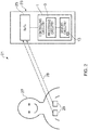
- Fig. 2 schematically illustrates an example system 21 which may be used to implement embodiments of the disclosure.
- the example system 21 comprises a processing device 23 and a plurality of capacitive sensors 29.
- the processing device 23 comprises an apparatus 1 comprising controlling circuitry 3 which may be as described above.
- the memory circuitry 7 comprises a database 13.
- one or more databases 13 may be stored in one or more different devices.
- the processing device 23 may be arranged to communicate with the one or more different devices so as to enable the one or more databases 13 to be accessed as needed.
- the processing device 23 also comprises one or more transceivers 25.
- the transceiver is shown as a single component. It is to be appreciated that separate transmitters and receivers may be provided in some processing devices 23 in other examples of the disclosure.
- the transceiver 25 may comprise any means which enables a communication link 28 to be established between the processing device 23 and the plurality of capacitive sensors 29.
- the transceivers 25 may enable wireless communication links to be established.
- the wireless communication links could be any suitable type of communication links such as Bluetooth, Bluetooth Low Energy, Bluetooth Smart, 6LoWPan (IP v 6 over low power personal area networks) ZigBee, ANT+, Radio frequency identification, wireless local area network (wireless LAN) or any other suitable types of wireless communication links.
- the system 21 also comprises a plurality of capacitive sensors 29.
- capacitive sensors 29 In the example of Fig. 2 two electrodes are shown however it is to be appreciated that any number of capacitive sensors 29 could be used in other examples of the disclosure.
- the capacitive sensors 29 are positioned on the body of a subject 27.
- the subject 27 is a person however examples of the disclosure could also be used for animals.
- the capacitive sensors 29 may be positioned on any suitable location on the subject 27.
- the location of the capacitive sensors 29 may be determined by the biopotential signals that the capacitive sensors 29 are arranged to detect. For instance, where the capacitive sensors 29 are arranged to detect an ECG signal the capacitive sensors 29 may be positioned on the subject's 27 chest and where the capacitive sensors 29 are arranged to detect an EEG signal the capacitive sensors 29 may be positioned on the subject's 27 head.
- the capacitive sensors 29 may comprise any means which may be arranged to capacitively sense a biopotential signal from the subject's body.
- the capacitive sensors 29 may be arranged so that the conductive portions of the capacitive sensors 29 are not in direct electrical contact with the subject's body.
- the capacitive sensors 29 may be wireless capacitive sensors 29. In examples of the disclosure there might be no cables or wires between any of the capacitive sensors 29 on the subject 27. Each of the plurality of capacitive sensors 29 may therefore be standalone capacitive sensors 29 which can operate independently so that each capacitive sensor 29 measures a biopotential signal independently of the other capacitive sensors 29.
- the capacitive sensors 29 may also comprise one or more transceivers which enable the capacitive sensors 29 to establish a wireless communication link between the capacitive sensors 29 and the processing device 23. This enables the system 21 to be arranged without any wires or cables needed to connect the capacitive sensors 29 and processing device 23 together. This may make the system 21 easier and more convenient to use as there are no cables which might restrict the possible positions of the capacitive sensors 29.
- a partially wired system 21 may be used.
- the partially wired system 21 may comprise some wires connecting one or more of the sensors 29 to other components within the system 21.
- the partially wired system 21 might not comprise any wires directly between sensors 21.
- the biopotential signals that are measured by the capacitive sensors 29 may comprise any time varying electrical signal that is generated by the subject 27.
- the biopotential signal may comprise an autonomic signal.
- the autonomic signal may be controlled subconsciously by the subject 27.
- the biopotential signals may comprise electrical signals that are generated within the subject's body by the user's heartbeat.
- the biopotental signals could comprise electrical activity of the user's brain or other parts of their nervous system.
- the biopotential signal could comprise at least one of an electrocardiogram signal, electroencephalogram signal, electromyogram signal, electrooculogram signal, electrogastrogram signal, electonystagmogram signal, skin potential signal or any other suitable biopotential signal.
- the processing device 23 has established a communication link 28 directly with each of the capacitive sensors 29.
- one or more additional devices could be provided between the capacitive sensors 29 and the processing device 23.
- the system could comprise a communication device.
- the capacitive sensors 29 may be arranged to transmit the biopotential signals to the communication device via any suitable means.
- the communication device could then transmit the biopotential signals to the processing device 23.
- the processing device 23 is provided as a separate device to any of the sensors 29.
- Each of the sensors 29 is arranged to provide signals to the processing device 23 via the communication link 28.
- one or more sensors 29 could be provided within the processing device 23.
- the sensors 29 which are not part of the processing device 23 may provide signals via a communication link 28 while the sensors 29 which are provided within the processing device 23 do not need such a communication link 28.
- Fig. 3 illustrates a method for synchronizing biopotential signals that are obtained using the capacitive sensors 29.
- the method may be implemented using apparatus 1 and systems 21 as described above. In some examples the method may be performed by a single processing device 23. In other examples the method mat be performed by two or more distributed processing devices 23.
- the method comprises receiving, at block 31, a first biopotential signal obtained by a first capacitive sensor 29 and at block 33, receiving a second biopotential signal obtained by a second capacitive sensor 29.
- the first capacitive sensor 29 and the second capacitive sensor 29 are positioned at different locations on a subject 27.
- the first capacitive sensor 29 and the second capacitive sensor 29 may be operating independently of each other. There might be no wires or cables connecting the respective capacitive sensors 29.
- the capacitive sensors 29 may be arranged to communicate with the processing device 23 however the capacitive sensors 29 may be arranged so that there is no direct communication between the capacitive sensors 29 themselves.
- the biopotential signals obtained by the first capacitive sensor 29 and the second capacitive sensor 29 are received via wireless communication links 28.
- the processing device 23 may establish a separate communication link 28 with each of the capacitive sensors 29. This may ensure that the respective capacitive sensors 29 can operate independently of each other.
- the method comprises synchronising biopotential signals obtained by the first capacitive sensor 29 and the second capacitive sensor 29 by applying a time adjustment to biopotential signals obtained by at least one of the first capacitive sensor 29 or the second capacitive sensor 29.
- Features in at least one of the first biopotential signal and the second biopotential signal are used to synchronise the biopotential signals obtained by the first capacitive sensor 29 and the second capacitive sensor 29.
- synchronising the biopotential signals comprises determining a delay between the first biopotential signal and the second biopotential signal.
- the delay may be calculated or estimated and information indicative of the delay may be stored in the memory circuitry 7. The information indicative of the delay can then be retrieved when needed to synchronise biopotential signals obtained by the capacitive sensors 29.
- the process of determining the delay may comprise cross collating the respective biopotential signals and comparing the delay between features in the signals.
- the features could comprise features of the biopotential signals. For example they could comprise the distinctive maxima and minima of an ECG signal. In some examples the features could comprise noise that is present in all of the bio potential signals obtained by the capacitive sensors 29.
- biopotential signals could be synchronised without explicitly calculating or estimating the delay.
- synchronising the biopotential signals comprises combining the first biopotential signal and the second biopotential signal and adjusting the time alignment of the biopotential signals to provide a combined signal comprising identifiable features.
- the identifiable features may comprise any features within the signals that can be recognised by the processing circuitry 5.
- the identifiable features may comprise any suitable patterns, shape or sequences within the biopotential signals
- a machine learning process may be used to recognise the identifiable features.
- the machine learning process may comprise retrieving information stored in one or more databases 13 and comparing the combined biopotential signals with the retrieved information.
- the combined biopotential signals may be considered to be synchronised when the combined signals correspond to the retrieved information.
- the combined biopotential signals may correspond to the retrieved information when one or more identifiable features in the combined signals match, or are similar to features from signals stored in the database 13.
- the biopotential signals that are synchronised comprise the first biopotential signal and the second biopotential signal.
- the first biopotential signal and the second biopotential signal may be stored in the memory circuitry and may be synchronised by the processing device 23.
- the synchronisation may be performed in real time. For example, it may be performed by the processing device 23 while the capacitive sensors 29 are obtaining biopotential signals from the user and transmitting these to the processing device 23. This may enable the synchronised output signals to be provided immediately or with a very small delay. In other examples the synchronisation may be performed at a later time.
- the biopotential signals that are synchronised comprise further biopotential signals detected by the first capacitive sensor 29 and the second capacitive sensor 29.
- the first biopotential signal and the second biopotential signal may be used to calibrate the system 21 and determine how the synchronisation should be performed. Once the system 21 has been calibrated the capacitive sensors 29 may then be used to obtain further biopotential signals which can then be synchronised as required.
- one or more of the capacitive sensors 29 may be moved between the block 31 of obtaining the calibration biopotential signals and the block 33 of obtaining the further biopotential signals.
- the capacitive sensors 29 may be positioned on the torso of a subject 27 and then the capacitive sensor 29 could be positioned on the subject's 27 head to obtain the further biopotential signals.
- the calibration biopotential signals and the further biopotential signals may comprise information about different types of biopotentials.
- the calibration biopotential signals may comprise signals that comprise distinctive features that can be easily recognised by the processing circuitry 5 while the further biopotential signals may comprise features that are not as easily recognised by the processing circuitry 5.
- the first biopotential signal and the second biopotential signal that are used as the calibration signals could comprise ECG signals and the further biopotential signals could comprise electrooculogram (EOG) signals or vice versa.
- ECG electrooculogram
- Other types of biopotential signals could comprise electroencephalogram signals, electronystagmogram signals, electromyogram signals, electroneurogram signals, or skin potentials or other types of signals.
- the biopotential signals may be processed.
- the processing may be performed by the processing circuitry 5 of the processing device 23.
- the biopotential signals may be transmitted to one or more other processing devices 23 to enable the processing to be performed.
- the processing may comprise removing noise from one or more of the biopotential signals and/or reconstructing at least part of the one or more biopotential signals and/or any other suitable processing.
- the reconstruction of the biopotential signals may comprise any suitable method which enables a partial signal to be reconstructed.
- a machine learning process may be used to enable the reconstruction of at least part of the biopotential signals.
- the processing circuitry 5 may use signals that are stored in the database 13 to enable the missing segments of the obtained biopotential signals to be identified and reconstructed.
- the processing of the biopotential signals may enable feedback to be provided to the subject 27 or another user of the system 21 such as a medical professional. For instance, if the biopotential signals comprise information indicative of the user's heart rate then the processing of the signal may enable information indicative of the heart rate to be provided. In some examples the system 21 may be arranged to give a warning output if the heart rate drops outside of a threshold frequency band.
- the method comprises receiving two biopotential signals from two capacitive sensors 29. It is to be appreciated that in implementations of the disclosure the method may comprise receiving the biopotential signals from more than two capacitive sensors 29. For example a plurality of capacitive sensors 29 may be positioned at a plurality of different locations on the subject 27. Each of the capacitive sensors 29 may be operating independently of the other capacitive sensors 29 so that there is no direct communication between any of the capacitive sensors 29.
- one or more of the capacitive sensors 29 may act as a gateway for one or more other capacitive sensors 29 within the system 21.
- a communication link may be established between a first capacitive sensor 29 and a second capacitive sensor 29. This may enable information to be provided from the first capacitive sensor 29 to the second capacitive sensor 29.
- the second capacitive sensor 29 may then use a communication link 28 to transmit the information to a processing device 23.
- the processing device 23 may be arranged to provide control signals to one or more of the capacitive sensors 29.
- the processing device 23 may provide the control signals via the wireless communication links 28.
- the control signals may control the time periods for which the capacitive sensors 29 are active. This may enable different capacitive sensors 29 to be active for different time periods. For example a first control signal, provided to a first capacitive sensor 29, may cause the first capacitive sensor 29 to be active for a first time period and inactive for a second time period while a second control signal, provided to a second capacitive sensor 29, may cause the second capacitive sensor 29 to be inactive for the first time period and active for the second time period.
- a machine learning algorithm may be used to reconstruct the signals to correct for the time periods where the capacitive sensors 29 are inactive.
- Having different capacitive sensors 29 active at different times may provide for a more efficient sensing system 21 because it reduces the power requirements of the system. Having reduced power requirements may also enable the capacitive sensors 29 to be worn for a longer period of time and so may enable the information about the biopotential signals to be obtained over longer periods of time. This may also reduce the amount of data that is collected and so reduces the bandwidth required for the communication links 28 and may reduce the processing requirements and/or memory requirements for the processing device 23.
- control signals may also allow for adaptive operation of the capacitive sensors 29.
- the processing device 23 may be arranged to determine optimal operating variables for the capacitive sensors 29 and transmit these to the capacitive sensors 29 via the communication links 28.
- the operative variables that are controlled by the control signals could comprise the filters used, the gain applied or any other suitable variables.
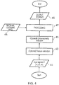
- Fig. 4 illustrates another method which may be implemented using apparatus 1 and systems 21 as described.
- a plurality of biopotential signals are received.
- n biopotential signals are received.
- the n biopotential signals may be received from n capacitive sensors 29 which may be as described above.
- Each of the biopotential signals may comprise time as one of the dimensions.
- the method comprises synchronizing the received biopotential signals.
- the received biopotential signals could be synchronized using any suitable method.
- the biopotential signals may be synchronized by extracting features in the received biopotential signals and using these extracted features to determine the time delay.
- the biopotential signals can then be synchronized by adding the suitable delay to the respective biopotential signals.
- the method comprises dimensionality reduction.
- the dimensionality reduction may ensure that the dimensionality of the output signals is fixed for any number of input biopotential signals.
- the dimensionality reduction may be implemented using principal components analysis, independent components analysis, singular value decomposition, machine learning or any other suitable process.
- the processing performed at block 47 comprises reducing the noise in the synchronized biopotential signal.
- the noise that is present in the received biopotential signals could comprise noise caused by internal sources and/or noise caused by external sources.
- the internal sources may be internal to the body of the subject 27.
- the internal sources of noise could be caused by motion of the subject 27, muscle signals, poor electrical connection between the capacitive sensors 29 and the subject 27 or any other suitable source.
- the external sources of noise could be caused by powerline noise or any other suitable source.
- the processing may comprise machine learning processes.
- the machine learning process may enable the biopotential signals to be retrieved from noisy and/or partial signals. This may require machine learning information to be obtained from one or more databases 13.
- the machine learning information 48 that is retrieved from the one or more databases may comprise information 48 that has been obtained from a plurality of subjects 27.
- the machine learning information 48 may comprise a high quality signal.
- the high quality signal could be obtained using a different system 21 to the one used to obtain the biopotential signals in examples of the disclosure.
- the high quality signal could be obtained using a more reliable and less noisy system.
- the information from the high quality signals can be used to reconstruct the noisy and/or partial biosignals obtained from the capacitive sensors 29.
- the machine learning information 48 may be obtained from the same subject 27 being currently monitored. In some examples the machine learning information 48 could also comprise, or alternatively comprises, data obtained from one or more other subjects. The machine learning information 48 may be determined by using corresponding pairs of input signal and output signal examples to obtain a generalized mapping between them.
- the machine learning process may be implemented using fully connected, recurrent or one dimensional convolutional neural network or by using support vector machines using features obtained by discrete cosine transforms, fast Fourier transforms or wavelets or by using any other suitable process.
- deep convolutional neural networks can be used as a model between input signals and output signals.
- the machine learning can be trained using any variant of stochastic gradient descent, where random corresponding pairs of input and output data are shown sequentially to the machine learning training process.
- the machine learning training process then computes a predicted output and error between predicted output and target output.
- error gradients may then be computed with regards to the neural networks weights, and then the weights are adjusted in order to minimize the error between target output and the predicted output.
- the machine learning training process continues until the model converges or some other external criteria is met. After training, the machine learning process can be used for prediction.
- the machine learning process may also comprise calculating a confidence estimate. This may provide an indication of the amount of error in the processed signal.
- an output signal is obtained.
- the output signal is the synchronized biopotential signals.
- the output signals may comprise a signal derived from the synchronized biopotential signals.
- the input biopotential signal could comprise an ECG signal and the output signal could comprise the subject's heart rate or heart rate variability.
- each of the capacitive sensors 29 may have the same clock speed, however, as the capacitive sensors 29 are operating independently of each other different capacitive sensors 29 may have different reference times.
- the above described examples enable the reference times to be synchronised by post-processing.
- the capacitive sensors 29 could have different clock speeds.
- additional processes may be used to account for the differences in clock speeds.
- dynamic time warping distance based methods or machine learning processes may be used to enable the time alignment between the different capacitive sensors 29.
- a technical effect of one or more examples described herein is providing a wireless system 21 which can be used to monitor biopotential signals from a subject.
- the system is wireless 21 this means that the capacitive sensors 29 can be positioned on any suitable location on the subject. This may enable different types of biopotential signals to be monitored. This may also allow freedom of movement for the subject 27 while the biopotential signals are being measured.
- Examples of the disclosure may also enable different types of data to be extracted from biopotential signals. For instance in some examples it may enable both ECG and EOG data to be extracted from the same biopotential signals. This may allow for improved medical diagnostics which may reduce the number of capacitive sensors 29 needed and/or the amount of tests that are required on the subject 27.
- coupled means operationally coupled and any number or combination of intervening elements can exist between coupled components (including no intervening elements).
- example or “for example” or “may” in the text denotes, whether explicitly stated or not, that such features or functions are present in at least the described example, whether described as an example or not, and that they can be, but are not necessarily, present in some of or all other examples.
- example “for example” or “may” refers to a particular instance in a class of examples.
- a property of the instance can be a property of only that instance or a property of the class or a property of a subclass of the class that includes some but not all of the instances in the class. It is therefore implicitly disclosed that a feature described with reference to one example but not with reference to another example, can where possible be used in that other example but does not necessarily have to be used in that other example.
Landscapes
- Health & Medical Sciences (AREA)
- Life Sciences & Earth Sciences (AREA)
- Engineering & Computer Science (AREA)
- Animal Behavior & Ethology (AREA)
- Public Health (AREA)
- Pathology (AREA)
- Physics & Mathematics (AREA)
- Biomedical Technology (AREA)
- Heart & Thoracic Surgery (AREA)
- Medical Informatics (AREA)
- Molecular Biology (AREA)
- Surgery (AREA)
- Veterinary Medicine (AREA)
- General Health & Medical Sciences (AREA)
- Biophysics (AREA)
- Physiology (AREA)
- Signal Processing (AREA)
- Psychiatry (AREA)
- Artificial Intelligence (AREA)
- Computer Vision & Pattern Recognition (AREA)
- Cardiology (AREA)
- Microelectronics & Electronic Packaging (AREA)
- Computer Networks & Wireless Communication (AREA)
- Measurement And Recording Of Electrical Phenomena And Electrical Characteristics Of The Living Body (AREA)
- Psychology (AREA)
- Ophthalmology & Optometry (AREA)
Abstract
Description
- Examples of the disclosure relate to a method, apparatus and computer program for synchronizing biopotential signals. In particular they relate to a method, apparatus and computer program for synchronizing biopotential signals obtained by a plurality of capacitive sensors.
- Capacitive sensors can be used to detect biopotential signals such as ECG (electrocardiogram) or EEG (electroencephalogram) signals. Such sensing systems may comprise a plurality of sensors which may be positioned at different locations on a subject's body.
- According to various, but not necessarily all, examples of the disclosure there may be provided a method comprising: receiving a first biopotential signal obtained by a first capacitive sensor; receiving a second biopotential signal obtained by a second capacitive sensor, the first capacitive sensor and the second capacitive sensor being positioned at different locations on a subject; synchronising biopotential signals obtained by the first capacitive sensor and the second capacitive sensor by applying a time adjustment to biopotential signals obtained by at least one of the first capacitive sensor or the second capacitive sensor; wherein features in at least one of the first biopotential signal and the second biopotential signal are used to synchronise the biopotential signals obtained by the first capacitive sensor and the second capacitive sensor.
- Synchronising the biopotential signals may comprise determining a delay between the first biopotential signal and the second biopotential signal.
- Synchronising the biopotential signals may comprise combining the first biopotential signal and the second biopotential signal and adjusting the time alignment of the biopotential signals to provide a combined signal comprising features. The method may comprise using a machine learning process to recognise the identifiable features.
- The biopotential signals that are synchronised may comprise the first biopotential signal and the second biopotential signal.
- The biopotential signals that are synchronised comprise further biopotential signals detected by the first capacitive sensor and the second capacitive sensor. The first biopotential signal and the second biopotential signal may comprise information indicative of a first type of biopotential and the further biopotential signals detected by the first capacitive sensor and the second capacitive sensor comprise information indicative of a second different type of biopotential. The first biopotential signal and the second biopotential signal may comprise electrocardiogram signals and the further biopotential signals comprise at least one of; electroencephalogram signals , electro-oculogram signals, electronystagmogram signals, electromyogram signals, electroneurogram signals, or skin potentials.
- The method may comprise causing processing of the synchronised biopotential signals wherein the processing comprises at least one of; removing noise from one or more of the biopotential signals, reconstructing at least part of the one or more biopotential signals. The machine learning process may be used to reconstruct at least part of the one or more biopotential signals.
- The biopotential signals obtained by the first capacitive sensor and the second capacitive sensor may be received via wireless communication links.
- The biopotential signals may be obtained from more than two capacitive sensors
- The method may comprise providing a control signal for at least one of the capacitive sensors wherein the control signal causes the at least one capacitive sensor to be active for a first time period and inactive for a second time period.
- The method may comprise providing control signals to the capacitive sensors so that different capacitive sensors are arranged to detect the biopotentials at different times.
- According to various, but not necessarily all, examples of the disclosure there may be provided an apparatus comprising: means for receiving a first biopotential signal obtained by a first capacitive sensor; means for receiving a second biopotential signal obtained by a second capacitive sensor, the first capacitive sensor and the second capacitive sensor being positioned at different locations on a subject; means for synchronising biopotential signals obtained by the first capacitive sensor and the second capacitive sensor by applying a time adjustment to biopotential signals obtained by at least one of the first capacitive sensor or the second capacitive sensor; wherein features in at least one of the first biopotential signal and the second biopotential signal are used to synchronise the biopotential signals obtained by the first capacitive sensor and the second capacitive sensor.
- According to various, but not necessarily all, examples of the disclosure there may be provided an apparatus comprising: processing circuitry; and memory circuitry including computer program code, the memory circuitry and the computer program code configured to, with the processing circuitry, cause the apparatus to: receive a first biopotential signal obtained by a first capacitive sensor; receive a second biopotential signal obtained by a second capacitive sensor, the first capacitive sensor and the second capacitive sensor being positioned at different locations on a subject; synchronise biopotential signals obtained by the first capacitive sensor and the second capacitive sensor by applying a time adjustment to biopotential signals obtained by at least one of the first capacitive sensor or the second capacitive sensor; wherein features in at least one of the first biopotential signal and the second biopotential signal are used to synchronise the biopotential signals obtained by the first capacitive sensor and the second capacitive sensor.
- According to various, but not necessarily all, examples of the disclosure there may be provided a computer program comprising computer program instructions that, when executed by processing circuitry, causes receiving a first biopotential signal obtained by a first capacitive sensor; receiving a second biopotential signal obtained by a second capacitive sensor, the first capacitive sensor and the second capacitive sensor being positioned at different locations on a subject; synchronising biopotential signals obtained by the first capacitive sensor and the second capacitive sensor by applying a time adjustment to biopotential signals obtained by at least one of the first capacitive sensor or the second capacitive sensor; wherein features in at least one of the first biopotential signal and the second biopotential signal are used to synchronise the biopotential signals obtained by the first capacitive sensor and the second capacitive sensor.
- According to various, but not necessarily all, examples of the disclosure there are provided examples as claimed in the appended claims.
- For a better understanding of various examples that are useful for understanding the detailed description, reference will now be made by way of example only to the accompanying drawings in which:
-
Fig. 1 illustrates an apparatus; -
Fig. 2 illustrates a system; -
Fig. 3 illustrates a method; and -
Fig. 4 illustrates another method. - Examples of the disclosure relate to methods, apparatus and computer programs which may be used to synchronize biopotential signals obtained from capacitive electrodes. The methods, apparatus and computer programs and computer programs can be used with wireless electrodes. The wireless electrodes may be easier and more convenient to attach to a subject than electrodes which are coupled together by one or more wires or cables.
-
Fig. 1 schematically illustrates anapparatus 1 which may be used to implement examples of the disclosure. - The
apparatus 1 illustrated inFig. 1 may be a chip, a chip-set or any other suitable arrangement. In some examples theapparatus 1 may be provided within any suitable device such as a processing device or a communications device. - The
apparatus 1 comprises controllingcircuitry 3. The controllingcircuitry 3 may provide means for controlling an electronic device such as processing device or a communications device. The controllingcircuitry 3 may also provide means for performing the methods, or at least part of the methods, of examples of the disclosure. - The controlling
circuitry 3 comprises processing circuitry 5 andmemory circuitry 7. The processing circuitry 5 may be configured to read from and write to thememory circuitry 7. The processing circuitry 5 may comprise one or more processors. The processing circuitry 5 may also comprise an output interface via which data and/or commands are output by the processing circuitry 5 and an input interface via which data and/or commands are input to the processing circuitry 5. - The
memory circuitry 7 may be configured to store a computer program 9 comprising computer program instructions (computer program code 11) that controls the operation of theapparatus 1 when loaded into processing circuitry 5. The computer program instructions, of the computer program 9, provide the logic and routines that enable theapparatus 1 to perform the example methods described. The processing circuitry 5 by reading thememory circuitry 7 is able to load and execute the computer program 9. - In examples of the disclosure the
memory circuitry 7 is arranged to store one ormore databases 13. Thedatabases 13 may be used to store information that can be used to enable a plurality of biopotential signals to be synchronised. In some examples thedatabases 13 may comprise reference signals that can be compared to biopotential signals obtained by a plurality of capacitive electrodes to enable the biopotential signals to be synchronised. The information stored in thedatabases 13 may comprise information which enables a machine learning algorithm to be used to synchronise the biopotential signals. - The computer program 9 may arrive at the
apparatus 1 via any suitable delivery mechanism. The delivery mechanism may be, for example, a non-transitory computer-readable storage medium, a computer program product, a memory device, a record medium such as a compact disc read-only memory (CD-ROM) or digital versatile disc (DVD), or an article of manufacture that tangibly embodies the computer program. The delivery mechanism may be a signal configured to reliably transfer the computer program 9. The apparatus may propagate or transmit the computer program 9 as a computer data signal. In some examples thecomputer program code 11 may be transmitted to theapparatus 1 using a wireless protocol such as Bluetooth, Bluetooth Low Energy, Bluetooth Smart, 6LoWPan (IPv6 over low power personal area networks) ZigBee, ANT+, near field communication (NFC), Radio frequency identification, wireless local area network (wireless LAN) or any other suitable protocol. - Although the
memory circuitry 7 is illustrated as a single component in the figures it is to be appreciated that it may be implemented as one or more separate components some or all of which may be integrated/removable and/or may provide permanent/semi-permanent/dynamic/cached storage. - Although the processing circuitry 5 is illustrated as a single component in the figures it is to be appreciated that it may be implemented as one or more separate components some or all of which may be integrated/removable.
- References to "computer-readable storage medium", "computer program product", "tangibly embodied computer program" etc. or a "controller", "computer", "processor" etc. should be understood to encompass not only computers having different architectures such as single/multi-processor architectures, Reduced Instruction Set Computing (RISC) and sequential (Von Neumann)/parallel architectures but also specialized circuits such as field-programmable gate arrays (FPGA), application-specific integrated circuits (ASIC), signal processing devices and other processing circuitry. References to computer program, instructions, code etc. should be understood to encompass software for a programmable processor or firmware such as, for example, the programmable content of a hardware device whether instructions for a processor, or configuration settings for a fixed-function device, gate array or programmable logic device etc.
- As used in this application, the term "circuitry" refers to all of the following:
- (a) hardware-only circuit implementations (such as implementations in only analog and/or digital circuitry) and
- (b) to combinations of circuits and software (and/or firmware), such as (as applicable): (i) to a combination of processor(s) or (ii) to portions of processor(s)/software (including digital signal processor(s)), software, and memory(ies) that work together to cause an apparatus, such as a mobile phone or server, to perform various functions) and
- (c) to circuits, such as a microprocessor(s) or a portion of a microprocessor(s), that require software or firmware for operation, even if the software or firmware is not physically present.
- This definition of "circuitry" applies to all uses of this term in this application, including in any claims. As a further example, as used in this application, the term "circuitry" would also cover an implementation of merely a processor (or multiple processors) or portion of a processor and its (or their) accompanying software and/or firmware. The term "circuitry" would also cover, for example and if applicable to the particular claim element, a baseband integrated circuit or applications processor integrated circuit for a mobile phone or a similar integrated circuit in a server, a cellular network device, or other network device.
-
Fig. 2 schematically illustrates an example system 21 which may be used to implement embodiments of the disclosure. The example system 21 comprises aprocessing device 23 and a plurality ofcapacitive sensors 29. - The
processing device 23 comprises anapparatus 1 comprising controllingcircuitry 3 which may be as described above. In the example ofFig. 2 thememory circuitry 7 comprises adatabase 13. In other examples one ormore databases 13 may be stored in one or more different devices. Theprocessing device 23 may be arranged to communicate with the one or more different devices so as to enable the one ormore databases 13 to be accessed as needed. - The
processing device 23 also comprises one ormore transceivers 25. In the example ofFig. 2 the transceiver is shown as a single component. It is to be appreciated that separate transmitters and receivers may be provided in someprocessing devices 23 in other examples of the disclosure. - The
transceiver 25 may comprise any means which enables acommunication link 28 to be established between theprocessing device 23 and the plurality ofcapacitive sensors 29. Thetransceivers 25 may enable wireless communication links to be established. The wireless communication links could be any suitable type of communication links such as Bluetooth, Bluetooth Low Energy, Bluetooth Smart, 6LoWPan (IPv6 over low power personal area networks) ZigBee, ANT+, Radio frequency identification, wireless local area network (wireless LAN) or any other suitable types of wireless communication links. - The system 21 also comprises a plurality of
capacitive sensors 29. In the example ofFig. 2 two electrodes are shown however it is to be appreciated that any number ofcapacitive sensors 29 could be used in other examples of the disclosure. - The
capacitive sensors 29 are positioned on the body of a subject 27. In the example ofFig, 2 the subject 27 is a person however examples of the disclosure could also be used for animals. Thecapacitive sensors 29 may be positioned on any suitable location on the subject 27. The location of thecapacitive sensors 29 may be determined by the biopotential signals that thecapacitive sensors 29 are arranged to detect. For instance, where thecapacitive sensors 29 are arranged to detect an ECG signal thecapacitive sensors 29 may be positioned on the subject's 27 chest and where thecapacitive sensors 29 are arranged to detect an EEG signal thecapacitive sensors 29 may be positioned on the subject's 27 head. - The
capacitive sensors 29 may comprise any means which may be arranged to capacitively sense a biopotential signal from the subject's body. Thecapacitive sensors 29 may be arranged so that the conductive portions of thecapacitive sensors 29 are not in direct electrical contact with the subject's body. - The
capacitive sensors 29 may be wirelesscapacitive sensors 29. In examples of the disclosure there might be no cables or wires between any of thecapacitive sensors 29 on the subject 27. Each of the plurality ofcapacitive sensors 29 may therefore be standalonecapacitive sensors 29 which can operate independently so that eachcapacitive sensor 29 measures a biopotential signal independently of the othercapacitive sensors 29. - The
capacitive sensors 29 may also comprise one or more transceivers which enable thecapacitive sensors 29 to establish a wireless communication link between thecapacitive sensors 29 and theprocessing device 23. This enables the system 21 to be arranged without any wires or cables needed to connect thecapacitive sensors 29 andprocessing device 23 together. This may make the system 21 easier and more convenient to use as there are no cables which might restrict the possible positions of thecapacitive sensors 29. In other examples a partially wired system 21 may be used. The partially wired system 21 may comprise some wires connecting one or more of thesensors 29 to other components within the system 21. The partially wired system 21 might not comprise any wires directly between sensors 21. - The biopotential signals that are measured by the
capacitive sensors 29 may comprise any time varying electrical signal that is generated by the subject 27. The biopotential signal may comprise an autonomic signal. The autonomic signal may be controlled subconsciously by the subject 27. In some examples the biopotential signals may comprise electrical signals that are generated within the subject's body by the user's heartbeat. In some examples the biopotental signals could comprise electrical activity of the user's brain or other parts of their nervous system. The biopotential signal could comprise at least one of an electrocardiogram signal, electroencephalogram signal, electromyogram signal, electrooculogram signal, electrogastrogram signal, electonystagmogram signal, skin potential signal or any other suitable biopotential signal. - In the example system 21 of
Fig. 2 theprocessing device 23 has established acommunication link 28 directly with each of thecapacitive sensors 29. In this example there are no intervening elements between thecapacitive sensors 29 and theprocessing device 23. In other examples, one or more additional devices could be provided between thecapacitive sensors 29 and theprocessing device 23. For instance the system could comprise a communication device. Thecapacitive sensors 29 may be arranged to transmit the biopotential signals to the communication device via any suitable means. The communication device could then transmit the biopotential signals to theprocessing device 23. - In the example of
Fig. 2 theprocessing device 23 is provided as a separate device to any of thesensors 29. Each of thesensors 29 is arranged to provide signals to theprocessing device 23 via thecommunication link 28. In other examples one ormore sensors 29 could be provided within theprocessing device 23. In such examples thesensors 29 which are not part of theprocessing device 23 may provide signals via acommunication link 28 while thesensors 29 which are provided within theprocessing device 23 do not need such acommunication link 28. -
Fig. 3 illustrates a method for synchronizing biopotential signals that are obtained using thecapacitive sensors 29. The method may be implemented usingapparatus 1 and systems 21 as described above. In some examples the method may be performed by asingle processing device 23. In other examples the method mat be performed by two or more distributedprocessing devices 23. - The method comprises receiving, at
block 31, a first biopotential signal obtained by afirst capacitive sensor 29 and atblock 33, receiving a second biopotential signal obtained by asecond capacitive sensor 29. Thefirst capacitive sensor 29 and thesecond capacitive sensor 29 are positioned at different locations on a subject 27. - The
first capacitive sensor 29 and thesecond capacitive sensor 29 may be operating independently of each other. There might be no wires or cables connecting the respectivecapacitive sensors 29. Thecapacitive sensors 29 may be arranged to communicate with theprocessing device 23 however thecapacitive sensors 29 may be arranged so that there is no direct communication between thecapacitive sensors 29 themselves. - In examples of the disclosure the biopotential signals obtained by the
first capacitive sensor 29 and thesecond capacitive sensor 29 are received via wireless communication links 28. In examples of the disclosure theprocessing device 23 may establish aseparate communication link 28 with each of thecapacitive sensors 29. This may ensure that the respectivecapacitive sensors 29 can operate independently of each other. - At
block 35 the method comprises synchronising biopotential signals obtained by thefirst capacitive sensor 29 and thesecond capacitive sensor 29 by applying a time adjustment to biopotential signals obtained by at least one of thefirst capacitive sensor 29 or thesecond capacitive sensor 29. Features in at least one of the first biopotential signal and the second biopotential signal are used to synchronise the biopotential signals obtained by thefirst capacitive sensor 29 and thesecond capacitive sensor 29. - Other suitable processes may be used to synchronise the biopotential signals. In some examples synchronising the biopotential signals comprises determining a delay between the first biopotential signal and the second biopotential signal. In such examples the delay may be calculated or estimated and information indicative of the delay may be stored in the
memory circuitry 7. The information indicative of the delay can then be retrieved when needed to synchronise biopotential signals obtained by thecapacitive sensors 29. - Other suitable methods may be used to determine the delay between the respective biopotential signals. In some examples the process of determining the delay may comprise cross collating the respective biopotential signals and comparing the delay between features in the signals. The features could comprise features of the biopotential signals. For example they could comprise the distinctive maxima and minima of an ECG signal. In some examples the features could comprise noise that is present in all of the bio potential signals obtained by the
capacitive sensors 29. - In some examples the biopotential signals could be synchronised without explicitly calculating or estimating the delay. For instance, in some examples synchronising the biopotential signals comprises combining the first biopotential signal and the second biopotential signal and adjusting the time alignment of the biopotential signals to provide a combined signal comprising identifiable features. The identifiable features may comprise any features within the signals that can be recognised by the processing circuitry 5. For example, the identifiable features may comprise any suitable patterns, shape or sequences within the biopotential signals
- In such examples a machine learning process may be used to recognise the identifiable features. The machine learning process may comprise retrieving information stored in one or
more databases 13 and comparing the combined biopotential signals with the retrieved information. The combined biopotential signals may be considered to be synchronised when the combined signals correspond to the retrieved information. The combined biopotential signals may correspond to the retrieved information when one or more identifiable features in the combined signals match, or are similar to features from signals stored in thedatabase 13. - In some examples the biopotential signals that are synchronised comprise the first biopotential signal and the second biopotential signal. For instance the first biopotential signal and the second biopotential signal may be stored in the memory circuitry and may be synchronised by the
processing device 23. The synchronisation may be performed in real time. For example, it may be performed by theprocessing device 23 while thecapacitive sensors 29 are obtaining biopotential signals from the user and transmitting these to theprocessing device 23. This may enable the synchronised output signals to be provided immediately or with a very small delay. In other examples the synchronisation may be performed at a later time. - In some examples the biopotential signals that are synchronised comprise further biopotential signals detected by the
first capacitive sensor 29 and thesecond capacitive sensor 29. For example, the first biopotential signal and the second biopotential signal may be used to calibrate the system 21 and determine how the synchronisation should be performed. Once the system 21 has been calibrated thecapacitive sensors 29 may then be used to obtain further biopotential signals which can then be synchronised as required. - In some examples one or more of the
capacitive sensors 29 may be moved between theblock 31 of obtaining the calibration biopotential signals and theblock 33 of obtaining the further biopotential signals. For instance, to obtain the calibration biopotential signals thecapacitive sensors 29 may be positioned on the torso of a subject 27 and then thecapacitive sensor 29 could be positioned on the subject's 27 head to obtain the further biopotential signals. - In some examples the calibration biopotential signals and the further biopotential signals may comprise information about different types of biopotentials. In some examples the calibration biopotential signals may comprise signals that comprise distinctive features that can be easily recognised by the processing circuitry 5 while the further biopotential signals may comprise features that are not as easily recognised by the processing circuitry 5. For instance the first biopotential signal and the second biopotential signal that are used as the calibration signals could comprise ECG signals and the further biopotential signals could comprise electrooculogram (EOG) signals or vice versa. It is to be appreciated that other types of biopotential signals could be used in other examples of the disclosure. Other types of biopotential signals could comprise electroencephalogram signals, electronystagmogram signals, electromyogram signals, electroneurogram signals, or skin potentials or other types of signals.
- In some examples of the disclosure once the biopotential signals have been synchronised they may be processed. The processing may be performed by the processing circuitry 5 of the
processing device 23. In some examples the biopotential signals may be transmitted to one or moreother processing devices 23 to enable the processing to be performed. The processing may comprise removing noise from one or more of the biopotential signals and/or reconstructing at least part of the one or more biopotential signals and/or any other suitable processing. - The reconstruction of the biopotential signals may comprise any suitable method which enables a partial signal to be reconstructed. In some examples a machine learning process may be used to enable the reconstruction of at least part of the biopotential signals. In such examples the processing circuitry 5 may use signals that are stored in the
database 13 to enable the missing segments of the obtained biopotential signals to be identified and reconstructed. - In some examples the processing of the biopotential signals may enable feedback to be provided to the subject 27 or another user of the system 21 such as a medical professional. For instance, if the biopotential signals comprise information indicative of the user's heart rate then the processing of the signal may enable information indicative of the heart rate to be provided. In some examples the system 21 may be arranged to give a warning output if the heart rate drops outside of a threshold frequency band.
- In the example method described above the method comprises receiving two biopotential signals from two
capacitive sensors 29. It is to be appreciated that in implementations of the disclosure the method may comprise receiving the biopotential signals from more than twocapacitive sensors 29. For example a plurality ofcapacitive sensors 29 may be positioned at a plurality of different locations on the subject 27. Each of thecapacitive sensors 29 may be operating independently of the othercapacitive sensors 29 so that there is no direct communication between any of thecapacitive sensors 29. - In some examples one or more of the
capacitive sensors 29 may act as a gateway for one or more othercapacitive sensors 29 within the system 21. For example a communication link may be established between afirst capacitive sensor 29 and asecond capacitive sensor 29. This may enable information to be provided from thefirst capacitive sensor 29 to thesecond capacitive sensor 29. Thesecond capacitive sensor 29 may then use acommunication link 28 to transmit the information to aprocessing device 23. - In some examples the
processing device 23 may be arranged to provide control signals to one or more of thecapacitive sensors 29. Theprocessing device 23 may provide the control signals via the wireless communication links 28. The control signals may control the time periods for which thecapacitive sensors 29 are active. This may enable differentcapacitive sensors 29 to be active for different time periods. For example a first control signal, provided to afirst capacitive sensor 29, may cause thefirst capacitive sensor 29 to be active for a first time period and inactive for a second time period while a second control signal, provided to asecond capacitive sensor 29, may cause thesecond capacitive sensor 29 to be inactive for the first time period and active for the second time period. This enables differentcapacitive sensors 29 to detect the biopotential signals at different times. In such examples a machine learning algorithm may be used to reconstruct the signals to correct for the time periods where thecapacitive sensors 29 are inactive. - Having different
capacitive sensors 29 active at different times may provide for a more efficient sensing system 21 because it reduces the power requirements of the system. Having reduced power requirements may also enable thecapacitive sensors 29 to be worn for a longer period of time and so may enable the information about the biopotential signals to be obtained over longer periods of time. This may also reduce the amount of data that is collected and so reduces the bandwidth required for the communication links 28 and may reduce the processing requirements and/or memory requirements for theprocessing device 23. - In some examples the control signals may also allow for adaptive operation of the
capacitive sensors 29. For example, theprocessing device 23 may be arranged to determine optimal operating variables for thecapacitive sensors 29 and transmit these to thecapacitive sensors 29 via the communication links 28. The operative variables that are controlled by the control signals could comprise the filters used, the gain applied or any other suitable variables. -
Fig. 4 illustrates another method which may be implemented usingapparatus 1 and systems 21 as described. - At block 41 a plurality of biopotential signals are received. In the example method of
Fig. 4 n biopotential signals are received. The n biopotential signals may be received fromn capacitive sensors 29 which may be as described above. Each of the biopotential signals may comprise time as one of the dimensions. - At
block 43 the method comprises synchronizing the received biopotential signals. The received biopotential signals could be synchronized using any suitable method. In the example method ofFig. 4 the biopotential signals may be synchronized by extracting features in the received biopotential signals and using these extracted features to determine the time delay. The biopotential signals can then be synchronized by adding the suitable delay to the respective biopotential signals. - At
block 45 the method comprises dimensionality reduction. The dimensionality reduction may ensure that the dimensionality of the output signals is fixed for any number of input biopotential signals. The dimensionality reduction may be implemented using principal components analysis, independent components analysis, singular value decomposition, machine learning or any other suitable process. - At
block 47 the synchronized biopotential signals are processed. - In some examples the processing performed at
block 47 comprises reducing the noise in the synchronized biopotential signal. The noise that is present in the received biopotential signals could comprise noise caused by internal sources and/or noise caused by external sources. The internal sources may be internal to the body of the subject 27. The internal sources of noise could be caused by motion of the subject 27, muscle signals, poor electrical connection between thecapacitive sensors 29 and the subject 27 or any other suitable source. The external sources of noise could be caused by powerline noise or any other suitable source. - In the example method of
Fig. 4 the processing may comprise machine learning processes. In such examples the machine learning process may enable the biopotential signals to be retrieved from noisy and/or partial signals. This may require machine learning information to be obtained from one ormore databases 13. Themachine learning information 48 that is retrieved from the one or more databases may compriseinformation 48 that has been obtained from a plurality ofsubjects 27. In some examples themachine learning information 48 may comprise a high quality signal. The high quality signal could be obtained using a different system 21 to the one used to obtain the biopotential signals in examples of the disclosure. The high quality signal could be obtained using a more reliable and less noisy system. The information from the high quality signals can be used to reconstruct the noisy and/or partial biosignals obtained from thecapacitive sensors 29. - In some examples the
machine learning information 48 may be obtained from thesame subject 27 being currently monitored. In some examples themachine learning information 48 could also comprise, or alternatively comprises, data obtained from one or more other subjects. Themachine learning information 48 may be determined by using corresponding pairs of input signal and output signal examples to obtain a generalized mapping between them. - The machine learning process may be implemented using fully connected, recurrent or one dimensional convolutional neural network or by using support vector machines using features obtained by discrete cosine transforms, fast Fourier transforms or wavelets or by using any other suitable process.
- For instance deep convolutional neural networks can be used as a model between input signals and output signals. The machine learning can be trained using any variant of stochastic gradient descent, where random corresponding pairs of input and output data are shown sequentially to the machine learning training process.
- The machine learning training process then computes a predicted output and error between predicted output and target output. In some examples error gradients may then be computed with regards to the neural networks weights, and then the weights are adjusted in order to minimize the error between target output and the predicted output. The machine learning training process continues until the model converges or some other external criteria is met. After training, the machine learning process can be used for prediction.
- In some examples the machine learning process may also comprise calculating a confidence estimate. This may provide an indication of the amount of error in the processed signal.
- At
block 49 an output signal is obtained. In some examples the output signal is the synchronized biopotential signals. In other examples the output signals may comprise a signal derived from the synchronized biopotential signals. For example, the input biopotential signal could comprise an ECG signal and the output signal could comprise the subject's heart rate or heart rate variability. - In the described examples each of the
capacitive sensors 29 may have the same clock speed, however, as thecapacitive sensors 29 are operating independently of each other differentcapacitive sensors 29 may have different reference times. The above described examples enable the reference times to be synchronised by post-processing. In other examples thecapacitive sensors 29 could have different clock speeds. In such examples additional processes may be used to account for the differences in clock speeds. For examples, dynamic time warping distance based methods or machine learning processes may be used to enable the time alignment between the differentcapacitive sensors 29. - A technical effect of one or more examples described herein is providing a wireless system 21 which can be used to monitor biopotential signals from a subject. As the system is wireless 21 this means that the
capacitive sensors 29 can be positioned on any suitable location on the subject. This may enable different types of biopotential signals to be monitored. This may also allow freedom of movement for the subject 27 while the biopotential signals are being measured. - Examples of the disclosure may also enable different types of data to be extracted from biopotential signals. For instance in some examples it may enable both ECG and EOG data to be extracted from the same biopotential signals. This may allow for improved medical diagnostics which may reduce the number of
capacitive sensors 29 needed and/or the amount of tests that are required on the subject 27. - In this description the term coupled means operationally coupled and any number or combination of intervening elements can exist between coupled components (including no intervening elements).
- The term "comprise" is used in this document with an inclusive not an exclusive meaning. That is any reference to X comprising Y indicates that X may comprise only one Y or may comprise more than one Y. If it is intended to use 'comprise' with an exclusive meaning then it will be made clear in the context by referring to "comprising only one..." or by using "consisting".
- In this brief description, reference has been made to various examples. The description of features or functions in relation to an example indicates that those features or functions are present in that example. The use of the term "example" or "for example" or "may" in the text denotes, whether explicitly stated or not, that such features or functions are present in at least the described example, whether described as an example or not, and that they can be, but are not necessarily, present in some of or all other examples. Thus "example", "for example" or "may" refers to a particular instance in a class of examples. A property of the instance can be a property of only that instance or a property of the class or a property of a subclass of the class that includes some but not all of the instances in the class. It is therefore implicitly disclosed that a feature described with reference to one example but not with reference to another example, can where possible be used in that other example but does not necessarily have to be used in that other example.
- Although embodiments of the present invention have been described in the preceding paragraphs with reference to various examples, it should be appreciated that modifications to the examples given can be made without departing from the scope of the invention as claimed.
- Features described in the preceding description may be used in combinations other than the combinations explicitly described.
- Although functions have been described with reference to certain features, those functions may be performable by other features whether described or not.
- Although features have been described with reference to certain embodiments, those features may also be present in other embodiments whether described or not.
- Whilst endeavoring in the foregoing specification to draw attention to those features of the invention believed to be of particular importance it should be understood that the Applicant claims protection in respect of any patentable feature or combination of features hereinbefore referred to and/or shown in the drawings whether or not particular emphasis has been placed thereon.
Claims (15)
- A method comprising:receiving a first biopotential signal obtained by a first capacitive sensor;receiving a second biopotential signal obtained by a second capacitive sensor, the first capacitive sensor and the second capacitive sensor being positioned at different locations on a subject;synchronising biopotential signals obtained by the first capacitive sensor and the second capacitive sensor by applying a time adjustment to biopotential signals obtained by at least one of the first capacitive sensor or the second capacitive sensor;wherein features in at least one of the first biopotential signal and the second biopotential signal are used to synchronise the biopotential signals obtained by the first capacitive sensor and the second capacitive sensor.
- A method as claimed in claim 1 wherein synchronising the biopotential signals comprises determining a delay between the first biopotential signal and the second biopotential signal.
- A method as claimed in claim 1 wherein synchronising the biopotential signals comprises combining the first biopotential signal and the second biopotential signal and adjusting the time alignment of the biopotential signals to provide a combined signal comprising features.
- A method as claimed in claim 3 comprising using a machine learning process to recognise the features.
- A method as claimed in any preceding claim wherein the biopotential signals that are synchronised comprise the first biopotential signal and the second biopotential signal.
- A method as claimed in any preceding claim wherein the biopotential signals that are synchronised comprise further biopotential signals detected by the first capacitive sensor and the second capacitive sensor.
- A method as claimed in claim 6 wherein the first biopotential signal and the second biopotential signal comprise information indicative of a first type of biopotential and the further biopotential signals detected by the first capacitive sensor and the second capacitive sensor comprise information indicative of a second different type of biopotential.
- A method as claimed in claim 7 wherein the first biopotential signal and the second biopotential signal comprise electrocardiogram signals and the further biopotential signals comprise at least one of; electroencephalogram signals , electro-oculogram signals, electronystagmogram signals, electromyogram signals, electroneurogram signals, or skin potentials.
- A method as claimed in any preceding claim comprising causing processing of the synchronised biopotential signals wherein the processing comprises at least one of; removing noise from one or more of the biopotential signals, reconstructing at least part of the one or more biopotential signals.
- A method as claimed in claim 9 wherein a machine learning process is used to reconstruct at least part of the one or more biopotential signals.
- A method as claimed in any preceding claim wherein the biopotential signals obtained by the first capacitive sensor and the second capacitive sensor are received via wireless communication links.
- A method as claimed in any preceding claim wherein the biopotential signals are obtained from more than two capacitive sensors
- A method as claimed in any preceding claim comprising providing a control signal for at least one of the capacitive sensors wherein the control signal causes the at least one capacitive sensor to be active for a first time period and inactive for a second time period.
- A method as claimed in any preceding claim comprising providing control signals to the capacitive sensors so that different capacitive sensors are arranged to detect the biopotentials at different times.
- An apparatus comprising means for performing the methods of any preceding claim and/or a computer program comprising computer program instructions that, when executed by processing circuitry, causes the methods of any preceding claim.
Priority Applications (4)
| Application Number | Priority Date | Filing Date | Title |
|---|---|---|---|
| EP17199453.6A EP3476288B1 (en) | 2017-10-31 | 2017-10-31 | A method, apparatus and computer program for synchronizing biopotential signals |
| PCT/EP2018/076573 WO2019086182A1 (en) | 2017-10-31 | 2018-10-01 | A method, apparatus and computer program for synchronizing biopotential signals |
| CN201880070988.5A CN111295136B (en) | 2017-10-31 | 2018-10-01 | Method, device and computer program for synchronizing biopotential signals |
| US16/759,810 US11564609B2 (en) | 2017-10-31 | 2018-10-01 | Method, apparatus and computer program for synchronizing biopotential signals |
Applications Claiming Priority (1)
| Application Number | Priority Date | Filing Date | Title |
|---|---|---|---|
| EP17199453.6A EP3476288B1 (en) | 2017-10-31 | 2017-10-31 | A method, apparatus and computer program for synchronizing biopotential signals |
Publications (2)
| Publication Number | Publication Date |
|---|---|
| EP3476288A1 true EP3476288A1 (en) | 2019-05-01 |
| EP3476288B1 EP3476288B1 (en) | 2025-04-30 |
Family
ID=60382026
Family Applications (1)
| Application Number | Title | Priority Date | Filing Date |
|---|---|---|---|
| EP17199453.6A Active EP3476288B1 (en) | 2017-10-31 | 2017-10-31 | A method, apparatus and computer program for synchronizing biopotential signals |
Country Status (4)
| Country | Link |
|---|---|
| US (1) | US11564609B2 (en) |
| EP (1) | EP3476288B1 (en) |
| CN (1) | CN111295136B (en) |
| WO (1) | WO2019086182A1 (en) |
Families Citing this family (2)
| Publication number | Priority date | Publication date | Assignee | Title |
|---|---|---|---|---|
| ES2944291T3 (en) | 2017-11-24 | 2023-06-20 | Nokia Technologies Oy | biosignal detection |
| WO2022079621A1 (en) * | 2020-10-13 | 2022-04-21 | Biosense Webster (Israel) Ltd. | Intracardiac ecg noise detection and reduction |
Citations (6)
| Publication number | Priority date | Publication date | Assignee | Title |
|---|---|---|---|---|
| WO2010136946A2 (en) * | 2009-05-29 | 2010-12-02 | Koninklijke Philips Electronics N.V. | Capacitive sensing apparatus |
| US20160151022A1 (en) * | 2014-12-01 | 2016-06-02 | Covidien Lp | Automated identification of physiological data |
| US20160213264A1 (en) * | 2015-01-27 | 2016-07-28 | Huinno, Co., Ltd. | Method, system, and non-transitory computer-readable recording medium for measuring multiple bio-signals |
| WO2016123206A1 (en) * | 2015-01-27 | 2016-08-04 | Medicomp, Inc. | Systems and methods for improved signal processing using finger ring electrocardiogram monitors |
| WO2016135661A1 (en) * | 2015-02-27 | 2016-09-01 | Valorisation-Recherche, Limited Partnership | Method of and system for processing signals sensed from a user |
| DE102016203338A1 (en) * | 2016-03-01 | 2017-09-07 | Robert Bosch Gmbh | Method and device for synchronizing at least two sensors of a sensor network |
Family Cites Families (11)
| Publication number | Priority date | Publication date | Assignee | Title |
|---|---|---|---|---|
| SE9504258D0 (en) | 1995-11-28 | 1995-11-28 | Pacesetter Ab | Device and method for generating a synthesized ECG |
| US20020045836A1 (en) | 2000-10-16 | 2002-04-18 | Dima Alkawwas | Operation of wireless biopotential monitoring system |
| ITMI20051129A1 (en) | 2005-06-15 | 2006-12-16 | Cometa S A S | PERFORMED ELECTROMYOGRAPH FOR THE DETECTION OF ELECTROMYOGRAPHY SIGNALS ON MOVING PERSONS. |
| EP1815784A1 (en) | 2006-02-06 | 2007-08-08 | Mashhour Mustafa Moh'd Bani Amer | System with intelligent cable-less transducers for monitoring and analysing biosignals |
| US9101264B2 (en) | 2006-06-15 | 2015-08-11 | Peerbridge Health, Inc. | Wireless electrode arrangement and method for patient monitoring via electrocardiography |
| US8655441B2 (en) | 2009-04-16 | 2014-02-18 | Massachusetts Institute Of Technology | Methods and apparatus for monitoring patients and delivering therapeutic stimuli |
| WO2012040390A2 (en) | 2010-09-21 | 2012-03-29 | Somaxis Incorporated | Methods for assessing and optimizing muscular performance |
| US10182732B2 (en) * | 2012-02-08 | 2019-01-22 | Easyg Llc | ECG system with multi mode electrode units |
| US9636027B2 (en) * | 2012-06-15 | 2017-05-02 | Jinga-Hi, Inc. | Ultrasensitive and compact device for noninvasive acquisition of low strength bio signals and method of using same |
| US9498129B2 (en) | 2014-03-17 | 2016-11-22 | Cardiac Technologies International, Inc. | Method and device for patient monitoring using dynamic multi-function device |
| US9918669B2 (en) | 2014-08-08 | 2018-03-20 | Medtronic Xomed, Inc. | Wireless nerve integrity monitoring systems and devices |
-
2017
- 2017-10-31 EP EP17199453.6A patent/EP3476288B1/en active Active
-
2018
- 2018-10-01 CN CN201880070988.5A patent/CN111295136B/en active Active
- 2018-10-01 WO PCT/EP2018/076573 patent/WO2019086182A1/en not_active Ceased
- 2018-10-01 US US16/759,810 patent/US11564609B2/en active Active
Patent Citations (6)
| Publication number | Priority date | Publication date | Assignee | Title |
|---|---|---|---|---|
| WO2010136946A2 (en) * | 2009-05-29 | 2010-12-02 | Koninklijke Philips Electronics N.V. | Capacitive sensing apparatus |
| US20160151022A1 (en) * | 2014-12-01 | 2016-06-02 | Covidien Lp | Automated identification of physiological data |
| US20160213264A1 (en) * | 2015-01-27 | 2016-07-28 | Huinno, Co., Ltd. | Method, system, and non-transitory computer-readable recording medium for measuring multiple bio-signals |
| WO2016123206A1 (en) * | 2015-01-27 | 2016-08-04 | Medicomp, Inc. | Systems and methods for improved signal processing using finger ring electrocardiogram monitors |
| WO2016135661A1 (en) * | 2015-02-27 | 2016-09-01 | Valorisation-Recherche, Limited Partnership | Method of and system for processing signals sensed from a user |
| DE102016203338A1 (en) * | 2016-03-01 | 2017-09-07 | Robert Bosch Gmbh | Method and device for synchronizing at least two sensors of a sensor network |
Also Published As
| Publication number | Publication date |
|---|---|
| US20200305748A1 (en) | 2020-10-01 |
| CN111295136A (en) | 2020-06-16 |
| EP3476288B1 (en) | 2025-04-30 |
| CN111295136B (en) | 2023-08-04 |
| WO2019086182A1 (en) | 2019-05-09 |
| US11564609B2 (en) | 2023-01-31 |
Similar Documents
| Publication | Publication Date | Title |
|---|---|---|
| EP2730216B1 (en) | Biosignal transmitter, biosignal receiver, and biosignal transmitting method | |
| JP6649462B2 (en) | Dual closed circuit brain-machine interface system and method | |
| US10219712B2 (en) | ECG waveform detecting apparatus and imaging apparatus | |
| KR102454895B1 (en) | Method and system for monitoring continuous biomedical signal | |
| US20150282768A1 (en) | Physiological signal determination of bioimpedance signals | |
| US20150230756A1 (en) | Determining physiological characteristics from sensor signals including motion artifacts | |
| US11576601B2 (en) | Artifact identification in EEG measurements | |
| US9968301B2 (en) | Body-driven pseudorandom signal injection for biomedical acquisition channel calibration | |
| US20180368717A1 (en) | Method and system for recovering operating data of a device for measuring brain waves | |
| JP7205433B2 (en) | State estimation device, state estimation method and program | |
| CN106388769B (en) | Biological signal processing apparatus and method | |
| KR101426591B1 (en) | Apparatus and method for removing noise from biosignals | |
| US11564609B2 (en) | Method, apparatus and computer program for synchronizing biopotential signals | |
| US11730428B2 (en) | Methods, apparatus and computer programs for determining frequencies of biosignals | |
| KR102169378B1 (en) | An electrocardiogram (ecg) sensor and a method of operating the same | |
| KR20190100527A (en) | Electronic device and control method thereof | |
| US20230284954A1 (en) | Electrocardiography restoration by operational cycle-generative adversarial networks | |
| KR101890546B1 (en) | Diagnostic device for low back pain -based electromyogram | |
| Abenna et al. | Brain-computer interface: Rhythm alpha analysis for eyes signals | |
| US20260044716A1 (en) | Cross-modality representation learning | |
| KR20220082721A (en) | Computer device for obtaining wireless communication-based object status information | |
| Kumar et al. | Weighted Block Compressed Sensing for Multichannel Fetal ECG Reconstruction | |
| Hassan et al. | Classification of kinetics of movement for lower limb using covariate shift method for brain computer interface | |
| Arellano-Zuvieta et al. | Hybrid Algorithm Based on PCA and RLS Methods for Extracting of Fetal ECG from Maternal Abdominal ECG | |
| Sweeney et al. | A Review of the State of the Art in Artifact Removal Technologies as used in an Assisted Living Domain |
Legal Events
| Date | Code | Title | Description |
|---|---|---|---|
| PUAI | Public reference made under article 153(3) epc to a published international application that has entered the european phase |
Free format text: ORIGINAL CODE: 0009012 |
|
| STAA | Information on the status of an ep patent application or granted ep patent |
Free format text: STATUS: THE APPLICATION HAS BEEN PUBLISHED |
|
| AK | Designated contracting states |
Kind code of ref document: A1 Designated state(s): AL AT BE BG CH CY CZ DE DK EE ES FI FR GB GR HR HU IE IS IT LI LT LU LV MC MK MT NL NO PL PT RO RS SE SI SK SM TR |
|
| AX | Request for extension of the european patent |
Extension state: BA ME |
|
| RAP1 | Party data changed (applicant data changed or rights of an application transferred) |
Owner name: NOKIA TECHNOLOGIES OY |
|
| STAA | Information on the status of an ep patent application or granted ep patent |
Free format text: STATUS: REQUEST FOR EXAMINATION WAS MADE |
|
| 17P | Request for examination filed |
Effective date: 20191029 |
|
| RBV | Designated contracting states (corrected) |
Designated state(s): AL AT BE BG CH CY CZ DE DK EE ES FI FR GB GR HR HU IE IS IT LI LT LU LV MC MK MT NL NO PL PT RO RS SE SI SK SM TR |
|
| STAA | Information on the status of an ep patent application or granted ep patent |
Free format text: STATUS: EXAMINATION IS IN PROGRESS |
|
| 17Q | First examination report despatched |
Effective date: 20220523 |
|
| REG | Reference to a national code |
Ref country code: DE Ref legal event code: R079 Ipc: A61B0005000000 Ref country code: DE Ref legal event code: R079 Ref document number: 602017089163 Country of ref document: DE Free format text: PREVIOUS MAIN CLASS: A61B0005042800 Ipc: A61B0005000000 |
|
| GRAP | Despatch of communication of intention to grant a patent |
Free format text: ORIGINAL CODE: EPIDOSNIGR1 |
|
| STAA | Information on the status of an ep patent application or granted ep patent |
Free format text: STATUS: GRANT OF PATENT IS INTENDED |
|
| RIC1 | Information provided on ipc code assigned before grant |
Ipc: A61B 5/00 20060101AFI20241112BHEP |
|
| INTG | Intention to grant announced |
Effective date: 20241128 |
|
| GRAS | Grant fee paid |
Free format text: ORIGINAL CODE: EPIDOSNIGR3 |
|
| GRAA | (expected) grant |
Free format text: ORIGINAL CODE: 0009210 |
|
| STAA | Information on the status of an ep patent application or granted ep patent |
Free format text: STATUS: THE PATENT HAS BEEN GRANTED |
|
| AK | Designated contracting states |
Kind code of ref document: B1 Designated state(s): AL AT BE BG CH CY CZ DE DK EE ES FI FR GB GR HR HU IE IS IT LI LT LU LV MC MK MT NL NO PL PT RO RS SE SI SK SM TR |
|
| REG | Reference to a national code |
Ref country code: CH Ref legal event code: EP Ref country code: GB Ref legal event code: FG4D |
|
| REG | Reference to a national code |
Ref country code: IE Ref legal event code: FG4D |
|
| REG | Reference to a national code |
Ref country code: DE Ref legal event code: R096 Ref document number: 602017089163 Country of ref document: DE |
|
| REG | Reference to a national code |
Ref country code: NL Ref legal event code: MP Effective date: 20250430 |
|
| REG | Reference to a national code |
Ref country code: AT Ref legal event code: MK05 Ref document number: 1789259 Country of ref document: AT Kind code of ref document: T Effective date: 20250430 |
|
| PG25 | Lapsed in a contracting state [announced via postgrant information from national office to epo] |
Ref country code: PT Free format text: LAPSE BECAUSE OF FAILURE TO SUBMIT A TRANSLATION OF THE DESCRIPTION OR TO PAY THE FEE WITHIN THE PRESCRIBED TIME-LIMIT Effective date: 20250901 Ref country code: ES Free format text: LAPSE BECAUSE OF FAILURE TO SUBMIT A TRANSLATION OF THE DESCRIPTION OR TO PAY THE FEE WITHIN THE PRESCRIBED TIME-LIMIT Effective date: 20250430 Ref country code: FI Free format text: LAPSE BECAUSE OF FAILURE TO SUBMIT A TRANSLATION OF THE DESCRIPTION OR TO PAY THE FEE WITHIN THE PRESCRIBED TIME-LIMIT Effective date: 20250430 |
|
| REG | Reference to a national code |
Ref country code: LT Ref legal event code: MG9D |
|
| PG25 | Lapsed in a contracting state [announced via postgrant information from national office to epo] |
Ref country code: NO Free format text: LAPSE BECAUSE OF FAILURE TO SUBMIT A TRANSLATION OF THE DESCRIPTION OR TO PAY THE FEE WITHIN THE PRESCRIBED TIME-LIMIT Effective date: 20250730 Ref country code: GR Free format text: LAPSE BECAUSE OF FAILURE TO SUBMIT A TRANSLATION OF THE DESCRIPTION OR TO PAY THE FEE WITHIN THE PRESCRIBED TIME-LIMIT Effective date: 20250731 |
|
| PG25 | Lapsed in a contracting state [announced via postgrant information from national office to epo] |
Ref country code: NL Free format text: LAPSE BECAUSE OF FAILURE TO SUBMIT A TRANSLATION OF THE DESCRIPTION OR TO PAY THE FEE WITHIN THE PRESCRIBED TIME-LIMIT Effective date: 20250430 Ref country code: PL Free format text: LAPSE BECAUSE OF FAILURE TO SUBMIT A TRANSLATION OF THE DESCRIPTION OR TO PAY THE FEE WITHIN THE PRESCRIBED TIME-LIMIT Effective date: 20250430 |
|
| PG25 | Lapsed in a contracting state [announced via postgrant information from national office to epo] |
Ref country code: BG Free format text: LAPSE BECAUSE OF FAILURE TO SUBMIT A TRANSLATION OF THE DESCRIPTION OR TO PAY THE FEE WITHIN THE PRESCRIBED TIME-LIMIT Effective date: 20250430 |
|
| PG25 | Lapsed in a contracting state [announced via postgrant information from national office to epo] |
Ref country code: HR Free format text: LAPSE BECAUSE OF FAILURE TO SUBMIT A TRANSLATION OF THE DESCRIPTION OR TO PAY THE FEE WITHIN THE PRESCRIBED TIME-LIMIT Effective date: 20250430 |
|
| PG25 | Lapsed in a contracting state [announced via postgrant information from national office to epo] |
Ref country code: AT Free format text: LAPSE BECAUSE OF FAILURE TO SUBMIT A TRANSLATION OF THE DESCRIPTION OR TO PAY THE FEE WITHIN THE PRESCRIBED TIME-LIMIT Effective date: 20250430 |
|
| PG25 | Lapsed in a contracting state [announced via postgrant information from national office to epo] |
Ref country code: RS Free format text: LAPSE BECAUSE OF FAILURE TO SUBMIT A TRANSLATION OF THE DESCRIPTION OR TO PAY THE FEE WITHIN THE PRESCRIBED TIME-LIMIT Effective date: 20250731 |
|
| PG25 | Lapsed in a contracting state [announced via postgrant information from national office to epo] |
Ref country code: IS Free format text: LAPSE BECAUSE OF FAILURE TO SUBMIT A TRANSLATION OF THE DESCRIPTION OR TO PAY THE FEE WITHIN THE PRESCRIBED TIME-LIMIT Effective date: 20250830 |
|
| PG25 | Lapsed in a contracting state [announced via postgrant information from national office to epo] |
Ref country code: LV Free format text: LAPSE BECAUSE OF FAILURE TO SUBMIT A TRANSLATION OF THE DESCRIPTION OR TO PAY THE FEE WITHIN THE PRESCRIBED TIME-LIMIT Effective date: 20250430 |
|
| PGFP | Annual fee paid to national office [announced via postgrant information from national office to epo] |
Ref country code: DE Payment date: 20250902 Year of fee payment: 9 |
|
| PG25 | Lapsed in a contracting state [announced via postgrant information from national office to epo] |
Ref country code: DK Free format text: LAPSE BECAUSE OF FAILURE TO SUBMIT A TRANSLATION OF THE DESCRIPTION OR TO PAY THE FEE WITHIN THE PRESCRIBED TIME-LIMIT Effective date: 20250430 Ref country code: SM Free format text: LAPSE BECAUSE OF FAILURE TO SUBMIT A TRANSLATION OF THE DESCRIPTION OR TO PAY THE FEE WITHIN THE PRESCRIBED TIME-LIMIT Effective date: 20250430 |
|
| PG25 | Lapsed in a contracting state [announced via postgrant information from national office to epo] |
Ref country code: CZ Free format text: LAPSE BECAUSE OF FAILURE TO SUBMIT A TRANSLATION OF THE DESCRIPTION OR TO PAY THE FEE WITHIN THE PRESCRIBED TIME-LIMIT Effective date: 20250430 |
|
| PG25 | Lapsed in a contracting state [announced via postgrant information from national office to epo] |
Ref country code: EE Free format text: LAPSE BECAUSE OF FAILURE TO SUBMIT A TRANSLATION OF THE DESCRIPTION OR TO PAY THE FEE WITHIN THE PRESCRIBED TIME-LIMIT Effective date: 20250430 |
|
| PG25 | Lapsed in a contracting state [announced via postgrant information from national office to epo] |
Ref country code: RO Free format text: LAPSE BECAUSE OF FAILURE TO SUBMIT A TRANSLATION OF THE DESCRIPTION OR TO PAY THE FEE WITHIN THE PRESCRIBED TIME-LIMIT Effective date: 20250430 Ref country code: SK Free format text: LAPSE BECAUSE OF FAILURE TO SUBMIT A TRANSLATION OF THE DESCRIPTION OR TO PAY THE FEE WITHIN THE PRESCRIBED TIME-LIMIT Effective date: 20250430 |
|
| PG25 | Lapsed in a contracting state [announced via postgrant information from national office to epo] |
Ref country code: IT Free format text: LAPSE BECAUSE OF FAILURE TO SUBMIT A TRANSLATION OF THE DESCRIPTION OR TO PAY THE FEE WITHIN THE PRESCRIBED TIME-LIMIT Effective date: 20250430 |
|
| REG | Reference to a national code |
Ref country code: DE Ref legal event code: R097 Ref document number: 602017089163 Country of ref document: DE |
|
| PLBE | No opposition filed within time limit |
Free format text: ORIGINAL CODE: 0009261 |
|
| STAA | Information on the status of an ep patent application or granted ep patent |
Free format text: STATUS: NO OPPOSITION FILED WITHIN TIME LIMIT |
|
| REG | Reference to a national code |
Ref country code: CH Ref legal event code: L10 Free format text: ST27 STATUS EVENT CODE: U-0-0-L10-L00 (AS PROVIDED BY THE NATIONAL OFFICE) Effective date: 20260311 |
|
| 26N | No opposition filed |
Effective date: 20260202 |
|
| REG | Reference to a national code |
Ref country code: CH Ref legal event code: H13 Free format text: ST27 STATUS EVENT CODE: U-0-0-H10-H13 (AS PROVIDED BY THE NATIONAL OFFICE) Effective date: 20260527 |
|
| PG25 | Lapsed in a contracting state [announced via postgrant information from national office to epo] |
Ref country code: LU Free format text: LAPSE BECAUSE OF NON-PAYMENT OF DUE FEES Effective date: 20251031 |
|
| REG | Reference to a national code |
Ref country code: BE Ref legal event code: MM Effective date: 20251031 |
|
| GBPC | Gb: european patent ceased through non-payment of renewal fee |
Effective date: 20251031 |
|
| PG25 | Lapsed in a contracting state [announced via postgrant information from national office to epo] |
Ref country code: LT Free format text: LAPSE BECAUSE OF FAILURE TO SUBMIT A TRANSLATION OF THE DESCRIPTION OR TO PAY THE FEE WITHIN THE PRESCRIBED TIME-LIMIT Effective date: 20250430 |
|
| PG25 | Lapsed in a contracting state [announced via postgrant information from national office to epo] |
Ref country code: MC Free format text: LAPSE BECAUSE OF FAILURE TO SUBMIT A TRANSLATION OF THE DESCRIPTION OR TO PAY THE FEE WITHIN THE PRESCRIBED TIME-LIMIT Effective date: 20250430 |
|
| PG25 | Lapsed in a contracting state [announced via postgrant information from national office to epo] |
Ref country code: GB Free format text: LAPSE BECAUSE OF NON-PAYMENT OF DUE FEES Effective date: 20251031 |
|
| PG25 | Lapsed in a contracting state [announced via postgrant information from national office to epo] |
Ref country code: BE Free format text: LAPSE BECAUSE OF NON-PAYMENT OF DUE FEES Effective date: 20251031 Ref country code: CH Free format text: LAPSE BECAUSE OF NON-PAYMENT OF DUE FEES Effective date: 20251031 |
|
| PG25 | Lapsed in a contracting state [announced via postgrant information from national office to epo] |
Ref country code: FR Free format text: LAPSE BECAUSE OF NON-PAYMENT OF DUE FEES Effective date: 20251031 |
|
| PG25 | Lapsed in a contracting state [announced via postgrant information from national office to epo] |
Ref country code: SE Free format text: LAPSE BECAUSE OF FAILURE TO SUBMIT A TRANSLATION OF THE DESCRIPTION OR TO PAY THE FEE WITHIN THE PRESCRIBED TIME-LIMIT Effective date: 20250430 |