EP3475681B1 - Method of and apparatus for preparing samples for imaging or diffraction experiments under cryogenic conditions - Google Patents
Method of and apparatus for preparing samples for imaging or diffraction experiments under cryogenic conditions Download PDFInfo
- Publication number
- EP3475681B1 EP3475681B1 EP17731174.3A EP17731174A EP3475681B1 EP 3475681 B1 EP3475681 B1 EP 3475681B1 EP 17731174 A EP17731174 A EP 17731174A EP 3475681 B1 EP3475681 B1 EP 3475681B1
- Authority
- EP
- European Patent Office
- Prior art keywords
- sample
- sample carrier
- carrier
- support
- jet
- Prior art date
- Legal status (The legal status is an assumption and is not a legal conclusion. Google has not performed a legal analysis and makes no representation as to the accuracy of the status listed.)
- Revoked
Links
Images


Classifications
-
- G—PHYSICS
- G01—MEASURING; TESTING
- G01N—INVESTIGATING OR ANALYSING MATERIALS BY DETERMINING THEIR CHEMICAL OR PHYSICAL PROPERTIES
- G01N1/00—Sampling; Preparing specimens for investigation
- G01N1/28—Preparing specimens for investigation including physical details of (bio-)chemical methods covered elsewhere, e.g. G01N33/50, C12Q
- G01N1/42—Low-temperature sample treatment, e.g. cryofixation
-
- G—PHYSICS
- G01—MEASURING; TESTING
- G01N—INVESTIGATING OR ANALYSING MATERIALS BY DETERMINING THEIR CHEMICAL OR PHYSICAL PROPERTIES
- G01N1/00—Sampling; Preparing specimens for investigation
- G01N1/28—Preparing specimens for investigation including physical details of (bio-)chemical methods covered elsewhere, e.g. G01N33/50, C12Q
- G01N1/2813—Producing thin layers of samples on a substrate, e.g. smearing, spinning-on
-
- H—ELECTRICITY
- H01—ELECTRIC ELEMENTS
- H01J—ELECTRIC DISCHARGE TUBES OR DISCHARGE LAMPS
- H01J37/00—Discharge tubes with provision for introducing objects or material to be exposed to the discharge, e.g. for the purpose of examination or processing thereof
- H01J37/02—Details
- H01J37/20—Means for supporting or positioning the object or the material; Means for adjusting diaphragms or lenses associated with the support
-
- F—MECHANICAL ENGINEERING; LIGHTING; HEATING; WEAPONS; BLASTING
- F25—REFRIGERATION OR COOLING; COMBINED HEATING AND REFRIGERATION SYSTEMS; HEAT PUMP SYSTEMS; MANUFACTURE OR STORAGE OF ICE; LIQUEFACTION SOLIDIFICATION OF GASES
- F25D—REFRIGERATORS; COLD ROOMS; ICE-BOXES; COOLING OR FREEZING APPARATUS NOT OTHERWISE PROVIDED FOR
- F25D2400/00—General features of, or devices for refrigerators, cold rooms, ice-boxes, or for cooling or freezing apparatus not covered by any other subclass
- F25D2400/30—Quick freezing
-
- H—ELECTRICITY
- H01—ELECTRIC ELEMENTS
- H01J—ELECTRIC DISCHARGE TUBES OR DISCHARGE LAMPS
- H01J2237/00—Discharge tubes exposing object to beam, e.g. for analysis treatment, etching, imaging
- H01J2237/20—Positioning, supporting, modifying or maintaining the physical state of objects being observed or treated
- H01J2237/2001—Maintaining constant desired temperature
Definitions
- the invention relates to method of and apparatus for preparing samples, such as (single) particles, e.g. macromolecular compounds, e.g. proteins, viruses, cells, bacteria, nanoparticles, and crystals, for imaging, e.g. in a cryo-electron microscope (EM), or diffraction experiments, e.g. inspection by ionizing radiation, under cryogenic conditions.
- samples such as (single) particles, e.g. macromolecular compounds, e.g. proteins, viruses, cells, bacteria, nanoparticles, and crystals
- imaging e.g. in a cryo-electron microscope (EM), or diffraction experiments, e.g. inspection by ionizing radiation, under cryogenic conditions.
- EM cryo-electron microscope
- a method of preparing a sample for imaging under cryogenic conditions or diffraction experiments under cryogenic conditions according to claim 1.
- EP 2 381 236 A1 relates to an apparatus for preparing a cryogenic TEM specimen on a specimen carrier, the apparatus comprising a plunger, blotters, a container for holding a cryogenic liquid, the plunger moving the specimen carrier to an applicator position for applying a liquid, blotting the specimen carrier, and plunging the specimen carrier in the cryogenic liquid.
- the apparatus is characterized in that it shows a first acceptor for holding a first storage capsule equipped to store one or more specimen carriers, the plunger is equipped with a gripper for gripping the specimen carrier; a second acceptor for holding a second storage capsule at a cryogenic temperature to store one or more specimen carriers at a cryogenic temperature; and the apparatus is equipped to move the specimen carrier automatically from the first storage capsule via the applicator position and the blotting position to the second storage capsule.
- EP 3 018 467 relates to an apparatus for removing fluid from a microscopic sample
- a humidity chamber configured to control the humidity therein, and a sample clamp disposed within the humidity chamber and configured to clamp a sample support, which is loaded, or adapted to be loaded, with a microscopic sample.
- the apparatus comprises suction means configured to create suction at least adjacent to the sample to thereby remove fluid therefrom.
- EP 2 853 847 relates to a method of preparing a sample for study in a charged-particle microscope, comprising the following steps: providing a substantially plate-like sample holder having opposed first and second major surfaces substantially parallel to one another, comprising at least one aperture that connects said major surfaces and across which a membrane has been spanned upon said first major surface, which membrane comprises at least one perforation; spanning a film of aqueous liquid across said perforation, which liquid comprises at least one study specimen suspended therein; plunging the sample holder onto a bath of cryogen, whereby the sample holder is held with said first major surface pointing toward the cryogen and arranged substantially parallel to an exposed surface of the cryogen, further comprising the following step: applying a blast of cryogenic fluid to said film from a nozzle pointing toward said second major surface, immediately prior to the film making contact with said cryogen.
- EP 1 489 642 A1 discloses a sample carrier made of copper and having a diameter of 3.05 mm.
- the middle portion comprises openings of 90 x 90 ⁇ m ⁇ 2 and bars with a width of 35 ⁇ m.
- the middle portion is surrounded by an edge portion with a strengthening effect.
- the width of the edge portion is 0.225 mm.
- the edge portion has no openings, with the exception of the orientation mark.
- the thickness of the copper foil is uniform across the entire sample carrier, with a value of approximately 20 ⁇ m.
- a sample can be applied to the middle portion in a manner known per se, whereby the regions of the sample that are of interest during an analysis are located above an opening.
- the apparatus according to the present invention is characterized in that the sample is vitrified by directing a jet of liquid coolant to the center of the film and onto the sample, preferably directly onto the sample, i.e. without encapsulating or fixating chemicals.
- the sample is vitrified first in the center of the support and from there towards the edge of the support, reducing or excluding effects of features, such as reinforcement of the support, located on that edge. More specifically, the present method enables extreme cooling rates in the sample itself, e.g. cooling rates in excess of 50.000 K/s.
- Suitable coolants include liquid ethane, ethane-propane, helium, and nitrogen. Coolants preferably have a temperature in a range from 4 to 150 K, preferably in a range from 4 to 120 K.
- the time between completion of the application of the sample to the film and jet vitrification is short, e.g. less than a second, preferably less than 100 ms (milliseconds), preferably less than 50 ms, preferably less than 20 ms, preferably less than 10 ms.
- the sample upon completion of the application of the sample to the film, the sample is aligned with the jets and the jets are immediately activated when the sample reaches this position.
- At least one jet of liquid coolant is simultaneously directed to each side of the support. It is preferred that the jets are synchronized to within 0,5 ms from each other.
- the velocity of the jets of coolant is in a range from 1 to 50 m/s, preferably in a range from 1 to 20 m/s, and/or the combined mass flow rate of the jets is in a range from 0,1 to 100 L/min.
- residues of the coolant are removed from the sample, e.g. by blowing the residues off the sample by means of a gas, such as nitrogen. It is preferred that the gas has a temperature in a range from 93 to 120 K, to prevent on the one hand the liquid coolant from freezing and prevent on the other hand the formation of crystalline ice in the sample.
- the sample, film, support and the gripper holding the support are advanced, after vitrification, into a coolant to cool the gripper and prevent heat from the gripper to undo vitrification.
- the sample carrier is exposed to a plasma, before applying the sample to the sample carrier.
- the plasma will (glow) discharge sample carrier rendering the component or components of the sample carrier hydrophilic, which in turn facilitates a substantially even application of the sample to the sample carrier.
- the plasma cleans the sample carrier. It is preferred that the sample carrier is subjected to a plasma just prior to applying the sample to the sample carrier, e.g. less than 15 minutes, preferably less than 10 minutes before applying the sample to the sample carrier.
- the sample is applied to, e.g. printed onto, the sample carrier by means of a capillary or a pin.
- the capillary has an inner diameter in a range from 0,1 to 200 ⁇ m, preferably in a range from 0,1 to 100 ⁇ m.
- a plunger is located within the capillary and arranged to displace, e.g. by linear movement within the capillary, a tiny droplet, having a volume in a range from 1 to 100 pL towards the sample carrier.
- a droplet is adhered to the pin.
- the droplet can be spread to create a thin layer, e.g. by moving the capillary or pin along the sample carrier (or vice versa) in a systematic pattern, such as parallel straight lines, concentric circles, or a spiral, e.g. until the capillary or the droplet is exhausted.
- a systematic pattern such as parallel straight lines, concentric circles, or a spiral, e.g. until the capillary or the droplet is exhausted.
- several droplets can be applied on different locations on the sample carrier.
- a reservoir e.g. a pipette
- a droplet or meniscus is temporarily expelled from the reservoir, sample is taken from the drop or meniscus by means of the pin or capillary, once or repeatedly until sufficient sample has been applied to the sample carrier or carriers, and the droplet or meniscus is withdrawn into the reservoir.
- the reservoir containing the sample can be stored for future use.
- a high DC voltage difference is applied between the capillary or pin on the one hand and the sample carrier on the other, creating an electrospray of the sample towards the sample carrier.
- the sample is in a capillary that is made of metal or metal coated polymer or glass or at least comprises an electrode, wherein the metal or electrode is connected to a high DC voltage, preferably having a voltage in a range from 1 to 5 kV.
- a metal ring is mounted a few millimeters away from the outlet opening of the capillary and connected to a ground or lower DC voltage. The ring accelerates the liquid out of the capillary, forming a spray of very tiny droplets, much smaller than droplets achieved with e.g. 'inkjet' technology. These droplets hit the glow-discharged hydrophilic film and form a thin layer.
- the temperature of the sample carrier is adjusted to a temperature around, at or above the dew point of the gas surrounding the sample carrier, preferably to one or more tenths of a degree, e.g. in a range from 0,1 to 1,0 degrees, below or above the dew point temperature of the gas surrounding the sample carrier.
- the dew point temperature is calculated from temperature and humidity measurements of the gas surrounding the sample carrier. The temperature of the sample carrier is measured as well. These three measurements are used in a closed feedback loop to control e.g. a Peltier element that thermally contacts the sample carrier.
- one or more of the above steps, preferably all steps are carried out in a closed chamber, preferably providing controlled temperature and humidity.
- an apparatus of preparing a sample for imaging under cryogenic conditions or diffraction experiments under cryogenic conditions according to claim 11.
- At least one nozzle is located on each side of the support.
- the holder is movable between at least two positions, a first position at the applicator or a mechanism for removing residual medium from an incubated sample on the sample carrier and a further position in front of the nozzle(s).
- Another embodiment comprises an inner vessel located beneath the nozzles, and preferably beneath the holder for the support, and an outer vessel surrounding the inner vessel and wherein the nozzles are located at the discharge end of pipes that extend with their feed ends into the outer vessel.
- the outer vessel is pressurized, e.g. by means of gas pressure above the liquid surface in the outer vessel and in a range from 0,5 to 5 bar, preferably in a range from 1 to 4 bar, the liquid is pressed out through the pipes and nozzles at least substantially simultaneously. Also, the expelled coolant will be collected in the inner vessel.
- the support After vitrifying the sample on the support, the support can be lowered to yet a further position, preferably into the inner vessel, for temporary storage. Finally, the support can be transferred and stored in another vessel with liquid nitrogen.
- the apparatus comprises a further nozzle to remove, after the sample has been vitrified in a coolant, residues of the coolant from the sample with a gas.
- the apparatus comprises an electrode, e.g. a plate or disc, on either side of the holder and, when it is placed in the holder, the sample carrier.
- an electrode e.g. a plate or disc
- the electrodes can be used to generate a plasma to discharge and/or clean sample carrier, e.g. the support and film.
- sample preparation is carried out in a closed chamber e.g. used to form a vacuum in a range from 0,1 to 1 mbar
- the plasma can be employed to decontaminate the chamber, e.g. to sterilize the chamber after sample preparation. This is advantageous especially when processing bioactive samples, such as viruses and bacteria.
- the electrodes are coupled to a voltage source that generates a voltage between the electrodes in a range from 1 to 5 Volt DC.
- the applicator comprises a capillary or a pin for applying the sample to the sample carrier.
- the apparatus comprises a combination of the above-mentioned electrodes and a capillary or a pin
- one or both of the electrodes can be used to generate a plasma and subsequently to apply a high DC voltage difference between the capillary on the one hand and the support on the other to create a spray of the sample from the capillary towards the sample carrier.
- the holder, and thus a sample carrier in it, and the capillary or pin are movable relative to each other, preferably in a systematic pattern, to apply a film or spots of the sample to the sample carrier.
- the apparatus comprises a cooling and/or heating element, e.g. a Peltier element, for the sample carrier, a temperature sensor and a humidity sensor, and a controller arranged to calculate the dew point of the gas surrounding the sample carrier and to adjust, by means of the element, the temperature of the sample carrier to a temperature around, at or above the dew point of the gas surrounding the sample carrier.
- a cooling and/or heating element e.g. a Peltier element
- the apparatus comprises a cooling and/or heating element, e.g. a Peltier element, for the sample carrier, a temperature sensor and a humidity sensor, and a controller arranged to calculate the dew point of the gas surrounding the sample carrier and to adjust, by means of the element, the temperature of the sample carrier to a temperature around, at or above the dew point of the gas surrounding the sample carrier.
- the apparatus is configured to vitrify samples on a room temperature assembled autogrid.
- the autogrid is treated and handled during the entire process in an automated way.
- one or more, preferably all of the moving parts are actuated and controlled by a microcontroller and a graphical user interface for the user. After loading the autogrids into the machine an automated process takes place.
- the sample be applied in a layer having a thickness less than 10 ⁇ m and, if the sample is prepared for a cryo-electron microscope, less than 200 nm.
- Suitable films on a support comprise normal EM grids, grids with cells, and so-named “autogrids” comprising a reinforcing ring.
- Preferred films include, but are not limited to, silicon nitride films and carbon and gold foils.
- the term "incubated sample” has its usual meaning, i.e. a sample maintained under conditions suitable for development, e.g. growth of the sample.
- WO 2013/109405 relates to methods and compositions for preparation of complex specimen arrays for analysis by electron microscopy. These methods and compositions can permit high throughput screening of samples on single EM grid supports using sample volumes in the nanoliter and picoliter range.
- WO 2013/109406 relates to methods and devices for preparing frozen vitrified samples for transmission electron microscopy. By reducing the volume of sample from microliter scale to picoliter scale, the requirement for blotting of excess fluid is minimized or eliminated.
- US 2010/181495 relates to method and a device for preparing specimens for a cryo-electron microscope, wherein a carrier is fixed to a holder, sample liquid is applied to the carrier, and a blotting device for removing excess sample liquid from the carrier by means of the absorbing medium is applied.
- WO 02/077612 relates to a device for preparing specimens for a cryo-electron microscope, comprising an environmental chamber, a holder for a sample or a carrier, and at least one blotting element to which a medium for absorbing liquid is or can be attached.
- WO 2017/005297 published on 12 January 2017 , relates to a preparation system for preparing a sample for electron microscopy, comprising a liquid handling system, a support structure that is configured to accommodate the sample, and a temperature-controlled stage that is configured to keep said support structure at a pre-defined temperature when the support structure is arranged on the temperature-controlled stage, e.g. at a dew point temperature of the environment, with the possibility of establishing a small offset temperature to induce evaporation/condensation.
- N.L. Burstein et al. "Cryofixation of tissue surfaces by a propane jet for electron microscopy", Micron, vol. 9, pages 191-198 (1969 ), relates to the rapid freezing of tissues, e.g a cornea, by exposure to a high velocity jet of liquid propane at its freezing point.
- WO 2013/152239 relates to a sample vitrification system, which includes a capsule structure configured for carrying a biological sample within a compartment while the sample is subjected to ultra-rapid freezing by way of a cryogenic coolant jet.
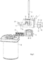
- Figure 1 shows an apparatus 1 for automated preparation of samples for imaging or diffraction experiments under cryogenic conditions.
- the apparatus comprises a movable holder 2 for a grid 3, a process chamber 4 for conditioning the grid and applying a sample to the grid and a jet vitrifyer 5.
- the holder 2 comprises a pair of arms 6, 7, similar to a tweezers, to releasably clamp a grid.
- the process chamber 4 comprises a housing 8 defining a hermetically closable main chamber 9 and provided in the top wall with an opening (hidden from view) to allow the holder 2 and the grid 3 to enter and with a slidable tray 10 containing a supply of grids 3 and also functioning as a hermetic closure for the top opening.
- a slidable applicator 15 for a sample, which applicator will be discussed in more detail below.
- Another side of the housing is provided with a further chamber 16 containing a humidifying solution 17, such as a saturated solution of NaCl in water resulting in 75% relative humidity of the air in the humidifying chamber, and communicating with the main chamber 9 via one or more conduits 18 provided with a valve 19.
- the humidifier chamber is provided with a pump 20 to circulate, in a controlled manner and when the valve 19 is open, humidified gas, typically air, between this chamber and the main chamber 9.
- the bottom wall of the housing 8 is provided with a further opening 25 that is aligned with the opening in the top wall of the chamber 9 and with a slide (hidden from view) having an opening corresponding in size and shape to the bottom opening 25.
- the slide is movable between a first positon wherein the bottom opening 25 and the opening in the slide are aligned, such that the holder 2 and the grid 3 can be lowered from the chamber 9 into the jet vitrifyer 5 beneath, and a second position wherein the slide hermetically closes the bottom opening.
- the main chamber is further provided with a Peltier element 30 ( Figures 2 and 3 ) that is provided with a thermocouple and that is aligned with the applicator 15.
- the grid can be urged against the Peltier element by means of the movable holder or it can be placed in a further and stationary holder 31 extending about the Peltier element.
- a temperature sensor 32 and a humidity sensor 33 are provided in the main chamber 9 to measure temperature and humidity of the gas inside.
- the main chamber 9 contains two electrodes, e.g. in the shape of a disc, a first electrode 35 mounted around the Peltier element and a second electrode 36 mounted inside the chamber 9 in register with and facing the first electrode. Both electrodes 35, 36 have a central opening, the first electrode to fit about the Peltier element 30 and the second electrode to enable the sample applicator 15 or at least the sample to pass.
- the applicator 15 comprises a capillary 40 ( Figure 3 ) or a pin 41 ( Figure 4 ) for applying the sample to the grid 3.
- the applicator 15 is also provided with an on-axis visualization system ( Figure 1 ) comprising a camera 42, a mirror 43, and an objective 44.
- the capillary or pin extends through the mirror and the centre of the objective.
- the jet vitrifyer comprises a pair of opposing nozzles 50, 51 and an inner vessel 52 located beneath the nozzles and an outer vessel 53 surrounding the inner vessel.
- the nozzles are formed by the discharge ends of pipes 54, 55 that extend with their feed ends into the outer vessel.
- the apparatus comprises a further nozzle 56 to remove, after the sample has been vitrified in a coolant, residues of the coolant from the sample with a gas.
- Figure 1 also shows a cassette 57 for storing vitrified samples and a Dewar 58 for storage and transport to e.g. an electron microscope.
- a tray containing a plurality of autogrids is positioned on top of the process chamber 4, a first grid is clamped in the holder 2, lowered through the top opening into the main chamber 9 and clamped in the further holder 31 against the Peltier element 30.
- the top opening is closed, the main chamber 9 is evacuated to achieve a vacuum in a range from 0,1 to 1 mbar, and the valve 19 between the main chamber and the humidifying chamber is opened.
- the temperature and humidity in the main chamber and the temperature of the grid are measured by means of the sensors 32, 33, and the thermocouple in the holder 31 and the dew point of the gas in the main chamber is calculated from these measurements.
- the Peltier element 30 is controlled to set the temperature of the grid to a temperature one or more tenths of a degree above the dew point temperature.
- a high voltage is applied over the electrodes 35, 36 to generate a plasma to discharge and/or clean at least the grid 3 (metal support plus carbon film) in the holder 31.
- the applicator 15 is moved to the operating position and the capillary 40 ( Figure 3 ) or pin 41 ( Figure 4 ) is extended into the main chamber.
- a high DC voltage difference is generated between the capillary 40 on the one hand and the grid 3 on the other to create a spray of the sample from the capillary towards the film, thus depositing a thin layer of the sample onto the grid. Deposition is monitored by means of the camera 42.
- the top opening in the process chamber 4 is cleared and the grid is transferred to the movable holder 2.
- the bottom opening is cleared, the grid is lowered into the jet vitrifyer 5 between the nozzles 50, 51, and liquid ethane is jetted from the nozzles 50, 51 to vitrify the sample in less than 5 ms, e.g. in 2 ms.
- the rest of the grid is cooled as well.
- the grid carrying the sample is lowered into the inner vessel 52 for cooling the holder 2 and for temporary storage in the liquid nitrogen.
- the apparatus can also be used in conjunction with standard EM grids, as shown in Figure 6 .
- the grid instead of transferring the grid from a movable holder to a further stationary holder (31) in the process chamber, the grid can remain in the movable holder (2) and be moved from one station to the next by that holder. In that case, it is preferred that the holder provides a close fit inside at least the top opening in the chamber to maintain conditions inside the chamber.
- the apparatus can comprise a mechanism, such as air blades 60, for removing residual medium, typically liquid, from an incubated sample on a support.
Landscapes
- Chemical & Material Sciences (AREA)
- Analytical Chemistry (AREA)
- Physics & Mathematics (AREA)
- Health & Medical Sciences (AREA)
- Life Sciences & Earth Sciences (AREA)
- Biochemistry (AREA)
- General Health & Medical Sciences (AREA)
- General Physics & Mathematics (AREA)
- Immunology (AREA)
- Pathology (AREA)
- Sampling And Sample Adjustment (AREA)
Description
- The invention relates to method of and apparatus for preparing samples, such as (single) particles, e.g. macromolecular compounds, e.g. proteins, viruses, cells, bacteria, nanoparticles, and crystals, for imaging, e.g. in a cryo-electron microscope (EM), or diffraction experiments, e.g. inspection by ionizing radiation, under cryogenic conditions.
- According to the present invention, there is provided in a first aspect a method of preparing a sample for imaging under cryogenic conditions or diffraction experiments under cryogenic conditions according to
claim 1. -
EP 2 381 236 A1 - S. Kasas et al. "Vitrification of cryoelectron microscopy specimens revealed by high-speed photographic imaging", Journal of Microscopy, Vol. 211, , contains a detailed analysis of the mechanism of sample vitrification through plunge freezing of sample grids.
-
EP 3 018 467 -
EP 2 853 847 -
EP 1 489 642 A1 - It is an object of the present invention to provide an improved method of and apparatus for preparing samples, in particular naturally hydrated samples, for example prokaryotic or eukaryotic cells or a protein solution, for imaging or diffraction experiments under cryogenic conditions.
- To this end, the apparatus according to the present invention is characterized in that the sample is vitrified by directing a jet of liquid coolant to the center of the film and onto the sample, preferably directly onto the sample, i.e. without encapsulating or fixating chemicals.
- Thus, the sample is vitrified first in the center of the support and from there towards the edge of the support, reducing or excluding effects of features, such as reinforcement of the support, located on that edge. More specifically, the present method enables extreme cooling rates in the sample itself, e.g. cooling rates in excess of 50.000 K/s.
- Suitable coolants include liquid ethane, ethane-propane, helium, and nitrogen. Coolants preferably have a temperature in a range from 4 to 150 K, preferably in a range from 4 to 120 K.
- In an embodiment, the time between completion of the application of the sample to the film and jet vitrification is short, e.g. less than a second, preferably less than 100 ms (milliseconds), preferably less than 50 ms, preferably less than 20 ms, preferably less than 10 ms. In an example, upon completion of the application of the sample to the film, the sample is aligned with the jets and the jets are immediately activated when the sample reaches this position.
- To suppress or prevent the formation of artifacts in the vitrified sample, in an embodiment, at least one jet of liquid coolant is simultaneously directed to each side of the support. It is preferred that the jets are synchronized to within 0,5 ms from each other.
- In an embodiment, the velocity of the jets of coolant is in a range from 1 to 50 m/s, preferably in a range from 1 to 20 m/s, and/or the combined mass flow rate of the jets is in a range from 0,1 to 100 L/min.
- In a further embodiment, after the sample has been vitrified, residues of the coolant are removed from the sample, e.g. by blowing the residues off the sample by means of a gas, such as nitrogen. It is preferred that the gas has a temperature in a range from 93 to 120 K, to prevent on the one hand the liquid coolant from freezing and prevent on the other hand the formation of crystalline ice in the sample.
- In another embodiment, the sample, film, support and the gripper holding the support are advanced, after vitrification, into a coolant to cool the gripper and prevent heat from the gripper to undo vitrification.
- In another embodiment, that can be implemented independent from the jet(s), the sample carrier is exposed to a plasma, before applying the sample to the sample carrier.
- The plasma will (glow) discharge sample carrier rendering the component or components of the sample carrier hydrophilic, which in turn facilitates a substantially even application of the sample to the sample carrier. Instead of or in addition to (glow) discharge, the plasma cleans the sample carrier. It is preferred that the sample carrier is subjected to a plasma just prior to applying the sample to the sample carrier, e.g. less than 15 minutes, preferably less than 10 minutes before applying the sample to the sample carrier.
- In another embodiment, that can be implemented independent from the jet(s), the sample is applied to, e.g. printed onto, the sample carrier by means of a capillary or a pin.
- In a preferred example, the capillary has an inner diameter in a range from 0,1 to 200 µm, preferably in a range from 0,1 to 100 µm. In a refinement, a plunger is located within the capillary and arranged to displace, e.g. by linear movement within the capillary, a tiny droplet, having a volume in a range from 1 to 100 pL towards the sample carrier. In another embodiment, a droplet is adhered to the pin.
- When the capillary or pin approaches the hydrophilic sample carrier and the droplet touches the sample carrier, the droplet can be spread to create a thin layer, e.g. by moving the capillary or pin along the sample carrier (or vice versa) in a systematic pattern, such as parallel straight lines, concentric circles, or a spiral, e.g. until the capillary or the droplet is exhausted. Alternatively, several droplets can be applied on different locations on the sample carrier.
- In an embodiment, a reservoir, e.g. a pipette, is provided to supply the pin of capillary with sample. E.g., a droplet or meniscus is temporarily expelled from the reservoir, sample is taken from the drop or meniscus by means of the pin or capillary, once or repeatedly until sufficient sample has been applied to the sample carrier or carriers, and the droplet or meniscus is withdrawn into the reservoir. The reservoir containing the sample can be stored for future use.
- In another embodiment, a high DC voltage difference is applied between the capillary or pin on the one hand and the sample carrier on the other, creating an electrospray of the sample towards the sample carrier.
- In an embodiment, the sample is in a capillary that is made of metal or metal coated polymer or glass or at least comprises an electrode, wherein the metal or electrode is connected to a high DC voltage, preferably having a voltage in a range from 1 to 5 kV. In a refinement, a metal ring is mounted a few millimeters away from the outlet opening of the capillary and connected to a ground or lower DC voltage. The ring accelerates the liquid out of the capillary, forming a spray of very tiny droplets, much smaller than droplets achieved with e.g. 'inkjet' technology. These droplets hit the glow-discharged hydrophilic film and form a thin layer.
- In another embodiment, that can be implemented independent from the elements presented above, such as the jet(s), at least prior to and preferably also during and after application of the sample to the sample carrier, the temperature of the sample carrier is adjusted to a temperature around, at or above the dew point of the gas surrounding the sample carrier, preferably to one or more tenths of a degree, e.g. in a range from 0,1 to 1,0 degrees, below or above the dew point temperature of the gas surrounding the sample carrier. In an example, the dew point temperature is calculated from temperature and humidity measurements of the gas surrounding the sample carrier. The temperature of the sample carrier is measured as well. These three measurements are used in a closed feedback loop to control e.g. a Peltier element that thermally contacts the sample carrier. Thus, exchange of water, in particular evaporation, between the sample and the surrounding gas is suppressed or, ideally, prevented and reproducibility is enhanced.
- In a further embodiment, one or more of the above steps, preferably all steps are carried out in a closed chamber, preferably providing controlled temperature and humidity.
- According to the present invention, there is provided in a second aspect an apparatus of preparing a sample for imaging under cryogenic conditions or diffraction experiments under cryogenic conditions according to claim 11.
- In an embodiment, at least one nozzle is located on each side of the support. In a further embodiment, the holder is movable between at least two positions, a first position at the applicator or a mechanism for removing residual medium from an incubated sample on the sample carrier and a further position in front of the nozzle(s).
- Another embodiment comprises an inner vessel located beneath the nozzles, and preferably beneath the holder for the support, and an outer vessel surrounding the inner vessel and wherein the nozzles are located at the discharge end of pipes that extend with their feed ends into the outer vessel. When the outer vessel is pressurized, e.g. by means of gas pressure above the liquid surface in the outer vessel and in a range from 0,5 to 5 bar, preferably in a range from 1 to 4 bar, the liquid is pressed out through the pipes and nozzles at least substantially simultaneously. Also, the expelled coolant will be collected in the inner vessel. After vitrifying the sample on the support, the support can be lowered to yet a further position, preferably into the inner vessel, for temporary storage. Finally, the support can be transferred and stored in another vessel with liquid nitrogen.
- In an embodiment, the apparatus comprises a further nozzle to remove, after the sample has been vitrified in a coolant, residues of the coolant from the sample with a gas.
- In another embodiment, that can be implemented independent from the jet(s), the apparatus comprises an electrode, e.g. a plate or disc, on either side of the holder and, when it is placed in the holder, the sample carrier.
- As explained above, the electrodes can be used to generate a plasma to discharge and/or clean sample carrier, e.g. the support and film. Also, if sample preparation is carried out in a closed chamber e.g. used to form a vacuum in a range from 0,1 to 1 mbar, the plasma can be employed to decontaminate the chamber, e.g. to sterilize the chamber after sample preparation. This is advantageous especially when processing bioactive samples, such as viruses and bacteria.
- In an embodiment, the electrodes are coupled to a voltage source that generates a voltage between the electrodes in a range from 1 to 5 Volt DC.
- In another embodiment, that can be implemented independent from the elements presented above, such as the jet(s), the applicator comprises a capillary or a pin for applying the sample to the sample carrier.
- The applicator and pin have been discussed above. If the apparatus comprises a combination of the above-mentioned electrodes and a capillary or a pin, one or both of the electrodes can be used to generate a plasma and subsequently to apply a high DC voltage difference between the capillary on the one hand and the support on the other to create a spray of the sample from the capillary towards the sample carrier.
- In an embodiment, the holder, and thus a sample carrier in it, and the capillary or pin are movable relative to each other, preferably in a systematic pattern, to apply a film or spots of the sample to the sample carrier.
- In a further embodiment, that can be implemented independent from the elements presented above, such as the jet(s), the apparatus comprises a cooling and/or heating element, e.g. a Peltier element, for the sample carrier, a temperature sensor and a humidity sensor, and a controller arranged to calculate the dew point of the gas surrounding the sample carrier and to adjust, by means of the element, the temperature of the sample carrier to a temperature around, at or above the dew point of the gas surrounding the sample carrier.
- In a refinement, the apparatus is configured to vitrify samples on a room temperature assembled autogrid. The autogrid is treated and handled during the entire process in an automated way. In a further refinement, one or more, preferably all of the moving parts are actuated and controlled by a microcontroller and a graphical user interface for the user. After loading the autogrids into the machine an automated process takes place.
- Within the framework of the present invention, it is preferred that the sample be applied in a layer having a thickness less than 10 µm and, if the sample is prepared for a cryo-electron microscope, less than 200 nm. Suitable films on a support comprise normal EM grids, grids with cells, and so-named "autogrids" comprising a reinforcing ring. Preferred films include, but are not limited to, silicon nitride films and carbon and gold foils. The term "incubated sample" has its usual meaning, i.e. a sample maintained under conditions suitable for development, e.g. growth of the sample.
-
WO 2013/109405 relates to methods and compositions for preparation of complex specimen arrays for analysis by electron microscopy. These methods and compositions can permit high throughput screening of samples on single EM grid supports using sample volumes in the nanoliter and picoliter range. -
WO 2013/109406 relates to methods and devices for preparing frozen vitrified samples for transmission electron microscopy. By reducing the volume of sample from microliter scale to picoliter scale, the requirement for blotting of excess fluid is minimized or eliminated. -
US 2010/181495 relates to method and a device for preparing specimens for a cryo-electron microscope, wherein a carrier is fixed to a holder, sample liquid is applied to the carrier, and a blotting device for removing excess sample liquid from the carrier by means of the absorbing medium is applied. -
WO 02/077612 -
WO 2017/005297, published on 12 January 2017 , relates to a preparation system for preparing a sample for electron microscopy, comprising a liquid handling system, a support structure that is configured to accommodate the sample, and a temperature-controlled stage that is configured to keep said support structure at a pre-defined temperature when the support structure is arranged on the temperature-controlled stage, e.g. at a dew point temperature of the environment, with the possibility of establishing a small offset temperature to induce evaporation/condensation. - J.C. Gilkey et al., "Advances in Ultrarapid Freezing for the Preservation of Cellular Ultrastructure", Journal of Electron Microscopy Technique, 3:177-210 (1986) addresses, amongst other things, jet freezing of large and sturdy samples.
- R. van Venetië, "Propane jet-freezing: a valid ultra-rapid freezing method for the preservation of temperature dependent lipid phases", Journal of microscopy, vol. 123, pages 287-292 (1981), relates to a temperature controlled specimen stage on a jet-freezing apparatus, wherein the specimen is placed between two silver plates.
- N.L. Burstein et al., "Cryofixation of tissue surfaces by a propane jet for electron microscopy", Micron, vol. 9, pages 191-198 (1969), relates to the rapid freezing of tissues, e.g a cornea, by exposure to a high velocity jet of liquid propane at its freezing point.
-
WO 2013/152239 relates to a sample vitrification system, which includes a capsule structure configured for carrying a biological sample within a compartment while the sample is subjected to ultra-rapid freezing by way of a cryogenic coolant jet. - W.B. Bald, "The relative merits of various cooling methods", Journal of microscopy, vol. 140, pages 17-40 (1985), discusses three different methods of rapidly cooling specimens prior to microscopical analysis.
- The invention will now be explained in more detail with reference to the Figures, which show an embodiment of the present invention.
-
Figure 1 is a perspective view of an apparatus according to the present invention for preparing samples for imaging or diffraction experiments under cryogenic conditions. -
Figure 2 is a perspective view of a process chamber in the apparatus shown inFigure 1 . -
Figure 3 is a perspective view of a first example of an applicator for a sample. -
Figure 4 is a perspective view of a second example of an applicator for a sample. -
Figure 5 is a perspective view of jet vitrifyer. -
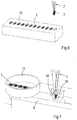
Figure 6 is a perspective view of supply box containing standard grids. -
Figure 7 is a perspective view of a mechanism for removing residual medium from an incubated sample. -
Figure 1 shows anapparatus 1 for automated preparation of samples for imaging or diffraction experiments under cryogenic conditions. The apparatus comprises amovable holder 2 for agrid 3, a process chamber 4 for conditioning the grid and applying a sample to the grid and ajet vitrifyer 5. - The
holder 2 comprises a pair of arms 6, 7, similar to a tweezers, to releasably clamp a grid. - The process chamber 4 comprises a
housing 8 defining a hermetically closablemain chamber 9 and provided in the top wall with an opening (hidden from view) to allow theholder 2 and thegrid 3 to enter and with aslidable tray 10 containing a supply ofgrids 3 and also functioning as a hermetic closure for the top opening. One of the sides of the housing is provided with aslidable applicator 15 for a sample, which applicator will be discussed in more detail below. Another side of the housing is provided with afurther chamber 16 containing ahumidifying solution 17, such as a saturated solution of NaCl in water resulting in 75% relative humidity of the air in the humidifying chamber, and communicating with themain chamber 9 via one ormore conduits 18 provided with avalve 19. The humidifier chamber is provided with apump 20 to circulate, in a controlled manner and when thevalve 19 is open, humidified gas, typically air, between this chamber and themain chamber 9. - In this example, the bottom wall of the
housing 8 is provided with afurther opening 25 that is aligned with the opening in the top wall of thechamber 9 and with a slide (hidden from view) having an opening corresponding in size and shape to thebottom opening 25. The slide is movable between a first positon wherein thebottom opening 25 and the opening in the slide are aligned, such that theholder 2 and thegrid 3 can be lowered from thechamber 9 into thejet vitrifyer 5 beneath, and a second position wherein the slide hermetically closes the bottom opening. - The main chamber is further provided with a Peltier element 30 (
Figures 2 and 3 ) that is provided with a thermocouple and that is aligned with theapplicator 15. The grid can be urged against the Peltier element by means of the movable holder or it can be placed in a further andstationary holder 31 extending about the Peltier element. Atemperature sensor 32 and ahumidity sensor 33 are provided in themain chamber 9 to measure temperature and humidity of the gas inside. - The
main chamber 9 contains two electrodes, e.g. in the shape of a disc, afirst electrode 35 mounted around the Peltier element and asecond electrode 36 mounted inside thechamber 9 in register with and facing the first electrode. Bothelectrodes Peltier element 30 and the second electrode to enable thesample applicator 15 or at least the sample to pass. - The
applicator 15 comprises a capillary 40 (Figure 3 ) or a pin 41 (Figure 4 ) for applying the sample to thegrid 3. Theapplicator 15 is also provided with an on-axis visualization system (Figure 1 ) comprising acamera 42, amirror 43, and an objective 44. The capillary or pin extends through the mirror and the centre of the objective. - The jet vitrifyer comprises a pair of opposing
nozzles inner vessel 52 located beneath the nozzles and anouter vessel 53 surrounding the inner vessel. The nozzles are formed by the discharge ends ofpipes further nozzle 56 to remove, after the sample has been vitrified in a coolant, residues of the coolant from the sample with a gas. -
Figure 1 also shows acassette 57 for storing vitrified samples and aDewar 58 for storage and transport to e.g. an electron microscope. - During operation, a tray containing a plurality of autogrids is positioned on top of the process chamber 4, a first grid is clamped in the
holder 2, lowered through the top opening into themain chamber 9 and clamped in thefurther holder 31 against thePeltier element 30. The top opening is closed, themain chamber 9 is evacuated to achieve a vacuum in a range from 0,1 to 1 mbar, and thevalve 19 between the main chamber and the humidifying chamber is opened. The temperature and humidity in the main chamber and the temperature of the grid are measured by means of thesensors holder 31 and the dew point of the gas in the main chamber is calculated from these measurements. ThePeltier element 30 is controlled to set the temperature of the grid to a temperature one or more tenths of a degree above the dew point temperature. - Subsequently, a high voltage is applied over the
electrodes holder 31. - Next, the
applicator 15 is moved to the operating position and the capillary 40 (Figure 3 ) or pin 41 (Figure 4 ) is extended into the main chamber. - In a first example, shown in
Figure 3 , a high DC voltage difference is generated between the capillary 40 on the one hand and thegrid 3 on the other to create a spray of the sample from the capillary towards the film, thus depositing a thin layer of the sample onto the grid. Deposition is monitored by means of thecamera 42. - In a second example, shown in
Figure 4 , an amount of sample is adhered to the tip of thepin 41 and the pin is advanced towards thegrid 3 until the sample touches the grid. The pin is moved relative to theholder 31 and thegrid 3 in a systematic pattern, to apply a thin layer of the sample to the grid. This 'printing' process is monitored by means of thecamera 42. - Immediately after the sample has been applied to the grid, the top opening in the process chamber 4 is cleared and the grid is transferred to the
movable holder 2. The bottom opening is cleared, the grid is lowered into thejet vitrifyer 5 between thenozzles nozzles inner vessel 52 for cooling theholder 2 and for temporary storage in the liquid nitrogen. - The invention is not restricted to the above-described embodiments, which can be varied in a number of ways within the scope of the claims. For instance, instead of grids comprising a reinforcing ring, the apparatus can also be used in conjunction with standard EM grids, as shown in
Figure 6 . Also, instead of transferring the grid from a movable holder to a further stationary holder (31) in the process chamber, the grid can remain in the movable holder (2) and be moved from one station to the next by that holder. In that case, it is preferred that the holder provides a close fit inside at least the top opening in the chamber to maintain conditions inside the chamber. As a further example or add-on, shown inFigure 7 , the apparatus can comprise a mechanism, such asair blades 60, for removing residual medium, typically liquid, from an incubated sample on a support.
Claims (15)
- Method of preparing a sample for imaging under cryogenic conditions or diffraction experiments under cryogenic conditions, comprising the steps of applying a sample to a sample carrier (3), in particular a grid, the sample carrier (3) comprising a film on a support and
vitrifying the sample, wherein the sample is vitrified by directing a jet (50, 51) of liquid coolant to the center of the sample carrier (3) and onto the sample so that the sample is vitrified first in the center of the support and from there towards the edge of the support. - Method according to claim 1, wherein the time between completion of the application of the sample to the sample carrier (3) and jet vitrification is less than a second.
- Method according to claim 1 or 2, comprising simultaneously directing at least one jet (50, 51) of liquid coolant to each side of the support (3).
- Method according to claim 3, wherein the jets (50, 51) are synchronized to within 0,5 ms from each other.
- Method according to any one of the preceding claims, wherein the velocity of the at least one jet (50, 51) of coolant is in a range from 1 to 50 m/s, preferably in a range from 1 to 20 m/s, and/or wherein the combined mass flow rate of the jets (50, 51) is in 0,1 to 100 L/min.
- Method according to any one of the preceding claims, wherein, after the sample has been vitrified, residues of the coolant are removed from the sample.
- Method according to any one of the preceding claims, wherein the sample, sample carrier and a gripper (2) holding the sample carrier are advanced, after vitrification, into a coolant to cool the gripper (2) and prevent heat from the gripper (2) to undo vitrification.
- Method according to any one of the preceding claims, wherein, before applying the sample to the film (3), the film (3) and the support are exposed to a plasma.
- Method according to any one of the preceding claims, wherein at least prior to application of the sample to the sample carrier (3) the temperature of sample carrier (3) is adjusted to a temperature sample carrier, at or above the dew point of the gas surrounding the sample carrier (3).
- Method according to any one of the preceding claims, wherein one or more of the above steps, preferably all steps are carried out in a closed chamber (9).
- Apparatus (1) for preparing samples for imaging under cryogenic conditions or diffraction experiments under cryogenic conditions, comprising: a sample carrier (3), in particular a grid, the sample carrier (3) comprising a film on a support; a holder (2, 31) for the sample carrier; an applicator (15) for applying a sample to the sample carrier (3) in the holder (2, 31); and a nozzle (50, 51) arranged to direct a jet of liquid coolant to the center of the sample carrier (3) and onto the sample so that the sample is vitrified first in the center of the support and from there towards the edge of the support.
- Apparatus (1) according to claim 11, comprising at least one nozzle (50, 51) on each side of the support (3).
- Apparatus (1) according to claim 11 or 12, wherein the holder (2, 31) is movable between at least two positions, a first position at the applicator (15) or a mechanism (60) for removing residual medium from an incubated sample on the sample carrier (3) and a further position in front of the nozzle(s) (50, 51).
- Apparatus (1) according to any one of claims 11-13, comprising an inner vessel (52) located beneath the nozzles (50, 51) and an outer vessel (53) surrounding the inner vessel (52) and wherein the nozzles (50, 51) are located at the discharge end of pipes (54, 55) that extend with their feed ends into the outer vessel (53).
- Apparatus (1) according to any one of the claims 11-14, comprising a cooling and/or heating element (30) for the sample carrier (3), a temperature sensor (32) and a humidity sensor (33), and a controller arranged to calculate the dew point of the gas surrounding the sample carrier (3) and to adjust, by means of the element (30), the temperature of the sample carrier (3) to a temperature around, at or above the dew point of the gas surrounding the sample carrier (3).
Applications Claiming Priority (2)
| Application Number | Priority Date | Filing Date | Title |
|---|---|---|---|
| EP16175829.7A EP3260839B1 (en) | 2016-06-22 | 2016-06-22 | Method for preparing samples for imaging or diffraction experiments under cryogenic conditions |
| PCT/EP2017/065466 WO2017220750A1 (en) | 2016-06-22 | 2017-06-22 | Method of and apparatus for preparing samples for imaging or diffraction experiments under cryogenic conditions |
Publications (2)
| Publication Number | Publication Date |
|---|---|
| EP3475681A1 EP3475681A1 (en) | 2019-05-01 |
| EP3475681B1 true EP3475681B1 (en) | 2020-06-17 |
Family
ID=56203216
Family Applications (2)
| Application Number | Title | Priority Date | Filing Date |
|---|---|---|---|
| EP16175829.7A Active EP3260839B1 (en) | 2016-06-22 | 2016-06-22 | Method for preparing samples for imaging or diffraction experiments under cryogenic conditions |
| EP17731174.3A Revoked EP3475681B1 (en) | 2016-06-22 | 2017-06-22 | Method of and apparatus for preparing samples for imaging or diffraction experiments under cryogenic conditions |
Family Applications Before (1)
| Application Number | Title | Priority Date | Filing Date |
|---|---|---|---|
| EP16175829.7A Active EP3260839B1 (en) | 2016-06-22 | 2016-06-22 | Method for preparing samples for imaging or diffraction experiments under cryogenic conditions |
Country Status (5)
| Country | Link |
|---|---|
| US (1) | US11796432B2 (en) |
| EP (2) | EP3260839B1 (en) |
| CN (1) | CN109690281B (en) |
| DK (2) | DK3260839T3 (en) |
| WO (1) | WO2017220750A1 (en) |
Cited By (2)
| Publication number | Priority date | Publication date | Assignee | Title |
|---|---|---|---|---|
| EP4067860A1 (en) | 2021-03-31 | 2022-10-05 | FEI Company | Method of preparing a cryogenic sample with improved cooling characteristics |
| EP4095508A1 (en) | 2021-05-26 | 2022-11-30 | Bormans Beheer B.V. | Method and apparatus for preparing samples under cryogenic conditions for imaging or diffraction experiments in an electron microscope |
Families Citing this family (16)
| Publication number | Priority date | Publication date | Assignee | Title |
|---|---|---|---|---|
| GB201613173D0 (en) * | 2016-07-29 | 2016-09-14 | Medical Res Council | Electron microscopy |
| JP7512250B2 (en) * | 2018-04-05 | 2024-07-08 | シュウ・ハン | Improved ultrafast cooling system and method of use |
| CN111337521B (en) * | 2018-11-30 | 2021-03-05 | 浙江大学 | A multi-degree-of-freedom sample holder |
| US11703429B2 (en) | 2019-02-14 | 2023-07-18 | Nanosoft, LLC | Cryogenic transmission electron microscopy sample preparation |
| US11035766B2 (en) | 2019-02-14 | 2021-06-15 | Nanosoft, Llc. | Cryogenic transmission electron microscopy sample preparation |
| EP3739615A1 (en) | 2019-05-14 | 2020-11-18 | Universiteit Maastricht | Sample carrier for electron microscopy |
| CN112444530A (en) * | 2019-09-04 | 2021-03-05 | 浙江大学 | Micro sample preparation device for cryoelectron microscope and sample preparation method thereof |
| US12366509B2 (en) | 2019-10-04 | 2025-07-22 | Mitegen, Llc | Sample supports and sample cooling systems for cryo-electron microscopy |
| CN113484108B (en) * | 2021-05-31 | 2022-03-11 | 中国科学院生物物理研究所 | Method for preparing cryo-electron microscope samples by using interfacial charge |
| GB2614323B (en) * | 2021-12-30 | 2024-03-13 | Fei Co | A method and apparatus of preparing a sample of one or more molecule(s) for imaging with a cryo-electron microscope |
| EP4591043A1 (en) * | 2022-09-20 | 2025-07-30 | cryoWrite AG | Gripper unit and transfer system |
| EP4394348A1 (en) | 2022-12-30 | 2024-07-03 | Universiteit Maastricht | Method of and apparatus for vitrifying aqueous samples |
| CN116698894B (en) * | 2023-08-01 | 2023-10-24 | 中国科学院生物物理研究所 | Inactivated frozen electron microscope sample preparation system and preparation method |
| CN117054183B (en) * | 2023-08-09 | 2024-04-02 | 青岛海洋地质研究所 | A device and method for generating smooth surface hydrate |
| CN117782742B (en) * | 2024-01-04 | 2026-07-17 | 北京大学 | Frozen solution sample preparation device suitable for ultrahigh vacuum system |
| WO2025199620A1 (en) * | 2024-03-27 | 2025-10-02 | Neoglacia Inc. | Cryo-electron microscopy sample preparation system, and modules and methods for operating same |
Citations (5)
| Publication number | Priority date | Publication date | Assignee | Title |
|---|---|---|---|---|
| US4336691A (en) | 1979-12-13 | 1982-06-29 | The Board Of Trustees Of The Leland Stanford Junior University | Cryojet rapid freezing apparatus |
| EP2381266A1 (en) | 2010-04-23 | 2011-10-26 | Renesas Electronics Corporation | Self-diagnosis system and test circuit determination method |
| US20120255313A1 (en) | 2011-04-06 | 2012-10-11 | Igor Katkov | Method And Scalable Devices For Hyper-Fast Cooling |
| EP2853847B1 (en) | 2013-09-30 | 2016-02-03 | Fei Company | Preparation of cryogenic sample for charged-particle microscopy |
| EP3179229A1 (en) | 2015-12-11 | 2017-06-14 | FEI Company | Preparation of cryogenic sample for charged-particle microscopy |
Family Cites Families (17)
| Publication number | Priority date | Publication date | Assignee | Title |
|---|---|---|---|---|
| US2680371A (en) | 1951-07-13 | 1954-06-08 | Illinois Testing Laboratories | Dew point measuring device |
| US4753887A (en) * | 1986-08-07 | 1988-06-28 | Regents Of The University Of Minnesota | Controlled environment vitrification system for preparation of liquids |
| US6893877B2 (en) * | 1998-01-12 | 2005-05-17 | Massachusetts Institute Of Technology | Methods for screening substances in a microwell array |
| NL1017669C2 (en) * | 2001-03-22 | 2002-09-24 | Univ Maastricht | Device for the manufacture of preparations for a cryo-electron microscope. |
| NL1023717C2 (en) | 2003-06-20 | 2004-12-21 | Fei Co | Preparation carrier for carrying a preparation to be irradiated with an electron beam. |
| US20080268164A1 (en) * | 2007-04-26 | 2008-10-30 | Air Products And Chemicals, Inc. | Apparatuses and Methods for Cryogenic Cooling in Thermal Surface Treatment Processes |
| EP2224800B1 (en) * | 2007-11-20 | 2013-01-09 | Max-Planck-Gesellschaft zur Förderung der Wissenschaften e.V. | Ultra-rapid freezing device and method |
| AT507079B1 (en) * | 2009-01-22 | 2010-02-15 | Leica Mikrosysteme Gmbh | DEVICE AND METHOD FOR PREPARING SAMPLES |
| US9312095B2 (en) * | 2010-03-24 | 2016-04-12 | Brown University | Method and system for automating sample preparation for microfluidic cryo TEM |
| US8445874B2 (en) * | 2010-04-11 | 2013-05-21 | Gatan Inc. | Ion beam sample preparation apparatus and methods |
| EP2381236A1 (en) | 2010-04-23 | 2011-10-26 | Fei Company | Apparatus for preparing a cryogenic TEM specimen |
| US9702795B2 (en) | 2012-01-17 | 2017-07-11 | The Scripps Research Institute | Apparatus and method for producing specimens for electron microscopy |
| EP2805144A4 (en) | 2012-01-17 | 2015-09-09 | Scripps Research Inst | PREPARATION OF ORDERED SAMPLE SETS ON A GRID FOR ELECTRONIC MICROSCOPY |
| WO2013152239A1 (en) * | 2012-04-04 | 2013-10-10 | National University Of Singapore | Cryo-preparation systems and methods for near-instantaneous vitrification of biological samples |
| GB2537579A (en) * | 2014-11-07 | 2016-10-26 | Linkam Scient Instr Ltd | Microscopic sample preparation |
| EP3062082B1 (en) * | 2015-02-25 | 2018-04-18 | Fei Company | Preparation of sample for charged-particle microscopy |
| JP6861207B2 (en) * | 2015-07-06 | 2021-04-21 | ウニヴェアズィテート バーゼル | Lossless low temperature grid preparation stage for high resolution electron microscope |
-
2016
- 2016-06-22 EP EP16175829.7A patent/EP3260839B1/en active Active
- 2016-06-22 DK DK16175829.7T patent/DK3260839T3/en active
-
2017
- 2017-06-22 DK DK17731174.3T patent/DK3475681T3/en active
- 2017-06-22 EP EP17731174.3A patent/EP3475681B1/en not_active Revoked
- 2017-06-22 WO PCT/EP2017/065466 patent/WO2017220750A1/en not_active Ceased
- 2017-06-22 US US16/312,806 patent/US11796432B2/en active Active
- 2017-06-22 CN CN201780051499.0A patent/CN109690281B/en active Active
Patent Citations (5)
| Publication number | Priority date | Publication date | Assignee | Title |
|---|---|---|---|---|
| US4336691A (en) | 1979-12-13 | 1982-06-29 | The Board Of Trustees Of The Leland Stanford Junior University | Cryojet rapid freezing apparatus |
| EP2381266A1 (en) | 2010-04-23 | 2011-10-26 | Renesas Electronics Corporation | Self-diagnosis system and test circuit determination method |
| US20120255313A1 (en) | 2011-04-06 | 2012-10-11 | Igor Katkov | Method And Scalable Devices For Hyper-Fast Cooling |
| EP2853847B1 (en) | 2013-09-30 | 2016-02-03 | Fei Company | Preparation of cryogenic sample for charged-particle microscopy |
| EP3179229A1 (en) | 2015-12-11 | 2017-06-14 | FEI Company | Preparation of cryogenic sample for charged-particle microscopy |
Non-Patent Citations (3)
| Title |
|---|
| "Handbook of Cryo-Preparation Methods for Electron Microscopy", 1 January 2009, CRC PRESS, article FREDERIK PETER M., DE HAAS F., STORMS M.H.S., CAVALIER A., SPEHNER D., HUMBEL B. M.: "Chapter 4: Control verifiction", pages: 70 - 99, XP055967125 |
| MULLER ET AL.: "Freezing in a Propane Jet and its Application in Freeze-Fracturing", MIKROSKOPIE, vol. 36, 1980, pages 129 - 140, XP055487620 |
| VAN VENETIE ET AL.: "Propane jet-freezing: a valid ultra- rapid freezing method for the preservation of temperature dependent lipid phases", J. OF MICROSCOPY, vol. 123, no. Pt 3, 1981, pages 287 - 292, XP055323136, DOI: 10.1111/j.1365-2818.1981.tb02472.x |
Cited By (3)
| Publication number | Priority date | Publication date | Assignee | Title |
|---|---|---|---|---|
| EP4067860A1 (en) | 2021-03-31 | 2022-10-05 | FEI Company | Method of preparing a cryogenic sample with improved cooling characteristics |
| EP4095508A1 (en) | 2021-05-26 | 2022-11-30 | Bormans Beheer B.V. | Method and apparatus for preparing samples under cryogenic conditions for imaging or diffraction experiments in an electron microscope |
| NL2028288B1 (en) | 2021-05-26 | 2022-12-12 | Bormans Beheer B V | Method and apparatus for preparing samples under cryogenic conditions for imaging or diffraction experiments in an electron microscope |
Also Published As
| Publication number | Publication date |
|---|---|
| EP3475681A1 (en) | 2019-05-01 |
| DK3475681T3 (en) | 2020-08-10 |
| US20190170625A1 (en) | 2019-06-06 |
| DK3260839T3 (en) | 2021-04-19 |
| US11796432B2 (en) | 2023-10-24 |
| CN109690281A (en) | 2019-04-26 |
| EP3260839B1 (en) | 2021-01-27 |
| EP3260839A1 (en) | 2017-12-27 |
| CN109690281B (en) | 2023-04-28 |
| WO2017220750A1 (en) | 2017-12-28 |
Similar Documents
| Publication | Publication Date | Title |
|---|---|---|
| US11796432B2 (en) | Method of and apparatus for preparing samples for imaging or diffraction experiments under cryogenic conditions | |
| US10241011B2 (en) | Apparatus and method for producing specimens for electron microscopy | |
| EP2853847B1 (en) | Preparation of cryogenic sample for charged-particle microscopy | |
| EP3062082B1 (en) | Preparation of sample for charged-particle microscopy | |
| JP5899377B2 (en) | Charged particle beam apparatus and sample preparation method using the apparatus | |
| CN110062880B (en) | Preparation of non-destructive freezing grid by controlled sample evaporation | |
| EP2626886B1 (en) | Forming a vitrified sample for an electron microscopy | |
| US20220381656A1 (en) | Method and Apparatus for Preparing Samples Under Cryogenic Conditions for Imaging or Diffraction Experiments in an Electron Microscope | |
| US20080293832A1 (en) | Solid sample, solid sample fabricating method, and solid sample fabricating apparatus | |
| JP6997757B2 (en) | Electron microscopy | |
| EP1370846B1 (en) | Device for preparing specimens for a cryo-electron microscope | |
| US20240412942A1 (en) | Apparatus for preparing electron microscopy samples and methods of use thereof | |
| US20180238843A1 (en) | System and method for spray deposition of a chemical onto a substrate | |
| JPH1186772A (en) | FIB assist gas introduction device | |
| CN104048861A (en) | Equipment for processing tissue samples | |
| Resch et al. | Immersion freezing of suspended particles and cells for cryo-electron microscopy | |
| EP4711738A1 (en) | Sample preparation method and device for preparing a vitrified sample layer on a sample holder grid for subsequent cryo electron microscopy | |
| Ott et al. | Preparation of Bunyavirus-Infected Cells for Electron Cryo-Tomography | |
| JPWO2001038602A1 (en) | Compound vapor spraying device and focused ion beam device using the same | |
| WO2025199620A1 (en) | Cryo-electron microscopy sample preparation system, and modules and methods for operating same | |
| WO2024141605A1 (en) | Method of and apparatus for vitrifying aqueous samples |
Legal Events
| Date | Code | Title | Description |
|---|---|---|---|
| STAA | Information on the status of an ep patent application or granted ep patent |
Free format text: STATUS: UNKNOWN |
|
| STAA | Information on the status of an ep patent application or granted ep patent |
Free format text: STATUS: THE INTERNATIONAL PUBLICATION HAS BEEN MADE |
|
| PUAI | Public reference made under article 153(3) epc to a published international application that has entered the european phase |
Free format text: ORIGINAL CODE: 0009012 |
|
| STAA | Information on the status of an ep patent application or granted ep patent |
Free format text: STATUS: REQUEST FOR EXAMINATION WAS MADE |
|
| 17P | Request for examination filed |
Effective date: 20190122 |
|
| AK | Designated contracting states |
Kind code of ref document: A1 Designated state(s): AL AT BE BG CH CY CZ DE DK EE ES FI FR GB GR HR HU IE IS IT LI LT LU LV MC MK MT NL NO PL PT RO RS SE SI SK SM TR |
|
| AX | Request for extension of the european patent |
Extension state: BA ME |
|
| DAV | Request for validation of the european patent (deleted) | ||
| DAX | Request for extension of the european patent (deleted) | ||
| STAA | Information on the status of an ep patent application or granted ep patent |
Free format text: STATUS: REQUEST FOR EXAMINATION WAS MADE |
|
| 17Q | First examination report despatched |
Effective date: 20191126 |
|
| GRAP | Despatch of communication of intention to grant a patent |
Free format text: ORIGINAL CODE: EPIDOSNIGR1 |
|
| STAA | Information on the status of an ep patent application or granted ep patent |
Free format text: STATUS: GRANT OF PATENT IS INTENDED |
|
| INTG | Intention to grant announced |
Effective date: 20200108 |
|
| GRAS | Grant fee paid |
Free format text: ORIGINAL CODE: EPIDOSNIGR3 |
|
| GRAA | (expected) grant |
Free format text: ORIGINAL CODE: 0009210 |
|
| STAA | Information on the status of an ep patent application or granted ep patent |
Free format text: STATUS: THE PATENT HAS BEEN GRANTED |
|
| AK | Designated contracting states |
Kind code of ref document: B1 Designated state(s): AL AT BE BG CH CY CZ DE DK EE ES FI FR GB GR HR HU IE IS IT LI LT LU LV MC MK MT NL NO PL PT RO RS SE SI SK SM TR |
|
| REG | Reference to a national code |
Ref country code: GB Ref legal event code: FG4D |
|
| REG | Reference to a national code |
Ref country code: CH Ref legal event code: EP |
|
| REG | Reference to a national code |
Ref country code: IE Ref legal event code: FG4D |
|
| REG | Reference to a national code |
Ref country code: DE Ref legal event code: R096 Ref document number: 602017018353 Country of ref document: DE |
|
| REG | Reference to a national code |
Ref country code: AT Ref legal event code: REF Ref document number: 1281906 Country of ref document: AT Kind code of ref document: T Effective date: 20200715 |
|
| REG | Reference to a national code |
Ref country code: DK Ref legal event code: T3 Effective date: 20200806 |
|
| REG | Reference to a national code |
Ref country code: SE Ref legal event code: TRGR |
|
| REG | Reference to a national code |
Ref country code: NL Ref legal event code: FP |
|
| PG25 | Lapsed in a contracting state [announced via postgrant information from national office to epo] |
Ref country code: NO Free format text: LAPSE BECAUSE OF FAILURE TO SUBMIT A TRANSLATION OF THE DESCRIPTION OR TO PAY THE FEE WITHIN THE PRESCRIBED TIME-LIMIT Effective date: 20200917 Ref country code: FI Free format text: LAPSE BECAUSE OF FAILURE TO SUBMIT A TRANSLATION OF THE DESCRIPTION OR TO PAY THE FEE WITHIN THE PRESCRIBED TIME-LIMIT Effective date: 20200617 Ref country code: LT Free format text: LAPSE BECAUSE OF FAILURE TO SUBMIT A TRANSLATION OF THE DESCRIPTION OR TO PAY THE FEE WITHIN THE PRESCRIBED TIME-LIMIT Effective date: 20200617 Ref country code: GR Free format text: LAPSE BECAUSE OF FAILURE TO SUBMIT A TRANSLATION OF THE DESCRIPTION OR TO PAY THE FEE WITHIN THE PRESCRIBED TIME-LIMIT Effective date: 20200918 |
|
| REG | Reference to a national code |
Ref country code: LT Ref legal event code: MG4D |
|
| PG25 | Lapsed in a contracting state [announced via postgrant information from national office to epo] |
Ref country code: BG Free format text: LAPSE BECAUSE OF FAILURE TO SUBMIT A TRANSLATION OF THE DESCRIPTION OR TO PAY THE FEE WITHIN THE PRESCRIBED TIME-LIMIT Effective date: 20200917 Ref country code: RS Free format text: LAPSE BECAUSE OF FAILURE TO SUBMIT A TRANSLATION OF THE DESCRIPTION OR TO PAY THE FEE WITHIN THE PRESCRIBED TIME-LIMIT Effective date: 20200617 Ref country code: LV Free format text: LAPSE BECAUSE OF FAILURE TO SUBMIT A TRANSLATION OF THE DESCRIPTION OR TO PAY THE FEE WITHIN THE PRESCRIBED TIME-LIMIT Effective date: 20200617 Ref country code: HR Free format text: LAPSE BECAUSE OF FAILURE TO SUBMIT A TRANSLATION OF THE DESCRIPTION OR TO PAY THE FEE WITHIN THE PRESCRIBED TIME-LIMIT Effective date: 20200617 |
|
| PG25 | Lapsed in a contracting state [announced via postgrant information from national office to epo] |
Ref country code: AL Free format text: LAPSE BECAUSE OF FAILURE TO SUBMIT A TRANSLATION OF THE DESCRIPTION OR TO PAY THE FEE WITHIN THE PRESCRIBED TIME-LIMIT Effective date: 20200617 |
|
| PG25 | Lapsed in a contracting state [announced via postgrant information from national office to epo] |
Ref country code: ES Free format text: LAPSE BECAUSE OF FAILURE TO SUBMIT A TRANSLATION OF THE DESCRIPTION OR TO PAY THE FEE WITHIN THE PRESCRIBED TIME-LIMIT Effective date: 20200617 Ref country code: SM Free format text: LAPSE BECAUSE OF FAILURE TO SUBMIT A TRANSLATION OF THE DESCRIPTION OR TO PAY THE FEE WITHIN THE PRESCRIBED TIME-LIMIT Effective date: 20200617 Ref country code: EE Free format text: LAPSE BECAUSE OF FAILURE TO SUBMIT A TRANSLATION OF THE DESCRIPTION OR TO PAY THE FEE WITHIN THE PRESCRIBED TIME-LIMIT Effective date: 20200617 Ref country code: RO Free format text: LAPSE BECAUSE OF FAILURE TO SUBMIT A TRANSLATION OF THE DESCRIPTION OR TO PAY THE FEE WITHIN THE PRESCRIBED TIME-LIMIT Effective date: 20200617 Ref country code: IT Free format text: LAPSE BECAUSE OF FAILURE TO SUBMIT A TRANSLATION OF THE DESCRIPTION OR TO PAY THE FEE WITHIN THE PRESCRIBED TIME-LIMIT Effective date: 20200617 Ref country code: PT Free format text: LAPSE BECAUSE OF FAILURE TO SUBMIT A TRANSLATION OF THE DESCRIPTION OR TO PAY THE FEE WITHIN THE PRESCRIBED TIME-LIMIT Effective date: 20201019 |
|
| PG25 | Lapsed in a contracting state [announced via postgrant information from national office to epo] |
Ref country code: PL Free format text: LAPSE BECAUSE OF FAILURE TO SUBMIT A TRANSLATION OF THE DESCRIPTION OR TO PAY THE FEE WITHIN THE PRESCRIBED TIME-LIMIT Effective date: 20200617 Ref country code: SK Free format text: LAPSE BECAUSE OF FAILURE TO SUBMIT A TRANSLATION OF THE DESCRIPTION OR TO PAY THE FEE WITHIN THE PRESCRIBED TIME-LIMIT Effective date: 20200617 Ref country code: IS Free format text: LAPSE BECAUSE OF FAILURE TO SUBMIT A TRANSLATION OF THE DESCRIPTION OR TO PAY THE FEE WITHIN THE PRESCRIBED TIME-LIMIT Effective date: 20201017 |
|
| REG | Reference to a national code |
Ref country code: DE Ref legal event code: R026 Ref document number: 602017018353 Country of ref document: DE |
|
| PLBI | Opposition filed |
Free format text: ORIGINAL CODE: 0009260 |
|
| PG25 | Lapsed in a contracting state [announced via postgrant information from national office to epo] |
Ref country code: LU Free format text: LAPSE BECAUSE OF NON-PAYMENT OF DUE FEES Effective date: 20200622 Ref country code: MC Free format text: LAPSE BECAUSE OF FAILURE TO SUBMIT A TRANSLATION OF THE DESCRIPTION OR TO PAY THE FEE WITHIN THE PRESCRIBED TIME-LIMIT Effective date: 20200617 |
|
| PLAX | Notice of opposition and request to file observation + time limit sent |
Free format text: ORIGINAL CODE: EPIDOSNOBS2 |
|
| REG | Reference to a national code |
Ref country code: BE Ref legal event code: MM Effective date: 20200630 |
|
| 26 | Opposition filed |
Opponent name: MURGITROYD & COMPANY Effective date: 20210317 |
|
| PG25 | Lapsed in a contracting state [announced via postgrant information from national office to epo] |
Ref country code: BE Free format text: LAPSE BECAUSE OF NON-PAYMENT OF DUE FEES Effective date: 20200630 Ref country code: SI Free format text: LAPSE BECAUSE OF FAILURE TO SUBMIT A TRANSLATION OF THE DESCRIPTION OR TO PAY THE FEE WITHIN THE PRESCRIBED TIME-LIMIT Effective date: 20200617 |
|
| PLBB | Reply of patent proprietor to notice(s) of opposition received |
Free format text: ORIGINAL CODE: EPIDOSNOBS3 |
|
| REG | Reference to a national code |
Ref country code: AT Ref legal event code: UEP Ref document number: 1281906 Country of ref document: AT Kind code of ref document: T Effective date: 20200617 |
|
| PG25 | Lapsed in a contracting state [announced via postgrant information from national office to epo] |
Ref country code: TR Free format text: LAPSE BECAUSE OF FAILURE TO SUBMIT A TRANSLATION OF THE DESCRIPTION OR TO PAY THE FEE WITHIN THE PRESCRIBED TIME-LIMIT Effective date: 20200617 Ref country code: MT Free format text: LAPSE BECAUSE OF FAILURE TO SUBMIT A TRANSLATION OF THE DESCRIPTION OR TO PAY THE FEE WITHIN THE PRESCRIBED TIME-LIMIT Effective date: 20200617 Ref country code: CY Free format text: LAPSE BECAUSE OF FAILURE TO SUBMIT A TRANSLATION OF THE DESCRIPTION OR TO PAY THE FEE WITHIN THE PRESCRIBED TIME-LIMIT Effective date: 20200617 |
|
| PG25 | Lapsed in a contracting state [announced via postgrant information from national office to epo] |
Ref country code: MK Free format text: LAPSE BECAUSE OF FAILURE TO SUBMIT A TRANSLATION OF THE DESCRIPTION OR TO PAY THE FEE WITHIN THE PRESCRIBED TIME-LIMIT Effective date: 20200617 |
|
| PLCK | Communication despatched that opposition was rejected |
Free format text: ORIGINAL CODE: EPIDOSNREJ1 |
|
| APAH | Appeal reference modified |
Free format text: ORIGINAL CODE: EPIDOSCREFNO |
|
| APBM | Appeal reference recorded |
Free format text: ORIGINAL CODE: EPIDOSNREFNO |
|
| APBP | Date of receipt of notice of appeal recorded |
Free format text: ORIGINAL CODE: EPIDOSNNOA2O |
|
| APBQ | Date of receipt of statement of grounds of appeal recorded |
Free format text: ORIGINAL CODE: EPIDOSNNOA3O |
|
| P01 | Opt-out of the competence of the unified patent court (upc) registered |
Effective date: 20230530 |
|
| APAH | Appeal reference modified |
Free format text: ORIGINAL CODE: EPIDOSCREFNO |
|
| PLAB | Opposition data, opponent's data or that of the opponent's representative modified |
Free format text: ORIGINAL CODE: 0009299OPPO |
|
| PGFP | Annual fee paid to national office [announced via postgrant information from national office to epo] |
Ref country code: DE Payment date: 20250627 Year of fee payment: 9 |
|
| PGFP | Annual fee paid to national office [announced via postgrant information from national office to epo] |
Ref country code: GB Payment date: 20250627 Year of fee payment: 9 Ref country code: DK Payment date: 20250625 Year of fee payment: 9 |
|
| PGFP | Annual fee paid to national office [announced via postgrant information from national office to epo] |
Ref country code: NL Payment date: 20250626 Year of fee payment: 9 |
|
| PGFP | Annual fee paid to national office [announced via postgrant information from national office to epo] |
Ref country code: FR Payment date: 20250625 Year of fee payment: 9 |
|
| PGFP | Annual fee paid to national office [announced via postgrant information from national office to epo] |
Ref country code: AT Payment date: 20250603 Year of fee payment: 9 |
|
| PGFP | Annual fee paid to national office [announced via postgrant information from national office to epo] |
Ref country code: CZ Payment date: 20250605 Year of fee payment: 9 |
|
| PGFP | Annual fee paid to national office [announced via postgrant information from national office to epo] |
Ref country code: IE Payment date: 20250627 Year of fee payment: 9 |
|
| PGFP | Annual fee paid to national office [announced via postgrant information from national office to epo] |
Ref country code: SE Payment date: 20250627 Year of fee payment: 9 |
|
| R26 | Opposition filed (corrected) |
Opponent name: MURGITROYD & COMPANY Effective date: 20210317 |
|
| PGFP | Annual fee paid to national office [announced via postgrant information from national office to epo] |
Ref country code: CH Payment date: 20250701 Year of fee payment: 9 |
|
| REG | Reference to a national code |
Ref country code: DE Ref legal event code: R064 Ref document number: 602017018353 Country of ref document: DE Ref country code: DE Ref legal event code: R103 Ref document number: 602017018353 Country of ref document: DE |
|
| APBU | Appeal procedure closed |
Free format text: ORIGINAL CODE: EPIDOSNNOA9O |
|
| RDAF | Communication despatched that patent is revoked |
Free format text: ORIGINAL CODE: EPIDOSNREV1 |
|
| RDAG | Patent revoked |
Free format text: ORIGINAL CODE: 0009271 |
|
| STAA | Information on the status of an ep patent application or granted ep patent |
Free format text: STATUS: PATENT REVOKED |
|
| REG | Reference to a national code |
Ref country code: CH Ref legal event code: N12 Free format text: ST27 STATUS EVENT CODE: U-0-0-N10-N12 (AS PROVIDED BY THE NATIONAL OFFICE) Effective date: 20260423 |
|
| 27W | Patent revoked |
Effective date: 20260212 |
|
| GBPR | Gb: patent revoked under art. 102 of the ep convention designating the uk as contracting state |
Effective date: 20260212 |
|
| REG | Reference to a national code |
Ref country code: AT Ref legal event code: MA03 Ref document number: 1281906 Country of ref document: AT Kind code of ref document: T Effective date: 20260212 |