EP3475107B1 - Windshield installation system and triangulation method - Google Patents
Windshield installation system and triangulation method Download PDFInfo
- Publication number
- EP3475107B1 EP3475107B1 EP17816382.0A EP17816382A EP3475107B1 EP 3475107 B1 EP3475107 B1 EP 3475107B1 EP 17816382 A EP17816382 A EP 17816382A EP 3475107 B1 EP3475107 B1 EP 3475107B1
- Authority
- EP
- European Patent Office
- Prior art keywords
- windshield
- rail
- vehicle
- triangulation
- further characterized
- Prior art date
- Legal status (The legal status is an assumption and is not a legal conclusion. Google has not performed a legal analysis and makes no representation as to the accuracy of the status listed.)
- Active
Links
Images






Classifications
-
- B—PERFORMING OPERATIONS; TRANSPORTING
- B60—VEHICLES IN GENERAL
- B60J—WINDOWS, WINDSCREENS, NON-FIXED ROOFS, DOORS, OR SIMILAR DEVICES FOR VEHICLES; REMOVABLE EXTERNAL PROTECTIVE COVERINGS SPECIALLY ADAPTED FOR VEHICLES
- B60J1/00—Windows; Windscreens; Accessories therefor
- B60J1/004—Mounting of windows
-
- B—PERFORMING OPERATIONS; TRANSPORTING
- B60—VEHICLES IN GENERAL
- B60J—WINDOWS, WINDSCREENS, NON-FIXED ROOFS, DOORS, OR SIMILAR DEVICES FOR VEHICLES; REMOVABLE EXTERNAL PROTECTIVE COVERINGS SPECIALLY ADAPTED FOR VEHICLES
- B60J1/00—Windows; Windscreens; Accessories therefor
- B60J1/004—Mounting of windows
- B60J1/005—Mounting of windows using positioning means during mounting
-
- B—PERFORMING OPERATIONS; TRANSPORTING
- B23—MACHINE TOOLS; METAL-WORKING NOT OTHERWISE PROVIDED FOR
- B23P—METAL-WORKING NOT OTHERWISE PROVIDED FOR; COMBINED OPERATIONS; UNIVERSAL MACHINE TOOLS
- B23P19/00—Machines for simply fitting together or separating metal parts or objects, or metal and non-metal parts, whether or not involving some deformation; Tools or devices therefor so far as not provided for in other classes
- B23P19/10—Aligning parts to be fitted together
-
- B—PERFORMING OPERATIONS; TRANSPORTING
- B23—MACHINE TOOLS; METAL-WORKING NOT OTHERWISE PROVIDED FOR
- B23P—METAL-WORKING NOT OTHERWISE PROVIDED FOR; COMBINED OPERATIONS; UNIVERSAL MACHINE TOOLS
- B23P6/00—Restoring or reconditioning objects
-
- B—PERFORMING OPERATIONS; TRANSPORTING
- B60—VEHICLES IN GENERAL
- B60J—WINDOWS, WINDSCREENS, NON-FIXED ROOFS, DOORS, OR SIMILAR DEVICES FOR VEHICLES; REMOVABLE EXTERNAL PROTECTIVE COVERINGS SPECIALLY ADAPTED FOR VEHICLES
- B60J1/00—Windows; Windscreens; Accessories therefor
- B60J1/02—Windows; Windscreens; Accessories therefor arranged at the vehicle front, e.g. structure of the glazing, mounting of the glazing
-
- B—PERFORMING OPERATIONS; TRANSPORTING
- B23—MACHINE TOOLS; METAL-WORKING NOT OTHERWISE PROVIDED FOR
- B23P—METAL-WORKING NOT OTHERWISE PROVIDED FOR; COMBINED OPERATIONS; UNIVERSAL MACHINE TOOLS
- B23P19/00—Machines for simply fitting together or separating metal parts or objects, or metal and non-metal parts, whether or not involving some deformation; Tools or devices therefor so far as not provided for in other classes
- B23P19/10—Aligning parts to be fitted together
- B23P19/107—Aligning parts to be fitted together using oscillating, rotating or vibrating movements
-
- B—PERFORMING OPERATIONS; TRANSPORTING
- B23—MACHINE TOOLS; METAL-WORKING NOT OTHERWISE PROVIDED FOR
- B23P—METAL-WORKING NOT OTHERWISE PROVIDED FOR; COMBINED OPERATIONS; UNIVERSAL MACHINE TOOLS
- B23P2700/00—Indexing scheme relating to the articles being treated, e.g. manufactured, repaired, assembled, connected or other operations covered in the subgroups
- B23P2700/50—Other automobile vehicle parts, i.e. manufactured in assembly lines
-
- B—PERFORMING OPERATIONS; TRANSPORTING
- B25—HAND TOOLS; PORTABLE POWER-DRIVEN TOOLS; MANIPULATORS
- B25B—TOOLS OR BENCH DEVICES NOT OTHERWISE PROVIDED FOR, FOR FASTENING, CONNECTING, DISENGAGING, OR HOLDING
- B25B11/00—Work holders not covered by any preceding group in the subclass, e.g. magnetic work holders, vacuum work holders
- B25B11/005—Vacuum work holders
-
- B—PERFORMING OPERATIONS; TRANSPORTING
- B60—VEHICLES IN GENERAL
- B60J—WINDOWS, WINDSCREENS, NON-FIXED ROOFS, DOORS, OR SIMILAR DEVICES FOR VEHICLES; REMOVABLE EXTERNAL PROTECTIVE COVERINGS SPECIALLY ADAPTED FOR VEHICLES
- B60J1/00—Windows; Windscreens; Accessories therefor
- B60J1/004—Mounting of windows
- B60J1/006—Mounting of windows characterised by fixation means such as clips, adhesive, etc.
-
- B—PERFORMING OPERATIONS; TRANSPORTING
- B60—VEHICLES IN GENERAL
- B60J—WINDOWS, WINDSCREENS, NON-FIXED ROOFS, DOORS, OR SIMILAR DEVICES FOR VEHICLES; REMOVABLE EXTERNAL PROTECTIVE COVERINGS SPECIALLY ADAPTED FOR VEHICLES
- B60J1/00—Windows; Windscreens; Accessories therefor
- B60J1/004—Mounting of windows
- B60J1/007—Mounting of windows received in frames to be attached to vehicle
-
- B—PERFORMING OPERATIONS; TRANSPORTING
- B65—CONVEYING; PACKING; STORING; HANDLING THIN OR FILAMENTARY MATERIAL
- B65G—TRANSPORT OR STORAGE DEVICES, e.g. CONVEYORS FOR LOADING OR TIPPING, SHOP CONVEYOR SYSTEMS OR PNEUMATIC TUBE CONVEYORS
- B65G49/00—Conveying systems characterised by their application for specified purposes not otherwise provided for
- B65G49/05—Conveying systems characterised by their application for specified purposes not otherwise provided for for fragile or damageable materials or articles
- B65G49/06—Conveying systems characterised by their application for specified purposes not otherwise provided for for fragile or damageable materials or articles for fragile sheets, e.g. glass
- B65G49/061—Lifting, gripping, or carrying means, for one or more sheets forming independent means of transport, e.g. suction cups, transport frames
-
- Y—GENERAL TAGGING OF NEW TECHNOLOGICAL DEVELOPMENTS; GENERAL TAGGING OF CROSS-SECTIONAL TECHNOLOGIES SPANNING OVER SEVERAL SECTIONS OF THE IPC; TECHNICAL SUBJECTS COVERED BY FORMER USPC CROSS-REFERENCE ART COLLECTIONS [XRACs] AND DIGESTS
- Y10—TECHNICAL SUBJECTS COVERED BY FORMER USPC
- Y10T—TECHNICAL SUBJECTS COVERED BY FORMER US CLASSIFICATION
- Y10T29/00—Metal working
- Y10T29/49—Method of mechanical manufacture
- Y10T29/49718—Repairing
- Y10T29/49721—Repairing with disassembling
- Y10T29/4973—Replacing of defective part
-
- Y—GENERAL TAGGING OF NEW TECHNOLOGICAL DEVELOPMENTS; GENERAL TAGGING OF CROSS-SECTIONAL TECHNOLOGIES SPANNING OVER SEVERAL SECTIONS OF THE IPC; TECHNICAL SUBJECTS COVERED BY FORMER USPC CROSS-REFERENCE ART COLLECTIONS [XRACs] AND DIGESTS
- Y10—TECHNICAL SUBJECTS COVERED BY FORMER USPC
- Y10T—TECHNICAL SUBJECTS COVERED BY FORMER US CLASSIFICATION
- Y10T29/00—Metal working
- Y10T29/49—Method of mechanical manufacture
- Y10T29/49826—Assembling or joining
- Y10T29/49895—Associating parts by use of aligning means [e.g., use of a drift pin or a "fixture"]
- Y10T29/49902—Associating parts by use of aligning means [e.g., use of a drift pin or a "fixture"] by manipulating aligning means
Definitions
- This invention relates to systems and methods used for one-person replacement of a vehicle windshield, specifically to an elongated windshield triangulation assembly having components capable of multi-directional movement that permit its use with all vehicle windshields regardless of size and curvature, and which is used sequentially to first create a reproducible 3-point installer-selected alignment with portions of an existing windshield, one or more of its existing features or identifiable elements such as structural design features or markings, and/or one or more of the windshield's pre-applied markings, and then with the present invention windshield triangulation assembly in same 3-point alignment, the assembly becomes associated with the same windshield portions, existing features or identifiable elements such as structural design features or markings, and/or pre-applied markings on a replacement vehicle windshield, transferring the 3-point triangulated positioning obtained from the existing windshield (and also relating to the vehicle) to the replacement windshield for time savings and facilitated installation of the replacement windshield.
- Known and commonly used one-person windshield installation devices have one working member attached to a side window of the vehicle, but no transfer of triangulation information is involved.
- Known one-person windshield installation devices also teach a horizontal extension positioned across a replacement windshield for its lifting and movement relative to the vehicle.
- the present invention windshield triangulation assembly may be positioned in a horizontally extending orientation across a windshield, its primary function is to translate 3-point triangulation information from an old/existing windshield to a new/replacement windshield in any and all reproducible orientations related to the windshield for faster and more accurate windshield installation.
- EP 1849634 discloses a device and method for installing a vehicle window, where a carrier frame is fitted with suckers that can be placed on segments of a motor vehicle's bodywork on both sides of window sections so as to fix the carrier frame on a motor vehicle.
- No prior art is known to teach a windshield installation device using transferred triangulation information from an existing windshield to facilitate installation of a new/replacement windshield, as is contemplated by the present invention.
- the most preferred embodiment of the present invention to accomplish the above triangulation information transfer is characterized by an elongated windshield triangulation assembly, an elongated railing having fixed association with the vehicle needing windshield replacement via sliding/rotatable/orientation-adjustable/height-adjustable mounts, and a sliding seat (also referred to herein as a setting socket or hood stop) on the railing that receives the telescoping end of the windshield triangulation assembly after its two connected 360-degree rotation swivel clamps, each having a suction cup connection to a vehicle windshield during use, are secured in a particular installer-selected alignment against the old windshield's exterior surface.
- a sliding seat also referred to herein as a setting socket or hood stop
- This triangulation method accommodates windshields having any size and curvature, and installation of windshields via the present invention system and method occurs without a dry set step, measuring, templating, or educated guessing being required.
- the present invention maintains the entirety of a replacement windshield's perimeter edge in an elevated position above a new bead of glue placed around the vehicle's windshield opening, until the installer can accurately position the replacement windshield' s perimeter edge onto the new bead of glue.
- the installer can then move around the vehicle and use the attached present invention to slowly lower the remaining elevated portions of the replacement windshield in a precise and controlled manner toward adjacent portions of the new bead of glue, avoiding slippage of the replacement windshield relative to the glue and achieving/preserving a good, leak-resistant seal between them.
- one or more pieces of easily removable tape may be applied to prevent replacement windshield slippage via gravity before the glue cures.
- the present invention windshield triangulation assembly is aligned with the existing vehicle windshield and attached to its exterior surface to create a reproducible 3-point installer-selected alignment with portions of an existing windshield, one or more of its existing features, and/or one or more of the windshield' s pre-applied markings.
- the present invention's preferred position of use on both windshields typically employs a corner of the windshield, it is not limited thereto.
- the present invention When the present invention is generally in its desired position of use relative to an existing windshield, via elevational, lateral, and/or rotational movement of some or all of present invention components (assembly, rail, and/or rail mounts) relative to one another, the present invention becomes precisely adjusted to define the existing windshield's positioning relative to its supporting vehicle, and the established 3-point triangulation information for that particular alignment and placement is ready for transfer to a replacement windshield.
- this triangulation step avoids a later dry set step (using the replacement windshield without a new bead of glue in place around the vehicle's windshield opening for visual alignment and/or marking purposes), preventing the installer from having to move and lift the replacement windshield twice onto the vehicle, saving time, conserving installer energy and stamina, and facilitating the installation process.
- the most preferred embodiments of the present invention system comprise a windshield triangulation assembly with an elongated rod connected via two 360-degree rotation swivel clamps to two suction cups.
- the present invention method can be implemented with one suction cup in contact with a corner of a windshield and establishing two of the 3-points needed for triangulation, with the third point established by use of a free floating extension member or a suction cup connected to a satellite extension member.
- the primary suction cup could establish only one point of the needed 3-points needed to establish triangulation information, with the other two points established by one or two satellite extension members (free floating or with suction cup attachment).
- the two 360-degree rotation swivel clamps contemplated by the most preferred embodiment of the present invention provide faster and more simplified triangulations, increasing accuracy and ease of use.
- a ball is connected in the most preferred embodiment of the present invention to one of two opposed ends of the elongated rod via an offset angle rod, with the opposed end of the offset angle rod connected to a telescoping extension arm the length of which can be adjusted by a quick-release clamp.
- the ball engages a setting socket (also referred to herein as 'hood stop' or 'sliding seat') releasably mounted to the vehicle in a position adjacent or near to the windshield opening, and used with the ball as a downward stop for the elongated windshield triangulation assembly.
- the setting socket may comprise a simple member with one suction cup, it may also have a more complex structure that includes slidable engagement with the upper channel of a rail while suction cups become slidably engaged with the rail's opposed lower track for temporary/releasable vehicle engagement.
- a vertically-adjustable roof setting stop (preferably having a wheeled configuration) is preferably used with the 360-degree rotation swivel clamp positioned more remotely from the ball, and is not directly connected to the elongated rod. The roof stop does not have to maintain an alignment with the two swivel clamps.
- the present invention elongated windshield triangulation assembly and setting socket can be associated with the left side or right side of a windshield needing replacement, depending upon installer preference, aligned in part with a mirror attached to the windshield's interior surface, or otherwise placed in a particular alignment with a portion of an existing windshield and/or its pre-applied features.
- the setting socket also preferably has a retaining lip so that the ball on the end of the offset angle rod cannot unexpected pop out of the top receiving portion of the setting socket.
- the Mayhugh device comprises a windshield glass anchor and a separate door glass anchor for mounting on the door glass on one side of a vehicle.
- the Mayhugh device requires an installer to walk back and forth from one side of the vehicle to the other, at least once during the installation process.
- the two Mayhugh anchors are free-floating, connected by pivoting structure that includes a tube extension and a pivot rod.
- the present invention in its most preferred embodiments is connected by suction cups to the same side of the windshield, and the ball on one end of its elongated rod engages a top receiving portion of a setting socket secured via a suction cup to the vehicle below its windshield opening.
- a windshield installer when using the Mayhugh invention, a windshield installer must first use a dry set step to mark windshield positioning with a piece of tape or other temporary marking means.
- an installer using the Mayhugh invention must rely at least in part on past installation experience to accurately place the new/replacement windshield against the vehicle without disrupting the applied glue so that a good seal can be achieved.
- the present invention maintains the new windshield in an elevated above the vehicle's windshield opening during its initial alignment with the vehicle, after which the new/replacement windshield is precisely and accurately lowered into its desired position of use to provide a good seal against the vehicle with the pre-applied glue.
- the present invention has important advantages over the Mayhugh invention, and no windshield installation system or method is known to have all of the structural features and advantages of the present invention system and method.
- EP 1 849 634 A1 is considered to be the closest prior art to the method claim 1. It uses a marker pen to copy the position of the suction cups from the old to the new windscreen, creating identifiable elements on the windscreen in relation to the fixed suction cups.
- the primary objective of this invention is to provide an improved windshield installation system and method that allows one person to install a vehicle windshield with precision and ease. It is also an objective of this invention to provide an improved vehicle windshield installation system and method that allows faster installations and eliminates the need for a dry set step, measuring templating, or educated guessing. A further object of this invention is to provide an improved vehicle windshield installation system and method that can be used with windshields of any size and any curvature. In addition, it is an objective of this invention to provide an improved vehicle windshield installation system and method that reduces the amount of training time needed for new installers.
- a further objective of this invention is to provide an improved vehicle windshield installation system and method that allows an installer to work from either side of a vehicle, according to preference.
- the present invention is a vehicle windshield installation system and method allowing multiple adjustments during windshield installation to accommodate the installation of windshields having any size and any curvature. It comprises an elongated rod connected between two 360-degree rotation swivel clamps each having a suction cup connection to a vehicle windshield during use.
- the two swivel clamps with their suction cups are first placed in spaced-apart positions with a particular selected alignment on an existing windshield's exterior surface, thus establishing triangulation information relating to the existing windshield and/or one or more of the windshield's pre-applied markings.
- the suction cups are released from the old windshield and paired in the same particular alignment with the new/replacement windshield, and glue is then applied around the windshield opening for installation of the new/replacement windshield.
- the new windshield By placement of the ball of the windshield triangulation assembly into the receiving portion of the setting socket (hood stop) and a roof stop against a portion of the vehicle roof, the new windshield can be accurately lowered into its permanent position on the vehicle without disrupting the glue, thereby obtaining a good sealbetween the windshield and the vehicle. Installation can occur without the installer having to move from one side of the vehicle to the other, saving time, and a dry set step, templating, measuring, or educated guessing required by many prior art windshield systems and methods is eliminated. Alignment of a new windshield through use of the present invention windshield triangulation assembly is faster, easier, and more precise than with prior art systems and methods, and it works with all vehicle windshields irrespective of size and curvature.
- windshield triangulation assembly 11 preferably comprises an elongated rod 5 connected via two 360-degree rotation swivel clamps 7 each having an upright post suction cups (6, 8, with component 6 being pump assembly for suction cup 8).
- the suction cup 8 and pump assembly 6 may be considered as a suction cup assembly.
- use of suction cup 8 in association with an upright post 6 is not critical, and many other easily-releasable suction cups are easily substituted.
- Figs. 1 , 3 , and 5-7 show the two upright post suction cups (6, 8) in one preferred position of use and in spaced-apart aligned positions along one side (and on top of) the windshield 17.
- Figs. 11 , 3 , and 5-7 show the two upright post suction cups (6, 8) in one preferred position of use and in spaced-apart aligned positions along one side (and on top of) the windshield 17.
- Figs. 1 , 3 , and 5-7 show the two upright post suction cups (6, 8) in one preferred position of use and in spaced-apart aligned positions along one side (and on top of) the windshield 17.
- Fig. 11 shows additional particular alignment selections for windshield triangulation assembly 11 are also contemplated.
- the most preferred embodiment of the present invention system also has a ball 1 connected to one end of the elongated rod 5 via an offset angle rod 2
- Fig. 1 is a perspective view from the side of the most preferred embodiment of the present invention windshield triangulation assembly 11 showing its elongated rod 5 connected between two 360-degree rotation swivel clamps 7 each having a suction cup 8, the rod 5 including one telescoping end component 3 with an angled rod 2 and ball 1, in addition to an optional height-adjustable stop (12. 13) having a wheeled configuration associated with the swivel clamp 7 positioned most remotely from ball 1.
- Fig. 2 is an enlarged perspective view of the height-adjustable stop (12, 13) and one swivel clamp 7 shown in Fig.
- Fig. 2 further shows preferred structure for height-adjustable stop 12/13, fastener holes 15, and attachment plate and clamp 14, it is not contemplated for the number, size, configuration, relative size, and placement of fastener holes 15 to be limited to that shown in Fig. 2 .
- Figs. 3 and 5-7 show windshield triangulation assembly 11 secured to a windshield 17 and associated with a setting socket 21, rail 22, and rail mounts 18.
- Fig. 3 is side view from the top and shows one example of positioning for the most preferred embodiment of the present invention windshield triangulation assembly 11 previously illustrated in Figs. 1-2 , wherein assembly 11 is attached to one side of a vehicle windshield 17 and the ball 1 on one of its ends engages the receiving top portion of a setting socket 21 slidingly engaged with a rail 22 temporarily attached by an easily releasable mount 18 to the exterior surface of a vehicle 16 below its windshield opening, the wheeled stop (12, 13) associated with the opposing end of assembly 11 also engaging a portion of the exterior roof surface of vehicle 16 above the windshield opening.
- FIG. 4 is an enlarged perspective view of the most preferred embodiment of present invention sliding/rotatable/orientation-adjustable/height-adjustable rail mount 18 shown in Fig.
- L-shaped bracket 27 is supporting a rail 22 with longitudinal channels 25 shown on each of its four faces.
- a rubber stop 29 is shown under L-shaped bracket 27 to protect vehicle 16 paint and support weight.
- the number 26 in Fig. 4 identifies the swivel connection of L-shaped bracket 27 and means of sliding and rotatable connection to rail 22.
- the L-shaped bracket 24 in Fig. 4 is connected to a suction cup 23 and a pump assembly 6 for securely attaching suction cup 23 to the painted surface of vehicle 16.
- FIG. 5 is a front view of the most preferred embodiment of the present invention windshield triangulation assembly 11 temporarily secured to a windshield 17 in a position similar to that shown in Fig. 3 , a setting socket 21 slidingly engaged with a rail 22 temporarily attached to the vehicle 16 below its windshield opening and supporting the ball 1 end of the assembly 11, the rail 22 supported by two sliding/rotatable/orientation-adjustable/height-adjustable mounts 18 each with quick-release suction cup attachment 23, and the rail 22 having an optional central bumper 30 below it and extending toward the exterior surface of vehicle 16.
- Fig. 6 is a side view of the most preferred embodiment of the present invention similar to that shown in Figs. 3 and 5 , but without the optional bumper 30 situated beneath the rail 22, the two L-shaped brackets (24 and 27) supporting the near end of rail 22 in alignment with one another and not obliquely rotated with respect to one another.
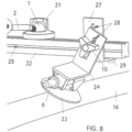
- Figs. 7 and 9 show the present invention system with at least one of rail mounts 18 having its L-shaped brackets (24, 27) at differing elevations and/or in oblique alignment with one another, and Fig.8 showing an enlarged view thereof.
- Fig. 7 is a top view of the most preferred embodiment of the present invention similar to that shown in Figs.
- FIG. 9 is a perspective view from the top of the most preferred embodiment of the present invention windshield triangulation assembly 11, setting socket 21, rail 22, and two rail mounts 18 secured to a vehicle 16 and its windshield 17, with the two L-shaped brackets (24, 27) of each rail mount 18 obliquely aligned with one another so that their quick-release suction cup attachment 23 can achieve secure attachment to differing portions of the vehicle 16, each rail mount 18 also having its suction cup 23 positioned on a different side of rail 22.
- Fig. 8 is an enlarged view of rail 22, sliding/rotatable/orientation-adjustable/height-adjustable rail mount 18, setting socket 21, and vehicle 16 previously shown in Fig. 7 .
- Figs. 10 and 11 show differing examples of use for the most preferred embodiment of the present invention system.
- Fig. 10 is a front view of a vehicle 16 with a vertically-extending windshield 17, such as a bus, recreational vehicle, or large truck, and one example of positioning for the most preferred embodiment of the present invention windshield triangulation assembly 11, setting socket 21, rail 22, and rail mounts 18, all temporarily in fixed relation to the vehicle and/or its windshield during windshield 17 replacement until the triangulation information associated with the particular alignment of windshield triangulation assembly 11 relative to the old windshield 17 and vehicle 16 is transferred to the new/replacement windshield and the new/replacement windshield 17 is lowered into the windshield opening (not shown) of vehicle 16 and against the glue (not shown) applied around the windshield opening to fix the windshield in its desired position of use once the glue sets.
- Fig. 11 is a front view of a windshield 17 attached to a vehicle 16, and three most preferred embodiments of the present invention windshield triangulation assembly 11A, 11B, and 11C each engaging the same mounted rail 22 with its own slidable setting socket 21 to demonstrate several examples of differing alternative positions in which the assembly 11 can be used to achieve triangulation for windshield replacement according to the present invention triangulation method.
- the present invention 's preferred position of use on both windshields 17 (existing and replacement) typically employs a corner of the windshield 17, it is not limited thereto., and during part of its use and in advance of existing windshield removal, the present invention windshield triangulation assembly may be aligned with the existing vehicle windshield and attached to its exterior surface to create a reproducible 3-point installer-selected alignment with portions of an existing windshield, one or more of its existing features, and/or one or more of the windshield's pre-applied markings.
- This invention relates to systems and methods used for one-person replacement of a vehicle windshield regardless of size and curvature, and which is used sequentially in particular installer-selected 3-point alignment with an existing windshield, and the same particular 3-point alignment with a replacement vehicle windshield, establishing triangulated information relating to the windshield and also relating to the vehicle, that becomes transferred to the replacement windshield for time savings and facilitated installation of the replacement windshield.
- Known and commonly used one-person windshield installation devices have one working member attached to a side window of the vehicle, but no transfer of triangulation information is involved.
- Known one-person windshield installation devices also teach a horizontal extension positioned across a replacement windshield for its lifting and movement relative to the vehicle.
- the present invention windshield triangulation assembly may be in a horizontally extending orientation across a windshield, its primary function is to translate triangulation information to the new/replacement windshield for faster and more accurate windshield installation.
- No prior art is currently known to teach a windshield installation device using transferred triangulation information from an existing windshield to facilitate installation of a replacement windshield, prevent the installer from having to move and lift the replacement windshield twice onto the vehicle, and conserve installer energy and stamina.
- the present invention maintains the entirety of a new/replacement windshield' s perimeter edge in an elevated position above a new bead of glue placed around the vehicle's windshield opening, until the installer can accurately position the replacement windshield's opposing perimeter edge onto the new bead of glue.
- the installer can then move around the vehicle and use the attached present invention to slowly lower the remaining elevated portions of the replacement windshield in a precise and controlled manner toward adjacent portions of the new bead of glue, avoiding slippage of the replacement windshield relative to the glue and achieving/preserving a good, leak-resistant seal between them.
- one or more pieces of easily removable tape may be applied to prevent replacement windshield slippage via gravity before the glue cures.
- the primary objective of this invention is to provide an improved windshield installation system and method that allows one person to install a vehicle windshield. It is also allows faster installations, eliminates the need for a dry set step, measuring, templating, and/or educated guessing, reduces the amount of training time needed for new installers, and allows an installer to work from either side of the vehicle, according to preference.
Landscapes
- Engineering & Computer Science (AREA)
- Mechanical Engineering (AREA)
- Automobile Manufacture Line, Endless Track Vehicle, Trailer (AREA)
Description
- This invention relates to systems and methods used for one-person replacement of a vehicle windshield, specifically to an elongated windshield triangulation assembly having components capable of multi-directional movement that permit its use with all vehicle windshields regardless of size and curvature, and which is used sequentially to first create a reproducible 3-point installer-selected alignment with portions of an existing windshield, one or more of its existing features or identifiable elements such as structural design features or markings, and/or one or more of the windshield's pre-applied markings, and then with the present invention windshield triangulation assembly in same 3-point alignment, the assembly becomes associated with the same windshield portions, existing features or identifiable elements such as structural design features or markings, and/or pre-applied markings on a replacement vehicle windshield, transferring the 3-point triangulated positioning obtained from the existing windshield (and also relating to the vehicle) to the replacement windshield for time savings and facilitated installation of the replacement windshield. Known and commonly used one-person windshield installation devices have one working member attached to a side window of the vehicle, but no transfer of triangulation information is involved. Known one-person windshield installation devices also teach a horizontal extension positioned across a replacement windshield for its lifting and movement relative to the vehicle. Although the present invention windshield triangulation assembly may be positioned in a horizontally extending orientation across a windshield, its primary function is to translate 3-point triangulation information from an old/existing windshield to a new/replacement windshield in any and all reproducible orientations related to the windshield for faster and more accurate windshield installation.
EP 1849634 discloses a device and method for installing a vehicle window, where a carrier frame is fitted with suckers that can be placed on segments of a motor vehicle's bodywork on both sides of window sections so as to fix the carrier frame on a motor vehicle. No prior art is known to teach a windshield installation device using transferred triangulation information from an existing windshield to facilitate installation of a new/replacement windshield, as is contemplated by the present invention. - The most preferred embodiment of the present invention to accomplish the above triangulation information transfer is characterized by an elongated windshield triangulation assembly, an elongated railing having fixed association with the vehicle needing windshield replacement via sliding/rotatable/orientation-adjustable/height-adjustable mounts, and a sliding seat (also referred to herein as a setting socket or hood stop) on the railing that receives the telescoping end of the windshield triangulation assembly after its two connected 360-degree rotation swivel clamps, each having a suction cup connection to a vehicle windshield during use, are secured in a particular installer-selected alignment against the old windshield's exterior surface. When the triangulated positioning of the windshield triangulation assembly thus created is transferred to a new/replacement windshield, needed height adjustments are made to one swivel clamp and a stop associated with the other swivel clamp, and the telescoping end of the windshield triangulation assembly is also engaged, the new windshield is easily and accurately moved into the same positioning previously occupied by the old windshield. This triangulation method accommodates windshields having any size and curvature, and installation of windshields via the present invention system and method occurs without a dry set step, measuring, templating, or educated guessing being required. Furthermore, during its use, the present invention maintains the entirety of a replacement windshield's perimeter edge in an elevated position above a new bead of glue placed around the vehicle's windshield opening, until the installer can accurately position the replacement windshield' s perimeter edge onto the new bead of glue. When a good seal is obtained, the installer can then move around the vehicle and use the attached present invention to slowly lower the remaining elevated portions of the replacement windshield in a precise and controlled manner toward adjacent portions of the new bead of glue, avoiding slippage of the replacement windshield relative to the glue and achieving/preserving a good, leak-resistant seal between them. Once the replacement windshield is fully seated on the glue, one or more pieces of easily removable tape may be applied to prevent replacement windshield slippage via gravity before the glue cures.
- During part of its use and in advance of existing windshield removal, the present invention windshield triangulation assembly is aligned with the existing vehicle windshield and attached to its exterior surface to create a reproducible 3-point installer-selected alignment with portions of an existing windshield, one or more of its existing features, and/or one or more of the windshield' s pre-applied markings. Although the present invention's preferred position of use on both windshields (existing and replacement) typically employs a corner of the windshield, it is not limited thereto. When the present invention is generally in its desired position of use relative to an existing windshield, via elevational, lateral, and/or rotational movement of some or all of present invention components (assembly, rail, and/or rail mounts) relative to one another, the present invention becomes precisely adjusted to define the existing windshield's positioning relative to its supporting vehicle, and the established 3-point triangulation information for that particular alignment and placement is ready for transfer to a replacement windshield. As mentioned before, this triangulation step avoids a later dry set step (using the replacement windshield without a new bead of glue in place around the vehicle's windshield opening for visual alignment and/or marking purposes), preventing the installer from having to move and lift the replacement windshield twice onto the vehicle, saving time, conserving installer energy and stamina, and facilitating the installation process. The most preferred embodiments of the present invention system comprise a windshield triangulation assembly with an elongated rod connected via two 360-degree rotation swivel clamps to two suction cups. However, the present invention method can be implemented with one suction cup in contact with a corner of a windshield and establishing two of the 3-points needed for triangulation, with the third point established by use of a free floating extension member or a suction cup connected to a satellite extension member. In the alternative, the primary suction cup could establish only one point of the needed 3-points needed to establish triangulation information, with the other two points established by one or two satellite extension members (free floating or with suction cup attachment). The two 360-degree rotation swivel clamps contemplated by the most preferred embodiment of the present invention provide faster and more simplified triangulations, increasing accuracy and ease of use. A ball is connected in the most preferred embodiment of the present invention to one of two opposed ends of the elongated rod via an offset angle rod, with the opposed end of the offset angle rod connected to a telescoping extension arm the length of which can be adjusted by a quick-release clamp. During triangulation use, the ball engages a setting socket (also referred to herein as 'hood stop' or 'sliding seat') releasably mounted to the vehicle in a position adjacent or near to the windshield opening, and used with the ball as a downward stop for the elongated windshield triangulation assembly. While the setting socket may comprise a simple member with one suction cup, it may also have a more complex structure that includes slidable engagement with the upper channel of a rail while suction cups become slidably engaged with the rail's opposed lower track for temporary/releasable vehicle engagement. In addition, a vertically-adjustable roof setting stop (preferably having a wheeled configuration) is preferably used with the 360-degree rotation swivel clamp positioned more remotely from the ball, and is not directly connected to the elongated rod. The roof stop does not have to maintain an alignment with the two swivel clamps. Furthermore, the present invention elongated windshield triangulation assembly and setting socket can be associated with the left side or right side of a windshield needing replacement, depending upon installer preference, aligned in part with a mirror attached to the windshield's interior surface, or otherwise placed in a particular alignment with a portion of an existing windshield and/or its pre-applied features. In addition, the setting socket also preferably has a retaining lip so that the ball on the end of the offset angle rod cannot unexpected pop out of the top receiving portion of the setting socket.
- The invention thought to be most similar in structure to that of the present invention is disclosed in
U.S. patent 7,216,411 B1 to Mayhugh (2007 ). However, in contrast to the present invention, the Mayhugh device comprises a windshield glass anchor and a separate door glass anchor for mounting on the door glass on one side of a vehicle. In addition, the Mayhugh device requires an installer to walk back and forth from one side of the vehicle to the other, at least once during the installation process. The two Mayhugh anchors are free-floating, connected by pivoting structure that includes a tube extension and a pivot rod. In contrast, the present invention in its most preferred embodiments is connected by suction cups to the same side of the windshield, and the ball on one end of its elongated rod engages a top receiving portion of a setting socket secured via a suction cup to the vehicle below its windshield opening. In addition, when using the Mayhugh invention, a windshield installer must first use a dry set step to mark windshield positioning with a piece of tape or other temporary marking means. Furthermore, after the glue is applied to the new/replacement windshield, an installer using the Mayhugh invention must rely at least in part on past installation experience to accurately place the new/replacement windshield against the vehicle without disrupting the applied glue so that a good seal can be achieved. Conversely, in the present invention precise triangulation information provided by the windshield triangulation assembly and the setting socket associated with the telescoping ball end of the assembly is translated to a new windshield. In addition, the present invention maintains the new windshield in an elevated above the vehicle's windshield opening during its initial alignment with the vehicle, after which the new/replacement windshield is precisely and accurately lowered into its desired position of use to provide a good seal against the vehicle with the pre-applied glue. Thus, the present invention has important advantages over the Mayhugh invention, and no windshield installation system or method is known to have all of the structural features and advantages of the present invention system and method.EP 1 849 634 A1method claim 1. It uses a marker pen to copy the position of the suction cups from the old to the new windscreen, creating identifiable elements on the windscreen in relation to the fixed suction cups. - The primary objective of this invention is to provide an improved windshield installation system and method that allows one person to install a vehicle windshield with precision and ease. It is also an objective of this invention to provide an improved vehicle windshield installation system and method that allows faster installations and eliminates the need for a dry set step, measuring templating, or educated guessing. A further object of this invention is to provide an improved vehicle windshield installation system and method that can be used with windshields of any size and any curvature. In addition, it is an objective of this invention to provide an improved vehicle windshield installation system and method that reduces the amount of training time needed for new installers. It is also an objective of this invention to provide an improved vehicle windshield installation system and method that allows an installer to work mainly from one side of the vehicle, and not have to move frequently back and forth from one side of the vehicle to the other. A further objective of this invention is to provide an improved vehicle windshield installation system and method that allows an installer to work from either side of a vehicle, according to preference.
- According to a first aspect of the present invention, there is provide a method as set out in
claim 1. According to a second aspect of the present invention, there is provided a system as set out inclaim 8. Optional features are presented in the dependent claims. The present invention is a vehicle windshield installation system and method allowing multiple adjustments during windshield installation to accommodate the installation of windshields having any size and any curvature. It comprises an elongated rod connected between two 360-degree rotation swivel clamps each having a suction cup connection to a vehicle windshield during use. During installation of a new/replacement windshield in a vehicle, the two swivel clamps with their suction cups are first placed in spaced-apart positions with a particular selected alignment on an existing windshield's exterior surface, thus establishing triangulation information relating to the existing windshield and/or one or more of the windshield's pre-applied markings. After triangulation is complete, the suction cups are released from the old windshield and paired in the same particular alignment with the new/replacement windshield, and glue is then applied around the windshield opening for installation of the new/replacement windshield. By placement of the ball of the windshield triangulation assembly into the receiving portion of the setting socket (hood stop) and a roof stop against a portion of the vehicle roof, the new windshield can be accurately lowered into its permanent position on the vehicle without disrupting the glue, thereby obtaining a good sealbetween the windshield and the vehicle. Installation can occur without the installer having to move from one side of the vehicle to the other, saving time, and a dry set step, templating, measuring, or educated guessing required by many prior art windshield systems and methods is eliminated. Alignment of a new windshield through use of the present invention windshield triangulation assembly is faster, easier, and more precise than with prior art systems and methods, and it works with all vehicle windshields irrespective of size and curvature. -
-
Fig. 1 is a perspective view from the side of the most preferred embodiment of the present invention windshield triangulation assembly showing its elongated rod connected between two 360-degree rotation swivel clamps each having a suction cup, the rod including one telescoping end component with an angled rod and ball, in addition to an optional height-adjustable stop having a wheeled configuration associated with the swivel clamp positioned most remotely from the ball. -
Fig. 2 is an enlarged perspective view of the height-adjustable stop and swivel clamp shown inFig. 1 , the height-adjustable stop secured to the swivel clamp via an attachment plate and a non-rotating clamp having hand-tightened adjustment means. -
Fig. 3 is side view from the top and shows one example of positioning for the most preferred embodiment of the present invention windshield triangulation assembly previously illustrated inFigs. 1-2 , wherein the assembly is attached to one side of a vehicle windshield and the ball on one of its ends engages the receiving top portion of a setting socket slidingly engaged with a rail temporarily attached by an easily releasable mount to the vehicle's exterior surface below its windshield opening, the wheeled stop associated with the opposing end of the assembly also engaging a portion of the vehicle's exterior roof surface above the windshield opening, and both of the assembly's suction cups, each connected to a different one of the swivel clamps supporting the elongated rod connected between them, the suction cups having similar positioning on the windshield in contact with the same side edge thereof, one near to the roof stop and the other near to the hood stop, the assembly's two suction cups establishing precise triangulation information for the attached windshield. -
Fig. 4 is an enlarged perspective view of the most preferred embodiment of the present invention sliding/rotatable/orientation-adjustable/height-adjustable rail mount shown inFig. 3 . -
Fig. 5 is a front view of the most preferred embodiment of the present invention windshield triangulation assembly temporarily secured to a windshield in a position similar to that shown inFig. 3 , a setting socket slidingly engaged with a rail temporarily attached to the vehicle below its windshield opening and supporting the ball end of the assembly, the rail supported by two sliding/rotatable/orientation-adjustable/height-adjustable mounts with quick-release suction cup attachment, and the rail having an optional central bumper below it and extending toward the vehicle's exterior surface. -
Fig. 6 is a side view of the most preferred embodiment of the present invention similar to that shown inFigs. 3 and5 , but without the optional bumper situated beneath the rail, the two L-shaped brackets supporting the near end of the rail in alignment with one another and not obliquely rotated with respect to one another. -
Fig. 7 is a top view of the most preferred embodiment of the present invention similar to that shown inFigs. 3 ,5 , and6 , with one end of its windshield triangulation assembly seated in a setting socket slidingly engaged with the rail and the rail mount next to it having its two L-shaped brackets rotated to provide obliquely alignment with respect to one another, and also set at different elevations, so that its quick-release suction cup attachment can achieve secure attachment to the side of a vehicle, or other potentially non-level surface, instead of a relatively flattened portion of a vehicle hood. -
Fig. 8 is an enlarged view of the rail, sliding/rotatable/orientation-adjustable/height-adjustable rail mount, setting socket, and vehicle previously shown inFig. 7 . -
Fig. 9 is a perspective view from the top of the most preferred embodiment of the present invention windshield triangulation assembly, setting socket, rail, and two rail mounts secured to a vehicle and its windshield, with the two L-shaped brackets of each rail mount obliquely aligned with one another so that their quick-release suction cup attachment can achieve secure attachment to differing portions of the vehicle, each rail mount also having its suction cup positioned on a different side of the rail. -
Fig. 10 is a front view of a vehicle with a vertically-extending windshield, such as a bus, recreational vehicle, or large truck, and the most preferred embodiment of the present invention windshield triangulation assembly, setting socket, rail, and rail mounts, temporarily secured to the vehicle and its windshield. -
Fig. 11 is a front view of a windshield attached to a vehicle, and three most preferred embodiments of the present invention windshield triangulation assembly each engaging the same mounted rail with its own slidable setting socket to demonstrate several examples of differing alternative positions in which the assembly can be used to achieve triangulation for windshield replacement. - The most preferred embodiment of the present invention system and method is shown in
Figs. 1-11 and comprises a vehiclewindshield triangulation assembly 11 and method allowing multiple adjustments duringwindshield 17 installation into avehicle 16 and accommodating the installation ofvehicle windshields 17 having any size and any curvature. For fast and efficient one-person vehicle windshield 16 installation,windshield triangulation assembly 11 preferably comprises anelongated rod 5 connected via two 360-degree rotation swivel clamps 7 each having an upright post suction cups (6, 8, withcomponent 6 being pump assembly for suction cup 8). Thesuction cup 8 and pumpassembly 6 may be considered as a suction cup assembly. However, use ofsuction cup 8 in association with anupright post 6 is not critical, and many other easily-releasable suction cups are easily substituted. During installation of a new/replacement windshield 17 in avehicle 16,Figs. 1 ,3 , and5-7 show the two upright post suction cups (6, 8) in one preferred position of use and in spaced-apart aligned positions along one side (and on top of) thewindshield 17. Furthermore, although examples of particular alignment selections forwindshield triangulation assembly 11 are shown inFig. 11 , additional particular alignment selections forwindshield triangulation assembly 11 are also contemplated. The most preferred embodiment of the present invention system also has aball 1 connected to one end of theelongated rod 5 via an offsetangle rod 2 -
Fig. 1 is a perspective view from the side of the most preferred embodiment of the present inventionwindshield triangulation assembly 11 showing itselongated rod 5 connected between two 360-degree rotation swivel clamps 7 each having asuction cup 8, therod 5 including onetelescoping end component 3 with anangled rod 2 andball 1, in addition to an optional height-adjustable stop (12. 13) having a wheeled configuration associated with theswivel clamp 7 positioned most remotely fromball 1. In contrast,Fig. 2 is an enlarged perspective view of the height-adjustable stop (12, 13) and oneswivel clamp 7 shown inFig. 1 , the height-adjustable stop (12, 13) secured to theswivel clamp 7 via anattachment plate 14 and a non-rotating clamp portion ofplate 14 having hand-tightened adjustment means 10. The configuration shown for adjustment means 10 provides just one example thereof, and should not be considered as limited thereto. WhileFig. 2 further shows preferred structure for height-adjustable stop 12/13, fastener holes 15, and attachment plate and clamp 14, it is not contemplated for the number, size, configuration, relative size, and placement of fastener holes 15 to be limited to that shown inFig. 2 . -
Figs. 3 and5-7 showwindshield triangulation assembly 11 secured to awindshield 17 and associated with a settingsocket 21,rail 22, and rail mounts 18.Fig. 3 is side view from the top and shows one example of positioning for the most preferred embodiment of the present inventionwindshield triangulation assembly 11 previously illustrated inFigs. 1-2 , whereinassembly 11 is attached to one side of avehicle windshield 17 and theball 1 on one of its ends engages the receiving top portion of a settingsocket 21 slidingly engaged with arail 22 temporarily attached by an easilyreleasable mount 18 to the exterior surface of avehicle 16 below its windshield opening, the wheeled stop (12, 13) associated with the opposing end ofassembly 11 also engaging a portion of the exterior roof surface ofvehicle 16 above the windshield opening. Each of thesuction cups 8 ofassembly 11 are connected to a different one of the swivel clamps 7 supporting theelongated rod 5 connected between them, thesuction cups 8 having similar positioning on the windshield in contact with the same side edge thereof, one near to the roof stop (12, 13) and the other near to the hood stop (21), the assembly's twosuction cups 8 andball 1 establishing precise triangulation information for the attachedwindshield 17. One of the suction cups can be considered to be an alignment guide. In contrast,Fig. 4 is an enlarged perspective view of the most preferred embodiment of present invention sliding/rotatable/orientation-adjustable/height-adjustable rail mount 18 shown inFig. 3 and having two L-shapedbrackets knob 10 through height adjustment slots in vertically-extending portion of eachbracket 24/27. As also seen inFig. 4 , L-shapedbracket 27 is supporting arail 22 withlongitudinal channels 25 shown on each of its four faces. Arubber stop 29 is shown under L-shapedbracket 27 to protectvehicle 16 paint and support weight. Thenumber 26 inFig. 4 identifies the swivel connection of L-shapedbracket 27 and means of sliding and rotatable connection to rail 22. The L-shapedbracket 24 inFig. 4 is connected to asuction cup 23 and apump assembly 6 for securely attachingsuction cup 23 to the painted surface ofvehicle 16.Fig. 5 is a front view of the most preferred embodiment of the present inventionwindshield triangulation assembly 11 temporarily secured to awindshield 17 in a position similar to that shown inFig. 3 , a settingsocket 21 slidingly engaged with arail 22 temporarily attached to thevehicle 16 below its windshield opening and supporting theball 1 end of theassembly 11, therail 22 supported by two sliding/rotatable/orientation-adjustable/height-adjustable mounts 18 each with quick-releasesuction cup attachment 23, and therail 22 having an optionalcentral bumper 30 below it and extending toward the exterior surface ofvehicle 16.Fig. 6 is a side view of the most preferred embodiment of the present invention similar to that shown inFigs. 3 and5 , but without theoptional bumper 30 situated beneath therail 22, the two L-shaped brackets (24 and 27) supporting the near end ofrail 22 in alignment with one another and not obliquely rotated with respect to one another. -
Figs. 7 and9 show the present invention system with at least one of rail mounts 18 having its L-shaped brackets (24, 27) at differing elevations and/or in oblique alignment with one another, andFig.8 showing an enlarged view thereof.Fig. 7 is a top view of the most preferred embodiment of the present invention similar to that shown inFigs. 3 ,5 , and6 , with one end of itswindshield triangulation assembly 11 seated in a settingsocket 21 slidingly engaged with therail 22 and therail mount 18 next to it having its two L-shaped brackets (24, 27) rotated to provide oblique alignment with respect to one another, and also set at different elevations, so that its quick-releasesuction cup attachment 23 can achieve secure attachment to the side of avehicle 16, or other potentially non-level surface ofvehicle 16, instead of a relatively flattened portion of the hood ofvehicle 16. In contrast,Fig. 9 is a perspective view from the top of the most preferred embodiment of the present inventionwindshield triangulation assembly 11, settingsocket 21,rail 22, and two rail mounts 18 secured to avehicle 16 and itswindshield 17, with the two L-shaped brackets (24, 27) of eachrail mount 18 obliquely aligned with one another so that their quick-releasesuction cup attachment 23 can achieve secure attachment to differing portions of thevehicle 16, eachrail mount 18 also having itssuction cup 23 positioned on a different side ofrail 22.Fig. 8 is an enlarged view ofrail 22, sliding/rotatable/orientation-adjustable/height-adjustable rail mount 18, settingsocket 21, andvehicle 16 previously shown inFig. 7 . -
Figs. 10 and11 show differing examples of use for the most preferred embodiment of the present invention system.Fig. 10 is a front view of avehicle 16 with a vertically-extendingwindshield 17, such as a bus, recreational vehicle, or large truck, and one example of positioning for the most preferred embodiment of the present inventionwindshield triangulation assembly 11, settingsocket 21,rail 22, and rail mounts 18, all temporarily in fixed relation to the vehicle and/or its windshield duringwindshield 17 replacement until the triangulation information associated with the particular alignment ofwindshield triangulation assembly 11 relative to theold windshield 17 andvehicle 16 is transferred to the new/replacement windshield and the new/replacement windshield 17 is lowered into the windshield opening (not shown) ofvehicle 16 and against the glue (not shown) applied around the windshield opening to fix the windshield in its desired position of use once the glue sets. In the alternative,Fig. 11 is a front view of awindshield 17 attached to avehicle 16, and three most preferred embodiments of the present invention windshield triangulation assembly 11A, 11B, and 11C each engaging the same mountedrail 22 with its ownslidable setting socket 21 to demonstrate several examples of differing alternative positions in which theassembly 11 can be used to achieve triangulation for windshield replacement according to the present invention triangulation method. Although the present invention's preferred position of use on both windshields 17 (existing and replacement) typically employs a corner of thewindshield 17, it is not limited thereto., and during part of its use and in advance of existing windshield removal, the present invention windshield triangulation assembly may be aligned with the existing vehicle windshield and attached to its exterior surface to create a reproducible 3-point installer-selected alignment with portions of an existing windshield, one or more of its existing features, and/or one or more of the windshield's pre-applied markings. - While the written description of the invention herein is intended to enable one of ordinary skill to make and use its best mode, it should also be appreciated that the invention disclosure only provides examples of specific embodiments and methods, and many variations, combinations, and equivalents also exist which are not specifically mentioned. The present invention should therefore not be considered as limited to the above-described embodiments, methods, and examples, but instead encompassing all embodiments and methods identified in the accompanying claims.
- This invention relates to systems and methods used for one-person replacement of a vehicle windshield regardless of size and curvature, and which is used sequentially in particular installer-selected 3-point alignment with an existing windshield, and the same particular 3-point alignment with a replacement vehicle windshield, establishing triangulated information relating to the windshield and also relating to the vehicle, that becomes transferred to the replacement windshield for time savings and facilitated installation of the replacement windshield. Known and commonly used one-person windshield installation devices have one working member attached to a side window of the vehicle, but no transfer of triangulation information is involved. Known one-person windshield installation devices also teach a horizontal extension positioned across a replacement windshield for its lifting and movement relative to the vehicle. Although the present invention windshield triangulation assembly may be in a horizontally extending orientation across a windshield, its primary function is to translate triangulation information to the new/replacement windshield for faster and more accurate windshield installation. No prior art is currently known to teach a windshield installation device using transferred triangulation information from an existing windshield to facilitate installation of a replacement windshield, prevent the installer from having to move and lift the replacement windshield twice onto the vehicle, and conserve installer energy and stamina.
- Also during its use, the present invention maintains the entirety of a new/replacement windshield' s perimeter edge in an elevated position above a new bead of glue placed around the vehicle's windshield opening, until the installer can accurately position the replacement windshield's opposing perimeter edge onto the new bead of glue. When a good seal is obtained, the installer can then move around the vehicle and use the attached present invention to slowly lower the remaining elevated portions of the replacement windshield in a precise and controlled manner toward adjacent portions of the new bead of glue, avoiding slippage of the replacement windshield relative to the glue and achieving/preserving a good, leak-resistant seal between them. Once the replacement windshield is fully seated on the glue, one or more pieces of easily removable tape may be applied to prevent replacement windshield slippage via gravity before the glue cures. The primary objective of this invention is to provide an improved windshield installation system and method that allows one person to install a vehicle windshield. It is also allows faster installations, eliminates the need for a dry set step, measuring, templating, and/or educated guessing, reduces the amount of training time needed for new installers, and allows an installer to work from either side of the vehicle, according to preference.
Claims (15)
- A triangulation method for replacing the windshield (17) of a vehicle (16), said method is characterized by the steps of:providing a vehicle (16) with an existing windshield (17) in a windshield opening, said windshield having a plurality of identifiable elements selected from a group consisting of structural design features, markings, and pre-applied features, a replacement windshield (17) for said vehicle, at least one suction cup assembly including a suction cup (8) and pump assembly (6), and at least one alignment guide (8) in association with said at least one suction cup assembly (6, 8) for providing a windshield triangulation assembly;selecting three of said identifiable elements;securing said at least one suction cup assembly to said existing windshield (17) adjacent to at least one of said selected identifiable elements and also moving said at least one alignment guide relative to said existing windshield and affixing each said at least one alignment guide adjacent to a different one of said selected identifiable elements, thereby creating reproducible 3-point triangulation alignment information in the windshield triangulation assembly;removing said at least one suction cup assembly and at least one alignment guide from said existing windshield while preserving said reproducible 3-point triangulation alignment information in the windshield triangulation assembly; andapplying said at least one suction cup assembly and at least one alignment guide to said replacement windshield (17), transferring said reproducible 3-point triangulation alignment information to said replacement windshield via the windshield triangulation assembly, wherein said transferred reproducible 3-point triangulation alignment information allows said replacement windshield to be accurately installed in said windshield opening of said vehicle.
- The method of claim 1 wherein said at least one alignment guide includes a suction cup (8).
- The method of claim 2 further characterized by the steps of providing an elongated rod, and connecting said suction cups with said elongated rod (5).
- The method of claim 3 wherein said elongated rod (5) is further characterized on one end by a telescoping end component (3) having an angled rod (2) and connected ball (1).
- The method of claim 4 further characterized by the step of providing a rail (22), a plurality of rail mounts (18), and a setting socket (21), the step of using said rail mounts to support said rail on said vehicle, the step of supporting said setting socket on said rail in a position to receive said ball (1), optionally wherein said setting socket has a retaining lip for the ball.
- The method of claim 5 wherein said rail (22) is further characterized (a) by a plurality of longitudinal channels (25) in which said rail mounts (18) and said setting socket (21) are slidably engaged; or (b) by opposing sides and said rail mounts (18) are each further characterized by at least two L-shaped brackets (24, 27) rotatable relative to said rail for movement from one of said opposing sides to the other, said L-shaped brackets also being orientation-adjustable with respect to one another when connected together and height-adjustable with respect to one another when connected together.
- The method of claim 5 further characterized by the step of providing an elevation adjustable stop (12, 13), the step of associating said elevation adjustable stop with the one of said suction cups (8) remote from said ball (1), and the step of changing the elevation of said elongated rod (5) via elevation change of stop and the one of said suction cups adjacent to said ball, optionally wherein said stop has a wheeled configuration.
- A triangulation installation system (11) for use in expedited and accurate replacement of an existing vehicle windshield (17) with identifiable elements with a new windshield (17) having the same identifiable elements, said system being characterized by two 360-degree rotation swivel clamps (7) connected by an elongated rod (5), wherein in use said two swivel clamps are securable by suction cups (8) adjacent to three of the identifiable elements to create reproducible 3-point triangulation alignment information, in use said reproducible 3-point triangulation alignment information being preserved following removal of the suction cups from the existing windshield and application to the replacement windshield for transferring said reproducible 3-point triangulation alignment information to the replacement windshield for accurate instalment of the replacement windshield.
- The system (11) of claim 8 wherein said elongated rod (5) is further characterized on one end by a telescoping component (3) having an angled rod (2) and connected ball (1).
- The system (11) of claim 9 wherein said telescoping component (3) is further characterized by 360-degree rotation.
- The system (11) of claim 9 further characterized by a rail (22), a plurality of rail mounts (18) supporting said rail, and a setting socket (21) supported on said rail in a position to receive said ball (1), optionally wherein said setting socket is further characterized by a retaining lip for said ball.
- The system (11) of claim 11 wherein said rail (22) is further characterized by a plurality of longitudinal channels (25) in which said rail mounts (18) and said setting socket (21) are slidably engaged.
- The system (11) of claim 11 wherein said rail (22) is further characterized by opposing sides and said rail mounts (18) are each further characterized by at least two L-shaped brackets (24, 27) rotatable relative to said rail for movement from one of said opposing sides to the other, said L-shaped brackets also being orientation-adjustable with respect to one another when connected together and height-adjustable with respect to one another when connected together.
- The system (11) of claim 13 said L-shaped brackets (24, 27) further characterized by use in pairs, and one of said L-shaped brackets in each said pair associated with a bottom stop (29) and the other one of said L-shaped brackets in each said pair associated with a bottom suction cup (23).
- The system (11) of claim 10 further characterized by an elevation adjustable stop (12, 13) associated with the one of said suction cups (8) remote from said ball (1), allowing a change in elevation of said elongated rod (5) via elevation change of said stop and the one of said suction cups adjacent to said ball, optionally wherein said stop has a wheeled configuration.
Applications Claiming Priority (2)
| Application Number | Priority Date | Filing Date | Title |
|---|---|---|---|
| US201662354403P | 2016-06-24 | 2016-06-24 | |
| PCT/US2017/039340 WO2017223573A1 (en) | 2016-06-24 | 2017-06-26 | Windshield installation system and triangulation method |
Publications (4)
| Publication Number | Publication Date |
|---|---|
| EP3475107A1 EP3475107A1 (en) | 2019-05-01 |
| EP3475107A4 EP3475107A4 (en) | 2020-02-19 |
| EP3475107C0 EP3475107C0 (en) | 2024-03-13 |
| EP3475107B1 true EP3475107B1 (en) | 2024-03-13 |
Family
ID=60783968
Family Applications (1)
| Application Number | Title | Priority Date | Filing Date |
|---|---|---|---|
| EP17816382.0A Active EP3475107B1 (en) | 2016-06-24 | 2017-06-26 | Windshield installation system and triangulation method |
Country Status (4)
| Country | Link |
|---|---|
| US (1) | US11529849B2 (en) |
| EP (1) | EP3475107B1 (en) |
| CA (1) | CA3068412A1 (en) |
| WO (1) | WO2017223573A1 (en) |
Families Citing this family (6)
| Publication number | Priority date | Publication date | Assignee | Title |
|---|---|---|---|---|
| CN112025366A (en) * | 2020-08-20 | 2020-12-04 | 佛山职业技术学院 | Sucking disc formula multifunctional clamp |
| CN112502397A (en) * | 2020-11-26 | 2021-03-16 | 浙江亚厦装饰股份有限公司 | Sucker device with internal corner square measuring guiding rule |
| CA3107293A1 (en) * | 2021-01-27 | 2022-07-27 | Eric Rolseth | Modular accessory for panel adherence devices |
| CN114769885B (en) * | 2022-03-31 | 2022-11-01 | 南京萃智激光应用技术研究院有限公司 | Laser precision etching equipment |
| USD1057531S1 (en) * | 2023-03-16 | 2025-01-14 | Yuehua Wang | Windshield repair tool |
| CN120027749B (en) * | 2025-04-21 | 2025-07-25 | 广东省世通仪器检测服务有限公司 | Socket size detection device and detection method |
Citations (2)
| Publication number | Priority date | Publication date | Assignee | Title |
|---|---|---|---|---|
| FR2828826B1 (en) * | 2001-08-23 | 2003-10-31 | Jean Luc Domeon | GUIDING DEVICE FOR THE INSTALLATION OF GLUE WINDSHIELDS |
| EP1849634B1 (en) * | 2006-04-27 | 2008-12-10 | ProGlass GmbH | Device and method for installing a vehicle window |
Family Cites Families (14)
| Publication number | Priority date | Publication date | Assignee | Title |
|---|---|---|---|---|
| US4998711A (en) * | 1990-02-23 | 1991-03-12 | Borg Donald M | Workpiece holder and method of installing a vehicle windshield therewith |
| US5292045A (en) * | 1992-07-30 | 1994-03-08 | Mandel F Howard | Multipurpose rack for convertible top motor vehicles |
| GB2273517B (en) * | 1992-12-21 | 1996-04-03 | Autoglass Ltd | Apparatus and method for installing windows |
| US5626261A (en) * | 1995-10-25 | 1997-05-06 | Glass Technology Inc. | Resin injector guide for windshield crack repair |
| EP0928265B1 (en) * | 1996-09-25 | 2004-09-08 | Belron International Nv | Windscreen replacement apparatus |
| US6616800B2 (en) * | 2001-03-05 | 2003-09-09 | Rolf O. Eriksson | Method and device for removing windshields |
| US7310865B2 (en) * | 2004-02-17 | 2007-12-25 | General Motors Corporation | Gap setting tool and method of operating same |
| US7216411B1 (en) | 2004-09-23 | 2007-05-15 | Mayhugh Kent R | Method for enabling a single technician to install a windshield into a vehicle |
| US20060156533A1 (en) * | 2004-09-23 | 2006-07-20 | Mayhugh Kent R | Single technician large windshield installation tool |
| US7322092B2 (en) * | 2005-11-14 | 2008-01-29 | Aegis Tools International, Inc. | Windshield installation device and method of use |
| PL2274196T3 (en) * | 2008-04-23 | 2013-09-30 | Aegis Tools Int Inc | Windshield installation device and method of use |
| FR2952023B1 (en) * | 2009-11-02 | 2011-11-11 | Robotic Consulting | DEVICE FOR ASSISTING THE INSTALLATION OF A WINDSCREEN OR THE LIKE |
| GB201018558D0 (en) * | 2010-11-03 | 2010-12-15 | Belron Hungary Kft Zug Branch | Windscreen installation apparatus and method |
| US20150360737A1 (en) * | 2014-06-12 | 2015-12-17 | Richard E. Brummett | Vehicle glass removal and replacement system and method |
-
2017
- 2017-06-26 WO PCT/US2017/039340 patent/WO2017223573A1/en not_active Ceased
- 2017-06-26 CA CA3068412A patent/CA3068412A1/en active Pending
- 2017-06-26 EP EP17816382.0A patent/EP3475107B1/en active Active
- 2017-06-26 US US16/312,289 patent/US11529849B2/en active Active
Patent Citations (2)
| Publication number | Priority date | Publication date | Assignee | Title |
|---|---|---|---|---|
| FR2828826B1 (en) * | 2001-08-23 | 2003-10-31 | Jean Luc Domeon | GUIDING DEVICE FOR THE INSTALLATION OF GLUE WINDSHIELDS |
| EP1849634B1 (en) * | 2006-04-27 | 2008-12-10 | ProGlass GmbH | Device and method for installing a vehicle window |
Also Published As
| Publication number | Publication date |
|---|---|
| EP3475107C0 (en) | 2024-03-13 |
| CA3068412A1 (en) | 2017-12-28 |
| US11529849B2 (en) | 2022-12-20 |
| US20190232761A1 (en) | 2019-08-01 |
| EP3475107A4 (en) | 2020-02-19 |
| WO2017223573A1 (en) | 2017-12-28 |
| EP3475107A1 (en) | 2019-05-01 |
Similar Documents
| Publication | Publication Date | Title |
|---|---|---|
| US11529849B2 (en) | Windshield installation system and triangulation method | |
| US7039995B2 (en) | Windshield removal and replacement apparatus | |
| US6220390B1 (en) | Rooftop scaffolding | |
| WO2008036532B1 (en) | Dockable trolley for vehicle frame-straightening bench | |
| CN102079043A (en) | Detachable support device for a car door | |
| US5732527A (en) | Panel lift apparatus | |
| US20180281693A1 (en) | Road finishing machine with retainer device for supporting and positioning a sensor unit | |
| CN113696118A (en) | Vehicle door assembling tool | |
| GB2273517A (en) | Apparatus and method for installing vehicle windows | |
| US5085415A (en) | Windshield installation tool | |
| CN113772545A (en) | Vehicle door assembling lifting appliance and vehicle door assembling device | |
| US20060010828A1 (en) | Siding installation tool | |
| EP0928265B1 (en) | Windscreen replacement apparatus | |
| EP2140081B1 (en) | Stair handrail mounting bracket | |
| CN211548687U (en) | Interior decoration scaffold convenient to remove | |
| US20200256082A1 (en) | Roof shade apparatus | |
| CN214837387U (en) | Convenient erection equipment that industry fan was used | |
| US20210337988A1 (en) | Wall decorative object hanger | |
| AU740149B2 (en) | Windscreen replacement apparatus | |
| CN210597309U (en) | Vertical supporting pile verticality adjusting platform | |
| CN214942340U (en) | Wall and column formwork height adjusting device | |
| CN220808570U (en) | Three-dimensional adjustable rolling device for automobile skylight glass sealing strip | |
| CN220792540U (en) | High fixing device of laser level | |
| CN220842396U (en) | Support adjustment locking structure | |
| CN222201130U (en) | Bridge concrete guardrail positioner that punches |
Legal Events
| Date | Code | Title | Description |
|---|---|---|---|
| STAA | Information on the status of an ep patent application or granted ep patent |
Free format text: STATUS: THE INTERNATIONAL PUBLICATION HAS BEEN MADE |
|
| PUAI | Public reference made under article 153(3) epc to a published international application that has entered the european phase |
Free format text: ORIGINAL CODE: 0009012 |
|
| STAA | Information on the status of an ep patent application or granted ep patent |
Free format text: STATUS: REQUEST FOR EXAMINATION WAS MADE |
|
| 17P | Request for examination filed |
Effective date: 20181211 |
|
| AK | Designated contracting states |
Kind code of ref document: A1 Designated state(s): AL AT BE BG CH CY CZ DE DK EE ES FI FR GB GR HR HU IE IS IT LI LT LU LV MC MK MT NL NO PL PT RO RS SE SI SK SM TR |
|
| AX | Request for extension of the european patent |
Extension state: BA ME |
|
| DAV | Request for validation of the european patent (deleted) | ||
| DAX | Request for extension of the european patent (deleted) | ||
| A4 | Supplementary search report drawn up and despatched |
Effective date: 20200121 |
|
| RIC1 | Information provided on ipc code assigned before grant |
Ipc: B60J 1/00 20060101ALI20200115BHEP Ipc: B60J 1/02 20060101AFI20200115BHEP |
|
| STAA | Information on the status of an ep patent application or granted ep patent |
Free format text: STATUS: EXAMINATION IS IN PROGRESS |
|
| 17Q | First examination report despatched |
Effective date: 20210319 |
|
| GRAP | Despatch of communication of intention to grant a patent |
Free format text: ORIGINAL CODE: EPIDOSNIGR1 |
|
| STAA | Information on the status of an ep patent application or granted ep patent |
Free format text: STATUS: GRANT OF PATENT IS INTENDED |
|
| INTG | Intention to grant announced |
Effective date: 20221209 |
|
| RAP3 | Party data changed (applicant data changed or rights of an application transferred) |
Owner name: FOSS, CHRISTIAN, M. |
|
| RIN1 | Information on inventor provided before grant (corrected) |
Inventor name: FOSS, CHRISTIAN, M. |
|
| GRAS | Grant fee paid |
Free format text: ORIGINAL CODE: EPIDOSNIGR3 |
|
| GRAA | (expected) grant |
Free format text: ORIGINAL CODE: 0009210 |
|
| STAA | Information on the status of an ep patent application or granted ep patent |
Free format text: STATUS: THE PATENT HAS BEEN GRANTED |
|
| AK | Designated contracting states |
Kind code of ref document: B1 Designated state(s): AL AT BE BG CH CY CZ DE DK EE ES FI FR GB GR HR HU IE IS IT LI LT LU LV MC MK MT NL NO PL PT RO RS SE SI SK SM TR |
|
| REG | Reference to a national code |
Ref country code: GB Ref legal event code: FG4D |
|
| REG | Reference to a national code |
Ref country code: CH Ref legal event code: EP |
|
| REG | Reference to a national code |
Ref country code: DE Ref legal event code: R096 Ref document number: 602017080031 Country of ref document: DE |
|
| REG | Reference to a national code |
Ref country code: IE Ref legal event code: FG4D |
|
| U01 | Request for unitary effect filed |
Effective date: 20240411 |
|
| U07 | Unitary effect registered |
Designated state(s): AT BE BG DE DK EE FI FR IT LT LU LV MT NL PT SE SI Effective date: 20240418 |
|
| PG25 | Lapsed in a contracting state [announced via postgrant information from national office to epo] |
Ref country code: GR Free format text: LAPSE BECAUSE OF FAILURE TO SUBMIT A TRANSLATION OF THE DESCRIPTION OR TO PAY THE FEE WITHIN THE PRESCRIBED TIME-LIMIT Effective date: 20240614 |
|
| PG25 | Lapsed in a contracting state [announced via postgrant information from national office to epo] |
Ref country code: RS Free format text: LAPSE BECAUSE OF FAILURE TO SUBMIT A TRANSLATION OF THE DESCRIPTION OR TO PAY THE FEE WITHIN THE PRESCRIBED TIME-LIMIT Effective date: 20240613 Ref country code: HR Free format text: LAPSE BECAUSE OF FAILURE TO SUBMIT A TRANSLATION OF THE DESCRIPTION OR TO PAY THE FEE WITHIN THE PRESCRIBED TIME-LIMIT Effective date: 20240313 |
|
| PG25 | Lapsed in a contracting state [announced via postgrant information from national office to epo] |
Ref country code: ES Free format text: LAPSE BECAUSE OF FAILURE TO SUBMIT A TRANSLATION OF THE DESCRIPTION OR TO PAY THE FEE WITHIN THE PRESCRIBED TIME-LIMIT Effective date: 20240313 |
|
| PG25 | Lapsed in a contracting state [announced via postgrant information from national office to epo] |
Ref country code: RS Free format text: LAPSE BECAUSE OF FAILURE TO SUBMIT A TRANSLATION OF THE DESCRIPTION OR TO PAY THE FEE WITHIN THE PRESCRIBED TIME-LIMIT Effective date: 20240613 Ref country code: NO Free format text: LAPSE BECAUSE OF FAILURE TO SUBMIT A TRANSLATION OF THE DESCRIPTION OR TO PAY THE FEE WITHIN THE PRESCRIBED TIME-LIMIT Effective date: 20240613 Ref country code: HR Free format text: LAPSE BECAUSE OF FAILURE TO SUBMIT A TRANSLATION OF THE DESCRIPTION OR TO PAY THE FEE WITHIN THE PRESCRIBED TIME-LIMIT Effective date: 20240313 Ref country code: GR Free format text: LAPSE BECAUSE OF FAILURE TO SUBMIT A TRANSLATION OF THE DESCRIPTION OR TO PAY THE FEE WITHIN THE PRESCRIBED TIME-LIMIT Effective date: 20240614 Ref country code: ES Free format text: LAPSE BECAUSE OF FAILURE TO SUBMIT A TRANSLATION OF THE DESCRIPTION OR TO PAY THE FEE WITHIN THE PRESCRIBED TIME-LIMIT Effective date: 20240313 |
|
| PG25 | Lapsed in a contracting state [announced via postgrant information from national office to epo] |
Ref country code: IS Free format text: LAPSE BECAUSE OF FAILURE TO SUBMIT A TRANSLATION OF THE DESCRIPTION OR TO PAY THE FEE WITHIN THE PRESCRIBED TIME-LIMIT Effective date: 20240713 |
|
| PG25 | Lapsed in a contracting state [announced via postgrant information from national office to epo] |
Ref country code: SM Free format text: LAPSE BECAUSE OF FAILURE TO SUBMIT A TRANSLATION OF THE DESCRIPTION OR TO PAY THE FEE WITHIN THE PRESCRIBED TIME-LIMIT Effective date: 20240313 |
|
| PG25 | Lapsed in a contracting state [announced via postgrant information from national office to epo] |
Ref country code: CZ Free format text: LAPSE BECAUSE OF FAILURE TO SUBMIT A TRANSLATION OF THE DESCRIPTION OR TO PAY THE FEE WITHIN THE PRESCRIBED TIME-LIMIT Effective date: 20240313 |
|
| PG25 | Lapsed in a contracting state [announced via postgrant information from national office to epo] |
Ref country code: PL Free format text: LAPSE BECAUSE OF FAILURE TO SUBMIT A TRANSLATION OF THE DESCRIPTION OR TO PAY THE FEE WITHIN THE PRESCRIBED TIME-LIMIT Effective date: 20240313 |
|
| PG25 | Lapsed in a contracting state [announced via postgrant information from national office to epo] |
Ref country code: SK Free format text: LAPSE BECAUSE OF FAILURE TO SUBMIT A TRANSLATION OF THE DESCRIPTION OR TO PAY THE FEE WITHIN THE PRESCRIBED TIME-LIMIT Effective date: 20240313 |
|
| PG25 | Lapsed in a contracting state [announced via postgrant information from national office to epo] |
Ref country code: SM Free format text: LAPSE BECAUSE OF FAILURE TO SUBMIT A TRANSLATION OF THE DESCRIPTION OR TO PAY THE FEE WITHIN THE PRESCRIBED TIME-LIMIT Effective date: 20240313 Ref country code: SK Free format text: LAPSE BECAUSE OF FAILURE TO SUBMIT A TRANSLATION OF THE DESCRIPTION OR TO PAY THE FEE WITHIN THE PRESCRIBED TIME-LIMIT Effective date: 20240313 Ref country code: RO Free format text: LAPSE BECAUSE OF FAILURE TO SUBMIT A TRANSLATION OF THE DESCRIPTION OR TO PAY THE FEE WITHIN THE PRESCRIBED TIME-LIMIT Effective date: 20240313 Ref country code: PL Free format text: LAPSE BECAUSE OF FAILURE TO SUBMIT A TRANSLATION OF THE DESCRIPTION OR TO PAY THE FEE WITHIN THE PRESCRIBED TIME-LIMIT Effective date: 20240313 Ref country code: IS Free format text: LAPSE BECAUSE OF FAILURE TO SUBMIT A TRANSLATION OF THE DESCRIPTION OR TO PAY THE FEE WITHIN THE PRESCRIBED TIME-LIMIT Effective date: 20240713 Ref country code: CZ Free format text: LAPSE BECAUSE OF FAILURE TO SUBMIT A TRANSLATION OF THE DESCRIPTION OR TO PAY THE FEE WITHIN THE PRESCRIBED TIME-LIMIT Effective date: 20240313 |
|
| REG | Reference to a national code |
Ref country code: DE Ref legal event code: R097 Ref document number: 602017080031 Country of ref document: DE |
|
| U21 | Renewal fee for the european patent with unitary effect paid with additional fee |
Year of fee payment: 8 Effective date: 20241128 |
|
| PLBE | No opposition filed within time limit |
Free format text: ORIGINAL CODE: 0009261 |
|
| STAA | Information on the status of an ep patent application or granted ep patent |
Free format text: STATUS: NO OPPOSITION FILED WITHIN TIME LIMIT |
|
| PG25 | Lapsed in a contracting state [announced via postgrant information from national office to epo] |
Ref country code: MC Free format text: LAPSE BECAUSE OF FAILURE TO SUBMIT A TRANSLATION OF THE DESCRIPTION OR TO PAY THE FEE WITHIN THE PRESCRIBED TIME-LIMIT Effective date: 20240313 |
|
| REG | Reference to a national code |
Ref country code: CH Ref legal event code: PL |
|
| 26N | No opposition filed |
Effective date: 20241216 |
|
| U1N | Appointed representative for the unitary patent procedure changed after the registration of the unitary effect |
Representative=s name: KIEFFER, VALENTIN; CH |
|
| PG25 | Lapsed in a contracting state [announced via postgrant information from national office to epo] |
Ref country code: IE Free format text: LAPSE BECAUSE OF NON-PAYMENT OF DUE FEES Effective date: 20240626 |
|
| PG25 | Lapsed in a contracting state [announced via postgrant information from national office to epo] |
Ref country code: CH Free format text: LAPSE BECAUSE OF NON-PAYMENT OF DUE FEES Effective date: 20240630 |
|
| U20 | Renewal fee for the european patent with unitary effect paid |
Year of fee payment: 9 Effective date: 20250523 |
|
| PGFP | Annual fee paid to national office [announced via postgrant information from national office to epo] |
Ref country code: GB Payment date: 20250523 Year of fee payment: 9 |
|
| PG25 | Lapsed in a contracting state [announced via postgrant information from national office to epo] |
Ref country code: CY Free format text: LAPSE BECAUSE OF FAILURE TO SUBMIT A TRANSLATION OF THE DESCRIPTION OR TO PAY THE FEE WITHIN THE PRESCRIBED TIME-LIMIT; INVALID AB INITIO Effective date: 20170626 |
|
| PG25 | Lapsed in a contracting state [announced via postgrant information from national office to epo] |
Ref country code: HU Free format text: LAPSE BECAUSE OF FAILURE TO SUBMIT A TRANSLATION OF THE DESCRIPTION OR TO PAY THE FEE WITHIN THE PRESCRIBED TIME-LIMIT; INVALID AB INITIO Effective date: 20170626 |