EP3474519A1 - Method for in-network dynamic radio access network functional split change utilizing software defined networking with in-switch packet generation and stateful flow processing - Google Patents
Method for in-network dynamic radio access network functional split change utilizing software defined networking with in-switch packet generation and stateful flow processing Download PDFInfo
- Publication number
- EP3474519A1 EP3474519A1 EP18201775.6A EP18201775A EP3474519A1 EP 3474519 A1 EP3474519 A1 EP 3474519A1 EP 18201775 A EP18201775 A EP 18201775A EP 3474519 A1 EP3474519 A1 EP 3474519A1
- Authority
- EP
- European Patent Office
- Prior art keywords
- ran
- data plane
- link
- plane node
- quality
- Prior art date
- Legal status (The legal status is an assumption and is not a legal conclusion. Google has not performed a legal analysis and makes no representation as to the accuracy of the status listed.)
- Granted
Links
Images




Classifications
-
- H—ELECTRICITY
- H04—ELECTRIC COMMUNICATION TECHNIQUE
- H04L—TRANSMISSION OF DIGITAL INFORMATION, e.g. TELEGRAPHIC COMMUNICATION
- H04L41/00—Arrangements for maintenance, administration or management of data switching networks, e.g. of packet switching networks
- H04L41/40—Arrangements for maintenance, administration or management of data switching networks, e.g. of packet switching networks using virtualisation of network functions or resources, e.g. SDN or NFV entities
-
- H—ELECTRICITY
- H04—ELECTRIC COMMUNICATION TECHNIQUE
- H04L—TRANSMISSION OF DIGITAL INFORMATION, e.g. TELEGRAPHIC COMMUNICATION
- H04L41/00—Arrangements for maintenance, administration or management of data switching networks, e.g. of packet switching networks
- H04L41/08—Configuration management of networks or network elements
- H04L41/0803—Configuration setting
- H04L41/0813—Configuration setting characterised by the conditions triggering a change of settings
- H04L41/0816—Configuration setting characterised by the conditions triggering a change of settings the condition being an adaptation, e.g. in response to network events
-
- H—ELECTRICITY
- H04—ELECTRIC COMMUNICATION TECHNIQUE
- H04L—TRANSMISSION OF DIGITAL INFORMATION, e.g. TELEGRAPHIC COMMUNICATION
- H04L41/00—Arrangements for maintenance, administration or management of data switching networks, e.g. of packet switching networks
- H04L41/08—Configuration management of networks or network elements
- H04L41/0803—Configuration setting
- H04L41/0823—Configuration setting characterised by the purposes of a change of settings, e.g. optimising configuration for enhancing reliability
-
- H—ELECTRICITY
- H04—ELECTRIC COMMUNICATION TECHNIQUE
- H04L—TRANSMISSION OF DIGITAL INFORMATION, e.g. TELEGRAPHIC COMMUNICATION
- H04L41/00—Arrangements for maintenance, administration or management of data switching networks, e.g. of packet switching networks
- H04L41/08—Configuration management of networks or network elements
- H04L41/0896—Bandwidth or capacity management, i.e. automatically increasing or decreasing capacities
- H04L41/0897—Bandwidth or capacity management, i.e. automatically increasing or decreasing capacities by horizontal or vertical scaling of resources, or by migrating entities, e.g. virtual resources or entities
-
- H—ELECTRICITY
- H04—ELECTRIC COMMUNICATION TECHNIQUE
- H04L—TRANSMISSION OF DIGITAL INFORMATION, e.g. TELEGRAPHIC COMMUNICATION
- H04L41/00—Arrangements for maintenance, administration or management of data switching networks, e.g. of packet switching networks
- H04L41/50—Network service management, e.g. ensuring proper service fulfilment according to agreements
- H04L41/5003—Managing SLA; Interaction between SLA and QoS
- H04L41/5019—Ensuring fulfilment of SLA
- H04L41/5025—Ensuring fulfilment of SLA by proactively reacting to service quality change, e.g. by reconfiguration after service quality degradation or upgrade
-
- H—ELECTRICITY
- H04—ELECTRIC COMMUNICATION TECHNIQUE
- H04L—TRANSMISSION OF DIGITAL INFORMATION, e.g. TELEGRAPHIC COMMUNICATION
- H04L67/00—Network arrangements or protocols for supporting network services or applications
- H04L67/01—Protocols
- H04L67/10—Protocols in which an application is distributed across nodes in the network
- H04L67/1001—Protocols in which an application is distributed across nodes in the network for accessing one among a plurality of replicated servers
-
- H—ELECTRICITY
- H04—ELECTRIC COMMUNICATION TECHNIQUE
- H04W—WIRELESS COMMUNICATION NETWORKS
- H04W16/00—Network planning, e.g. coverage or traffic planning tools; Network deployment, e.g. resource partitioning or cells structures
- H04W16/02—Resource partitioning among network components, e.g. reuse partitioning
- H04W16/04—Traffic adaptive resource partitioning
-
- H—ELECTRICITY
- H04—ELECTRIC COMMUNICATION TECHNIQUE
- H04W—WIRELESS COMMUNICATION NETWORKS
- H04W16/00—Network planning, e.g. coverage or traffic planning tools; Network deployment, e.g. resource partitioning or cells structures
- H04W16/02—Resource partitioning among network components, e.g. reuse partitioning
- H04W16/10—Dynamic resource partitioning
-
- H—ELECTRICITY
- H04—ELECTRIC COMMUNICATION TECHNIQUE
- H04W—WIRELESS COMMUNICATION NETWORKS
- H04W24/00—Supervisory, monitoring or testing arrangements
- H04W24/02—Arrangements for optimising operational condition
-
- H—ELECTRICITY
- H04—ELECTRIC COMMUNICATION TECHNIQUE
- H04W—WIRELESS COMMUNICATION NETWORKS
- H04W92/00—Interfaces specially adapted for wireless communication networks
- H04W92/02—Inter-networking arrangements
-
- H—ELECTRICITY
- H04—ELECTRIC COMMUNICATION TECHNIQUE
- H04L—TRANSMISSION OF DIGITAL INFORMATION, e.g. TELEGRAPHIC COMMUNICATION
- H04L43/00—Arrangements for monitoring or testing data switching networks
- H04L43/08—Monitoring or testing based on specific metrics, e.g. QoS, energy consumption or environmental parameters
-
- H—ELECTRICITY
- H04—ELECTRIC COMMUNICATION TECHNIQUE
- H04L—TRANSMISSION OF DIGITAL INFORMATION, e.g. TELEGRAPHIC COMMUNICATION
- H04L43/00—Arrangements for monitoring or testing data switching networks
- H04L43/16—Threshold monitoring
-
- H—ELECTRICITY
- H04—ELECTRIC COMMUNICATION TECHNIQUE
- H04L—TRANSMISSION OF DIGITAL INFORMATION, e.g. TELEGRAPHIC COMMUNICATION
- H04L43/00—Arrangements for monitoring or testing data switching networks
- H04L43/20—Arrangements for monitoring or testing data switching networks the monitoring system or the monitored elements being virtualised, abstracted or software-defined entities, e.g. SDN or NFV
-
- H—ELECTRICITY
- H04—ELECTRIC COMMUNICATION TECHNIQUE
- H04W—WIRELESS COMMUNICATION NETWORKS
- H04W72/00—Local resource management
- H04W72/50—Allocation or scheduling criteria for wireless resources
- H04W72/54—Allocation or scheduling criteria for wireless resources based on quality criteria
- H04W72/542—Allocation or scheduling criteria for wireless resources based on quality criteria using measured or perceived quality
-
- H—ELECTRICITY
- H04—ELECTRIC COMMUNICATION TECHNIQUE
- H04W—WIRELESS COMMUNICATION NETWORKS
- H04W88/00—Devices specially adapted for wireless communication networks, e.g. terminals, base stations or access point devices
- H04W88/08—Access point devices
- H04W88/085—Access point devices with remote components
Definitions
- the invention relates to mobile or wireless networks and mobile or wireless network architectures, and particularly to methods and systems for providing functional splits in radio access networks.
- 5G networks will allow for various degrees of Radio Access Network (RAN) centralization, varying from no centralization D-RAN (Distributed), to fully Centralized-RAN (C-RAN).
- RAN Radio Access Network
- C-RAN Centralized-RAN
- 5G mobile transport networks will be required to support RAN functional splits in a flexible manner.
- fronthaul which is the interface between a radio unit (RU) and an associated centralized-processing unit (CU)
- backhaul which is the interface connecting base stations and the mobile core
- backhaul which is the interface connecting base stations and the mobile core
- Centralizing base station (BS) functionality as much as a possible at a CU can have significant advantages in reducing operational costs by providing, e.g., common refrigeration, single-point maintenance, etc. Furthermore, centralization of base station functionality can achieve higher capacity gains by providing, e.g., joint signal processing, coordinated resource allocation, etc.
- transport requirements for the fronthaul e.g. network capacity, delay, jitter, etc.
- Table 1 below provides analysis of a functional split described in Small Cell Virtualization Functional Splits and Use Cases from Small Cell Forum, Release 6.0 Version 159.06.02 issued on January 13, 2016 .
- a centralized software defined network (SDN) control approach for integrated fronthaul and backhaul network resource management is described in PCT/EP 2016/057357 .
- data plane nodes inform the centralized SDN controller upon detecting any link or node changes via a control channel. Then the SDN controller decides whether it is necessary to update configuration settings for data plane network resources (e.g. data plane nodes) in order to react to the corresponding changes, and if deciding that such an update is necessary, triggers the update of the data plane network resources via the control channel.
- the data plane network resources e.g. data plane nodes such as the RU, CU, base stations, forwarding nodes such as switches and routers, etc.
- the data plane network resources e.g. data plane nodes such as the RU, CU, base stations, forwarding nodes such as switches and routers, etc.
- the present invention provides a method for configuring resources of a radio access network (RAN) including a radio unit.
- the method includes monitoring, by a data plane node, a quality of at least one portion of a link between the radio unit and a central processing unit of the RAN; determining, by the data plane node, that the quality of the at least one portion of the link has changed relative to a previous quality of the at least one portion of the link; generating, by the data plane node according to local control logic programmed into the data plane node, a decision specifying a placement for one or more RAN functions; and transmitting, by the data plane node to one or both of the radio unit and the central processing unit, a notification including the decision specifying the placement for the one or more RAN functions.
- RAN radio access network
- Supporting flexible RAN functional splits while meeting their most stringent requirements is one of the main challenges of providing a crosshaul transport network.
- To support dynamic RAN functional splits support for a number of different capabilities is required. Reacting quickly to network/load changes requires support for dynamic functional split changes in a timely and efficient manner. Reacting quickly to network/load changes requires rapid detection of critical network/load changes and rapid reporting of said changes to related network elements. Therefore, network monitoring and quick detection of any critical network changes is a crucial task for a resilient crosshaul transport network.
- dynamic RAN functional splits must ensure that the stringent transport requirements of fronthaul traffic are met. This requires continuous network monitoring to allow for adaptive re-configuration.
- delays may occur in the control plane. Such delays can be caused by latency between a controller and switches (such latency can vary depending on a load of the control network and the individual switches) and latency inside an SDN switch between an SDN agent and the forwarding pipeline. Furthermore, delays can be caused by overload in the control network (which can also be referred to as the control channel, e.g. in OpenFlow) or in the SDN controller. Delays can also be caused by control channel failures, which will prevent the network from functioning as desired. These delays in the control plane can delay or prevent data plane nodes from reacting to network changes. Timely network adaptations (as required for RAN functional split changes) rely on the ability of data plane nodes to rapidly and reliably react to network changes.
- Methods according to embodiments of the invention provide for dynamic RAN functional splits to adapt to actual network/load changes (e.g. wireless link changes) in a fast and timely manner.
- RAN functional split decision-making can be offloaded, at least in part, from a central SDN controller to distributed data plane nodes in order to improve RAN resiliency and reaction speed.
- RAN functional split decision-making is distributed, at least in part, to data plane nodes.
- data plane nodes e.g. switches, routers, etc.
- an approach for offloading RAN functional split decision-making to data plane nodes can leverage stateful flow processing and in-switch packet generation mechanisms. Such an approach can consider a complete network or path between an RU and a CU.
- the approach of distributing RAN functional split decision-making to data plane nodes can be used to complement a centralized SDN control approach to enable dynamic RAN functional split changes thereby resulting in a hierarchical RAN functional split decision-making process.
- decisions regarding RAN functional splits are made centrally by an SDN controller when, e.g., the control channels are ideal without severe delays and losses and the decisions regarding RAN functional splits are made in a distributed manner at local data plane nodes when control channel conditions are, e.g., non-ideal.
- the data plane nodes will inform the centralized SDN controller of local decisions regarding RAN functional splits. For example, in-switch packet generation and stateful flow processing can be leveraged to propagate distributed decisions through a data plane towards an RU and a CU.
- the distribution of RAN functional split decision-making, at least in part, to data plane nodes can address problems in the control plane (e.g. excessive delays, losses, overload, or even failures) that can prevent data plane nodes from quickly reacting to network changes. Therefore, by distributing RAN functional split decision-making, at least in part, to data plane nodes, embodiments of the present invention can address certain problems of a centralized SDN control approach.
- Embodiments of the present invention can utilize a software defined network (SDN) or network function virtualization (NFV) based architecture to enable a flexible and software-defined reconfiguration of networking elements through a unified data plane and control plane interconnecting distributed 5G radio access and core network functions.
- SDN software defined network
- NFV network function virtualization
- Such SDN/NFV based architecture can be hosted on in-network cloud infrastructure.
- SDN/NFV based architecture follows the principles of SDN architecture proposed by the Open Networking Foundation (ONF) by decoupling the data and control planes.
- ONF Open Networking Foundation
- Embodiments of the present invention provide methods for configuring resources of a radio access network (RAN) including a radio unit.
- Such methods can include monitoring, by a data plane node, a quality of at least one portion of a link between the radio unit and a central processing unit of the RAN; determining, by the data plane node, that the quality of the at least one portion of the link has changed relative to a previous quality of the at least one portion of the link; generating, by the data plane node according to local control logic programmed into the data plane node, a decision specifying a placement for one or more RAN functions; and transmitting, by the data plane node to one or both of the radio unit and the central processing unit, a notification including the decision specifying the placement for the one or more RAN functions.
- Methods can also include receiving, by the data plane node, programming from a software defined network (SDN) controller by which the local control logic is programmed into the data plane node. Furthermore, methods can additionally include transmitting, by the data plane node to the SDN controller, a notification including the decision specifying the placement for the one or more RAN functions.
- SDN software defined network
- methods can include, as a component of the decision specifying the placement for one or more RAN functions, specifying a RAN functional split from a group of RAN functional splits. Methods can further include forwarding, by the data plane node, traffic between the radio unit and the central processing unit according to a set of rules determined according to the specified RAN functional split.
- Each RAN functional split of the group of RAN functional splits can specify a location from a plurality of locations at which each of a plurality of baseband processing functions is to be performed.
- the locations at which the baseband processing functions are to be performed include the radio unit and the central processing unit.
- the plurality of baseband processing functions can include physical layer functions, data link layer functions, and network layer functions. More specifically, the baseband processing functions can include implementation of protocols including physical layer protocols, media access control (MAC) protocols, radio link control (RLC) protocol, packet data convergence protocol (PDCP), and radio resource control (RRC) protocol.
- MAC media access control
- RLC radio link control
- PDCP packet
- monitoring the quality of the at least one portion of the link between the radio unit and the central processing unit can include configuring, by the SDN controller, a source forwarding element and a target forwarding element as monitoring probes such that one or more probe packets for performing the measurement task are generated by the one or more monitoring probes.
- the source forwarding element and the target forwarding element can be, e.g. switches or routers along the path from the radio unit to the central processing unit.
- the term "monitoring probe" can refer to a program executed by one or more of the source forwarding element and the target forwarding element.
- the one or more probe packets can include a ping probe packet generated by the source forwarding element for performing a measurement task and a pong probe packet generated by the target forwarding element.
- the SDN controller can configure the monitoring probes to generate one or more probe packets by creating probe packet template information that is provided to the monitoring probes, wherein the probe packet template information includes one or more probe packet templates and/or probe packet template handling instructions.
- the monitoring probes can thereby be triggered to generate the one or more probe packets based on the provided packet template information.
- Triggering instructions may be provided to the monitoring probes by including them into the packet template information.
- Such triggering instructions may include configuring a timer as a trigger for generating the one or more probe packets.
- the triggering instructions may include configuring a timer at the source forwarding element, wherein the timer triggers the generation of one or more ping probe packets that are sent to the target forwarding element.
- the triggering instructions may include configuring a reception of a predetermined probe packet as a trigger for generating a new probe packet, in particular a pong probe packet.
- Monitoring the quality of the at least one portion of the link between the radio unit and the central processing unit can further include taking one or more measurements.
- the one or more measurements can be based on time-stamping performed by at least one of the monitoring probes. Time stamps can be recorded and/or added to probe packets directly on and by the forwarding elements and can be based on a time provided by an internal clock of at least one of the forwarding elements.
- the taking one or more measurements can include taking a round-trip time measurement, a one-way delay measurement, a jitter measurement, a throughput measurement, and/or an available bandwidth measurement. The result of the taking of one or more measurements, i.e.
- a measurement result can be computed after collecting measurement feedback, wherein the measurement feedback is based on returned probe packets, in particular, returned pong probe packets.
- the measurement result may be computed by the SDN controller and/or by a dedicated measurement analysis component.
- the measurement feedback can include probe packets that are sent back to the SDN, wherein the probe packets may comprise collected information such as time stamps, statistic counters, etc.
- network monitoring and/or network measurement may be performed on multi-hop paths through the network, due to the way that monitoring probes are deployed on the edge of the network, or at selected locations within the network.
- all the above measurement techniques i.e. round-trip time measurement, one-way delay measurement, jitter measurement, throughput measurement, and/or an available bandwidth estimation-which support multi-hop measurement can also be run on shorter paths and even individual links.
- an SLA violation i.e. a fault or degradation of performance
- the software defined network controller can issue additional measurements on a sub-path until the source of the problem is identified.
- pinpointing sources of SLA violations can be provided.
- Embodiments of the present invention provide systems for dynamic RAN functional splits that rapidly adapt to actual network/load changes (e.g. wireless link changes).
- Such systems can include an SDN controller, one or more data plane nodes (which can be, e.g., routers, switches, and hubs), an RU, and a CU.
- the SDN controller can configure a source forwarding element and a target forwarding element as monitoring probes such that one or more probe packets for performing the measurement task are generated by the one or more monitoring probes-as described above.
- the SDN controller can also be configured to program local control logic inside each of the one or more data plane nodes.
- an RAN functional split decision made by a centralized SDN controller can conflict with an RAN functional split decision made locally by a data plane node.
- such conflicts can be resolved by a timer-based approach or by a command-based approach.
- the SDN controller can coordinate with the data plane nodes by sending control messages commanding them to take over RAN functional split decision-making locally for a predefined period of time or by sending control messages requesting that they return RAN-functional split decision-making roles to the SDN controller.
- timers at the data plane nodes can be utilized.
- a data plane node can start a timer upon detecting a need for a change of an RAN functional split, and if the data plane node does not receive a decision from the central controller regarding an updated RAN functional split before the timer expires, then the data plane node applies a local decision regarding an updated RAN functional split.
- a timer can also be used to determine a period of time for which the local decision remains effective before a decision from the SDN controller becomes effective.
- an RAN functional split decision made locally by a first data plane node can conflict with an RAN functional split decision made locally by a second data plane node.
- Such conflicts may arise when several distributed nodes along a path from an RU to a CU independently detect changes in the network and independently make decisions regarding an RAN functional split that should be implemented in response to the detected changes.
- the independent decisions regarding the functional split that should be implemented may conflict with one another. In such instances, a mechanism for resolving such conflicts is necessary.
- data plane nodes that make conflicting decisions regarding a functional split that should be implemented in response to detected network changes select the functional split has the lowest requirements for the fronthaul network.
- conflicts originating from data plane nodes regarding a functional split that should be implemented in response to detected network changes are resolved by one or both of a CU and an RU.
- the RU can try to use a backup/protection path (assuming already pre-computed during the planning phase). Once the link is down, the RU can change to the backup path. Then the first node on the backup path can apply the same local control logic inside the node to decide the proper functional split for that RU.
- the network can resort to the centralized SDN approach (if there is central controller in the system) to make a global optimized decision on the routing and functional splits for all RUs connecting to their associated CU.
- FIG. 1 depicts a radio access network (RAN) having an integrated fronthaul and backhaul network, i.e. a crosshaul network, according to an embodiment of the invention.
- the RAN network depicted in FIG. 1 includes a plurality of radio units RU1 through RU6, centralized processing units CU1 and CU2, and a number of data plane nodes DN. Links between data plane nodes DN are designated as being a component of either a fronthaul network (FH), i.e. part of the interface between one of radio units RU1 through RU6 and one of centralized processing units CU1 and CU2, or a combination of a fronthaul network and a backhaul network (FH+BH), i.e.
- FH fronthaul network
- FH+BH backhaul network
- FIG. 1 additionally depicts a plurality of base stations BS1 through BS6, each of which corresponds to one of radio units RU1 through RU6 respectively.
- the functionality of each of base stations BS1 through BS3 is distributed between a combination of one of radio units RU1 through RU3 and the centralized processing unit CU1.
- the functionality of each of the base stations BS4 through BS6 is distributed between a combination of one of radio units RU4 through RU6 and the centralized processing unit CU2.
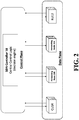
- FIG. 2 is a block diagram depicting components of a data plane and a control plane of a radio access network (RAN) according to an embodiment of the invention.
- the control plane includes an SDN controller 10, while the data plane includes a radio unit RU12, a centralized processing unit CU14, and forwarding nodes 16A and 16B.
- Forwarding nodes 16A and 16B can be, e.g., switches, routers, hubs, etc.
- FIG. 3 is a flow diagram depicting a method of configuring resources of a radio access network (RAN) according to an embodiment of the invention.
- the SDN controller 10 programs local control logic inside each data plane node, i.e. inside the radio unit RU12, the centralized processing unit CU14, and the forwarding nodes 16A and 16B.
- each of the data plane nodes monitors at least one portion of a link between the radio unit RU12 and the central processing unit CU14.
- the monitoring performed at 301 can include monitoring of network metrics such as available bandwidth and comparing delays with predefined threshold delay values.
- the monitoring at 301 can further include configuring, by the SDN controller, a source forwarding element and a target forwarding element as monitoring probes such that one or more probe packets for performing the measurement task are generated by the one or more monitoring probes-as described above.
- There are different network monitoring approaches in SDN e.g. generating dedicated probes in the network to perform end-to-end monitoring, or leveraging the idea of in-switch packet generation.
- one of the data plane nodes detects a change in a condition of another data plane node or the at least one portion of the link between the radio unit RU12 and the central processing unit CU14. The detection of a change in condition of a node or a link can be based on network measurements, e.g.
- RTT round-trip time
- OTD one-way delay
- jitter throughput
- available bandwidth available bandwidth
- one of the data plane nodes can detect a change in condition by determining that the available bandwidth falls below a certain threshold or delays of a traffic flow exceed certain thresholds.
- the data plane node that detected the change consults its local control logic and determines, at 303, whether any data plane nodes need to be reconfigured in response to the change detected at 302.
- the data plane node that detected the change at 302 can, at 303, (i) identify which data plane nodes, including the radio unit RU12 and the central processing unit CU14 as well as other radio units and central processing units, are affected by the change, (ii) determine which of the identified data plane nodes are to be reconfigured, e.g. in order to implement an updated RAN functional split, and (iii) select a particular RAN functional split for each of the data plane nodes that is to be reconfigured.
- the decisions at 302 are made pursuant to the local control logic inside the data plane node that detected the change at 302.
- the control logic inside the data plane nodes can be defined in a static table (as opposed to being programmed by the SDN controller 10 in 300).
- the local control logic according to which an RAN functional split is selected for each of the data plane nodes that is to be reconfigured can be based on a measured Modulation and Coding Scheme (MCS), on queue states inside a node, and/or on additional measurements of delays or available capacity.
- MCS Modulation and Coding Scheme
- the data plane node that has selected a particular RAN functional split for each of the data plane nodes that is to be reconfigured informs other data plane nodes of the determined needed reconfiguration and the selected RAN functional split and applies changes necessary to implement the determined reconfiguration as necessary.
- the data plane node that has selected a particular RAN functional split for each of the data plane nodes that is to be reconfigured informs the SDN controller 10 of the reconfiguration.
- an in-switch packet generation method can be utilized.
- Such packet generation method can include creating packet template information, including at least one of one or more packet templates or packet template handling instructions, providing the packet template information to one or more selected forwarding elements, the one or more selected forwarding elements being selected from the forwarding elements, triggering the one or more selected forwarding elements to generate an output packet based on the packet template information, and sending, by the selected forwarding elements, the generated output packet.
- the packet generation method is described in more detail in U.S. Patent Application Publication No. 2016/0134727 , which is incorporated by reference herein.
- FIG. 4 is a structural diagram depicting components of a radio access network (RAN) having a first functional configuration according to an embodiment of the invention.
- the RAN includes a small-cell network R1 connected to a network core vEPC via a backhaul network BH R1.
- the backhaul network BH R1 includes links between the network core vEPC and a data plane node 1, between the data plane node 1 and a data plane node 3, between the data plane node 3 and a data plane node 5, and between the data plane node 5 and the small-cell network R1.
- the RAN further includes two radio units R2 and R3 and a centralized processor unit CU.
- the centralized processor unit CU is connected to the network core vEPC via backhaul networks BH R2 and BH R3 and the radio units R2 and R3 are connected to the centralized processor unit CU via fronthaul networks FH R2 and FH R3.
- the fronthaul network FH R2 includes links from the centralized processor unit CU to a data plane node 2, from the data plane node 2 to a data plane node 6, and from the data plane node 6 to the radio unit R2.
- the fronthaul network FH R2 is configured for a specific functional split, i.e. split 4.
- the fronthaul network FH R3 includes links from the centralized processor unit CU to a data plane node 4, from the data plane node 4 to a data plane node 7, and from the data plane node 7 to the radio unit R3.
- the link between the node 4 and 7 is an mmWave link (E-band, at 70-80GHz).
- the fronthaul network FH R3 is configured for a specific functional split, i.e. split 4.
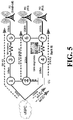
- FIG. 5 is a structural diagram depicting components of the radio access network (RAN) of FIG. 4 having a second functional configuration according to an embodiment of the invention.
- the link between the node 4 and 7 has degraded, e.g. due to weather changes, relative to its condition in FIG. 4 .
- the nodes 4 and 7 will automatically adapt the modulation and coding scheme (MCS) used on said link, e.g., using adaptive modulation radio (AMR).
- MCS modulation and coding scheme
- AMR adaptive modulation radio
- the nodes 4 and 7 determine that a reconfiguration of the fronthaul network FH R3 to split 3 is appropriate.
- the nodes 4 and 7 inform the radio unit R3 and the centralized processing unit CU of the reconfiguration, e.g. via in-switch packet generation methods (using PacketTemplates).
- the nodes that apply the changes necessary to implement the reconfiguration to split 3 inform a centralized SDN controller (not shown in the figures) of the changes.
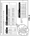
- FIG. 6 demonstrates a processing pipeline of a data plane node using OpenFlow according to an embodiment of the present invention.
- the processing pipeline consists of a flow table, a state table, and a packet template table.
- a local control logic is programmed inside the node, e.g. via a central SDN controller.
- Methods according to embodiments of the present invention include monitoring links between a radio unit and a central processing unit and detecting changes in network conditions. Once a degradation in a network metric below a preprogrammed acceptable level is detected, methods according to embodiments of the invention can mark all data traffic over the link at which the degradation was detected with a "link degraded" tag.
- embodiments of the invention can mark all data traffic over that link with a "link improved" tag.
- embodiments of the present invention can encode a current functional split (state column) per RU (key column) in the state table of the "functional split processing stage.”
- FIG. 6 includes the state of the small-cell R1 from FIG. 4 as being in state BH and includes the state of radio units R2 and R3 as being in state "split 4.”
- a first set of rules are utilized for regular forwarding of traffic.
- the first set of rules specifies actions to be taken that differ based on the current functional split.
- the rules may include executing a matching on the inner header fields of a certain functional split, which may or may not be used to decide the forwarding behavior.
- the inside headers of split 3 ⁇ 4 i.e. "hdr_Split_3/4," are optional to use to match to different forwarding actions.
- Each combination of split and RU can have multiple rules (e.g. up/downlink, different paths, load-balancing).
- a second set of rules is specified for cases in which a link quality degrades or improves. Such a change in link quality can cause an RAN functional split to change. For example, in FIG. 6 , when a current RAN functional split, i.e. "split 4," is matched with a "link degrade” marking in respective data traffic, the second set of rules specifies that two packets are to be generated: one according to template rule #40 and another according to template rule #41. Similarly, when a current RAN functional split, i.e. "split 4,” is matched with a "link improve" marking in respective data traffic, the second set of rules also specifies that two packets are to be generated: one according to template rule #45 and one according to template rule #46. In different embodiment, the rules can be pre-configured by the SDN controller or can be statically programmed into the data plane nodes.
- packet generation rules can be equipped with an inactivity timer that disables them for a predefined period of time.
- a higher (relative to the packet generation rules) priority rule to not generate packets with a timeout can be specified, thereby avoiding triggering the match that generates the "split change" packets. Once the timeout is reached this high priority rule is removed.
- the respective packet generation rule (via the ID number) in the packet template table can be used to assemble and send out a packet.
- packet generation rule #40 specifies the packet template "Change to Split 3" and copy instructions specify that a destination address in the template should be replaced with a destination address of the data packet triggering the packet generation.
- rule #41 in which the destination address in the template is replaced with the source address of the data packet triggering the packet generation, this results in both the RU and CU being notified of the need to change the functional split.
- the switches In order to remove unnecessary information from the packets, the switches should remove the degrade/improve marking before sending them out onto the network.
- FIG. 7 demonstrates an application of link quality change markings according to an embodiment of the present invention.
- FIG. 7 demonstrates how data packets are marked when link quality changes are detected. The process of marking data packets with link quality changes will happen in the same data plane node for which the processing pipeline of FIG. 6 is applicable but in a different processing stage, i.e. a "degrade/improve marking stage.”
- the state table encodes a current link quality level (state column) for all the links (key column) present in a network element.
- the current link quality (state) does not match the functional split requirements (e.g. insufficient capacity) as inferred from the data traffic for a specific link, the packets are marked.
- the quality level number matches the functional split indicator. If a link quality is below a required capacity of a particular functional split (e.g.
- the bottom of the flow table demonstrates how to update the link quality in the state table.
- the measurement and link quality level assignment might require more rules, depending on type of metric(s) used, e.g. a round-trip time measurement, a one-way delay measurement, a jitter measurement, a throughput measurement, and/or an available bandwidth measurement. This logic of what a functional split requires in terms of link quality will need to be programmed by the controller in advance.
- the recitation of "at least one of A, B and C” should be interpreted as one or more of a group of elements consisting of A, B and C, and should not be interpreted as requiring at least one of each of the listed elements A, B and C, regardless of whether A, B and C are related as categories or otherwise.
- the recitation of "A, B and/or C" or "at least one of A, B or C” should be interpreted as including any singular entity from the listed elements, e.g., A, any subset from the listed elements, e.g., A and B, or the entire list of elements A, B and C.
Landscapes
- Engineering & Computer Science (AREA)
- Computer Networks & Wireless Communication (AREA)
- Signal Processing (AREA)
- Quality & Reliability (AREA)
- Mobile Radio Communication Systems (AREA)
Abstract
Description
- The invention relates to mobile or wireless networks and mobile or wireless network architectures, and particularly to methods and systems for providing functional splits in radio access networks.
- 5G networks will allow for various degrees of Radio Access Network (RAN) centralization, varying from no centralization D-RAN (Distributed), to fully Centralized-RAN (C-RAN). In order to allow for such varying degrees of RAN centralization, 5G mobile transport networks will be required to support RAN functional splits in a flexible manner. Thereby, the division between fronthaul, which is the interface between a radio unit (RU) and an associated centralized-processing unit (CU), and backhaul, which is the interface connecting base stations and the mobile core, will blur since varying portions of functionality of the base stations will be distributed across the transport network. In this context, a new generation of transport network is proposed for 5G, namely crosshaul, integrating multi-technology fronthaul and backhaul segments into a common transport infrastructure.
- Centralizing base station (BS) functionality as much as a possible at a CU can have significant advantages in reducing operational costs by providing, e.g., common refrigeration, single-point maintenance, etc. Furthermore, centralization of base station functionality can achieve higher capacity gains by providing, e.g., joint signal processing, coordinated resource allocation, etc. However, transport requirements for the fronthaul, e.g. network capacity, delay, jitter, etc., are very tight and can become more stringent when more functions are centralized at a CU. For example, Table 1 below provides analysis of a functional split described in Small Cell Virtualization Functional Splits and Use Cases from Small Cell Forum, Release 6.0 Version 159.06.02 issued on January 13, 2016.
-
Table 1: Functional splits analysis: 1 user/TTI, 20 MHz BW, IP MTU 1500B; DL: MCS, 2x2 MIMO, 100RBs, 2 TBs of 75376 bits/subframe, CFI=1; MCS 23, 1x2 SIMO, 96 RBs, 1 TB of 48936 bits/subframe Split # BS Functional Decomposition DL/UL BW Requirement (Mb/s) Delay Requireme nt (µs) Gains A RRC-PDCP 151/48 30,000 • Enables L3 functionality for multiple small cells to use the same HW • Enhanced mobility across nodes w/o inter-small cell data forwarding/signalling • Reduced mobility-related signalling to the mobile core segment • No X2 endpoints between small cells and macro eNBs • Control plane and user plane separation B PDCP-RLC 151/48 30,000 • Enables L3 and some L2 functionality to use the same HW C RLC-MAC 151/48 6000 • Resource sharing benefits for both storage and processor utilization D Split MAC 151/49 6000 • Synchronized coordination and control of multiple cells • Coordination across cells enables CA, CoMP, eICIC or cross carrier scheduling E MAC-PHY 152/49 250 • Enhancements to CoMP with RU frame alignment and centralized HARQ F PHY Split I 173/452 250 • More opportunities to disable parts of the CU at quiet times to save power G PHY Split II 933/903 250 • Central L1 CU can be scaled based on average utilization across all cells H PHY Split III 1075/922 250 • Smaller CU results in less processing resource and power saving I PHY Split IIIb 1966/1966 250 • Enhancements to joint reception CoMP with uplink PHY level combining J PHY Split IV 2457.6/ 2457.6 250 - A centralized software defined network (SDN) control approach for integrated fronthaul and backhaul network resource management is described in
PCT/EP 2016/057357 - In an embodiment, the present invention provides a method for configuring resources of a radio access network (RAN) including a radio unit. The method includes monitoring, by a data plane node, a quality of at least one portion of a link between the radio unit and a central processing unit of the RAN; determining, by the data plane node, that the quality of the at least one portion of the link has changed relative to a previous quality of the at least one portion of the link; generating, by the data plane node according to local control logic programmed into the data plane node, a decision specifying a placement for one or more RAN functions; and transmitting, by the data plane node to one or both of the radio unit and the central processing unit, a notification including the decision specifying the placement for the one or more RAN functions.
- The present invention will be described in even greater detail below based on the exemplary figures. The invention is not limited to the exemplary embodiments. All features described and/or illustrated herein can be used alone or combined in different combinations in embodiments of the invention. The features and advantages of various embodiments of the present invention will become apparent by reading the following detailed description with reference to the attached drawings which illustrate the following:
-
FIG. 1 depicts a radio access network (RAN) having an integrated fronthaul and backhaul network, i.e. a crosshaul network, according to an embodiment of the invention; -
FIG. 2 is a block diagram depicting components of a data plane and a control plane of a radio access network (RAN) according to an embodiment of the invention; -
FIG. 3 is a flow diagram depicting a method of configuring resources of a radio access network (RAN) according to an embodiment of the invention; -
FIG. 4 is a structural diagram depicting components of a radio access network (RAN) having a first functional configuration according to an embodiment of the invention; -
FIG. 5 is a structural diagram depicting components of the radio access network (RAN) ofFIG. 4 having a second functional configuration according to an embodiment of the invention; -
FIG. 6 demonstrates a processing pipeline of a data plane node using OpenFlow according to an embodiment of the present invention; and -
FIG. 7 demonstrates an application of link quality change markings according to an embodiment of the present invention. - Supporting flexible RAN functional splits while meeting their most stringent requirements is one of the main challenges of providing a crosshaul transport network. To support dynamic RAN functional splits, support for a number of different capabilities is required. Reacting quickly to network/load changes requires support for dynamic functional split changes in a timely and efficient manner. Reacting quickly to network/load changes requires rapid detection of critical network/load changes and rapid reporting of said changes to related network elements. Therefore, network monitoring and quick detection of any critical network changes is a crucial task for a resilient crosshaul transport network. Furthermore, dynamic RAN functional splits must ensure that the stringent transport requirements of fronthaul traffic are met. This requires continuous network monitoring to allow for adaptive re-configuration.
- In a centralized SDN control system, unpredictable delays may occur in the control plane. Such delays can be caused by latency between a controller and switches (such latency can vary depending on a load of the control network and the individual switches) and latency inside an SDN switch between an SDN agent and the forwarding pipeline. Furthermore, delays can be caused by overload in the control network (which can also be referred to as the control channel, e.g. in OpenFlow) or in the SDN controller. Delays can also be caused by control channel failures, which will prevent the network from functioning as desired. These delays in the control plane can delay or prevent data plane nodes from reacting to network changes. Timely network adaptations (as required for RAN functional split changes) rely on the ability of data plane nodes to rapidly and reliably react to network changes. Therefore, implementation of RAN functional split changes can be problematic when delays in the control plane cause data plane nodes to react to network changes in a delayed manner or prevent data plane nodes from reacting to network changes altogether-as can occur in large networks with a high number of nodes and links where the control channels may not be ideal.
- Methods according to embodiments of the invention provide for dynamic RAN functional splits to adapt to actual network/load changes (e.g. wireless link changes) in a fast and timely manner. According to such methods, RAN functional split decision-making can be offloaded, at least in part, from a central SDN controller to distributed data plane nodes in order to improve RAN resiliency and reaction speed. In this manner, RAN functional split decision-making is distributed, at least in part, to data plane nodes. Such data plane nodes, e.g. switches, routers, etc., can be remotely located from one another and wirelessly connected to one another. According to embodiments of the invention, an approach for offloading RAN functional split decision-making to data plane nodes can leverage stateful flow processing and in-switch packet generation mechanisms. Such an approach can consider a complete network or path between an RU and a CU.
- According to embodiments of the invention, the approach of distributing RAN functional split decision-making to data plane nodes can be used to complement a centralized SDN control approach to enable dynamic RAN functional split changes thereby resulting in a hierarchical RAN functional split decision-making process. In some such embodiments, decisions regarding RAN functional splits are made centrally by an SDN controller when, e.g., the control channels are ideal without severe delays and losses and the decisions regarding RAN functional splits are made in a distributed manner at local data plane nodes when control channel conditions are, e.g., non-ideal. In order to keep an updated control plane, the data plane nodes will inform the centralized SDN controller of local decisions regarding RAN functional splits. For example, in-switch packet generation and stateful flow processing can be leveraged to propagate distributed decisions through a data plane towards an RU and a CU.
- The distribution of RAN functional split decision-making, at least in part, to data plane nodes can address problems in the control plane (e.g. excessive delays, losses, overload, or even failures) that can prevent data plane nodes from quickly reacting to network changes. Therefore, by distributing RAN functional split decision-making, at least in part, to data plane nodes, embodiments of the present invention can address certain problems of a centralized SDN control approach.
- Embodiments of the present invention can utilize a software defined network (SDN) or network function virtualization (NFV) based architecture to enable a flexible and software-defined reconfiguration of networking elements through a unified data plane and control plane interconnecting distributed 5G radio access and core network functions. Such SDN/NFV based architecture can be hosted on in-network cloud infrastructure. Furthermore, such SDN/NFV based architecture follows the principles of SDN architecture proposed by the Open Networking Foundation (ONF) by decoupling the data and control planes.
- Embodiments of the present invention provide methods for configuring resources of a radio access network (RAN) including a radio unit. Such methods can include monitoring, by a data plane node, a quality of at least one portion of a link between the radio unit and a central processing unit of the RAN; determining, by the data plane node, that the quality of the at least one portion of the link has changed relative to a previous quality of the at least one portion of the link; generating, by the data plane node according to local control logic programmed into the data plane node, a decision specifying a placement for one or more RAN functions; and transmitting, by the data plane node to one or both of the radio unit and the central processing unit, a notification including the decision specifying the placement for the one or more RAN functions. Methods can also include receiving, by the data plane node, programming from a software defined network (SDN) controller by which the local control logic is programmed into the data plane node. Furthermore, methods can additionally include transmitting, by the data plane node to the SDN controller, a notification including the decision specifying the placement for the one or more RAN functions.
- In one or more embodiments, methods can include, as a component of the decision specifying the placement for one or more RAN functions, specifying a RAN functional split from a group of RAN functional splits. Methods can further include forwarding, by the data plane node, traffic between the radio unit and the central processing unit according to a set of rules determined according to the specified RAN functional split. Each RAN functional split of the group of RAN functional splits can specify a location from a plurality of locations at which each of a plurality of baseband processing functions is to be performed. The locations at which the baseband processing functions are to be performed include the radio unit and the central processing unit. The plurality of baseband processing functions can include physical layer functions, data link layer functions, and network layer functions. More specifically, the baseband processing functions can include implementation of protocols including physical layer protocols, media access control (MAC) protocols, radio link control (RLC) protocol, packet data convergence protocol (PDCP), and radio resource control (RRC) protocol.
- In one or more embodiments, monitoring the quality of the at least one portion of the link between the radio unit and the central processing unit can include configuring, by the SDN controller, a source forwarding element and a target forwarding element as monitoring probes such that one or more probe packets for performing the measurement task are generated by the one or more monitoring probes. The source forwarding element and the target forwarding element can be, e.g. switches or routers along the path from the radio unit to the central processing unit. The term "monitoring probe" can refer to a program executed by one or more of the source forwarding element and the target forwarding element. The one or more probe packets can include a ping probe packet generated by the source forwarding element for performing a measurement task and a pong probe packet generated by the target forwarding element. The SDN controller can configure the monitoring probes to generate one or more probe packets by creating probe packet template information that is provided to the monitoring probes, wherein the probe packet template information includes one or more probe packet templates and/or probe packet template handling instructions. The monitoring probes can thereby be triggered to generate the one or more probe packets based on the provided packet template information. Triggering instructions may be provided to the monitoring probes by including them into the packet template information. Such triggering instructions may include configuring a timer as a trigger for generating the one or more probe packets. For example, the triggering instructions may include configuring a timer at the source forwarding element, wherein the timer triggers the generation of one or more ping probe packets that are sent to the target forwarding element. Furthermore, the triggering instructions may include configuring a reception of a predetermined probe packet as a trigger for generating a new probe packet, in particular a pong probe packet.
- Monitoring the quality of the at least one portion of the link between the radio unit and the central processing unit can further include taking one or more measurements. The one or more measurements can be based on time-stamping performed by at least one of the monitoring probes. Time stamps can be recorded and/or added to probe packets directly on and by the forwarding elements and can be based on a time provided by an internal clock of at least one of the forwarding elements. The taking one or more measurements can include taking a round-trip time measurement, a one-way delay measurement, a jitter measurement, a throughput measurement, and/or an available bandwidth measurement. The result of the taking of one or more measurements, i.e. a measurement result, can be computed after collecting measurement feedback, wherein the measurement feedback is based on returned probe packets, in particular, returned pong probe packets. The measurement result may be computed by the SDN controller and/or by a dedicated measurement analysis component. The measurement feedback can include probe packets that are sent back to the SDN, wherein the probe packets may comprise collected information such as time stamps, statistic counters, etc.
- Generally, network monitoring and/or network measurement may be performed on multi-hop paths through the network, due to the way that monitoring probes are deployed on the edge of the network, or at selected locations within the network. Yet with an SDN controlled measurement system all the above measurement techniques-i.e. round-trip time measurement, one-way delay measurement, jitter measurement, throughput measurement, and/or an available bandwidth estimation-which support multi-hop measurement can also be run on shorter paths and even individual links. Thus, with the option to perform accurate timed measurements while being able to generate the probe packets at each forwarding element in the network, once an SLA violation (i.e. a fault or degradation of performance) is detected on a multi-hop path, the software defined network controller can issue additional measurements on a sub-path until the source of the problem is identified. Thus, pinpointing sources of SLA violations can be provided.
- In one or more embodiments, determining that the quality of the at least one portion of the link has changed relative to a previous quality of the at least one portion of the link can include comparing a measurement result on a portion of a link from a first, earlier point in time with a measurement result on the same portion of the link from a second, latter point in time. Determining that the quality of the portion of the link has changed may include determining that the difference between a measurement result, e.g. the result of a round-trip time measurement, a one-way delay measurement, a jitter measurement, a throughput measurement, and/or an available bandwidth measurement, from a first, earlier point in time and a corresponding measurement result from a second latter point in time exceeds a threshold.
- Embodiments of the present invention provide systems for dynamic RAN functional splits that rapidly adapt to actual network/load changes (e.g. wireless link changes). Such systems can include an SDN controller, one or more data plane nodes (which can be, e.g., routers, switches, and hubs), an RU, and a CU. The SDN controller can configure a source forwarding element and a target forwarding element as monitoring probes such that one or more probe packets for performing the measurement task are generated by the one or more monitoring probes-as described above. Furthermore, the SDN controller can also be configured to program local control logic inside each of the one or more data plane nodes.
- In embodiments of the present invention utilizing a hierarchical RAN functional split decision-making process in which a centralized SDN control approach is complemented with a distributed decision approach, an RAN functional split decision made by a centralized SDN controller can conflict with an RAN functional split decision made locally by a data plane node. According to various embodiments of the invention, such conflicts can be resolved by a timer-based approach or by a command-based approach. For example, the SDN controller can coordinate with the data plane nodes by sending control messages commanding them to take over RAN functional split decision-making locally for a predefined period of time or by sending control messages requesting that they return RAN-functional split decision-making roles to the SDN controller. Alternatively, timers at the data plane nodes can be utilized. For example, a data plane node can start a timer upon detecting a need for a change of an RAN functional split, and if the data plane node does not receive a decision from the central controller regarding an updated RAN functional split before the timer expires, then the data plane node applies a local decision regarding an updated RAN functional split. A timer can also be used to determine a period of time for which the local decision remains effective before a decision from the SDN controller becomes effective.
- Similarly, an RAN functional split decision made locally by a first data plane node can conflict with an RAN functional split decision made locally by a second data plane node. Such conflicts may arise when several distributed nodes along a path from an RU to a CU independently detect changes in the network and independently make decisions regarding an RAN functional split that should be implemented in response to the detected changes. In some cases, the independent decisions regarding the functional split that should be implemented may conflict with one another. In such instances, a mechanism for resolving such conflicts is necessary. According to various embodiments of the present invention, data plane nodes that make conflicting decisions regarding a functional split that should be implemented in response to detected network changes select the functional split has the lowest requirements for the fronthaul network. In some implementations, conflicts originating from data plane nodes regarding a functional split that should be implemented in response to detected network changes are resolved by one or both of a CU and an RU.
- In case of path failure which may require a new path between the RU and the CU, the RU can try to use a backup/protection path (assuming already pre-computed during the planning phase). Once the link is down, the RU can change to the backup path. Then the first node on the backup path can apply the same local control logic inside the node to decide the proper functional split for that RU. Alternatively, the network can resort to the centralized SDN approach (if there is central controller in the system) to make a global optimized decision on the routing and functional splits for all RUs connecting to their associated CU.
-
FIG. 1 depicts a radio access network (RAN) having an integrated fronthaul and backhaul network, i.e. a crosshaul network, according to an embodiment of the invention. The RAN network depicted inFIG. 1 includes a plurality of radio units RU1 through RU6, centralized processing units CU1 and CU2, and a number of data plane nodes DN. Links between data plane nodes DN are designated as being a component of either a fronthaul network (FH), i.e. part of the interface between one of radio units RU1 through RU6 and one of centralized processing units CU1 and CU2, or a combination of a fronthaul network and a backhaul network (FH+BH), i.e. part of the interface between centralized processing unit CU1 and the core network (i.e. Core EPC) and also part of the interface between one of radio units RU1 through RU6 and one of centralized processing units CU1 and CU2.FIG. 1 additionally depicts a plurality of base stations BS1 through BS6, each of which corresponds to one of radio units RU1 through RU6 respectively. The functionality of each of base stations BS1 through BS3 is distributed between a combination of one of radio units RU1 through RU3 and the centralized processing unit CU1. Similarly, the functionality of each of the base stations BS4 through BS6 is distributed between a combination of one of radio units RU4 through RU6 and the centralized processing unit CU2. -
FIG. 2 is a block diagram depicting components of a data plane and a control plane of a radio access network (RAN) according to an embodiment of the invention. The control plane includes anSDN controller 10, while the data plane includes a radio unit RU12, a centralized processing unit CU14, and forwardingnodes Forwarding nodes -
FIG. 3 is a flow diagram depicting a method of configuring resources of a radio access network (RAN) according to an embodiment of the invention. At 300, theSDN controller 10 programs local control logic inside each data plane node, i.e. inside the radio unit RU12, the centralized processing unit CU14, and theforwarding nodes - Once a change in condition has been detected at 302, the data plane node that detected the change consults its local control logic and determines, at 303, whether any data plane nodes need to be reconfigured in response to the change detected at 302. For example, the data plane node that detected the change at 302 can, at 303, (i) identify which data plane nodes, including the radio unit RU12 and the central processing unit CU14 as well as other radio units and central processing units, are affected by the change, (ii) determine which of the identified data plane nodes are to be reconfigured, e.g. in order to implement an updated RAN functional split, and (iii) select a particular RAN functional split for each of the data plane nodes that is to be reconfigured. The decisions at 302 are made pursuant to the local control logic inside the data plane node that detected the change at 302. In alternative embodiments, the control logic inside the data plane nodes can be defined in a static table (as opposed to being programmed by the
SDN controller 10 in 300). The local control logic according to which an RAN functional split is selected for each of the data plane nodes that is to be reconfigured can be based on a measured Modulation and Coding Scheme (MCS), on queue states inside a node, and/or on additional measurements of delays or available capacity. - At 304, the data plane node that has selected a particular RAN functional split for each of the data plane nodes that is to be reconfigured informs other data plane nodes of the determined needed reconfiguration and the selected RAN functional split and applies changes necessary to implement the determined reconfiguration as necessary. At 305, the data plane node that has selected a particular RAN functional split for each of the data plane nodes that is to be reconfigured informs the
SDN controller 10 of the reconfiguration. In order to propagate the reconfiguration decisions across the data plane, an in-switch packet generation method can be utilized. Such packet generation method can include creating packet template information, including at least one of one or more packet templates or packet template handling instructions, providing the packet template information to one or more selected forwarding elements, the one or more selected forwarding elements being selected from the forwarding elements, triggering the one or more selected forwarding elements to generate an output packet based on the packet template information, and sending, by the selected forwarding elements, the generated output packet. The packet generation method is described in more detail inU.S. Patent Application Publication No. 2016/0134727 , which is incorporated by reference herein. -
FIG. 4 is a structural diagram depicting components of a radio access network (RAN) having a first functional configuration according to an embodiment of the invention. InFIG. 4 , the RAN includes a small-cell network R1 connected to a network core vEPC via a backhaul network BH R1. The backhaul network BH R1 includes links between the network core vEPC and adata plane node 1, between thedata plane node 1 and adata plane node 3, between thedata plane node 3 and adata plane node 5, and between thedata plane node 5 and the small-cell network R1. The RAN further includes two radio units R2 and R3 and a centralized processor unit CU. The centralized processor unit CU is connected to the network core vEPC via backhaul networks BH R2 and BH R3 and the radio units R2 and R3 are connected to the centralized processor unit CU via fronthaul networks FH R2 and FH R3. The fronthaul network FH R2 includes links from the centralized processor unit CU to adata plane node 2, from thedata plane node 2 to adata plane node 6, and from thedata plane node 6 to the radio unit R2. InFIG. 4 , the fronthaul network FH R2 is configured for a specific functional split, i.e.split 4. Similarly, the fronthaul network FH R3 includes links from the centralized processor unit CU to adata plane node 4, from thedata plane node 4 to adata plane node 7, and from thedata plane node 7 to the radio unit R3. The link between thenode FIG. 4 , the fronthaul network FH R3 is configured for a specific functional split, i.e.split 4. -
FIG. 5 is a structural diagram depicting components of the radio access network (RAN) ofFIG. 4 having a second functional configuration according to an embodiment of the invention. InFIG. 5 , the link between thenode FIG. 4 . In response to detected the degradation of the link between them, thenodes nodes FIG. 5 , thenodes nodes -
FIG. 6 demonstrates a processing pipeline of a data plane node using OpenFlow according to an embodiment of the present invention. The processing pipeline consists of a flow table, a state table, and a packet template table. In addition, a local control logic is programmed inside the node, e.g. via a central SDN controller. Methods according to embodiments of the present invention include monitoring links between a radio unit and a central processing unit and detecting changes in network conditions. Once a degradation in a network metric below a preprogrammed acceptable level is detected, methods according to embodiments of the invention can mark all data traffic over the link at which the degradation was detected with a "link degraded" tag. Similarly, when a metric of the link improves above a certain level, methods according to embodiments of the invention can mark all data traffic over that link with a "link improved" tag. For notifying RUs and CUs of a required change in an RAN functional split, embodiments of the present invention can encode a current functional split (state column) per RU (key column) in the state table of the "functional split processing stage." For example,FIG. 6 includes the state of the small-cell R1 fromFIG. 4 as being in state BH and includes the state of radio units R2 and R3 as being in state "split 4." - In the next step in the processing pipeline (cf. flow table), a first set of rules are utilized for regular forwarding of traffic. The first set of rules specifies actions to be taken that differ based on the current functional split. The rules may include executing a matching on the inner header fields of a certain functional split, which may or may not be used to decide the forwarding behavior. In
FIG. 6 , the inside headers of split ¾, i.e. "hdr_Split_3/4," are optional to use to match to different forwarding actions. Each combination of split and RU can have multiple rules (e.g. up/downlink, different paths, load-balancing). - A second set of rules is specified for cases in which a link quality degrades or improves. Such a change in link quality can cause an RAN functional split to change. For example, in
FIG. 6 , when a current RAN functional split, i.e. "split 4," is matched with a "link degrade" marking in respective data traffic, the second set of rules specifies that two packets are to be generated: one according totemplate rule # 40 and another according totemplate rule # 41. Similarly, when a current RAN functional split, i.e. "split 4," is matched with a "link improve" marking in respective data traffic, the second set of rules also specifies that two packets are to be generated: one according totemplate rule # 45 and one according totemplate rule # 46. In different embodiment, the rules can be pre-configured by the SDN controller or can be statically programmed into the data plane nodes. - In order to avoid flooding of split change messages, packet generation rules can be equipped with an inactivity timer that disables them for a predefined period of time. Alternatively a higher (relative to the packet generation rules) priority rule to not generate packets with a timeout can be specified, thereby avoiding triggering the match that generates the "split change" packets. Once the timeout is reached this high priority rule is removed.
- When the action in the flow table prescribes a packet generation, the respective packet generation rule (via the ID number) in the packet template table can be used to assemble and send out a packet. For example, in
FIG. 6 packetgeneration rule # 40 specifies the packet template "Change toSplit 3" and copy instructions specify that a destination address in the template should be replaced with a destination address of the data packet triggering the packet generation. Together withrule # 41, in which the destination address in the template is replaced with the source address of the data packet triggering the packet generation, this results in both the RU and CU being notified of the need to change the functional split. - In order to remove unnecessary information from the packets, the switches should remove the degrade/improve marking before sending them out onto the network.
-
FIG. 7 demonstrates an application of link quality change markings according to an embodiment of the present invention.FIG. 7 demonstrates how data packets are marked when link quality changes are detected. The process of marking data packets with link quality changes will happen in the same data plane node for which the processing pipeline ofFIG. 6 is applicable but in a different processing stage, i.e. a "degrade/improve marking stage." - In
FIG. 7 , the state table encodes a current link quality level (state column) for all the links (key column) present in a network element. In the flow table, if the current link quality (state) does not match the functional split requirements (e.g. insufficient capacity) as inferred from the data traffic for a specific link, the packets are marked. In the example depicted inFIG. 7 , the quality level number matches the functional split indicator. If a link quality is below a required capacity of a particular functional split (e.g. "Lvl 3" is below the capacity requirement of "Split 4") packets should be marked with "degrade." On the other hand, if a link quality is above a required capacity of a particular functional split, packets can be marked with "improve." A current split option can be matched in headers of the data stream. Traffic marking can also be performed in unused header fields. Which exact fields are unused depends on specific deployment requirements, but the SDN controller/administrator can identify an appropriate field. - The bottom of the flow table demonstrates how to update the link quality in the state table. The measurement and link quality level assignment might require more rules, depending on type of metric(s) used, e.g. a round-trip time measurement, a one-way delay measurement, a jitter measurement, a throughput measurement, and/or an available bandwidth measurement. This logic of what a functional split requires in terms of link quality will need to be programmed by the controller in advance.
- While the invention has been illustrated and described in detail in the drawings and foregoing description, such illustration and description are to be considered illustrative or exemplary and not restrictive. It will be understood that changes and modifications may be made by those of ordinary skill within the scope of the following claims. In particular, the present invention covers further embodiments with any combination of features from different embodiments described above and below.
- The terms used in the claims should be construed to have the broadest reasonable interpretation consistent with the foregoing description. For example, the use of the article "a" or "the" in introducing an element should not be interpreted as being exclusive of a plurality of elements. Likewise, the recitation of "or" should be interpreted as being inclusive, such that the recitation of "A or B" is not exclusive of "A and B," unless it is clear from the context or the foregoing description that only one of A and B is intended. Further, the recitation of "at least one of A, B and C" should be interpreted as one or more of a group of elements consisting of A, B and C, and should not be interpreted as requiring at least one of each of the listed elements A, B and C, regardless of whether A, B and C are related as categories or otherwise. Moreover, the recitation of "A, B and/or C" or "at least one of A, B or C" should be interpreted as including any singular entity from the listed elements, e.g., A, any subset from the listed elements, e.g., A and B, or the entire list of elements A, B and C.
Claims (15)
- A method for configuring resources of a radio access network, RAN, including a radio unit, the method comprising:monitoring, by a data plane node, a quality of at least one portion of a link between the radio unit and a central processing unit of the RAN;determining, by the data plane node, that the quality of the at least one portion of the link has changed relative to a previous quality of the at least one portion of the link;generating, by the data plane node according to local control logic programmed into the data plane node, a decision specifying a placement for one or more RAN functions; andtransmitting, by the data plane node to one or both of the radio unit and the central processing unit, a notification including the decision specifying the placement for the one or more RAN functions.
- The method of claim 1, further comprising receiving, by the data plane node, programming from a software defined network, SDN, controller by which the local control logic is programmed into the data plane node.
- The method of claim 2, further comprising transmitting, by the data plane node to the SDN controller, a notification including the decision specifying the placement for the one or more RAN functions.
- The method according to one of claims 1 to 3, wherein the monitoring the quality of the at least one portion of the link between the radio unit and the central processing unit comprises taking one or more of a round-trip time measurement, a one-way delay measurement, a jitter measurement, a throughput measurement, and an available bandwidth measurement.
- The method according to one of claims 1 to 4, wherein the determining that the quality of the at least one portion of the link has changed relative to a previous quality of the at least one portion of the link comprises determining that one or more of a round-trip time measurement, a one-way delay measurement, a jitter measurement, a throughput measurement, and an available bandwidth measurement taken at a first point in time differs by a threshold amount from a corresponding round-trip time measurement, a one-way delay measurement, a jitter measurement, a throughput measurement, and/or an available bandwidth measurement taken at a second point in time.
- The method according to one of claims 1 to 5, wherein the decision specifying the placement for one or more RAN functions comprises specifying a RAN functional split from a group of RAN functional splits.
- The method of claim 6, further comprising forwarding, by the data plane node, traffic between the radio unit and the central processing unit according to a set of rules determined according to the specified RAN functional split.
- The method of claim 6 or 7, wherein RAN functional split of the group of RAN functional splits specifies a location from a plurality of locations at which each of a plurality of baseband processing functions is to be performed.
- The method of claim 8, wherein the plurality of locations comprises the radio unit and the central processing unit.
- The method according to one of claims 1 to 9, further comprising starting, in response to the generating the decision specifying the placement for one or more RAN functions, a timer that determines a time interval during with the specified placement for the one or more RAN functions will remain effective.
- The method of claim 10, wherein at the end of the time interval, the method further comprises:determining a default set of rules for specifying a placement for one or more RAN functions, wherein the default set of rules is determined by the SDN controller; andforwarding, by the data plane node, traffic between the radio unit and the central processing unit according to a set of rules determined according to the specified RAN functional split.
- The method according to one of claims 1 to 11, wherein the generating a decision specifying a placement for one or more RAN functions is triggered by the determining that the quality of the at least one portion of the link has changed relative to a previous quality of the at least one portion of the link.
- The method according to one of claims 1 to 12, wherein the one or more RAN functions include one or more of physical layer functions, data link layer functions, and network layer functions.
- A radio access network, RAN, data plane node, preferably for performing the method according to one of claims 1 to 13, comprising:a processor; anda non-transitory processor readable medium having stored thereon processor executable instructions for:monitoring a quality of at least one portion of a link between the radio unit and the central processing unit,determining that the quality of the at least one portion of the link has changed relative to a previous quality of the at least one portion of the link,generating, according to local control logic programmed into the data plane node, a decision specifying a placement for one or more RAN functions; andtransmitting, to one or both of the radio unit and the central processing unit, a notification including the decision specifying the placement for the one or more RAN functions.
- A system for configuring resources of a radio access network, RAN, including a radio unit, preferably for performing the method according to one of claims 1 to 13, the system comprising:a data plane node, comprising a processor and a non-transitory processor readable medium having stored thereon processor executable instructions for:monitoring a quality of at least one portion of a link between the radio unit and the central processing unit,determining that the quality of the at least one portion of the link has changed relative to a previous quality of the at least one portion of the link,generating a decision specifying a placement for one or more RAN functions, andtransmitting, to one or both of the radio unit and a central processor of the RAN, a notification including the decision specifying the placement for the one or more RAN functions; andthe central processor of the RAN.
Applications Claiming Priority (1)
| Application Number | Priority Date | Filing Date | Title |
|---|---|---|---|
| US15/788,880 US10531351B2 (en) | 2017-10-20 | 2017-10-20 | Method for in-network, dynamic radio access network functional split configuration by radio access network data plane forwarding nodes |
Publications (2)
| Publication Number | Publication Date |
|---|---|
| EP3474519A1 true EP3474519A1 (en) | 2019-04-24 |
| EP3474519B1 EP3474519B1 (en) | 2020-08-19 |
Family
ID=63965256
Family Applications (1)
| Application Number | Title | Priority Date | Filing Date |
|---|---|---|---|
| EP18201775.6A Active EP3474519B1 (en) | 2017-10-20 | 2018-10-22 | Method for in-network dynamic radio access network functional split change utilizing software defined networking with in-switch packet generation and stateful flow processing |
Country Status (2)
| Country | Link |
|---|---|
| US (1) | US10531351B2 (en) |
| EP (1) | EP3474519B1 (en) |
Cited By (2)
| Publication number | Priority date | Publication date | Assignee | Title |
|---|---|---|---|---|
| CN111917653A (en) * | 2020-07-21 | 2020-11-10 | 广东省华南技术转移中心有限公司 | Data forwarding rule synchronization method, controller and system for SDN (software defined network) |
| WO2021155352A1 (en) * | 2020-01-31 | 2021-08-05 | Qualcomm Incorporated | Methods and apparatus for flexible configuration of fronthaul split radio units |
Families Citing this family (18)
| Publication number | Priority date | Publication date | Assignee | Title |
|---|---|---|---|---|
| EP3269118B8 (en) | 2015-03-11 | 2021-03-17 | CommScope, Inc. of North Carolina | Distributed radio access network with adaptive fronthaul |
| US10608734B2 (en) | 2015-10-22 | 2020-03-31 | Phluido, Inc. | Virtualization and orchestration of a radio access network |
| WO2018017468A1 (en) | 2016-07-18 | 2018-01-25 | Phluido, Inc. | Synchronization of radio units in radio access networks |
| WO2019127068A1 (en) | 2017-12-27 | 2019-07-04 | Intel Corporation | User plane apparatus for edge computing |
| US12016084B2 (en) * | 2018-01-04 | 2024-06-18 | Commscope Technologies Llc | Management of a split physical layer in a radio area network |
| US10832370B2 (en) | 2018-03-27 | 2020-11-10 | Arista Networks, Inc. | System and method of hitless reconfiguration of a data processing pipeline with standby pipeline |
| US10585725B2 (en) * | 2018-03-27 | 2020-03-10 | Arista Networks, Inc. | System and method of hitless reconfiguration of a data processing pipeline |
| BR112021004878A2 (en) * | 2018-09-21 | 2021-06-01 | British Telecommunications Public Limited Company | cellular telecommunications network |
| EP3888259A1 (en) * | 2018-11-30 | 2021-10-06 | Telefonaktiebolaget LM Ericsson (publ) | Methods for providing lower-layer split full spatial samples |
| EP3748562A1 (en) | 2019-05-08 | 2020-12-09 | EXFO Solutions SAS | Timeline visualization & investigation systems and methods for time lasting events |
| US10834618B1 (en) * | 2019-08-05 | 2020-11-10 | Sprint Communications Company L.P. | Wireless communication network access using different functionality splits for different communication services |
| KR20230031227A (en) | 2020-06-30 | 2023-03-07 | 콤스코프 테크놀로지스, 엘엘씨 | An open radio access network with an integrated remote unit supporting multiple functional divisions, multiple air interface protocols, multiple generations of radio access technologies and multiple radio frequency bands. |
| WO2022239295A1 (en) * | 2021-05-10 | 2022-11-17 | ソニーグループ株式会社 | Control device and control method, and device and processing method |
| US11836480B2 (en) | 2022-03-25 | 2023-12-05 | Dish Wireless L.L.C. | Systems and methods for reducing service downtime during software upgrades |
| US11877163B2 (en) * | 2022-03-25 | 2024-01-16 | Dish Wireless L.L.C. | Systems and methods for operating radio access networks with high service availability |
| CN114585101B (en) * | 2022-04-26 | 2022-10-28 | 阿里巴巴(中国)有限公司 | Network function division method, radio access network, device and storage medium |
| US12323298B2 (en) * | 2023-03-21 | 2025-06-03 | Dish Wireless L.L.C. | Open radio access network (ORAN) distributed unit with mutliple centralized units |
| US20260039535A1 (en) * | 2024-07-31 | 2026-02-05 | Cisco Technology, Inc. | Optimized network probing agent deployment and test scheduling |
Citations (2)
| Publication number | Priority date | Publication date | Assignee | Title |
|---|---|---|---|---|
| US20140092736A1 (en) * | 2012-10-02 | 2014-04-03 | Telefonaktiebolaget L M Ericsson (Publ) | Method and system for radio service optimization using active probing over transport networks |
| US20160134727A1 (en) | 2013-07-03 | 2016-05-12 | Nec Europe Ltd. | A method for operating a software defined network and a software defined network |
Family Cites Families (9)
| Publication number | Priority date | Publication date | Assignee | Title |
|---|---|---|---|---|
| US7441022B1 (en) * | 2004-03-12 | 2008-10-21 | Sun Microsystems, Inc. | Resolving conflicts between network service rule sets for network data traffic in a system where rule patterns with longer prefixes match before rule patterns with shorter prefixes |
| US9642146B2 (en) * | 2013-06-05 | 2017-05-02 | Huawei Technologies Co., Ltd. | System and method for an agile wireless access network |
| EP3001620A4 (en) * | 2013-06-25 | 2016-07-13 | Huawei Tech Co Ltd | ROUTING NODE, CONTROL NODE, AND PROCESSING METHOD FOR ROUTING NODE |
| CN104601526B (en) * | 2013-10-31 | 2018-01-09 | 华为技术有限公司 | A kind of method, apparatus of collision detection and solution |
| EP3269118B8 (en) * | 2015-03-11 | 2021-03-17 | CommScope, Inc. of North Carolina | Distributed radio access network with adaptive fronthaul |
| US10979319B2 (en) | 2016-04-04 | 2021-04-13 | Nec Corporation | Method for providing operating information for a network |
| US10149193B2 (en) * | 2016-06-15 | 2018-12-04 | At&T Intellectual Property I, L.P. | Method and apparatus for dynamically managing network resources |
| US9949133B2 (en) * | 2016-08-05 | 2018-04-17 | Nxgen Partners Ip, Llc | Ultra-broadband virtualized telecom and internet |
| WO2018077435A1 (en) | 2016-10-28 | 2018-05-03 | NEC Laboratories Europe GmbH | Method for supporting network monitoring in a software defined network and corresponding software defined network |
-
2017
- 2017-10-20 US US15/788,880 patent/US10531351B2/en active Active
-
2018
- 2018-10-22 EP EP18201775.6A patent/EP3474519B1/en active Active
Patent Citations (2)
| Publication number | Priority date | Publication date | Assignee | Title |
|---|---|---|---|---|
| US20140092736A1 (en) * | 2012-10-02 | 2014-04-03 | Telefonaktiebolaget L M Ericsson (Publ) | Method and system for radio service optimization using active probing over transport networks |
| US20160134727A1 (en) | 2013-07-03 | 2016-05-12 | Nec Europe Ltd. | A method for operating a software defined network and a software defined network |
Non-Patent Citations (3)
| Title |
|---|
| MAEDER ANDREAS ET AL: "Towards a flexible functional split for cloud-RAN networks", 2014 EUROPEAN CONFERENCE ON NETWORKS AND COMMUNICATIONS (EUCNC), IEEE, 23 June 2014 (2014-06-23), pages 1 - 5, XP032629363, DOI: 10.1109/EUCNC.2014.6882691 * |
| ROST PETER ET AL: "Cloud technologies for flexible 5G radio access networks", IEEE COMMUNICATIONS MAGAZINE, IEEE SERVICE CENTER, PISCATAWAY, US, vol. 52, no. 5, 1 May 2014 (2014-05-01), pages 68 - 76, XP011559173, ISSN: 0163-6804, [retrieved on 20140915], DOI: 10.1109/MCOM.2014.6898939 * |
| SMALL CELL VIRTUALIZATION FUNCTIONAL SPLITS AND USE CASES FROM SMALL CELL FORUM, 13 January 2016 (2016-01-13) |
Cited By (5)
| Publication number | Priority date | Publication date | Assignee | Title |
|---|---|---|---|---|
| WO2021155352A1 (en) * | 2020-01-31 | 2021-08-05 | Qualcomm Incorporated | Methods and apparatus for flexible configuration of fronthaul split radio units |
| CN115004614A (en) * | 2020-01-31 | 2022-09-02 | 高通股份有限公司 | Method and apparatus for flexible configuration of fronthaul split radio units |
| US11696156B2 (en) | 2020-01-31 | 2023-07-04 | Qualcomm Incorporated | Methods and apparatus for flexible configuration of fronthaul split radio units |
| CN115004614B (en) * | 2020-01-31 | 2024-08-23 | 高通股份有限公司 | Method and device for flexibly configuring fronthaul split radio unit |
| CN111917653A (en) * | 2020-07-21 | 2020-11-10 | 广东省华南技术转移中心有限公司 | Data forwarding rule synchronization method, controller and system for SDN (software defined network) |
Also Published As
| Publication number | Publication date |
|---|---|
| US10531351B2 (en) | 2020-01-07 |
| US20190124577A1 (en) | 2019-04-25 |
| EP3474519B1 (en) | 2020-08-19 |
Similar Documents
| Publication | Publication Date | Title |
|---|---|---|
| EP3474519B1 (en) | Method for in-network dynamic radio access network functional split change utilizing software defined networking with in-switch packet generation and stateful flow processing | |
| CN114339810B (en) | Network management method, device and system | |
| CN112689974B (en) | Routing and quality of service support in a radio access network | |
| CN113302956A (en) | User equipment and base station for managing beam fault detection | |
| US10009793B2 (en) | Reverse insertion of management packet into a deterministic track | |
| US20240196272A1 (en) | Methods for Predicting and Signaling Traffic Status and Migration | |
| US20190174385A1 (en) | System and method for radio link monitoring and radio link recovery | |
| US20190182883A1 (en) | Cell configuration method and device | |
| US8358577B1 (en) | Using wireless links to offload backhaul communications | |
| US20160295426A1 (en) | Method and system for communication networks | |
| EP3837809A1 (en) | Mutual 3gpp-tsn qos adaption and shaping | |
| US10159002B2 (en) | Network management | |
| US11265763B2 (en) | Reverse operations, administration and maintenance (OAM) signaling in a mesh network | |
| US20210273890A1 (en) | Devices and methods for time sensitive communication in a communication network | |
| US10735173B2 (en) | Carrier aggregation inter eNB activation | |
| CN114128228A (en) | MTNC-ID transmission through SRv6 headers to realize 5G transmission | |
| TW202239235A (en) | Mobility measurement reporting for xr services | |
| US20220225171A1 (en) | Reliable and available wireless forwarding information base (fib) optimization | |
| CN121420512A (en) | Configure energy efficiency strategies in wireless communication systems | |
| US9813341B1 (en) | Systems and methods for routing data traffic based on network conditions | |
| US9307502B1 (en) | Managing inter-cell interference | |
| US11184906B1 (en) | Scheduling resources in massive MU-MIMO wireless networks | |
| CN108293196B (en) | Controls uplink traffic received by multiple base stations | |
| EP4197152B1 (en) | User equipment for communication over a wireless network and wireless network node for connecting the user equipment to the wireless network | |
| US12041601B2 (en) | Dynamically allocating control channel resources |
Legal Events
| Date | Code | Title | Description |
|---|---|---|---|
| PUAI | Public reference made under article 153(3) epc to a published international application that has entered the european phase |
Free format text: ORIGINAL CODE: 0009012 |
|
| STAA | Information on the status of an ep patent application or granted ep patent |
Free format text: STATUS: THE APPLICATION HAS BEEN PUBLISHED |
|
| AK | Designated contracting states |
Kind code of ref document: A1 Designated state(s): AL AT BE BG CH CY CZ DE DK EE ES FI FR GB GR HR HU IE IS IT LI LT LU LV MC MK MT NL NO PL PT RO RS SE SI SK SM TR |
|
| AX | Request for extension of the european patent |
Extension state: BA ME |
|
| STAA | Information on the status of an ep patent application or granted ep patent |
Free format text: STATUS: REQUEST FOR EXAMINATION WAS MADE |
|
| 17P | Request for examination filed |
Effective date: 20190819 |
|
| RBV | Designated contracting states (corrected) |
Designated state(s): AL AT BE BG CH CY CZ DE DK EE ES FI FR GB GR HR HU IE IS IT LI LT LU LV MC MK MT NL NO PL PT RO RS SE SI SK SM TR |
|
| RIC1 | Information provided on ipc code assigned before grant |
Ipc: H04L 12/26 20060101ALI20200206BHEP Ipc: H04L 29/08 20060101AFI20200206BHEP Ipc: H04W 88/08 20090101ALN20200206BHEP Ipc: H04W 16/10 20090101ALI20200206BHEP Ipc: H04L 12/24 20060101ALI20200206BHEP |
|
| GRAP | Despatch of communication of intention to grant a patent |
Free format text: ORIGINAL CODE: EPIDOSNIGR1 |
|
| STAA | Information on the status of an ep patent application or granted ep patent |
Free format text: STATUS: GRANT OF PATENT IS INTENDED |
|
| INTG | Intention to grant announced |
Effective date: 20200318 |
|
| RIC1 | Information provided on ipc code assigned before grant |
Ipc: H04L 12/26 20060101ALI20200309BHEP Ipc: H04W 88/08 20090101ALN20200309BHEP Ipc: H04L 12/24 20060101ALI20200309BHEP Ipc: H04L 29/08 20060101AFI20200309BHEP Ipc: H04W 16/10 20090101ALI20200309BHEP |
|
| GRAS | Grant fee paid |
Free format text: ORIGINAL CODE: EPIDOSNIGR3 |
|
| GRAA | (expected) grant |
Free format text: ORIGINAL CODE: 0009210 |
|
| STAA | Information on the status of an ep patent application or granted ep patent |
Free format text: STATUS: THE PATENT HAS BEEN GRANTED |
|
| RAP1 | Party data changed (applicant data changed or rights of an application transferred) |
Owner name: NEC CORPORATION |
|
| AK | Designated contracting states |
Kind code of ref document: B1 Designated state(s): AL AT BE BG CH CY CZ DE DK EE ES FI FR GB GR HR HU IE IS IT LI LT LU LV MC MK MT NL NO PL PT RO RS SE SI SK SM TR |
|
| REG | Reference to a national code |
Ref country code: CH Ref legal event code: EP |
|
| REG | Reference to a national code |
Ref country code: DE Ref legal event code: R096 Ref document number: 602018007069 Country of ref document: DE |
|
| REG | Reference to a national code |
Ref country code: AT Ref legal event code: REF Ref document number: 1305261 Country of ref document: AT Kind code of ref document: T Effective date: 20200915 |
|
| REG | Reference to a national code |
Ref country code: IE Ref legal event code: FG4D |
|
| REG | Reference to a national code |
Ref country code: LT Ref legal event code: MG4D |
|
| REG | Reference to a national code |
Ref country code: NL Ref legal event code: MP Effective date: 20200819 |
|
| PG25 | Lapsed in a contracting state [announced via postgrant information from national office to epo] |
Ref country code: FI Free format text: LAPSE BECAUSE OF FAILURE TO SUBMIT A TRANSLATION OF THE DESCRIPTION OR TO PAY THE FEE WITHIN THE PRESCRIBED TIME-LIMIT Effective date: 20200819 Ref country code: GR Free format text: LAPSE BECAUSE OF FAILURE TO SUBMIT A TRANSLATION OF THE DESCRIPTION OR TO PAY THE FEE WITHIN THE PRESCRIBED TIME-LIMIT Effective date: 20201120 Ref country code: LT Free format text: LAPSE BECAUSE OF FAILURE TO SUBMIT A TRANSLATION OF THE DESCRIPTION OR TO PAY THE FEE WITHIN THE PRESCRIBED TIME-LIMIT Effective date: 20200819 Ref country code: HR Free format text: LAPSE BECAUSE OF FAILURE TO SUBMIT A TRANSLATION OF THE DESCRIPTION OR TO PAY THE FEE WITHIN THE PRESCRIBED TIME-LIMIT Effective date: 20200819 Ref country code: BG Free format text: LAPSE BECAUSE OF FAILURE TO SUBMIT A TRANSLATION OF THE DESCRIPTION OR TO PAY THE FEE WITHIN THE PRESCRIBED TIME-LIMIT Effective date: 20201119 Ref country code: SE Free format text: LAPSE BECAUSE OF FAILURE TO SUBMIT A TRANSLATION OF THE DESCRIPTION OR TO PAY THE FEE WITHIN THE PRESCRIBED TIME-LIMIT Effective date: 20200819 Ref country code: PT Free format text: LAPSE BECAUSE OF FAILURE TO SUBMIT A TRANSLATION OF THE DESCRIPTION OR TO PAY THE FEE WITHIN THE PRESCRIBED TIME-LIMIT Effective date: 20201221 Ref country code: NO Free format text: LAPSE BECAUSE OF FAILURE TO SUBMIT A TRANSLATION OF THE DESCRIPTION OR TO PAY THE FEE WITHIN THE PRESCRIBED TIME-LIMIT Effective date: 20201119 |
|
| REG | Reference to a national code |
Ref country code: AT Ref legal event code: MK05 Ref document number: 1305261 Country of ref document: AT Kind code of ref document: T Effective date: 20200819 |
|
| PG25 | Lapsed in a contracting state [announced via postgrant information from national office to epo] |
Ref country code: PL Free format text: LAPSE BECAUSE OF FAILURE TO SUBMIT A TRANSLATION OF THE DESCRIPTION OR TO PAY THE FEE WITHIN THE PRESCRIBED TIME-LIMIT Effective date: 20200819 Ref country code: NL Free format text: LAPSE BECAUSE OF FAILURE TO SUBMIT A TRANSLATION OF THE DESCRIPTION OR TO PAY THE FEE WITHIN THE PRESCRIBED TIME-LIMIT Effective date: 20200819 Ref country code: RS Free format text: LAPSE BECAUSE OF FAILURE TO SUBMIT A TRANSLATION OF THE DESCRIPTION OR TO PAY THE FEE WITHIN THE PRESCRIBED TIME-LIMIT Effective date: 20200819 Ref country code: LV Free format text: LAPSE BECAUSE OF FAILURE TO SUBMIT A TRANSLATION OF THE DESCRIPTION OR TO PAY THE FEE WITHIN THE PRESCRIBED TIME-LIMIT Effective date: 20200819 Ref country code: IS Free format text: LAPSE BECAUSE OF FAILURE TO SUBMIT A TRANSLATION OF THE DESCRIPTION OR TO PAY THE FEE WITHIN THE PRESCRIBED TIME-LIMIT Effective date: 20201219 |
|
| PG25 | Lapsed in a contracting state [announced via postgrant information from national office to epo] |
Ref country code: DK Free format text: LAPSE BECAUSE OF FAILURE TO SUBMIT A TRANSLATION OF THE DESCRIPTION OR TO PAY THE FEE WITHIN THE PRESCRIBED TIME-LIMIT Effective date: 20200819 Ref country code: CZ Free format text: LAPSE BECAUSE OF FAILURE TO SUBMIT A TRANSLATION OF THE DESCRIPTION OR TO PAY THE FEE WITHIN THE PRESCRIBED TIME-LIMIT Effective date: 20200819 Ref country code: RO Free format text: LAPSE BECAUSE OF FAILURE TO SUBMIT A TRANSLATION OF THE DESCRIPTION OR TO PAY THE FEE WITHIN THE PRESCRIBED TIME-LIMIT Effective date: 20200819 Ref country code: EE Free format text: LAPSE BECAUSE OF FAILURE TO SUBMIT A TRANSLATION OF THE DESCRIPTION OR TO PAY THE FEE WITHIN THE PRESCRIBED TIME-LIMIT Effective date: 20200819 Ref country code: SM Free format text: LAPSE BECAUSE OF FAILURE TO SUBMIT A TRANSLATION OF THE DESCRIPTION OR TO PAY THE FEE WITHIN THE PRESCRIBED TIME-LIMIT Effective date: 20200819 |
|
| REG | Reference to a national code |
Ref country code: DE Ref legal event code: R097 Ref document number: 602018007069 Country of ref document: DE |
|
| PG25 | Lapsed in a contracting state [announced via postgrant information from national office to epo] |
Ref country code: AT Free format text: LAPSE BECAUSE OF FAILURE TO SUBMIT A TRANSLATION OF THE DESCRIPTION OR TO PAY THE FEE WITHIN THE PRESCRIBED TIME-LIMIT Effective date: 20200819 Ref country code: AL Free format text: LAPSE BECAUSE OF FAILURE TO SUBMIT A TRANSLATION OF THE DESCRIPTION OR TO PAY THE FEE WITHIN THE PRESCRIBED TIME-LIMIT Effective date: 20200819 Ref country code: ES Free format text: LAPSE BECAUSE OF FAILURE TO SUBMIT A TRANSLATION OF THE DESCRIPTION OR TO PAY THE FEE WITHIN THE PRESCRIBED TIME-LIMIT Effective date: 20200819 |
|
| PLBE | No opposition filed within time limit |
Free format text: ORIGINAL CODE: 0009261 |
|
| STAA | Information on the status of an ep patent application or granted ep patent |
Free format text: STATUS: NO OPPOSITION FILED WITHIN TIME LIMIT |
|
| PG25 | Lapsed in a contracting state [announced via postgrant information from national office to epo] |
Ref country code: LU Free format text: LAPSE BECAUSE OF NON-PAYMENT OF DUE FEES Effective date: 20201022 Ref country code: MC Free format text: LAPSE BECAUSE OF FAILURE TO SUBMIT A TRANSLATION OF THE DESCRIPTION OR TO PAY THE FEE WITHIN THE PRESCRIBED TIME-LIMIT Effective date: 20200819 Ref country code: SK Free format text: LAPSE BECAUSE OF FAILURE TO SUBMIT A TRANSLATION OF THE DESCRIPTION OR TO PAY THE FEE WITHIN THE PRESCRIBED TIME-LIMIT Effective date: 20200819 |
|
| REG | Reference to a national code |
Ref country code: BE Ref legal event code: MM Effective date: 20201031 |
|
| 26N | No opposition filed |
Effective date: 20210520 |
|
| PG25 | Lapsed in a contracting state [announced via postgrant information from national office to epo] |
Ref country code: IT Free format text: LAPSE BECAUSE OF FAILURE TO SUBMIT A TRANSLATION OF THE DESCRIPTION OR TO PAY THE FEE WITHIN THE PRESCRIBED TIME-LIMIT Effective date: 20200819 Ref country code: FR Free format text: LAPSE BECAUSE OF NON-PAYMENT OF DUE FEES Effective date: 20201031 |
|
| PG25 | Lapsed in a contracting state [announced via postgrant information from national office to epo] |
Ref country code: SI Free format text: LAPSE BECAUSE OF FAILURE TO SUBMIT A TRANSLATION OF THE DESCRIPTION OR TO PAY THE FEE WITHIN THE PRESCRIBED TIME-LIMIT Effective date: 20200819 Ref country code: BE Free format text: LAPSE BECAUSE OF NON-PAYMENT OF DUE FEES Effective date: 20201031 |
|
| PG25 | Lapsed in a contracting state [announced via postgrant information from national office to epo] |
Ref country code: IE Free format text: LAPSE BECAUSE OF NON-PAYMENT OF DUE FEES Effective date: 20201022 |
|
| REG | Reference to a national code |
Ref country code: DE Ref legal event code: R079 Ref document number: 602018007069 Country of ref document: DE Free format text: PREVIOUS MAIN CLASS: H04L0029080000 Ipc: H04L0065000000 |
|
| REG | Reference to a national code |
Ref country code: CH Ref legal event code: PL |
|
| PG25 | Lapsed in a contracting state [announced via postgrant information from national office to epo] |
Ref country code: TR Free format text: LAPSE BECAUSE OF FAILURE TO SUBMIT A TRANSLATION OF THE DESCRIPTION OR TO PAY THE FEE WITHIN THE PRESCRIBED TIME-LIMIT Effective date: 20200819 Ref country code: MT Free format text: LAPSE BECAUSE OF FAILURE TO SUBMIT A TRANSLATION OF THE DESCRIPTION OR TO PAY THE FEE WITHIN THE PRESCRIBED TIME-LIMIT Effective date: 20200819 Ref country code: CY Free format text: LAPSE BECAUSE OF FAILURE TO SUBMIT A TRANSLATION OF THE DESCRIPTION OR TO PAY THE FEE WITHIN THE PRESCRIBED TIME-LIMIT Effective date: 20200819 |
|
| PG25 | Lapsed in a contracting state [announced via postgrant information from national office to epo] |
Ref country code: MK Free format text: LAPSE BECAUSE OF FAILURE TO SUBMIT A TRANSLATION OF THE DESCRIPTION OR TO PAY THE FEE WITHIN THE PRESCRIBED TIME-LIMIT Effective date: 20200819 |
|
| PG25 | Lapsed in a contracting state [announced via postgrant information from national office to epo] |
Ref country code: LI Free format text: LAPSE BECAUSE OF NON-PAYMENT OF DUE FEES Effective date: 20211031 Ref country code: CH Free format text: LAPSE BECAUSE OF NON-PAYMENT OF DUE FEES Effective date: 20211031 |
|
| GBPC | Gb: european patent ceased through non-payment of renewal fee |
Effective date: 20221022 |
|
| PG25 | Lapsed in a contracting state [announced via postgrant information from national office to epo] |
Ref country code: GB Free format text: LAPSE BECAUSE OF NON-PAYMENT OF DUE FEES Effective date: 20221022 |
|
| PGFP | Annual fee paid to national office [announced via postgrant information from national office to epo] |
Ref country code: DE Payment date: 20231020 Year of fee payment: 6 |
|
| REG | Reference to a national code |
Ref country code: DE Ref legal event code: R119 Ref document number: 602018007069 Country of ref document: DE |
|
| PG25 | Lapsed in a contracting state [announced via postgrant information from national office to epo] |
Ref country code: DE Free format text: LAPSE BECAUSE OF NON-PAYMENT OF DUE FEES Effective date: 20250501 |