EP3474436A1 - Verfahren zum betreiben mindestens einer elektromaschine - Google Patents
Verfahren zum betreiben mindestens einer elektromaschine Download PDFInfo
- Publication number
- EP3474436A1 EP3474436A1 EP18181074.8A EP18181074A EP3474436A1 EP 3474436 A1 EP3474436 A1 EP 3474436A1 EP 18181074 A EP18181074 A EP 18181074A EP 3474436 A1 EP3474436 A1 EP 3474436A1
- Authority
- EP
- European Patent Office
- Prior art keywords
- value
- current
- torque
- magnetization
- electric machine
- Prior art date
- Legal status (The legal status is an assumption and is not a legal conclusion. Google has not performed a legal analysis and makes no representation as to the accuracy of the status listed.)
- Granted
Links
Images
Classifications
-
- H—ELECTRICITY
- H02—GENERATION; CONVERSION OR DISTRIBUTION OF ELECTRIC POWER
- H02P—CONTROL OR REGULATION OF ELECTRIC MOTORS, ELECTRIC GENERATORS OR DYNAMO-ELECTRIC CONVERTERS; CONTROLLING TRANSFORMERS, REACTORS OR CHOKE COILS
- H02P23/00—Arrangements or methods for the control of AC motors characterised by a control method other than vector control
- H02P23/14—Estimation or adaptation of motor parameters, e.g. rotor time constant, flux, speed, current or voltage
-
- B—PERFORMING OPERATIONS; TRANSPORTING
- B60—VEHICLES IN GENERAL
- B60L—PROPULSION OF ELECTRICALLY-PROPELLED VEHICLES; SUPPLYING ELECTRIC POWER FOR AUXILIARY EQUIPMENT OF ELECTRICALLY-PROPELLED VEHICLES; ELECTRODYNAMIC BRAKE SYSTEMS FOR VEHICLES IN GENERAL; MAGNETIC SUSPENSION OR LEVITATION FOR VEHICLES; MONITORING OPERATING VARIABLES OF ELECTRICALLY-PROPELLED VEHICLES; ELECTRIC SAFETY DEVICES FOR ELECTRICALLY-PROPELLED VEHICLES
- B60L15/00—Methods, circuits, or devices for controlling the traction-motor speed of electrically-propelled vehicles
- B60L15/20—Methods, circuits, or devices for controlling the traction-motor speed of electrically-propelled vehicles for control of the vehicle or its driving motor to achieve a desired performance, e.g. speed, torque, programmed variation of speed
-
- B—PERFORMING OPERATIONS; TRANSPORTING
- B60—VEHICLES IN GENERAL
- B60L—PROPULSION OF ELECTRICALLY-PROPELLED VEHICLES; SUPPLYING ELECTRIC POWER FOR AUXILIARY EQUIPMENT OF ELECTRICALLY-PROPELLED VEHICLES; ELECTRODYNAMIC BRAKE SYSTEMS FOR VEHICLES IN GENERAL; MAGNETIC SUSPENSION OR LEVITATION FOR VEHICLES; MONITORING OPERATING VARIABLES OF ELECTRICALLY-PROPELLED VEHICLES; ELECTRIC SAFETY DEVICES FOR ELECTRICALLY-PROPELLED VEHICLES
- B60L15/00—Methods, circuits, or devices for controlling the traction-motor speed of electrically-propelled vehicles
- B60L15/20—Methods, circuits, or devices for controlling the traction-motor speed of electrically-propelled vehicles for control of the vehicle or its driving motor to achieve a desired performance, e.g. speed, torque, programmed variation of speed
- B60L15/28—Methods, circuits, or devices for controlling the traction-motor speed of electrically-propelled vehicles for control of the vehicle or its driving motor to achieve a desired performance, e.g. speed, torque, programmed variation of speed without contact making and breaking, e.g. using a transductor
-
- H—ELECTRICITY
- H02—GENERATION; CONVERSION OR DISTRIBUTION OF ELECTRIC POWER
- H02P—CONTROL OR REGULATION OF ELECTRIC MOTORS, ELECTRIC GENERATORS OR DYNAMO-ELECTRIC CONVERTERS; CONTROLLING TRANSFORMERS, REACTORS OR CHOKE COILS
- H02P21/00—Arrangements or methods for the control of electric machines by vector control, e.g. by control of field orientation
- H02P21/14—Estimation or adaptation of machine parameters, e.g. flux, current or voltage
- H02P21/20—Estimation of torque
-
- H—ELECTRICITY
- H02—GENERATION; CONVERSION OR DISTRIBUTION OF ELECTRIC POWER
- H02P—CONTROL OR REGULATION OF ELECTRIC MOTORS, ELECTRIC GENERATORS OR DYNAMO-ELECTRIC CONVERTERS; CONTROLLING TRANSFORMERS, REACTORS OR CHOKE COILS
- H02P5/00—Arrangements specially adapted for regulating or controlling the speed or torque of two or more electric motors
- H02P5/74—Arrangements specially adapted for regulating or controlling the speed or torque of two or more electric motors controlling two or more AC dynamo-electric motors
-
- B—PERFORMING OPERATIONS; TRANSPORTING
- B60—VEHICLES IN GENERAL
- B60L—PROPULSION OF ELECTRICALLY-PROPELLED VEHICLES; SUPPLYING ELECTRIC POWER FOR AUXILIARY EQUIPMENT OF ELECTRICALLY-PROPELLED VEHICLES; ELECTRODYNAMIC BRAKE SYSTEMS FOR VEHICLES IN GENERAL; MAGNETIC SUSPENSION OR LEVITATION FOR VEHICLES; MONITORING OPERATING VARIABLES OF ELECTRICALLY-PROPELLED VEHICLES; ELECTRIC SAFETY DEVICES FOR ELECTRICALLY-PROPELLED VEHICLES
- B60L2260/00—Operating Modes
- B60L2260/40—Control modes
- B60L2260/42—Control modes by adaptive correction
-
- B—PERFORMING OPERATIONS; TRANSPORTING
- B60—VEHICLES IN GENERAL
- B60L—PROPULSION OF ELECTRICALLY-PROPELLED VEHICLES; SUPPLYING ELECTRIC POWER FOR AUXILIARY EQUIPMENT OF ELECTRICALLY-PROPELLED VEHICLES; ELECTRODYNAMIC BRAKE SYSTEMS FOR VEHICLES IN GENERAL; MAGNETIC SUSPENSION OR LEVITATION FOR VEHICLES; MONITORING OPERATING VARIABLES OF ELECTRICALLY-PROPELLED VEHICLES; ELECTRIC SAFETY DEVICES FOR ELECTRICALLY-PROPELLED VEHICLES
- B60L2260/00—Operating Modes
- B60L2260/40—Control modes
- B60L2260/50—Control modes by future state prediction
-
- H—ELECTRICITY
- H02—GENERATION; CONVERSION OR DISTRIBUTION OF ELECTRIC POWER
- H02P—CONTROL OR REGULATION OF ELECTRIC MOTORS, ELECTRIC GENERATORS OR DYNAMO-ELECTRIC CONVERTERS; CONTROLLING TRANSFORMERS, REACTORS OR CHOKE COILS
- H02P2207/00—Indexing scheme relating to controlling arrangements characterised by the type of motor
- H02P2207/05—Synchronous machines, e.g. with permanent magnets or DC excitation
-
- Y—GENERAL TAGGING OF NEW TECHNOLOGICAL DEVELOPMENTS; GENERAL TAGGING OF CROSS-SECTIONAL TECHNOLOGIES SPANNING OVER SEVERAL SECTIONS OF THE IPC; TECHNICAL SUBJECTS COVERED BY FORMER USPC CROSS-REFERENCE ART COLLECTIONS [XRACs] AND DIGESTS
- Y02—TECHNOLOGIES OR APPLICATIONS FOR MITIGATION OR ADAPTATION AGAINST CLIMATE CHANGE
- Y02T—CLIMATE CHANGE MITIGATION TECHNOLOGIES RELATED TO TRANSPORTATION
- Y02T10/00—Road transport of goods or passengers
- Y02T10/60—Other road transportation technologies with climate change mitigation effect
- Y02T10/64—Electric machine technologies in electromobility
-
- Y—GENERAL TAGGING OF NEW TECHNOLOGICAL DEVELOPMENTS; GENERAL TAGGING OF CROSS-SECTIONAL TECHNOLOGIES SPANNING OVER SEVERAL SECTIONS OF THE IPC; TECHNICAL SUBJECTS COVERED BY FORMER USPC CROSS-REFERENCE ART COLLECTIONS [XRACs] AND DIGESTS
- Y02—TECHNOLOGIES OR APPLICATIONS FOR MITIGATION OR ADAPTATION AGAINST CLIMATE CHANGE
- Y02T—CLIMATE CHANGE MITIGATION TECHNOLOGIES RELATED TO TRANSPORTATION
- Y02T10/00—Road transport of goods or passengers
- Y02T10/60—Other road transportation technologies with climate change mitigation effect
- Y02T10/72—Electric energy management in electromobility
Definitions
- the invention relates to a method for operating at least one electric machine and to a system for operating at least one electric machine.
- a trained as an electric vehicle vehicle may have multiple asynchronous machines as traction drives.
- the asynchronous machines are operated loss minimized, wherein a magnetic flux is adapted to a respective operating state or load condition. If an operating condition is changed, for example, when initiating an overtaking operation or a change in load distribution between the front and rear axles, the magnetic flux is adjusted by machine control to a new target torque so that losses of the asynchronous machines are minimized.
- a time course for magnetization and demagnetization of the asynchronous machines can be described by an exponential function.
- a time constant associated with this exponential function for example rotor time constant, is specific to the machine.
- An asynchronous motor with a depending on a load automatically adjustable power is from the document CH 170 198 A known.
- the publication DE 1 538 300 A1 describes a control device for holding a shaft of a servomotor in an adjustable angular position with a switch which is actuated by a cam.
- the publication DE 103 18 246 A1 describes a method for controlling the movement of an armature of an electromagnetic actuator for actuating a gas exchange valve of an internal combustion engine for a motor vehicle.
- the inventive method is provided for operating at least one electric machine, which is designed for driving a vehicle.
- a value is determined for at least one operating variable of the vehicle, which describes at least one operating state, for example a load state, of the vehicle. From this value of the at least one operating variable, a change of a torque of the at least one electric machine, for example, due to a dynamic request, which is made to the at least one electric machine, is predicted at a target time.
- a current for a magnetization of the at least one Electric machine is already set before the target time, wherein the value of the current for the magnetization is adjusted and changed to a value only at or at the target time.
- the value of the current for the magnetization it is also possible to set a value for a current for the torque required at the target time already before the target time and to adapt it to the target time and / or change it.
- a pair of values for two currents namely the value for the current for the magnetization and the value for the current for the torque, depending on the value of the torque that is predicted at the target time point over the at least one operating variable. set before the target time and adapt to the target time and / or change.
- the future destination time is determined and / or defined or determined.
- the change in the torque to be expected at the target time is already determined at the start time.
- the current for the magnetization and the current for the torque of the at least one electric machine are operating variables that also influence the torque.
- the required values of the current for the magnetization and the current for the torque are already calculated at the start time and thus also predicted.
- the values for the current for the magnetization and the torque are set at an intermediate time after the starting time and before the target time, and subsequently changed to the target time, and to the Target time point predicted and / or expected change in the torque of the at least one electric machine adjusted.
- a probability for the change of the torque is determined at the target time, wherein the current for the magnetization and / or the torque is set or if the probability is at least as large as a threshold value provided for this purpose.
- a value of the at least one operating variable or of at least one corresponding operating parameter of the vehicle is usually detected and / or determined by at least one sensor of the vehicle, the course of the at least one operating variable being monitored by a control device of the vehicle on the basis of determined values.
- a respective operating state of the vehicle at the start time results from a current value of the at least one operating variable.
- the respective actual values resulting from the at least one sensor are determined as values of the at least one operating variable and taken into account in the context of the method.
- values of the at least one operating variable are also determined by the at least one sensor, which are designed as desired values of the at least one operating variable and are usually specified by a driver of the vehicle by operating a control element, for example a pedal.
- a respective operating element is likewise assigned a sensor which detects the value or desired value for the at least one operating variable respectively provided by the driver.
- a respective operating state of the vehicle results from the respective value of the at least one operating variable, the operating state being defined on the basis of the respective value.
- the at least one value of the operating variable for example, at the scheduled start time
- the respectively current value or Actual value of the at least one operating variable usually to the predetermined setpoint eg.
- the value of the at least one operating variable resulting at the time of arrival is already predicted at the start time on the basis of the predefined desired value of the at least one operating variable and / or of a current value or actual value of at least one further operating variable. Taking this into consideration, it is already possible at the intermediate point in time to set the current for the magnetization and / or the torque predicatively to the respective intended value and to change this value to the target time and thus to adapt it.
- the current for forming the torque of the at least one electric machine is set in addition to the current for the magnetization.
- a value of the current for the magnetization of the at least one electric machine is assigned a value for the current for forming the torque of the at least one electric machine.
- a pair for values of these two currents for the magnetization and for forming the torque is continuously adjusted in the course of a current target value calculation, which is computer-aided taking into account maps and / or iterating search methods.
- one value for example a nominal value for the torque
- one value for the torque and / or its change for the target time point is predicted at the start time on the basis of the value of the at least one operating variable of the vehicle, for example taking into account the at least one characteristic map
- the value for the current for magnetization and the value of the current for forming the magnetic field are calculated, wherein the pair for the two values of the current is assigned to the expected value of the torque at the target time point.
- the at least one electric machine Due to the current for magnetizing, the at least one electric machine is already magnetized before the target time, before the desired value for the torque at the target time is requested and / or required.
- the pair or the pairing of the values for the currents is adjusted continuously on the basis of an existing magnetization of the at least one electric machine. It is, for example, possible to set a predicative magnetization taking into account a maximum of an available value of the current of a stator of the at least one electric machine.
- a loss-optimal value for the current for magnetization is set in a further course by calculating the values or setpoints for the two currents, whereby, inter alia, this results in a magnetic value already before the target time Flow is established and a required torque for the at least one electric machine is made at the target time without much time delay.
- the proposed method by means of which it is possible to magnetically predispose the at least one electric machine can also be carried out for a separately excited synchronous machine, since in this case a generation of a magnetic flux of a rotor via an excitation device likewise requires time and can be predicatively controlled by the method.
- the value of the current for the magnetization and / or the torque is increased or reduced by setting and changing the value provided for this purpose.
- the value of the current for the magnetization and the value of the current for the torque form in an embodiment the pair for values of the two currents, these values usually correlated to one another via the characteristic map of a value correlated therewith for the, for example, expected or required torque are dependent.
- the value for the at least one operating variable and thus the at least one operating state is determined with at least one sensor of the vehicle at the start time and / or predetermined and / or adjusted by a driver of the vehicle by operating the operating element.
- the method is carried out for at least one electric machine which is designed as an asynchronous machine and / or a separately excited synchronous machine.
- a time dependence of the magnetization is described with an exponential function and / or is dependent on a rotor time constant of the at least one electric machine.
- the value of a slip of at least one wheel of the vehicle is determined as the at least one operating variable. Furthermore, it is possible to take into account the difference of a slip of different wheels and / or axles and to set and / or change at least the value of the current for the magnetization and possibly also the value of the current for the torque depending thereon. Alternatively or additionally, as the at least one operating parameter is a load of an axis and the value for at least one stream, ie the current for the magnetization and possibly also the current for the torque, due to a difference between loads of the axes or a distribution of the load adjusted to the axes and / or changed.
- the system according to the invention is designed to operate at least one electric machine which is designed to drive a vehicle.
- the system has a control unit which is designed to predict, based on a determined value for at least one operating variable of the vehicle, which describes at least one operating state of the vehicle, at a starting time, a change in a torque of the at least one electric machine to a target time.
- the controller is further configured to cause a current for magnetization of the at least one electric machine to be set to a value after the start time and before the target time, and that the value of the magnetization current does not match and / or until the target time changed, for example, increased or reduced, is.
- the system has at least one power electronics, which is associated with the at least one electric machine and is adapted to provide the at least one electric machine, the current for the magnetization and the current for the torque.
- the control unit is designed to predefine the value of the current for the magnetization and for the torque of the at least one power electronics.
- the system has at least one sensor which is designed to determine the value of the at least one operating variable of the vehicle and to provide it to the control unit.
- the at least one sensor for example, to be assigned at least one axle and / or at least one wheel as a component of the vehicle and configured to record a value, as a rule an actual value, of the operating variable of the component.
- the magnetic flux that optimally matches the operating state of the vehicle is first adjusted.
- the current for the magnetization and possibly for the torque is predictively increased as soon as a situation is detected that makes a high dynamic demand on the torque likely.
- the required magnetic flux is already regulated at the target time for a complete dynamics of the torque. If, by evaluating the operating state of the vehicle, a constant or less dynamic behavior of the torque, for example, for a nominal value of the torque as the operating variable of the at least one electric machine, is determined, the current for the magnetization and possibly also the current for the torque is restored reduced loss-optimal amount.
- the current required for the magnetic flux for the magnetization and possibly also the current for the torque is or are predominantly set to optimum loss and increases predictively in the context and / or taking into account the rotor time constant before the actual change of the desired value of the torque.
- At least one information interface is provided in the control unit and / or the power electronics, which increases the predictive increase of the Current for the magnetization and possibly for the torque allows.
- the information required for the predictive increase of the current for the magnetization and, if necessary, for the adjustment of the torque, for example, about the value of the at least one operating variable, is present in at least one control unit, for example a control unit network, of the vehicle.
- an increased dynamics of the torque can be assumed if the driver selects a sports mode as the operating state.
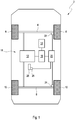
- FIG. 1 comprises a schematic representation of an embodiment of the system according to the invention when carrying out an embodiment of the method according to the invention.
- FIG. 1 shows a schematic representation of a trained here as a motor vehicle 2 with a front axle 4, on the front wheels 6 are arranged, and a rear axle 8, are arranged on the rear wheels 10, which touch a to be traveled by the vehicle 2 ground.
- this has at least one electric machine 12, which is designed to convert electrical energy from at least one battery 14 into mechanical energy and to provide at least one wheel 6, 10 and / or at least one axle 4, 8.
- a value of at least one electrical operating variable for example at least one electrical voltage and / or at least one electrical current, of at least one power electronics 16 for the at least one electric machine 12 is set.
- the likewise schematically illustrated embodiment of the system 18 according to the invention has at least one control unit 20 and at least one sensor 22, 24, 26 of the vehicle 2.
- Each sensor 22, 24, 26 is designed to detect a value of at least one operating variable or at least one operating parameter of the vehicle 2 and to transmit it to the control unit 20.
- at least two sensors 22, 24 are each associated with at least one wheel 6, 10 and / or at least one axle 4, 8 and designed as the at least one operating variable a slip between at least one tire mounted on at least one wheel 6, 10 , and the ground and / or a load acting on the at least one axis 4, 6 to determine.
- At least one further sensor 26 is associated with at least one control element 28 of the vehicle 2, which is operable by a driver of the vehicle 2, whereby at least one value, usually at least one desired value, is predetermined by the driver for at least one operating variable, this value detected by the at least one further sensor 26 and the control unit 20 provided.
- the driver it is possible for the driver to set, for example change, the operating state of the vehicle 2 by setting, for example changing, the value of the at least one operating variable.
- the value of the at least one operating variable of the vehicle is detected by the at least one sensor 22, 24, 26 at a starting time.
- This is, for example, a value of the at least one operating variable formed as an actual value, which results during the operation of the vehicle 2 at the start time, and is detected by the first or second sensor 22, 24.
- the value of the at least one operating variable is designed as a desired value, which is predetermined by the driver by operating the at least one operating element 28 and detected by the further third sensor 26.
- the value determined and / or detected at the start time, ie the desired value and / or the actual value, of the at least one operating variable is transmitted from the at least one sensor 22, 24, 26 to the control unit 20.
- a profile of the value of the at least one operating variable and thus also a current time change or derivative of the value or the course of the value of the at least one operating variable is monitored, for example, during a time interval and transmitted to the start time.
- the controller 20 predicts a value of the at least one operating variable to be expected at a target time, which in turn results in a value of the torque of the at least one electric machine 12 at the target time already predicted at the start time.
- a pair of values for two streams i. H. the current for the magnetization and a current for the torque, adjusted and adjusted.
- This pair of mutually correlated values for the two currents is adjustable using a map stored in the controller 20, the map being a function of a value for at least one of the two streams, eg the pair of values for both Currents describing at least one amount of operation with which the change in torque is predicted.
- a continuous adaptation of an optimal pair or an optimal pairing of the currents, d. H. the current for the magnetization and the torque-forming current is performed in software by maps or iterating search methods, i. H. any change in torque results in a new calculation or current setpoint calculation for setpoints of the pair of currents.
- the continuous adaptation of the calculation of the setpoint values for at least one of the currents is performed at an intermediate time after the start time and before the target time.
- the method is independent of adjusting a loss-optimal current for the magnetization.
- the method is provided for magnetizing the at least one electric machine 12 before commanding a desired value for the torque.
- the calculation or current setpoint calculation of the setpoint values for the currents then takes over the continuous adjustment of the pair of currents on the basis of the existing magnetization.
- the predictive magnetization can be z. B. with the maximum of the available current of a stator of the at least one electric machine 12 take place.
- Based on the actual setpoint of the torque determines the calculation of the setpoint values for the currents in the further course of the loss-optimized current for the magnetization with the advantage that already a magnetic flux is constructed and the torque can be made virtually no major delay.
- the proposed method of predictive magnetization also applies to externally excited synchronous machines, since the generation of a magnetic flux of a rotor of the at least one electric machine 12 via an excitation device also requires time and can be controlled predictively here.
Landscapes
- Engineering & Computer Science (AREA)
- Power Engineering (AREA)
- Transportation (AREA)
- Mechanical Engineering (AREA)
- Electric Propulsion And Braking For Vehicles (AREA)
Abstract
Description
- Die Erfindung betrifft ein Verfahren zum Betreiben mindestens einer Elektromaschine und ein System zum Betreiben mindestens einer Elektromaschine.
- Ein als Elektrofahrzeug ausgebildetes Fahrzeug kann mehrere Asynchronmaschinen als Traktionsantriebe aufweisen. Um für das Fahrzeug eine möglichst hohe Reichweite zu gewährleisten, werden die Asynchronmaschinen verlustminimal betrieben, wobei ein magnetischer Fluss an einen jeweiligen Betriebszustand bzw. Lastzustand angepasst wird. Falls ein Betriebszustand verändert wird, bspw. beim Einleiten eines Überholvorgangs oder einer Änderung einer Lastverteilung zwischen Vorder- und Hinterachse, wird der magnetische Fluss durch eine Maschinenregelung an ein neues Solldrehmoment angepasst, so dass Verluste der Asynchronmaschinen minimal gehalten werden. Ein zeitlicher Verlauf für ein Auf- und Abmagnetisieren der Asynchronmaschinen kann durch eine Exponentialfunktion beschrieben werden. Eine zu dieser Exponentialfunktion zugehörige Zeitkonstante, bspw. Rotorzeitkonstante, ist masch inenspezifisch.
- Allerdings wird für das Aufmagnetisieren der Asynchronmaschinen eine gewisse Zeit benötigt. Soll eine Veränderung des Betriebszustands, d. h. in diesem Fall des Drehmoments, möglichst schnell erfolgen, muss ein dafür notwendiger magnetischer Fluss bereits eingeregelt sein. Wird der notwendige magnetische Fluss jedoch permanent eingestellt, wird ein dafür notwendiger Magnetisierungsstrom für alle anderen Betriebszustände unnötige Verluste verursachen. Diese unerwünschten Verluste und der Wunsch nach einer kurzen Einregelzeit für das Drehmoment ergeben somit einen Zielkonflikt zwischen einer Effizienz und einer Dynamik des Drehmoments.
- Ein Asynchronmotor mit einer je nach einer Belastung selbsttätig einstellbaren Leistung ist aus der Druckschrift
CH 170 198 A - Die Druckschrift
DE 1 538 300 A1 beschreibt ein Steuergerät zum Festhalten einer Welle eines Stellmotors in einer einstellbaren Winkellage mit einem Schalter, der von einer Nockenscheibe betätigbar ist. - Die Druckschrift
DE 103 18 246 A1 beschreibt ein Verfahren zur Steuerung der Bewegung eines Ankers eines elektromagnetischen Aktuators zur Betätigung eines Gaswechselventils einer Brennkraftmaschine für ein Kraftfahrzeug. - Vor diesem Hintergrund war es eine Aufgabe, ein Drehmoment einer Elektromaschine bedarfsgerecht einzustellen.
- Diese Aufgabe wird durch ein Verfahren und ein System mit den Merkmalen der unabhängigen Patentansprüche gelöst. Ausgestaltungen des Verfahrens und des Systems gehen aus den abhängigen Patentansprüchen sowie der Beschreibung hervor.
- Das erfindungsgemäße Verfahren ist zum Betreiben mindestens einer Elektromaschine vorgesehen, die zum Antreiben eines Fahrzeugs ausgebildet ist. Dabei wird ein Wert für mindestens eine Betriebsgröße des Fahrzeugs, die mindestens einen Betriebszustand, bspw. einen Lastzustand, des Fahrzeugs beschreibt, ermittelt. Aus diesem Wert der mindestens einen Betriebsgröße wird eine Änderung eines Drehmoments der mindestens einen Elektromaschine, bspw. aufgrund einer Dynamikanforderung, die an die mindestens eine Elektromaschine gestellt wird, zu einem Zielzeitpunkt vorhergesagt. Ein Strom für eine Magnetisierung der mindestens einen Elektromaschine wird bereits vor dem Zielzeitpunkt eingestellt, wobei der Wert des Stroms für die Magnetisierung erst zu dem bzw. an dem Zielzeitpunkt auf einen Wert angepasst und verändert wird.
- Ergänzend ist es möglich, neben dem Wert des Stroms für die Magnetisierung auch einen Wert für einen Strom für das Drehmoment, das zu dem Zielzeitpunkt erforderlich ist, bereits vor dem Zielzeitpunkt einzustellen und zu dem Zielzeitpunkt anzupassen und/oder zu verändern. Somit ist es möglich, ein Paar aus Werten für zwei Ströme, nämlich den Wert für den Strom für die Magnetisierung und den Wert für den Strom für das Drehmoment abhängig von dem Wert des Drehmoments, der zu dem Zielzeitpunkt über die mindestens eine Betriebsgröße vorhergesagt wird, vor dem Zielzeitpunkt einzustellen und zu dem Zielzeitpunkt anzupassen und/oder zu verändern.
- In Ausgestaltung wird ausgehend von einem aktuellen Startzeitpunkt der zukünftige Zielzeitpunkt ermittelt und/oder definiert bzw. festgelegt. Ausgehend von einem jeweiligen Wert der mindestens einen Betriebsgröße, bspw. aufgrund eines zeitlichen Verlaufs des Werts und ggf. aufgrund einer zeitlichen Änderung bzw. Ableitung des Verlaufs des Werts der mindestens einen Betriebsgröße, zu dem aktuellen Startzeitpunkt wird die Änderung des Drehmoments, das von der mindestens einen Betriebsgröße abhängig ist, an dem bzw. zu dem Zielzeitpunkt prädikativ errechnet und somit vorhergesagt. Dabei wird bereits zu dem Startzeitpunkt die zu dem Zielzeitpunkt zu erwartende Änderung des Drehmoments ermittelt. Der Strom für die Magnetisierung und der Strom für das Drehmoment der mindestens einen Elektromaschine sind Betriebsgrößen, die das Drehmoment ebenfalls beeinflussen. Die erforderlichen Werte des Stroms für die Magnetisierung und des Stroms für das Drehmoment werden bereits zu dem Startzeitpunkt berechnet und somit ebenfalls prognostiziert. Die Werte für den Strom für die Magnetisierung und das Drehmoment werden zu einem Zwischenzeitpunkt nach dem Startzeitpunkt und vor dem Zielzeitpunkt eingestellt und nachfolgend zu dem Zielzeitpunkt verändert sowie an die zu dem Zielzeitpunkt prognostizierte und/oder erwartete Änderung des Drehmoments der mindestens einen Elektromaschine angepasst.
- Aufgrund des Betriebszustands wird eine Wahrscheinlichkeit für die Änderung des Drehmoments zu dem Zielzeitpunkt ermittelt, wobei der Strom für die Magnetisierung und/oder das Drehmoment eingestellt wird bzw. werden, wenn die Wahrscheinlichkeit mindestens so groß wie ein hierfür vorgesehener Schwellwert ist.
- Ein Wert der mindestens einen Betriebsgröße bzw. mindestens eines entsprechenden Betriebsparameters des Fahrzeugs wird üblicherweise durch mindestens einen Sensor des Fahrzeugs erfasst und/oder ermittelt, wobei der Verlauf der mindestens einen Betriebsgröße aufgrund ermittelter Werte von einem Steuergerät des Fahrzeugs überwacht wird. Ein jeweiliger Betriebszustand des Fahrzeugs zu dem Startzeitpunkt ergibt sich aufgrund eines aktuellen Werts der mindestens einen Betriebsgröße. Dabei ist es möglich, dass von dem mindestens einen Sensor sich jeweils ergebende Istwerte als Werte der mindestens einen Betriebsgröße ermittelt und im Rahmen des Verfahrens berücksichtigt werden.
- Alternativ oder ergänzend werden auch Werte der mindestens einen Betriebsgröße von dem mindestens einen Sensor ermittelt, die als Sollwerte der mindestens einen Betriebsgröße ausgebildet sind und üblicherweise von einem Fahrer des Fahrzeugs durch Bedienen eines Bedienelements, bspw. eines Pedals, vorgegeben werden. Dabei ist einem jeweiligen Bedienelement ebenfalls ein Sensor zugeordnet, der den von dem Fahrer jeweils vorgesehenen Wert bzw. Sollwert für die mindestens eine Betriebsgröße erfasst.
- Ein jeweiliger Betriebszustand des Fahrzeugs ergibt sich aus dem jeweiligen Wert der mindestens einen Betriebsgröße, wobei der Betriebszustand aufgrund des jeweiligen Werts definiert wird. Falls der mindestens eine Wert der Betriebsgröße, bspw. zu dem vorgesehenen Startzeitpunkt, von dem Fahrer als Sollwert vorgegeben wird, wird der jeweils aktuelle Wert bzw. Istwert der mindestens einen Betriebsgröße üblicherweise an den vorgegebenen Sollwert bspw. über einen Regler, der als Komponente des Steuergeräts ausgebildet ist, angepasst. Unter Berücksichtigung einer hierbei durchzuführenden Regelung ist es in Ausgestaltung möglich, zu dem Zielzeitpunkt den Istwert als Wert der mindestens einen Betriebsgröße zu ermitteln, der aufgrund des zu dem Startzeitpunkt vorgegebenen Sollwerts eingeregelt wird. Dabei wird der sich zu dem Zielzeitpunkt ergebende Wert der mindestens einen Betriebsgröße bereits zu dem Startzeitpunkt aufgrund des vorgegebenen Sollwerts der mindestens einen Betriebsgröße und/oder eines aktuellen Werts bzw. Istwerts mindestens einer weiteren Betriebsgröße vorhergesagt. Unter Berücksichtigung dessen ist es bereits zu dem Zwischenzeitpunkt möglich, den Strom für die Magnetisierung und/oder das Drehmoment prädikativ auf den jeweils vorgesehenen Wert einzustellen und diesen Wert zu dem Zielzeitpunkt zu verändern und somit anzupassen.
- In einer möglichen Ausgestaltung des Verfahrens wird neben dem Strom für die Magnetisierung auch der Strom zum Bilden des Drehmoments der mindestens einen Elektromaschine eingestellt. Dabei ist jeweils einem Wert des Stroms für die Magnetisierung der mindestens einen Elektromaschine ein Wert für den Strom zum Bilden des Drehmoments der mindestens einen Elektromaschine zugeordnet. Außerdem wird eine Paarung bzw. ein Paar für Werte dieser beiden Ströme für die Magnetisierung und zum Bilden des Drehmoments im Rahmen einer Stromsollwertberechnung kontinuierlich angepasst, was rechnergestützt unter Berücksichtigung von Kennfeldern und/oder von iterierenden Suchverfahren durchgeführt wird. Dabei ist es möglich, bspw. ein Kennfeld zu verwenden, das einen Zusammenhang zwischen dem Wert des Drehmoments und dem Paar aus Werten für die beiden Ströme, d. h. dem Strom für die Magnetisierung und dem Strom zum Bilden des Drehmoments, beschreibt. Somit ist jeweils einem Wert, bspw. einem Sollwert für das Drehmoment, ein Paar aus Werten für die beiden Ströme zugeordnet. Falls zu dem Startzeitpunkt aufgrund des Werts der mindestens einen Betriebsgröße des Fahrzeugs der Wert für das Drehmoment und/oder dessen Änderung für den Zielzeitpunkt vorausgesagt wird, wird bspw. unter Berücksichtigung des mindestens einen Kennfelds der Wert für den Strom zur Magnetisierung und der Wert des Stroms zum Bilden des Magnetfelds berechnet, wobei das Paar für die beiden Werte des Stroms dem zu dem Zielzeitpunkt zu erwartenden Wert des Drehmoments zugeordnet wird. Hierbei ist es möglich, aktuelle Werte des Stroms zu erfassen sowie zukünftig zu dem Zielzeitpunkt zu erwartende Werte des Drehmoments kontinuierlich vorherzusagen und Werte zum kontinuierlichen Anpassen der Ströme abhängig von den zu erwartenden Werten des Drehmoments kontinuierlich im Rahmen der Stromsollwertberechnung zu berechnen und somit kontinuierlich anzupassen.
- Durch den Strom zum Magnetisieren wird die mindestens eine Elektromaschine bereits vor dem Zielzeitpunkt aufmagnetisiert, bevor der Sollwert für das Drehmoment zu dem Zielzeitpunkt angefordert wird und/oder erforderlich ist. Aufgrund der Berechnung bzw. Stromsollwertberechnung der Sollwerte für die beiden Ströme wird anhand einer bestehenden Magnetisierung der mindestens einen Elektromaschine das Paar bzw. die Paarung der Werte für die Ströme kontinuierlich eingestellt. Dabei ist es bspw. möglich, ein prädikatives Aufmagnetisieren unter Berücksichtigung eines Maximums eines zur Verfügung stehenden Werts des Stroms eines Stators der mindestens einen Elektromaschine einzustellen. Anhand eines tatsächlichen Werts bzw. Sollwerts des Drehmoments wird über die Berechnung der Werte bzw. Sollwerte für die beiden Ströme in einem weiteren Verlauf ein verlustoptimaler Wert für den Strom zur Magnetisierung eingestellt, wobei sich unter anderem ergibt, dass dadurch bereits vor dem Zielzeitpunkt ein magnetischer Fluss aufgebaut wird und ein erforderliches Drehmoment für die mindestens eine Elektromaschine zu dem Zielzeitpunkt ohne größeren zeitlichen Verzug gestellt wird.
- Das vorgeschlagene Verfahren, mit dem es möglich ist, die mindestens eine Elektromaschine prädikativ aufzumagnetisieren, ist auch für eine fremderregte Synchronmaschine durchführbar, da bei dieser ein Erzeugen eines magnetischen Flusses eines Rotors über eine Erregereinrichtung ebenfalls Zeit benötigt und mit dem Verfahren prädikativ steuerbar ist.
- Der Wert des Stroms für die Magnetisierung und/oder das Drehmoment wird bzw. werden durch Einstellen und Ändern des hierfür vorgesehenen Werts erhöht oder reduziert. Der Wert des Stroms für die Magnetisierung und der Wert des Stroms für das Drehmoment bilden in Ausgestaltung das Paar für Werte der beiden Ströme, wobei diese in der Regel zueinander korrelierten Werte über das Kennfeld von einem hierzu korrelierten Wert für das bspw. zu erwartende bzw. erforderliche Drehmoment abhängig sind.
- Der Wert für die mindestens eine Betriebsgröße und somit der mindestens eine Betriebszustand wird mit mindestens einem Sensor des Fahrzeugs zu dem Startzeitpunkt ermittelt und/oder von einem Fahrer des Fahrzeugs durch Bedienen des Bedienelements vorgegeben und/oder eingestellt.
- Das Verfahren wird für mindestens eine Elektromaschine durchgeführt, die als Asynchronmaschine und/oder fremderregte Synchronmaschine ausgebildet ist.
- Außerdem wird eine Zeitabhängigkeit der Magnetisierung mit einer Exponentialfunktion beschrieben und/oder ist von einer Rotorzeitkonstante der mindestens einen Elektromaschine abhängig.
- In Ausgestaltung wird der Wert eines Schlupfs von mindestens einem Rad des Fahrzeugs als die mindestens eine Betriebsgröße ermittelt. Weiterhin ist es möglich, den Unterschied eines Schlupfs unterschiedlicher Räder und/oder Achsen zu berücksichtigen und zumindest den Wert des Stroms für die Magnetisierung und ggf. auch den Wert des Stroms für das Drehmoment abhängig hiervon einzustellen und/oder zu ändern. Alternativ oder ergänzend wird als der mindestens eine Betriebsparameter eine Last einer Achse und der Wert für mindestens einen Strom, d. h. des Stroms für die Magnetisierung und ggf. auch des Stroms für das Drehmoment, aufgrund eines Unterschieds zwischen Lasten der Achsen bzw. einer Verteilung der Last auf die Achsen eingestellt und/oder verändert.
- Das erfindungsgemäße System ist zum Betreiben mindestens einer Elektromaschine ausgebildet, die zum Antreiben eines Fahrzeugs ausgebildet ist. Das System weist ein Steuergerät auf, das dazu ausgebildet ist, aufgrund eines ermittelten Werts für mindestens eine Betriebsgröße des Fahrzeugs, die mindestens einen Betriebszustand des Fahrzeugs beschreibt, zu einem Startzeitpunkt eine Änderung eines Drehmoments der mindestens einen Elektromaschine zu einem Zielzeitpunkt vorherzusagen. Das Steuergerät ist weiterhin dazu ausgebildet, zu veranlassen, dass ein Strom für eine Magnetisierung der mindestens einen Elektromaschine nach dem Startzeitpunkt und vor dem Zielzeitpunkt auf einen Wert eingestellt wird, und dass der Wert des Stroms für die Magnetisierung erst zu dem Zielzeitpunkt angepasst und/oder verändert, bspw. erhöht oder reduziert, wird.
- In Ausgestaltung ist es ergänzend möglich, von dem Steuergerät neben dem Wert des Stroms für die Magnetisierung ergänzend auch einen Wert eines Stroms für das Drehmoment der mindestens einen Elektromaschine bereits vor dem Zielzeitpunkt einzustellen und zu dem Zielzeitpunkt anzupassen und/oder zu verändern.
- Das System weist mindestens eine Leistungselektronik auf, die der mindestens einen Elektromaschine zugeordnet und dazu ausgebildet ist, der mindestens einen Elektromaschine den Strom für die Magnetisierung sowie den Strom für das Drehmoment bereitzustellen. Das Steuergerät ist dazu ausgebildet, der mindestens einen Leistungselektronik den Wert des Stroms für die Magnetisierung sowie für das Drehmoment vorzugeben.
- Außerdem weist das System mindestens einen Sensor auf, der dazu ausgebildet ist, den Wert der mindestens einen Betriebsgröße des Fahrzeugs zu ermitteln und dem Steuergerät bereitzustellen. Hierbei ist es möglich, dass der mindestens eine Sensor bspw. mindestens einer Achse und/oder mindestens einem Rad als Komponente des Fahrzeugs zugeordnet und dazu ausgebildet ist, einen Wert, in der Regel einen Istwert, der Betriebsgröße der Komponente zu erfassen.
- Mit dem Verfahren und dem System ist es möglich, ein Fahrzeug durch prädiktive bzw. vorausschauende Aufmagnetisierung der Asynchronmaschine oder fremderregten Synchronmaschine, als Beispiele für die mindestens eine Elektromaschine, effizient und dynamisch zu betreiben.
- Um die mindestens eine Elektromaschine verlustoptimal zu betreiben, wird zunächst der jeweils zum Betriebszustand des Fahrzeugs optimal passende magnetische Fluss eingeregelt. Durch permanente Auswertung des Betriebszustands anhand der mindestens einen Betriebsgröße des Fahrzeugs sowie des Fahrerwunsches während des Fahrbetriebs wird der Strom für die Magnetisierung und ggf. für das Drehmoment prädiktiv erhöht, sobald eine Situation erkannt wird, die eine hohe Dynamikanforderung an das Drehmoment wahrscheinlich macht. Damit ist der benötigte magnetische Fluss bereits zu dem Zielzeitpunkt für eine vollständige Dynamik des Drehmoments eingeregelt. Wird nachfolgend durch Auswertung des Betriebszustands des Fahrzeugs ein konstantes oder wenig dynamisches Verhalten des Drehmoments, bspw. für einen Sollwert des Drehmoments als Betriebsgröße der mindestens einen Elektromaschine, festgestellt, wird der Strom für die Magnetisierung und ggf. auch der Strom für das Drehmoment wieder auf einen verlustoptimalen Betrag reduziert.
- Somit ist es möglich, einen Zielkonflikt zwischen einer Effizienz und somit der Reichweite sowie einer hohen Dynamik des Drehmoments weitgehend aufzulösen. Der für den magnetischen Fluss notwendige Strom für die Magnetisierung und ggf. auch der Strom für das Drehmoment wird bzw. werden überwiegend verlustoptimal eingestellt und im Rahmen und/oder unter Berücksichtigung der Rotorzeitkonstante vor der eigentlichen Änderung des Sollwerts des Drehmoments prädiktiv erhöht.
- Für die Regelung der mindestens einen Elektromaschine wird in dem Steuergerät und/oder der Leistungselektronik mindestens eine Informationsschnittstelle bereitgestellt, die das prädiktive Erhöhen des Stroms für die Magnetisierung und ggf. für das Drehmoment ermöglicht. Die zur prädiktiven Erhöhung des Stroms zur Magnetisierung und ggf. zum Einstellen des Drehmoments erforderliche Information, bspw. über den Wert der mindestens einen Betriebsgröße, ist in mindestens einem Steuergerät, bspw. einem Steuergeräteverbund, des Fahrzeugs vorhanden. So ist zum Beispiel von einer erhöhten Dynamik des Drehmoments auszugehen, wenn vom Fahrer ein Sportmodus als Betriebszustand gewählt wird. Weiterhin wird von einer Erhöhung der Dynamik des Drehmoments ausgegangen und der Strom für die Magnetisierung und ggf. der Strom für das Drehmoment prädiktiv erhöht, wenn an der vorderen oder hinteren Achse ein größerer Schlupf als Betriebsgröße mindestens eines Rads erfasst wird und das Drehmoment auf nicht schlupfende Räder und/oder mindestens eine Achse schnell umzuverteilen ist. Hierbei wird eine Funktion zur Schätzung eines Reibwerts zwischen Reifen auf den Rädern und der befahrenen Fahrbahn als Betriebsgröße verwendet. Eine derartige Funktion ist auch in einem konventionellen Fahrzeug zum Durchführen einer Allradfunktion zum bedarfsgerechten Zuschalten der Hinterachse verwendbar.
- Durch die prädiktive Aufmagnetisierung wird der magnetische Fluss vor der eigentlichen Änderung der Last angepasst, wodurch eine Latenzzeit zwischen dem Sollwert und dem Istwert des Drehmoments möglichst klein gehalten wird.
- Weitere Vorteile und Ausgestaltungen der Erfindung ergeben sich aus der Beschreibung und der beiliegenden Zeichnung.
- Es versteht sich, dass die voranstehend genannten und die nachstehend noch zu erläuternden Merkmale nicht nur in der jeweils angegebenen Kombination, sondern auch in anderen Kombinationen oder in Alleinstellung verwendbar sind, ohne den Rahmen der vorliegenden Erfindung zu verlassen.
-
Figur 1 umfasst eine schematische Darstellung einer Ausführungsform des erfindungsgemäßen Systems bei Durchführung einer Ausführungsform des erfindungsgemäßen Verfahrens. -
Figur 1 zeigt in schematischer Darstellung ein hier als Kraftfahrzeug ausgebildetes Fahrzeug 2 mit einer vorderen Achse 4, an der vordere Räder 6 angeordnet sind, und einer hinteren Achse 8, an der hintere Räder 10 angeordnet sind, die einen von dem Fahrzeug 2 zu befahrenden Untergrund berühren. Zum Antreiben des Fahrzeugs 2 weist dieses mindestens eine Elektromaschine 12 auf, die dazu ausgebildet ist, elektrische Energie aus mindestens einer Batterie 14 in mechanische Energie umzuwandeln und mindestens einem Rad 6, 10 und/oder mindestens einer Achse 4, 8 bereitzustellen. Dabei wird ein Wert mindestens einer elektrischen Betriebsgröße, bspw. mindestens einer elektrischen Spannung und/oder mindestens eines elektrischen Stroms, von mindestens einer Leistungselektronik 16 für die mindestens eine Elektromaschine 12 eingestellt. - Die ebenfalls schematisch dargestellte Ausführungsform des erfindungsgemäßen Systems 18 weist mindestens ein Steuergerät 20 und mindestens einen Sensor 22, 24, 26 des Fahrzeugs 2 auf. Jeder Sensor 22, 24, 26 ist dazu ausgebildet, einen Wert mindestens einer Betriebsgröße bzw. mindestens eines Betriebsparameters des Fahrzeugs 2 zu erfassen und dem Steuergerät 20 zu übermitteln. Dabei sind mindestens zwei Sensoren 22, 24 jeweils mindestens einem Rad 6, 10 und/oder mindestens einer Achse 4, 8 zugeordnet und dazu ausgebildet, als die mindestens eine Betriebsgröße einen Schlupf zwischen mindestens einem Reifen, der auf mindestens einem Rad 6, 10 aufgezogen, und dem Untergrund und/oder eine Last, die auf die mindestens eine Achse 4, 6 wirkt, zu ermitteln. Mindestens ein weiterer Sensor 26 ist mindestens einem Bedienelement 28 des Fahrzeugs 2 zugeordnet, das von einem Fahrer des Fahrzeugs 2 bedienbar ist, wodurch durch den Fahrer mindestens ein Wert, in der Regel mindestens ein Sollwert, für mindestens eine Betriebsgröße vorgegeben wird, wobei dieser Wert von dem mindestens einen weiteren Sensor 26 erfasst und dem Steuergerät 20 bereitgestellt wird. Dabei ist es möglich, dass der Fahrer durch Einstellen, bspw. Ändern, des Werts der mindestens einen Betriebsgröße einen Betriebszustand des Fahrzeugs 2 einstellt, bspw. ändert.
- Bei der Ausführungsform des erfindungsgemäßen Verfahrens wird zu einem Startzeitpunkt der Wert der mindestens einen Betriebsgröße des Fahrzeugs von dem mindestens einen Sensor 22, 24, 26 erfasst. Dabei handelt es sich bspw. um einen als Istwert ausgebildeten Wert der mindestens einen Betriebsgröße, der sich während des Betriebs des Fahrzeugs 2 zu dem Startzeitpunkt ergibt, und von dem ersten oder zweiten Sensor 22, 24 erfasst wird.
- Alternativ oder ergänzend ist der Wert der mindestens einen Betriebsgröße als Sollwert ausgebildet, der durch den Fahrer durch Bedienen des mindestens einen Bedienelements 28 vorgegeben und von dem weiteren dritten Sensor 26 erfasst wird.
- Der zu dem Startzeitpunkt ermittelte und/oder erfasste Wert, d. h. der Sollwert und/oder der Istwert, der mindestens einen Betriebsgröße wird von dem mindestens einen Sensor 22, 24, 26 an das Steuergerät 20 übermittelt. Ein Verlauf des Werts der mindestens einen Betriebsgröße und somit auch eine aktuelle zeitliche Änderung bzw. Ableitung des Werts bzw. des Verlaufs des Werts der mindestens einen Betriebsgröße wird bspw. während eines Zeitintervalls überwacht und zu dem Startzeitpunkt übermittelt. Auf Grundlage dessen wird von dem Steuergerät 20 ein zu einem Zielzeitpunkt zu erwartender Wert der mindestens einen Betriebsgröße vorhergesagt, woraus sich wiederum ein Wert des Drehmoments der mindestens einen Elektromaschine 12 zu dem Zielzeitpunkt ergibt, der bereits zu dem Startzeitpunkt prognostiziert wird. Es ist weiterhin möglich, aufgrund eines zukünftig zu erwartenden Verlaufs des Drehmoments auch eine Änderung des Drehmoments zu dem Zielzeitpunkt vorherzusagen. Aufgrund dessen ist es möglich, bereits zu einem Zwischenzeitpunkt nach dem Startzeitpunkt und vor dem Zielzeitpunkt einen Wert für einen Strom zum Magnetisieren, üblicherweise zum Aufmagnetisieren der mindestens einen Elektromaschine 12, einzustellen und weiterhin zu dem Zielzeitpunkt anzupassen.
- Aufgrund dessen ist es in Ausgestaltung ergänzend möglich, bereits nach dem Startzeitpunkt und vor dem Zielzeitpunkt auch einen Wert für einen Strom zum Einstellen des Drehmoments für die mindestens eine Elektromaschine 12 einzustellen und zu dem Zielzeitpunkt anzupassen. Somit wird in Ausgestaltung ein Paar aus Werten für zwei Ströme, d. h. des Stroms für die Magnetisierung und eines Stroms für das Drehmoment, eingestellt und angepasst. Dieses Paar aus zueinander bspw. korrelierten Werten für die beiden Ströme ist unter Nutzung eines Kennfelds, das in dem Steuergerät 20 abgelegt ist, einstellbar, wobei das Kennfeld eine Abhängigkeit eines Werts für mindestens einen der beiden Ströme, bspw. des Paars aus Werten für beide Ströme, von der mindestens einen Betriebsgröße beschreibt, mit der die Änderung des Drehmoments vorhergesagt wird.
- Eine kontinuierliche Anpassung eines optimalen Paars bzw. einer optimalen Paarung der Ströme, d. h. des Stroms für die Magnetisierung und des drehmomentbildenden Stroms, wird in Software durch Kennfelder oder iterierende Suchverfahren durchgeführt, d. h. jegliche Änderung des Drehmoments führt zu einer neuen Berechnung bzw. Stromsollwertberechnung für Sollwerte des Paars an Strömen. Die kontinuierliche Anpassung der Berechnung der Sollwerte für mindestens einen der Ströme wird zu einem Zwischenzeitpunkt nach dem Startzeitpunkt und vor dem Zielzeitpunkt durchgeführt.
- Das Verfahren ist von einem Einregeln eines verlustoptimalen Stroms für die Magnetisierung unabhängig. Das Verfahren ist zum Aufmagnetisieren der mindestens einen Elektromaschine 12 vorgesehen, bevor ein Sollwert für das Drehmoment kommandiert wird. Die Berechnung bzw. Stromsollwertberechnung der Sollwerte für die Ströme übernimmt dann anhand der bestehenden Magnetisierung das kontinuierliche Einstellen des Paars der Ströme. Das prädiktive Aufmagnetisieren kann hierbei z. B. mit dem Maximum des zur Verfügung stehenden Stroms eines Stators der mindestens einen Elektromaschine 12 erfolgen. Anhand des tatsächlichen Sollwerts des Drehmoments ermittelt dann die Berechnung der Sollwerte für die Ströme im weiteren Verlauf den verlustoptimalen Strom für die Magnetisierung mit dem Vorteil, dass schon ein magnetischer Fluss aufgebaut ist und das Drehmoment faktisch ohne größeren Zeitverzug gestellt werden kann.
- Das vorgeschlagene Verfahren des prädiktiven Aufmagnetisierens gilt auch für fremderregte Synchronmaschinen, da hier das Erzeugen eines magnetischen Flusses eines Rotors der mindestens einen Elektromaschine 12 über eine Erregereinrichtung ebenfalls Zeit benötigt und prädiktiv gesteuert werden kann.
Claims (8)
- Verfahren zum Betreiben mindestens einer Elektromaschine (12), die zum Antreiben eines Fahrzeugs (2) ausgebildet ist, bei dem ein Wert für mindestens eine Betriebsgröße des Fahrzeugs (2) ermittelt wird, wobei aus dem Wert der mindestens einen Betriebsgröße eine Änderung eines Drehmoments der mindestens einen Elektromaschine zu einem Zielzeitpunkt vorhergesagt wird, wobei ein Strom für eine Magnetisierung der mindestens einen Elektromaschine (12) vor dem Zielzeitpunkt auf einen Wert eingestellt wird, wobei der Wert des Stroms für die Magnetisierung zu dem Zielzeitpunkt angepasst und verändert wird.
- Verfahren nach Anspruch 1, bei dem aufgrund des Werts der mindestens einen Betriebsgröße eine Wahrscheinlichkeit für die Änderung des Drehmoments zu dem Zielzeitpunkt ermittelt wird, wobei der Strom für die Magnetisierung eingestellt wird, wenn die Wahrscheinlichkeit mindestens so groß wie ein hierfür vorgesehener Schwellwert ist.
- Verfahren nach Anspruch 1 oder 2, bei dem der Wert für die mindestens eine Betriebsgröße mit mindestens einem Sensor (22, 24, 26) des Fahrzeugs (2) ermittelt wird.
- Verfahren nach einem der voranstehenden Ansprüche, das für mindestens eine Elektromaschine (12) durchgeführt wird, die als Asynchronmaschine oder fremderregte Synchronmaschine ausgebildet ist.
- Verfahren nach einem der voranstehenden Ansprüche, bei dem der Wert eines Schlupfs von mindestens einem Rad (6, 10) des Fahrzeugs (2) als die mindestens eine Betriebsgröße ermittelt wird.
- System zum Betreiben mindestens einer Elektromaschine (12), die zum Antreiben eines Fahrzeugs (2) ausgebildet ist, wobei das System (18) ein Steuergerät (20) aufweist, das dazu ausgebildet ist, aufgrund eines ermittelten Werts für mindestens eine Betriebsgröße des Fahrzeugs (2) eine Änderung eines Drehmoments der mindestens einen Elektromaschine (12) zu einem Zielzeitpunkt vorherzusagen, wobei das Steuergerät (20) weiterhin dazu ausgebildet ist, zu veranlassen, dass ein Strom für eine Magnetisierung der mindestens einen Elektromaschine (12) vor dem Zielzeitpunkt auf einen Wert eingestellt und der Wert des Stroms für die Magnetisierung zu dem Zielzeitpunkt verändert wird.
- System nach Anspruch 6, die mindestens eine Leistungselektronik (16) aufweist, die der mindestens einen Elektromaschine (12) zugeordnet und dazu ausgebildet ist, der mindestens einen Elektromaschine (12) den Strom für die Magnetisierung bereitzustellen, wobei das Steuergerät (20) dazu ausgebildet ist, der mindestens einen Leistungselektronik (16) den Wert des Stroms für die Magnetisierung vorzugeben.
- System nach Anspruch 6 oder 7, das mindestens einen Sensor (22, 24, 26) aufweist, der dazu ausgebildet ist, den Wert der mindestens einen Betriebsgröße des Fahrzeugs (2) zu ermitteln und dem Steuergerät (20) bereitzustellen.
Applications Claiming Priority (1)
| Application Number | Priority Date | Filing Date | Title |
|---|---|---|---|
| DE102017218661.5A DE102017218661A1 (de) | 2017-10-19 | 2017-10-19 | Verfahren zum Betreiben mindestens einer Elektromaschine |
Publications (2)
| Publication Number | Publication Date |
|---|---|
| EP3474436A1 true EP3474436A1 (de) | 2019-04-24 |
| EP3474436B1 EP3474436B1 (de) | 2022-09-07 |
Family
ID=62841915
Family Applications (1)
| Application Number | Title | Priority Date | Filing Date |
|---|---|---|---|
| EP18181074.8A Active EP3474436B1 (de) | 2017-10-19 | 2018-07-02 | Verfahren und system zum betreiben mindestens einer elektromaschine |
Country Status (4)
| Country | Link |
|---|---|
| US (1) | US10778133B2 (de) |
| EP (1) | EP3474436B1 (de) |
| CN (1) | CN109677275B (de) |
| DE (1) | DE102017218661A1 (de) |
Families Citing this family (1)
| Publication number | Priority date | Publication date | Assignee | Title |
|---|---|---|---|---|
| CN111186308B (zh) * | 2019-12-31 | 2021-07-27 | 合创汽车科技有限公司 | 电动汽车驱动转矩分配方法、装置和计算机设备 |
Citations (2)
| Publication number | Priority date | Publication date | Assignee | Title |
|---|---|---|---|---|
| DE102014213985A1 (de) * | 2014-07-17 | 2016-01-21 | Magna powertrain gmbh & co kg | Fahrzeug sowie Vorrichtungen und Verfahren zum Steuern eines felderregenden Stroms |
| DE102015015697A1 (de) * | 2015-12-04 | 2017-06-08 | Audi Ag | Verfahren zur Ansteuerung einer elektrischen Maschine für den Antrieb eines Kraftfahrzeugs und Kraftfahrzeug |
Family Cites Families (11)
| Publication number | Priority date | Publication date | Assignee | Title |
|---|---|---|---|---|
| CH170198A (de) | 1932-02-04 | 1934-06-30 | Sousedik Josef | Asynchronmotor mit selbsttätig einstellbarer Leistung je nach der Belastung. |
| CH444273A (de) | 1966-09-23 | 1967-09-30 | Bbc Brown Boveri & Cie | Steuergerät für einen Stellmotor |
| DE10318246A1 (de) | 2003-03-31 | 2004-11-11 | Bayerische Motoren Werke Ag | Verfahren zur Steuerung der Bewegung eines Ankers eines elektromagnetischen Aktuators |
| US8712650B2 (en) * | 2005-11-17 | 2014-04-29 | Invent.Ly, Llc | Power management systems and designs |
| JP4634321B2 (ja) * | 2006-02-28 | 2011-02-16 | 日立オートモティブシステムズ株式会社 | 電動4輪駆動車用制御装置 |
| US7960928B2 (en) * | 2008-10-15 | 2011-06-14 | Tesla Motors, Inc. | Flux controlled motor management |
| CN101549689A (zh) * | 2009-04-30 | 2009-10-07 | 清华大学 | 一种三轴驱动的混合动力车驱动转矩的控制方法 |
| US9387859B2 (en) * | 2012-09-20 | 2016-07-12 | Pioneer Corporation | Slip ratio estimation device and slip ratio estimation method |
| US9388758B2 (en) * | 2014-03-26 | 2016-07-12 | GM Global Technology Operations LLC | Model predictive control systems and methods for future torque changes |
| US20160090005A1 (en) * | 2014-03-10 | 2016-03-31 | Dean Drako | Distributed Torque Generation System and Method of Control |
| JP6729220B2 (ja) * | 2016-09-08 | 2020-07-22 | トヨタ自動車株式会社 | 車両用運転支援装置 |
-
2017
- 2017-10-19 DE DE102017218661.5A patent/DE102017218661A1/de not_active Withdrawn
-
2018
- 2018-07-02 EP EP18181074.8A patent/EP3474436B1/de active Active
- 2018-07-17 US US16/037,205 patent/US10778133B2/en active Active
- 2018-08-27 CN CN201810980921.7A patent/CN109677275B/zh active Active
Patent Citations (2)
| Publication number | Priority date | Publication date | Assignee | Title |
|---|---|---|---|---|
| DE102014213985A1 (de) * | 2014-07-17 | 2016-01-21 | Magna powertrain gmbh & co kg | Fahrzeug sowie Vorrichtungen und Verfahren zum Steuern eines felderregenden Stroms |
| DE102015015697A1 (de) * | 2015-12-04 | 2017-06-08 | Audi Ag | Verfahren zur Ansteuerung einer elektrischen Maschine für den Antrieb eines Kraftfahrzeugs und Kraftfahrzeug |
Also Published As
| Publication number | Publication date |
|---|---|
| EP3474436B1 (de) | 2022-09-07 |
| DE102017218661A1 (de) | 2019-04-25 |
| CN109677275A (zh) | 2019-04-26 |
| CN109677275B (zh) | 2022-04-19 |
| US10778133B2 (en) | 2020-09-15 |
| US20190123673A1 (en) | 2019-04-25 |
Similar Documents
| Publication | Publication Date | Title |
|---|---|---|
| DE102006006056B4 (de) | Leistungsregelungseinheit | |
| DE102013219085B4 (de) | Verfahren und Steuervorrichtung zum Betrieb eines straßengekoppelten Hybridfahrzeuges | |
| WO2010031678A1 (de) | Verfahren zur einstellung einer motorischen antriebseinrichtung in einem kraftfahrzeug | |
| DE102018200169B3 (de) | Verfahren zur Geschwindigkeitsregelung eines Kraftfahrzeugs | |
| EP1966021B1 (de) | Verfahren zum betreiben eines hybridfahrzeugs | |
| DE10336758A1 (de) | Leerlaufdrehzahl-Regelungssystem für ein Hybridfahrzeug | |
| DE102007050113A1 (de) | Verfahren zum Betreiben einer Antriebsvorrichtung, insbesondere Hybridantriebsvorrichtung | |
| WO2014029548A1 (de) | Steuervorrichtung für ein generatorisches bremssystem eines fahrzeugs und verfahren zum betreiben eines generatorischen bremssystems eines fahrzeugs | |
| DE102010018753A1 (de) | Kraftfahrzeug | |
| DE102014213985B4 (de) | Verfahren zum Steuern eines felderregenden Stroms | |
| EP2646303A1 (de) | Verfahren und vorrichtung zum antrieb eines kraftfahrzeuges | |
| WO2016119948A1 (de) | Steuervorrichtung und verfahren zur gemeinsamen regelung von asynchronmaschinen eines kraftfahrzeugs | |
| EP3474436B1 (de) | Verfahren und system zum betreiben mindestens einer elektromaschine | |
| DE10309326B4 (de) | Verfahren und Vorrichtung zur Steuerung eines Drehstromgenerators bei einem Kraftfahrzeug | |
| EP1531073B1 (de) | Verfahren zur Energierückgewinnung bei einem Fahrzeug | |
| WO2003055713A1 (de) | Verfahren und einrichtung zur regelung des antriebsmomentes nach einem lastwechsel bei hybridfahrzeugen | |
| DE102021100235A1 (de) | Steuerungssystem und -verfahren für hybridfahrzeuge | |
| DE102013017946B4 (de) | Verfahren zurn Betreiben einer Hybridantriebseinrichtung sowie entsprechende Hybridantriebseinrichtung | |
| DE102007027966A1 (de) | Antriebseinheit für ein Hybridfahrzeug und Verfahren zur Steuerung eines Hybridfahrzeugs | |
| DE102006013677A1 (de) | Verfahren zum Betreiben einer Antriebseinheit eines Hybridfahrzeugs | |
| EP4256692A1 (de) | Verfahren zum betreiben einer elektrischen maschine, vorrichtung zum betreiben einer elektrischen maschine, elektrisches antriebssystem | |
| DE102020128730B4 (de) | Verfahren zum Betreiben eines Kraftfahrzeugs sowie entsprechendes Kraftfahrzeug | |
| EP1998992B1 (de) | Verfahren zum betreiben eines hybridfahrzeugs | |
| DE102017201407A1 (de) | Verfahren zum Bereitstellen einer elektrischen Leistung für eine elektrische Antriebsmaschine eines Kraftfahrzeuges und ein diesbezügliches System und Kraftfahrzeug | |
| WO2011072965A1 (de) | Verfahren zum betreiben einer antriebseinrichtung sowie steuergerät für eine antriebseinrichtung |
Legal Events
| Date | Code | Title | Description |
|---|---|---|---|
| PUAI | Public reference made under article 153(3) epc to a published international application that has entered the european phase |
Free format text: ORIGINAL CODE: 0009012 |
|
| STAA | Information on the status of an ep patent application or granted ep patent |
Free format text: STATUS: THE APPLICATION HAS BEEN PUBLISHED |
|
| AK | Designated contracting states |
Kind code of ref document: A1 Designated state(s): AL AT BE BG CH CY CZ DE DK EE ES FI FR GB GR HR HU IE IS IT LI LT LU LV MC MK MT NL NO PL PT RO RS SE SI SK SM TR |
|
| AX | Request for extension of the european patent |
Extension state: BA ME |
|
| STAA | Information on the status of an ep patent application or granted ep patent |
Free format text: STATUS: REQUEST FOR EXAMINATION WAS MADE |
|
| 17P | Request for examination filed |
Effective date: 20191024 |
|
| RBV | Designated contracting states (corrected) |
Designated state(s): AL AT BE BG CH CY CZ DE DK EE ES FI FR GB GR HR HU IE IS IT LI LT LU LV MC MK MT NL NO PL PT RO RS SE SI SK SM TR |
|
| STAA | Information on the status of an ep patent application or granted ep patent |
Free format text: STATUS: EXAMINATION IS IN PROGRESS |
|
| 17Q | First examination report despatched |
Effective date: 20210412 |
|
| GRAP | Despatch of communication of intention to grant a patent |
Free format text: ORIGINAL CODE: EPIDOSNIGR1 |
|
| STAA | Information on the status of an ep patent application or granted ep patent |
Free format text: STATUS: GRANT OF PATENT IS INTENDED |
|
| INTG | Intention to grant announced |
Effective date: 20220607 |
|
| GRAS | Grant fee paid |
Free format text: ORIGINAL CODE: EPIDOSNIGR3 |
|
| GRAA | (expected) grant |
Free format text: ORIGINAL CODE: 0009210 |
|
| STAA | Information on the status of an ep patent application or granted ep patent |
Free format text: STATUS: THE PATENT HAS BEEN GRANTED |
|
| AK | Designated contracting states |
Kind code of ref document: B1 Designated state(s): AL AT BE BG CH CY CZ DE DK EE ES FI FR GB GR HR HU IE IS IT LI LT LU LV MC MK MT NL NO PL PT RO RS SE SI SK SM TR |
|
| REG | Reference to a national code |
Ref country code: GB Ref legal event code: FG4D Free format text: NOT ENGLISH |
|
| REG | Reference to a national code |
Ref country code: CH Ref legal event code: EP Ref country code: AT Ref legal event code: REF Ref document number: 1517892 Country of ref document: AT Kind code of ref document: T Effective date: 20220915 |
|
| REG | Reference to a national code |
Ref country code: DE Ref legal event code: R096 Ref document number: 502018010562 Country of ref document: DE |
|
| REG | Reference to a national code |
Ref country code: IE Ref legal event code: FG4D Free format text: LANGUAGE OF EP DOCUMENT: GERMAN |
|
| REG | Reference to a national code |
Ref country code: LT Ref legal event code: MG9D |
|
| REG | Reference to a national code |
Ref country code: NL Ref legal event code: MP Effective date: 20220907 |
|
| PG25 | Lapsed in a contracting state [announced via postgrant information from national office to epo] |
Ref country code: SE Free format text: LAPSE BECAUSE OF FAILURE TO SUBMIT A TRANSLATION OF THE DESCRIPTION OR TO PAY THE FEE WITHIN THE PRESCRIBED TIME-LIMIT Effective date: 20220907 Ref country code: RS Free format text: LAPSE BECAUSE OF FAILURE TO SUBMIT A TRANSLATION OF THE DESCRIPTION OR TO PAY THE FEE WITHIN THE PRESCRIBED TIME-LIMIT Effective date: 20220907 Ref country code: NO Free format text: LAPSE BECAUSE OF FAILURE TO SUBMIT A TRANSLATION OF THE DESCRIPTION OR TO PAY THE FEE WITHIN THE PRESCRIBED TIME-LIMIT Effective date: 20221207 Ref country code: LV Free format text: LAPSE BECAUSE OF FAILURE TO SUBMIT A TRANSLATION OF THE DESCRIPTION OR TO PAY THE FEE WITHIN THE PRESCRIBED TIME-LIMIT Effective date: 20220907 Ref country code: LT Free format text: LAPSE BECAUSE OF FAILURE TO SUBMIT A TRANSLATION OF THE DESCRIPTION OR TO PAY THE FEE WITHIN THE PRESCRIBED TIME-LIMIT Effective date: 20220907 Ref country code: FI Free format text: LAPSE BECAUSE OF FAILURE TO SUBMIT A TRANSLATION OF THE DESCRIPTION OR TO PAY THE FEE WITHIN THE PRESCRIBED TIME-LIMIT Effective date: 20220907 |
|
| PG25 | Lapsed in a contracting state [announced via postgrant information from national office to epo] |
Ref country code: HR Free format text: LAPSE BECAUSE OF FAILURE TO SUBMIT A TRANSLATION OF THE DESCRIPTION OR TO PAY THE FEE WITHIN THE PRESCRIBED TIME-LIMIT Effective date: 20220907 Ref country code: GR Free format text: LAPSE BECAUSE OF FAILURE TO SUBMIT A TRANSLATION OF THE DESCRIPTION OR TO PAY THE FEE WITHIN THE PRESCRIBED TIME-LIMIT Effective date: 20221208 |
|
| PG25 | Lapsed in a contracting state [announced via postgrant information from national office to epo] |
Ref country code: SM Free format text: LAPSE BECAUSE OF FAILURE TO SUBMIT A TRANSLATION OF THE DESCRIPTION OR TO PAY THE FEE WITHIN THE PRESCRIBED TIME-LIMIT Effective date: 20220907 Ref country code: RO Free format text: LAPSE BECAUSE OF FAILURE TO SUBMIT A TRANSLATION OF THE DESCRIPTION OR TO PAY THE FEE WITHIN THE PRESCRIBED TIME-LIMIT Effective date: 20220907 Ref country code: PT Free format text: LAPSE BECAUSE OF FAILURE TO SUBMIT A TRANSLATION OF THE DESCRIPTION OR TO PAY THE FEE WITHIN THE PRESCRIBED TIME-LIMIT Effective date: 20230109 Ref country code: ES Free format text: LAPSE BECAUSE OF FAILURE TO SUBMIT A TRANSLATION OF THE DESCRIPTION OR TO PAY THE FEE WITHIN THE PRESCRIBED TIME-LIMIT Effective date: 20220907 Ref country code: CZ Free format text: LAPSE BECAUSE OF FAILURE TO SUBMIT A TRANSLATION OF THE DESCRIPTION OR TO PAY THE FEE WITHIN THE PRESCRIBED TIME-LIMIT Effective date: 20220907 |
|
| PG25 | Lapsed in a contracting state [announced via postgrant information from national office to epo] |
Ref country code: SK Free format text: LAPSE BECAUSE OF FAILURE TO SUBMIT A TRANSLATION OF THE DESCRIPTION OR TO PAY THE FEE WITHIN THE PRESCRIBED TIME-LIMIT Effective date: 20220907 Ref country code: PL Free format text: LAPSE BECAUSE OF FAILURE TO SUBMIT A TRANSLATION OF THE DESCRIPTION OR TO PAY THE FEE WITHIN THE PRESCRIBED TIME-LIMIT Effective date: 20220907 Ref country code: IS Free format text: LAPSE BECAUSE OF FAILURE TO SUBMIT A TRANSLATION OF THE DESCRIPTION OR TO PAY THE FEE WITHIN THE PRESCRIBED TIME-LIMIT Effective date: 20230107 Ref country code: EE Free format text: LAPSE BECAUSE OF FAILURE TO SUBMIT A TRANSLATION OF THE DESCRIPTION OR TO PAY THE FEE WITHIN THE PRESCRIBED TIME-LIMIT Effective date: 20220907 |
|
| REG | Reference to a national code |
Ref country code: DE Ref legal event code: R097 Ref document number: 502018010562 Country of ref document: DE |
|
| PG25 | Lapsed in a contracting state [announced via postgrant information from national office to epo] |
Ref country code: NL Free format text: LAPSE BECAUSE OF FAILURE TO SUBMIT A TRANSLATION OF THE DESCRIPTION OR TO PAY THE FEE WITHIN THE PRESCRIBED TIME-LIMIT Effective date: 20220907 Ref country code: AL Free format text: LAPSE BECAUSE OF FAILURE TO SUBMIT A TRANSLATION OF THE DESCRIPTION OR TO PAY THE FEE WITHIN THE PRESCRIBED TIME-LIMIT Effective date: 20220907 |
|
| P01 | Opt-out of the competence of the unified patent court (upc) registered |
Effective date: 20230530 |
|
| PLBE | No opposition filed within time limit |
Free format text: ORIGINAL CODE: 0009261 |
|
| STAA | Information on the status of an ep patent application or granted ep patent |
Free format text: STATUS: NO OPPOSITION FILED WITHIN TIME LIMIT |
|
| PG25 | Lapsed in a contracting state [announced via postgrant information from national office to epo] |
Ref country code: DK Free format text: LAPSE BECAUSE OF FAILURE TO SUBMIT A TRANSLATION OF THE DESCRIPTION OR TO PAY THE FEE WITHIN THE PRESCRIBED TIME-LIMIT Effective date: 20220907 |
|
| 26N | No opposition filed |
Effective date: 20230608 |
|
| PG25 | Lapsed in a contracting state [announced via postgrant information from national office to epo] |
Ref country code: SI Free format text: LAPSE BECAUSE OF FAILURE TO SUBMIT A TRANSLATION OF THE DESCRIPTION OR TO PAY THE FEE WITHIN THE PRESCRIBED TIME-LIMIT Effective date: 20220907 |
|
| PG25 | Lapsed in a contracting state [announced via postgrant information from national office to epo] |
Ref country code: MC Free format text: LAPSE BECAUSE OF FAILURE TO SUBMIT A TRANSLATION OF THE DESCRIPTION OR TO PAY THE FEE WITHIN THE PRESCRIBED TIME-LIMIT Effective date: 20220907 |
|
| PG25 | Lapsed in a contracting state [announced via postgrant information from national office to epo] |
Ref country code: MC Free format text: LAPSE BECAUSE OF FAILURE TO SUBMIT A TRANSLATION OF THE DESCRIPTION OR TO PAY THE FEE WITHIN THE PRESCRIBED TIME-LIMIT Effective date: 20220907 |
|
| REG | Reference to a national code |
Ref country code: CH Ref legal event code: PL |
|
| REG | Reference to a national code |
Ref country code: BE Ref legal event code: MM Effective date: 20230731 |
|
| PG25 | Lapsed in a contracting state [announced via postgrant information from national office to epo] |
Ref country code: LU Free format text: LAPSE BECAUSE OF NON-PAYMENT OF DUE FEES Effective date: 20230702 |
|
| GBPC | Gb: european patent ceased through non-payment of renewal fee |
Effective date: 20230702 |
|
| PG25 | Lapsed in a contracting state [announced via postgrant information from national office to epo] |
Ref country code: LU Free format text: LAPSE BECAUSE OF NON-PAYMENT OF DUE FEES Effective date: 20230702 |
|
| REG | Reference to a national code |
Ref country code: IE Ref legal event code: MM4A |
|
| PG25 | Lapsed in a contracting state [announced via postgrant information from national office to epo] |
Ref country code: CH Free format text: LAPSE BECAUSE OF NON-PAYMENT OF DUE FEES Effective date: 20230731 Ref country code: GB Free format text: LAPSE BECAUSE OF NON-PAYMENT OF DUE FEES Effective date: 20230702 |
|
| PG25 | Lapsed in a contracting state [announced via postgrant information from national office to epo] |
Ref country code: IT Free format text: LAPSE BECAUSE OF FAILURE TO SUBMIT A TRANSLATION OF THE DESCRIPTION OR TO PAY THE FEE WITHIN THE PRESCRIBED TIME-LIMIT Effective date: 20220907 Ref country code: FR Free format text: LAPSE BECAUSE OF NON-PAYMENT OF DUE FEES Effective date: 20230731 Ref country code: BE Free format text: LAPSE BECAUSE OF NON-PAYMENT OF DUE FEES Effective date: 20230731 |
|
| PG25 | Lapsed in a contracting state [announced via postgrant information from national office to epo] |
Ref country code: IE Free format text: LAPSE BECAUSE OF NON-PAYMENT OF DUE FEES Effective date: 20230702 |
|
| PG25 | Lapsed in a contracting state [announced via postgrant information from national office to epo] |
Ref country code: IE Free format text: LAPSE BECAUSE OF NON-PAYMENT OF DUE FEES Effective date: 20230702 |
|
| REG | Reference to a national code |
Ref country code: AT Ref legal event code: MM01 Ref document number: 1517892 Country of ref document: AT Kind code of ref document: T Effective date: 20230702 |
|
| PG25 | Lapsed in a contracting state [announced via postgrant information from national office to epo] |
Ref country code: AT Free format text: LAPSE BECAUSE OF NON-PAYMENT OF DUE FEES Effective date: 20230702 |
|
| PG25 | Lapsed in a contracting state [announced via postgrant information from national office to epo] |
Ref country code: AT Free format text: LAPSE BECAUSE OF NON-PAYMENT OF DUE FEES Effective date: 20230702 |
|
| PG25 | Lapsed in a contracting state [announced via postgrant information from national office to epo] |
Ref country code: BG Free format text: LAPSE BECAUSE OF FAILURE TO SUBMIT A TRANSLATION OF THE DESCRIPTION OR TO PAY THE FEE WITHIN THE PRESCRIBED TIME-LIMIT Effective date: 20220907 |
|
| PG25 | Lapsed in a contracting state [announced via postgrant information from national office to epo] |
Ref country code: BG Free format text: LAPSE BECAUSE OF FAILURE TO SUBMIT A TRANSLATION OF THE DESCRIPTION OR TO PAY THE FEE WITHIN THE PRESCRIBED TIME-LIMIT Effective date: 20220907 |
|
| PG25 | Lapsed in a contracting state [announced via postgrant information from national office to epo] |
Ref country code: CY Free format text: LAPSE BECAUSE OF FAILURE TO SUBMIT A TRANSLATION OF THE DESCRIPTION OR TO PAY THE FEE WITHIN THE PRESCRIBED TIME-LIMIT; INVALID AB INITIO Effective date: 20180702 |
|
| PG25 | Lapsed in a contracting state [announced via postgrant information from national office to epo] |
Ref country code: HU Free format text: LAPSE BECAUSE OF FAILURE TO SUBMIT A TRANSLATION OF THE DESCRIPTION OR TO PAY THE FEE WITHIN THE PRESCRIBED TIME-LIMIT; INVALID AB INITIO Effective date: 20180702 |
|
| PGFP | Annual fee paid to national office [announced via postgrant information from national office to epo] |
Ref country code: DE Payment date: 20250731 Year of fee payment: 8 |
|
| PG25 | Lapsed in a contracting state [announced via postgrant information from national office to epo] |
Ref country code: TR Free format text: LAPSE BECAUSE OF FAILURE TO SUBMIT A TRANSLATION OF THE DESCRIPTION OR TO PAY THE FEE WITHIN THE PRESCRIBED TIME-LIMIT Effective date: 20220907 |