EP3474226A1 - Information processing device, system, information processing method, and storage medium - Google Patents
Information processing device, system, information processing method, and storage medium Download PDFInfo
- Publication number
- EP3474226A1 EP3474226A1 EP18200680.9A EP18200680A EP3474226A1 EP 3474226 A1 EP3474226 A1 EP 3474226A1 EP 18200680 A EP18200680 A EP 18200680A EP 3474226 A1 EP3474226 A1 EP 3474226A1
- Authority
- EP
- European Patent Office
- Prior art keywords
- images
- boundary
- predetermined
- display
- information processing
- Prior art date
- Legal status (The legal status is an assumption and is not a legal conclusion. Google has not performed a legal analysis and makes no representation as to the accuracy of the status listed.)
- Withdrawn
Links
Images


Classifications
-
- G—PHYSICS
- G06—COMPUTING OR CALCULATING; COUNTING
- G06T—IMAGE DATA PROCESSING OR GENERATION, IN GENERAL
- G06T3/00—Geometric image transformations in the plane of the image
- G06T3/40—Scaling of whole images or parts thereof, e.g. expanding or contracting
- G06T3/4038—Image mosaicing, e.g. composing plane images from plane sub-images
-
- H—ELECTRICITY
- H04—ELECTRIC COMMUNICATION TECHNIQUE
- H04N—PICTORIAL COMMUNICATION, e.g. TELEVISION
- H04N21/00—Selective content distribution, e.g. interactive television or video on demand [VOD]
- H04N21/20—Servers specifically adapted for the distribution of content, e.g. VOD servers; Operations thereof
- H04N21/21—Server components or server architectures
- H04N21/218—Source of audio or video content, e.g. local disk arrays
- H04N21/21805—Source of audio or video content, e.g. local disk arrays enabling multiple viewpoints, e.g. using a plurality of cameras
-
- G—PHYSICS
- G06—COMPUTING OR CALCULATING; COUNTING
- G06F—ELECTRIC DIGITAL DATA PROCESSING
- G06F3/00—Input arrangements for transferring data to be processed into a form capable of being handled by the computer; Output arrangements for transferring data from processing unit to output unit, e.g. interface arrangements
- G06F3/01—Input arrangements or combined input and output arrangements for interaction between user and computer
- G06F3/048—Interaction techniques based on graphical user interfaces [GUI]
- G06F3/0484—Interaction techniques based on graphical user interfaces [GUI] for the control of specific functions or operations, e.g. selecting or manipulating an object, an image or a displayed text element, setting a parameter value or selecting a range
- G06F3/0485—Scrolling or panning
-
- G—PHYSICS
- G06—COMPUTING OR CALCULATING; COUNTING
- G06T—IMAGE DATA PROCESSING OR GENERATION, IN GENERAL
- G06T7/00—Image analysis
- G06T7/50—Depth or shape recovery
- G06T7/55—Depth or shape recovery from multiple images
- G06T7/593—Depth or shape recovery from multiple images from stereo images
- G06T7/596—Depth or shape recovery from multiple images from stereo images from three or more stereo images
-
- H—ELECTRICITY
- H04—ELECTRIC COMMUNICATION TECHNIQUE
- H04N—PICTORIAL COMMUNICATION, e.g. TELEVISION
- H04N21/00—Selective content distribution, e.g. interactive television or video on demand [VOD]
- H04N21/40—Client devices specifically adapted for the reception of or interaction with content, e.g. set-top-box [STB]; Operations thereof
- H04N21/43—Processing of content or additional data, e.g. demultiplexing additional data from a digital video stream; Elementary client operations, e.g. monitoring of home network or synchronising decoder's clock; Client middleware
- H04N21/431—Generation of visual interfaces for content selection or interaction; Content or additional data rendering
-
- H—ELECTRICITY
- H04—ELECTRIC COMMUNICATION TECHNIQUE
- H04N—PICTORIAL COMMUNICATION, e.g. TELEVISION
- H04N21/00—Selective content distribution, e.g. interactive television or video on demand [VOD]
- H04N21/60—Network structure or processes for video distribution between server and client or between remote clients; Control signalling between clients, server and network components; Transmission of management data between server and client, e.g. sending from server to client commands for recording incoming content stream; Communication details between server and client
- H04N21/65—Transmission of management data between client and server
- H04N21/658—Transmission by the client directed to the server
-
- H—ELECTRICITY
- H04—ELECTRIC COMMUNICATION TECHNIQUE
- H04N—PICTORIAL COMMUNICATION, e.g. TELEVISION
- H04N23/00—Cameras or camera modules comprising electronic image sensors; Control thereof
- H04N23/60—Control of cameras or camera modules
- H04N23/698—Control of cameras or camera modules for achieving an enlarged field of view, e.g. panoramic image capture
-
- H—ELECTRICITY
- H04—ELECTRIC COMMUNICATION TECHNIQUE
- H04N—PICTORIAL COMMUNICATION, e.g. TELEVISION
- H04N23/00—Cameras or camera modules comprising electronic image sensors; Control thereof
- H04N23/95—Computational photography systems, e.g. light-field imaging systems
- H04N23/958—Computational photography systems, e.g. light-field imaging systems for extended depth of field imaging
- H04N23/959—Computational photography systems, e.g. light-field imaging systems for extended depth of field imaging by adjusting depth of field during image capture, e.g. maximising or setting range based on scene characteristics
-
- H—ELECTRICITY
- H04—ELECTRIC COMMUNICATION TECHNIQUE
- H04N—PICTORIAL COMMUNICATION, e.g. TELEVISION
- H04N5/00—Details of television systems
- H04N5/222—Studio circuitry; Studio devices; Studio equipment
- H04N5/262—Studio circuits, e.g. for mixing, switching-over, change of character of image, other special effects ; Cameras specially adapted for the electronic generation of special effects
- H04N5/265—Mixing
-
- H—ELECTRICITY
- H04—ELECTRIC COMMUNICATION TECHNIQUE
- H04N—PICTORIAL COMMUNICATION, e.g. TELEVISION
- H04N7/00—Television systems
- H04N7/18—Closed-circuit television [CCTV] systems, i.e. systems in which the video signal is not broadcast
- H04N7/181—Closed-circuit television [CCTV] systems, i.e. systems in which the video signal is not broadcast for receiving images from a plurality of remote sources
Definitions
- the present invention relates to an information processing device, a system, an information processing method, and a storage medium.
- Japanese Patent Application Laid-Open No. 2005-192057 proposes an imaging device that combines images captured by a plurality of imaging devices and generates a panoramic image of 360 degrees around the imaging device.
- a function of performing a predetermined process on a region set within a captured image may be implemented.
- a function of performing a process of determining whether or not a person has passed through a set region or a function of performing a process of detecting how many persons there are in a set region may be implemented.
- the predetermined process may not be suitably performed. In such a case, it is necessary to change a view angle of the imaging device or re-set a region to be an object of the predetermined process.
- a view angle of the imaging device or re-set a region to be an object of the predetermined process.
- An information processing device of the present invention includes: a setting unit that sets, on a combined image in which a plurality of images captured through a plurality of imaging units are combined, an object region which is a region to be an object of a predetermined process; and a display control unit that, when a boundary between images included in the plurality of images in the combined image is included in the object region set by the setting unit, performs a predetermined display process on a display unit.
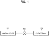
- FIG. 1 is a diagram illustrating an example of a system configuration of an information processing system of the present embodiment.
- the information processing system includes an imaging device 100 and a client device 101.
- the imaging device 100 and the client device 101 are communicably connected to each other via a network 102.
- the imaging device 100 is an imaging device that includes a plurality of imaging units and combines images captured through the plurality of imaging units to generate a wider angle image than in the case of an image being captured through a single imaging unit.
- the client device 101 is an information processing device such as a personal computer (PC), a server device, a tablet device, or the like that transmits, to the imaging device 100, various commands used for controlling the imaging device 100.
- PC personal computer
- the network 102 is a network such as the Internet, a wireless LAN, a wired LAN, or the like. Further, the client device 101 may supply power to the imaging device 100 via the network 102.
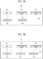
- FIG. 2A is a diagram illustrating an example of a hardware configuration of the imaging device 100.
- the imaging device 100 includes a CPU 201, a primary storage device 202, an auxiliary storage device 203, a network I/F 204, and an imaging unit 205. These components are communicably connected to each other via a system bus 206.
- the CPU 201 is a central processing unit that controls the imaging device 100.
- the primary storage device 202 is a storage device that functions as a work area of the CPU 201, a temporal storage area of data, or the like.
- the primary storage device 202 is implemented by using a storage medium such as a random access memory (RAM).
- the auxiliary storage device 203 is a storage device that stores various setting information, various programs, or information on images captured by the imaging device 100 or the like.
- the auxiliary storage device 203 is implemented by using a storage medium such as a read only memory (ROM), a hard disk drive (HDD), a solid state drive (SSD), or the like.
- the network I/F 204 is an interface used for communication with an external device such as the client device 101 via the network 102.
- the imaging unit 205 is an imaging unit that includes an image pickup device such as a CCD sensor, a CMOS sensor, or the like, a lens, and the like and captures the circumference.
- the imaging device 100 includes a plurality of imaging units 205.
- FIG. 2B is a diagram illustrating an example of a hardware configuration of the client device 101.
- the client device 101 includes a CPU 211, a primary storage device 212, an auxiliary storage device 213, an input I/F 214, an output I/F 215, and a network I/F 216. These components are communicably connected to each other via a system bus 217.
- the CPU 211 is a central processing unit that controls the client device 101.
- the primary storage device 212 is a storage device that functions as a work area of the CPU 211, a temporal storage area of data, or the like.
- the primary storage device 212 is implemented by using a storage medium such as a RAM.
- the auxiliary storage device 213 is a storage device that stores various setting information, various programs, information on images captured by the imaging device 100 or the like, information on control commands of the imaging device 100, or the like.
- the auxiliary storage device 213 is implemented by using a storage medium such as a ROM, an HDD, an SSD, or the like.
- the input I/F 214 is an interface used for connection to an input device such as a mouse, a keyboard, an operating unit in a touchscreen, or the like.
- the CPU 211 accepts input via the input I/F 214 from an input device connected to the input I/F 214.
- the output I/F 215 is an interface used for connection to an output device such as a monitor, a display, a speaker, a display unit in a touchscreen, or the like.
- the CPU 211 outputs information via the output I/F 215 to an output device connected to the output I/F 215.
- the network I/F 216 is an interface used for communication with an external device such as the imaging device 100 via the network 102.
- FIG. 3 is a diagram illustrating an example of a general arrangement of the imaging device 100.
- the imaging device 100 of the present embodiment includes the plurality of imaging units 205 that are radially arranged as depicted in FIG. 3 .
- Each range interposed between two dashed lines radially extended from each of the imaging units 205 illustrated in FIG. 3 illustrates a field of view of the imaging unit 205.
- the imaging device 100 generates an image (for example, a panoramic image or the like) that has a wider angle than an image captured by a single imaging unit by combining images captured through respective imaging units 205.
- the adjacent imaging units 205 are arranged to have overlapping capturing ranges.
- the imaging device 100 performs a combining process of images on an overlapping region of capturing ranges of the imaging units 205.
- FIG. 4 is a diagram illustrating an example of a combined image generated by the imaging device 100.
- a combined image 400 of FIG. 4 is a combined image generated by combining images captured through the four imaging units 205 by the imaging device 100.
- Each of combined boundaries 402 is a boundary in a combined image 400 between images captured through the imaging units 205.
- Each position of the combined boundaries 402 in the combined image 400 is a location where a position shift may occur.
- the number of combined boundaries 402 is three of the combined boundaries 402(a) to 402(c) but may be changed in accordance with the number of images to be used in combination. For example, as seen in the example of FIG. 4 , when images are horizontally arranged and combined and when n images are combined, the number of combined boundaries 402 is n-1.
- the CPU 201 of the imaging device 100 captures images through the plurality of imaging units 205, combines the captured images, and generates the combined image 400.
- the CPU 201 then transmits the generated combined image 400 to the client device 101.
- the CPU 211 causes a monitor connected to the output I/F 215 to display the combined image 400, for example. This enables the user to visually recognize the combined image 400 displayed on the monitor. Further, together with the combined image 400, the CPU 201 transmits, to the client device 101, information indicating which position in the combined image 400 each of the combined boundaries 402 is present.
- the CPU 211 displays the combined image 400 on the monitor and displays respective combined boundaries 402 on the combined image 400 displayed on the monitor based on the information on the position of the combined boundaries 402 received together with the combined image 400.
- the CPU 211 displays each of the combined boundaries 402 by dashed lines in the present embodiment but may display it by other display forms such as dot-dash lines. Further, the CPU 211 may not display each of the combined boundaries 402.
- the user can designate a region to be an object of a predetermined process with any size at any position within the combined image 400 displayed on the monitor by performing a drag operation by using a mouse connected to the input I/F 214, for example.
- the CPU 211 accepts designation of the region to be an object of a predetermined process based on the user operation through the mouse connected to the input I/F 214 and sets a region within the combined image 400 indicated by the accepted designation as the region to be an object of a predetermined process, for example.
- the region 401 of FIG. 4 is a set region to be an object of a predetermined process.
- image combination is unsuccessful such as because the captured ranges do not overlap with each other, and a position shift occurs at a subject 403 present on the combined boundary 402(c) of the combined image 400.
- FIG. 5 is a diagram illustrating an example of a combined image generated by the imaging device 100.
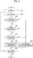
- FIG. 6 is a flowchart illustrating an example of the information processing system. An example of the process performed by the information processing system of the present embodiment will be described below by using FIG. 5 and FIG. 6 .
- the CPU 211 displays each of the combined boundaries 402 on the combined image 400 displayed on the monitor connected to the output I/F 215 by a dashed line.
- a predetermined process is a process which utilizes the shape of a predetermined object such as a process of detecting the number of persons within a region by detecting the shape of a person from the region, for example. While a predetermined object is a person in the present embodiment, it may be other objects such as an automobile, an animal, a cargo, or the like.
- another process is a process that does not utilize the shape of a predetermined object such as a process of detecting passage of a person based on a change of an image within a region.
- the region 500 is an example of an object region that is a region to be an object of a predetermined process.
- FIG. 5 illustrates a state where the region 500 to be an object of a predetermined process and the region 501 to be an object of another process are set on the combined image 400 illustrated in FIG. 4 .
- the CPU 211 selects one of the regions set within the combined image 400 (the region 500 and the region 501) as a selected region.
- the CPU 211 determines whether or not the selected region is an object of a process which utilizes the shape of a person. If the selected region is an object of a process which utilizes the shape of a person, the CPU 211 proceeds to the operation of S604, and if the selected region is not an object of a process which utilizes the shape of a person, the CPU 211 enters the operation of S606.
- the CPU 211 determines whether or not each of the combined boundaries 402 overlaps with the selected region. If any of the combined boundaries 402 overlaps with the selected region, the CPU 211 enters the operation of S605, and if none of the combined boundaries 402 overlaps with the selected region, the CPU 211 enters the operation of S606.
- the CPU 211 performs a predetermined display process on the monitor connected to the output I/F 215. This enables the CPU 211 to present to the user that the selected region may include the combined boundary 402 that is a portion on which a position shift may occur.
- the CPU 211 performs a display process of highlighting the combined boundary 402 overlapping with the selected region 500 by updating the display form of the combined boundary 402 that is determined to overlap with the selected region in S604 from a dashed line to a solid line.
- FIG. 5 illustrates a state where the display form of the combined boundary 402(a) overlapping with the region 500 is updated to the solid line. This enables the user to more easily visually recognize that the set region overlaps with the combined boundary 402. Further, the user is able to more easily recognize that the region set as an object of a process which utilizes the shape of a person includes the combined boundary 402 on which a position shift may occur.
- the operation of S605 is an example of a display control process.
- the user may take the following action. That is, for example, the user may instruct the imaging device 100 through the client device 101 to change each of the view angle of the imaging units 205 so that the region set as an object of a process which utilizes the shape of a person does not include the combined boundary 402.
- FIG. 7 illustrates the combined image 400 in which the view angle of the imaging unit 205 has been changed so that the region set as an object of a process which utilizes the shape of a person does not include the combined boundary 402. It can be seen that the region 500 does not overlap with the combined boundary 402. Further, for example, the user may change the position of the region set as an object of a process which utilizes the shape of a person to a position that does not include the combined boundary 402 through the client device 101.
- the CPU 211 determines not to change the display form of the combined boundary 402.
- the CPU 211 determines whether or not that the operations of S603 to S606 have been performed for all the regions set within the combined image 400. If the CPU 211 determines that the operations of S603 to S606 have been performed for all the regions set within the combined image 400, the process of FIG. 6 ends. If the CPU 211 determines that there is a region on which the operations of S603 to S606 have not yet been performed in the regions set within the combined image 400, the process proceeds to the operation of S602.
- the CPU 211 performs a display process of displaying, by a display form with a solid line, a line indicating the combined boundary 402 which overlaps with the set region and thereby highlights the line.
- the CPU 211 may perform a display process of displaying a line indicating the combined boundary 402 which overlaps with the set region by using predetermined color (for example, red) that is different from the color of lines indicating other combined boundaries 402 and thereby highlight the combined boundary 402 in interest.
- predetermined color for example, red
- the CPU 211 may blink the dashed line that indicates the combined boundary 402 which overlaps with the set region to highlight the combined boundary 402 in interest.
- the CPU 211 may perform a display process of displaying a line (for example, a straight line, a dashed line, or the like) that indicates the combined boundary 402 which overlaps with a region set as an object of a process which utilizes the shape of a person in S605, for example. Further, the CPU 211 may perform the following process in order to highlight the combined boundary 402 in S605. That is, the CPU 211 instructs the imaging device 100 to update the exposure values of two imaging units 205 that capture the combined boundary 402 to be highlighted to different values, respectively.
- a line for example, a straight line, a dashed line, or the like
- An exposure value is an index that represents an exposure level determined based on an aperture value and an exposure time.
- the CPU 211 acquires, from the imaging device 100, the combined image 400 in which images captured through the plurality of imaging units 205 including the imaging unit 205 having the updated exposure value are combined. Then, the CPU 211 may display the acquired combined image 400 on the monitor connected to the output I/F 215. Thereby, images different in brightness are arranged on the monitor interposing the combined boundary 402 to be highlighted, which enables the user to visually recognize which of the combined boundary 402 overlaps with the set region.
- the dashed line indicating the combined boundary 402 may be deleted.
- the information processing system when a region set as an object of a predetermined process overlaps with the combined boundary 402, the information processing system performs a predetermined display process on a monitor connected to the output I/F 215. That is, the information processing system can present to the user that a region set as an object of a predetermined process includes the combined boundary 402 that is a portion on which a position shift may occur. This enables the user to more easily recognize that the region set as an object of a predetermined process includes a portion on which a position shift may occur.
- the information processing system when a region set as an object of a predetermined process overlaps with the combined boundary 402, the information processing system performs a display process of changing a line indicating the combined boundary 402 in the overlapping portion from a dashed line to a solid line. In such a way, the information processing system performs a display process of changing the display form of a line indicating the combined boundary 402 in the overlapping portion and thereby presents to the user that the region set as an object of a predetermined process overlaps with the combined boundary 402.
- the field of view of the imaging unit 205 is wider for a farther region from the imaging unit 205.
- the fields of view of different imaging units 205 are more likely to overlap with each other for a region more distant from the imaging units 205.
- a position shift in the combined boundary 402 in the combined image 400 is more likely to occur for a shorter distance between a subject and the imaging unit 205 that captures the subject (hereafter, referred to as a subject distance) and is less likely to occur for a longer subject distance.
- the information processing system performs a predetermined display process when a region set as an object of a predetermined process overlaps with the combined boundary 402 and when the subject distance of a subject present in the region is less than or equal to a predetermined threshold.
- the system configuration of the information processing system of the present embodiment is the same as that of the first embodiment. Further, the hardware configuration of system components of the information processing system of the present embodiment is the same as that of the first embodiment.
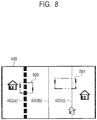
- FIG. 8 is a diagram illustrating an example of a combined image generated by the imaging device 100.
- FIG. 9 is a flowchart illustrating an example of the process performed by the information processing system of the present embodiment. An example of the process of the present embodiment will be described by using FIG. 8 and FIG. 9 . It is assumed here that combined boundaries between images are displayed by dashed lines in advance.
- S601 to S603, S606, and S607 of FIG. 9 are the same as those of FIG. 6 .
- the CPU 211 determines whether or not each of the combined boundaries 402 overlaps with the selected region. If the CPU 211 determines that any of the combined boundaries 402 overlaps with the selected region, the CPU 211 moves to the operation of S901, and if the CPU 211 determines that none of the combined boundaries 402 overlaps with the selected region, the CPU 211 moves to the operation of S606.
- the CPU 211 determines the subject distance for a subject present within a selected region. For example, the CPU 211 uses a Time Of Flight (TOF) scheme to determine the subject distance for a subject present within the selected region. For example, the CPU 211 irradiates the subject with a light through a light emitting unit included in the imaging unit 205 and receives a light reflected from the subject via the light receiving unit included in the imaging unit 205. The CPU 211 then determines the distance between the subject and the imaging unit 205 based on a difference between the time when irradiating the subject with a light and the time when receiving a light reflected from the subject.
- TOF Time Of Flight
- the CPU 211 calculates subject distances for respective imaging units 205 that capture the subject and determines the averaged value of the subject distances as a subject distance.
- the CPU 211 may select one out of the imaging units 205 that capture the subject, calculate a subject distance for the selected imaging unit 205, and determine the calculated subject distance as the final subject distance.
- the CPU 211 determines whether or not the determined subject distance is less than or equal to a predetermined threshold. If the CPU 211 determines that the determined subject distance is less than or equal to the predetermined threshold, the CPU 211 enters to the operation of S605, and if the CPU 211 determines that the determined subject distance is greater than the predetermined threshold, the CPU 211 enters the operation of S606.
- the CPU 211 presents that the selected region includes the combined boundary 402 by performing a display process of changing the display form so as to increase the width of a line which indicates the combined boundary 402 overlapping with the selected region.
- FIG. 8 illustrates a state where the width of a dashed line indicating the combined boundary 402(a) has been increased. It can be seen that the dashed line indicating the combined boundary 402(a) is wider than the dashed lines indicating the combined boundaries 402(b) and 402(c). Further, the CPU 211 may perform the same operation in S605 as that of the first embodiment.
- the information processing system when a region set as an object of a predetermined process overlaps with the combined boundary 402 and when the subject distance of a subject within the set region is included in a range less than or equal to a threshold, the information processing system performs a predetermined display process. In this way, in the present embodiment, when it is assumed that there is no influence of a position shift, the information processing system does not perform a process of presenting that the region to be an object of a predetermined process includes the combined boundary 402 on which a position shift may occur. This enables the information processing system to reduce the usage of the CPU 211 or the like that would otherwise be caused by an unnecessary process.
- the CPU 211 when a region set as an object of a predetermined process overlaps with the combined boundary 402 and when the subject distance of a subject within the set region is included in a range less than or equal to a threshold, the CPU 211 performs a predetermined display process.
- the CPU 211 may perform the following display process on the monitor connected to the output I/F 215. That is, the CPU 211 may determine the subject distance of a subject within a set region and perform a display process of changing the width of the combined boundary 402 overlapping with the set region to a width in accordance with the determined subject distance by the same process as the process illustrated in S901.
- the CPU 211 may change the width of the combined boundary 402 overlapping with a set region to a larger width for a smaller determined subject distance. This enables the user to visually recognize the degree of a position shift occurring on the combined boundary. Further, when the set region overlaps with the combined boundary 402 and when a subject distance of a subject within the set region is included in a range less than or equal to a threshold, the CPU 211 may perform the same display process.
- the information processing system when a region set as an object of a predetermined process overlaps with the combined boundary 402, the information processing system changes a line indicating the combined boundary 402 on the overlapping portion from a dashed line to a solid line. In the present embodiment, however, when a region set as an object of a predetermined process overlaps with the combined boundary 402, the information processing system performs a display process of displaying information indicating an error on the monitor connected to the output I/F 215.
- the system configuration of the information processing system of the present embodiment is the same as that of the first embodiment. Further, the hardware configuration of system components of the information processing system of the present embodiment is the same as that of the first embodiment.
- FIG. 10 is a flowchart illustrating an example of the process performed by the information processing system of the present embodiment.
- the operations of S601, S602, and S607 of FIG. 10 are the same as those of FIG. 6 .
- the CPU 211 determines whether or not the selected region is an object of a process which utilizes the shape of a person. If the selected region is an object of a process which utilizes the shape of a person, the CPU 211 proceeds to the operation of S604, and if the selected region is not an object of a process which utilizes the shape of a person, the CPU 211 ends the process of FIG. 10 .
- the CPU 211 determines whether or not each of the combined boundaries 402 overlaps with the selected region. If any of the combined boundaries 402 overlaps with the selected region, the CPU 211 enters the operation of S1001, and if none of the combined boundaries 402 overlaps with the selected region, the CPU 211 ends the process of FIG. 10 .
- the CPU 211 performs a display process of displaying information indicating an error on the monitor connected to the output I/F 215 and thereby presents to the user that a region set as an object of a predetermined process overlaps with the combined boundary 402.
- the information indicating an error is information indicating that a selected region is set in an unsuitable position, for example.
- the information indicating an error may be, for example, a character string, an image, or the like.
- the CPU 211 displays a character string indicating an error on the monitor connected to the output I/F 215, for example. Further, the CPU 211 may display a popup window to the monitor connected to the output I/F 215 for confirming whether or not to set the selected region without change though the selected region overlaps with the combined boundary 402.
- the information processing system can present more detailed information to the user by displaying information indicating an error.
- Embodiment(s) of the present invention can also be realized by a computer of a system or apparatus that reads out and executes computer executable instructions (e.g., one or more programs) recorded on a storage medium (which may also be referred to more fully as a 'non-transitory computer-readable storage medium') to perform the functions of one or more of the above-described embodiment(s) and/or that includes one or more circuits (e.g., application specific integrated circuit (ASIC)) for performing the functions of one or more of the above-described embodiment(s), and by a method performed by the computer of the system or apparatus by, for example, reading out and executing the computer executable instructions from the storage medium to perform the functions of one or more of the above-described embodiment(s) and/or controlling the one or more circuits to perform the functions of one or more of the above-described embodiment(s).
- computer executable instructions e.g., one or more programs
- a storage medium which may also be referred to more fully as
- the computer may comprise one or more processors (e.g., central processing unit (CPU), micro processing unit (MPU)) and may include a network of separate computers or separate processors to read out and execute the computer executable instructions.
- the computer executable instructions may be provided to the computer, for example, from a network or the storage medium.
- the storage medium may include, for example, one or more of a hard disk, a random-access memory (RAM), a read only memory (ROM), a storage of distributed computing systems, an optical disk (such as a compact disc (CD), digital versatile disc (DVD), or Blu-ray Disc (BD)TM), a flash memory device, a memory card, and the like.
- a part or whole of the functional configuration of the information processing system described above may be implemented in the imaging device 100 or the client device 101 as hardware.
- the imaging device 100 is a single imaging device including a plurality of imaging units 205.
- the imaging device 100 may be an information processing device such as a PC, a server device, or the like connected to a plurality of imaging devices.
- the imaging device 100 uses the plurality of connected external imaging devices as the imaging units 205 in the first to third embodiments.
- the information processing system performs a predetermined display process on a monitor connected to the output I/F 215.
- the information processing system may perform a predetermined display process on other display devices such as a display unit of a touchscreen connected to the output I/F 215.
- the information processing system may perform a predetermined display process on an external screen through a screen projector device connected to the output I/F 215.
- the client device 101 performs the process of FIG. 6 , FIG. 9 , or FIG. 10 .
- the imaging device 100 may perform the process of FIG. 6 , FIG. 9 , or FIG. 10 .
- the imaging device 100 performs the following process. That is, the imaging device 100 generates the combined image 400 and then transmits it to the client device 101.
- the client device 101 displays the received combined image 400 on a monitor connected to the output I/F 215, for example.
- the user uses a mouse or the like connected to the input I/F 214 to designate a region to be an object of a predetermined process, a region to be an object of another process, or the like.
- the client device 101 transmits position information on the designated region to the imaging device 100.
- the imaging device 100 then performs the process of S602 and the subsequent operations of FIG. 6 , FIG. 9 , or FIG. 10 based on the transmitted position information.
- the imaging device 100 transmits information on the changed display form to the client device 101 and instructs the client device 100 to change the display form of the combined boundary 402 on the monitor connected to the output I/F 215.
- the imaging device 100 transmits and thereby outputs error information to the client device 101 and instructs the client device 101 to display the error information on the monitor connected to the output I/F 215.
- An information processing device sets, on a combined image in which a plurality of images captured through a plurality of imaging units are combined, an object region which is a region to be an object of a predetermined process, and when a boundary between images included in the plurality of images in the combined image is included in the set object region, performs a predetermined display process on a display unit.
Landscapes
- Engineering & Computer Science (AREA)
- Multimedia (AREA)
- Signal Processing (AREA)
- Theoretical Computer Science (AREA)
- Physics & Mathematics (AREA)
- General Physics & Mathematics (AREA)
- General Engineering & Computer Science (AREA)
- Computer Vision & Pattern Recognition (AREA)
- Databases & Information Systems (AREA)
- Computing Systems (AREA)
- Human Computer Interaction (AREA)
- Studio Devices (AREA)
- Closed-Circuit Television Systems (AREA)
- Two-Way Televisions, Distribution Of Moving Picture Or The Like (AREA)
- Controls And Circuits For Display Device (AREA)
Abstract
Description
- The present invention relates to an information processing device, a system, an information processing method, and a storage medium.
- In an imaging device used for application of surveillance or the like, a broader range of monitoring is demanded. Accordingly, Japanese Patent Application Laid-Open No.
2005-192057 - On the other hand, in some imaging devices used for application of surveillance or the like, a function of performing a predetermined process on a region set within a captured image may be implemented. For example, a function of performing a process of determining whether or not a person has passed through a set region or a function of performing a process of detecting how many persons there are in a set region may be implemented.
- For example, when performing the process of detecting the number of persons within a set region, it is necessary to identify the shape of a person from an image of the set region. In a panoramic image generated by the imaging device disclosed in Japanese Patent Application Laid-Open No.
2005-192057 - As discussed above, when the region set as an object of a predetermined process includes a portion where a position shift may occur, the predetermined process may not be suitably performed. In such a case, it is necessary to change a view angle of the imaging device or re-set a region to be an object of the predetermined process. Thus, there is a demand for enabling the user to more easily recognize a situation where the region set as an object of a predetermined process includes a portion where a position shift may occur if such a situation arises.
- An information processing device of the present invention includes: a setting unit that sets, on a combined image in which a plurality of images captured through a plurality of imaging units are combined, an object region which is a region to be an object of a predetermined process; and a display control unit that, when a boundary between images included in the plurality of images in the combined image is included in the object region set by the setting unit, performs a predetermined display process on a display unit.
- Further features of the present invention will become apparent from the following description of exemplary embodiments with reference to the attached drawings.
-
-
FIG. 1 is a diagram illustrating an example of a system configuration of an image processing system. -
FIG. 2A and FIG. 2B are diagrams illustrating an example of a hardware configuration of an imaging device or the like. -
FIG. 3 is a diagram illustrating an example of a general arrangement of the imaging device. -
FIG. 4 is a diagram illustrating an example of a combined image. -
FIG. 5 is a diagram illustrating an example of a combined image. -
FIG. 6 is a flowchart illustrating an example of a process performed by an image processing system. -
FIG. 7 is a diagram illustrating an example of a combined image. -
FIG. 8 is a diagram illustrating an example of a combined image. -
FIG. 9 is a flowchart illustrating an example of a process performed by the image processing system. -
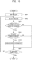
FIG. 10 is a flowchart illustrating an example of a process performed by the image processing system. - Preferred embodiments of the present invention will now be described in detail in accordance with the accompanying drawings.
-
FIG. 1 is a diagram illustrating an example of a system configuration of an information processing system of the present embodiment. The information processing system includes animaging device 100 and aclient device 101. Theimaging device 100 and theclient device 101 are communicably connected to each other via anetwork 102. Theimaging device 100 is an imaging device that includes a plurality of imaging units and combines images captured through the plurality of imaging units to generate a wider angle image than in the case of an image being captured through a single imaging unit. Theclient device 101 is an information processing device such as a personal computer (PC), a server device, a tablet device, or the like that transmits, to theimaging device 100, various commands used for controlling theimaging device 100. - The
network 102 is a network such as the Internet, a wireless LAN, a wired LAN, or the like. Further, theclient device 101 may supply power to theimaging device 100 via thenetwork 102. -
FIG. 2A is a diagram illustrating an example of a hardware configuration of theimaging device 100. Theimaging device 100 includes aCPU 201, aprimary storage device 202, anauxiliary storage device 203, a network I/F 204, and animaging unit 205. These components are communicably connected to each other via asystem bus 206. - The
CPU 201 is a central processing unit that controls theimaging device 100. Theprimary storage device 202 is a storage device that functions as a work area of theCPU 201, a temporal storage area of data, or the like. Theprimary storage device 202 is implemented by using a storage medium such as a random access memory (RAM). Theauxiliary storage device 203 is a storage device that stores various setting information, various programs, or information on images captured by theimaging device 100 or the like. Theauxiliary storage device 203 is implemented by using a storage medium such as a read only memory (ROM), a hard disk drive (HDD), a solid state drive (SSD), or the like. - The network I/F 204 is an interface used for communication with an external device such as the
client device 101 via thenetwork 102. Theimaging unit 205 is an imaging unit that includes an image pickup device such as a CCD sensor, a CMOS sensor, or the like, a lens, and the like and captures the circumference. Theimaging device 100 includes a plurality ofimaging units 205. -
FIG. 2B is a diagram illustrating an example of a hardware configuration of theclient device 101. Theclient device 101 includes aCPU 211, aprimary storage device 212, anauxiliary storage device 213, an input I/F 214, an output I/F 215, and a network I/F 216. These components are communicably connected to each other via asystem bus 217. - The
CPU 211 is a central processing unit that controls theclient device 101. Theprimary storage device 212 is a storage device that functions as a work area of theCPU 211, a temporal storage area of data, or the like. Theprimary storage device 212 is implemented by using a storage medium such as a RAM. Theauxiliary storage device 213 is a storage device that stores various setting information, various programs, information on images captured by theimaging device 100 or the like, information on control commands of theimaging device 100, or the like. Theauxiliary storage device 213 is implemented by using a storage medium such as a ROM, an HDD, an SSD, or the like. - The input I/F 214 is an interface used for connection to an input device such as a mouse, a keyboard, an operating unit in a touchscreen, or the like. The
CPU 211 accepts input via the input I/F 214 from an input device connected to the input I/F 214. The output I/F 215 is an interface used for connection to an output device such as a monitor, a display, a speaker, a display unit in a touchscreen, or the like. TheCPU 211 outputs information via the output I/F 215 to an output device connected to the output I/F 215. The network I/F 216 is an interface used for communication with an external device such as theimaging device 100 via thenetwork 102. -
FIG. 3 is a diagram illustrating an example of a general arrangement of theimaging device 100. - The
imaging device 100 of the present embodiment includes the plurality ofimaging units 205 that are radially arranged as depicted inFIG. 3 . Each range interposed between two dashed lines radially extended from each of theimaging units 205 illustrated inFIG. 3 illustrates a field of view of theimaging unit 205. Theimaging device 100 generates an image (for example, a panoramic image or the like) that has a wider angle than an image captured by a single imaging unit by combining images captured throughrespective imaging units 205. Theadjacent imaging units 205 are arranged to have overlapping capturing ranges. Theimaging device 100 performs a combining process of images on an overlapping region of capturing ranges of theimaging units 205. -
FIG. 4 is a diagram illustrating an example of a combined image generated by theimaging device 100. A combinedimage 400 ofFIG. 4 is a combined image generated by combining images captured through the fourimaging units 205 by theimaging device 100. Each of combinedboundaries 402 is a boundary in a combinedimage 400 between images captured through theimaging units 205. Each position of the combinedboundaries 402 in the combinedimage 400 is a location where a position shift may occur. In the example ofFIG. 4 , the number of combinedboundaries 402 is three of the combined boundaries 402(a) to 402(c) but may be changed in accordance with the number of images to be used in combination. For example, as seen in the example ofFIG. 4 , when images are horizontally arranged and combined and when n images are combined, the number of combinedboundaries 402 is n-1. - For example, when the
CPU 211 of theclient device 101 transmits a command for instructing generation of the combinedimage 400 to theimaging device 100, theCPU 201 of theimaging device 100 captures images through the plurality ofimaging units 205, combines the captured images, and generates the combinedimage 400. TheCPU 201 then transmits the generated combinedimage 400 to theclient device 101. TheCPU 211 causes a monitor connected to the output I/F 215 to display the combinedimage 400, for example. This enables the user to visually recognize the combinedimage 400 displayed on the monitor. Further, together with the combinedimage 400, theCPU 201 transmits, to theclient device 101, information indicating which position in the combinedimage 400 each of the combinedboundaries 402 is present. TheCPU 211 displays the combinedimage 400 on the monitor and displays respective combinedboundaries 402 on the combinedimage 400 displayed on the monitor based on the information on the position of the combinedboundaries 402 received together with the combinedimage 400. TheCPU 211 displays each of the combinedboundaries 402 by dashed lines in the present embodiment but may display it by other display forms such as dot-dash lines. Further, theCPU 211 may not display each of the combinedboundaries 402. - The user can designate a region to be an object of a predetermined process with any size at any position within the combined
image 400 displayed on the monitor by performing a drag operation by using a mouse connected to the input I/F 214, for example. TheCPU 211 accepts designation of the region to be an object of a predetermined process based on the user operation through the mouse connected to the input I/F 214 and sets a region within the combinedimage 400 indicated by the accepted designation as the region to be an object of a predetermined process, for example. Theregion 401 ofFIG. 4 is a set region to be an object of a predetermined process. - In the example
FIG. 4 , image combination is unsuccessful such as because the captured ranges do not overlap with each other, and a position shift occurs at a subject 403 present on the combined boundary 402(c) of the combinedimage 400. -
FIG. 5 is a diagram illustrating an example of a combined image generated by theimaging device 100. Further,FIG. 6 is a flowchart illustrating an example of the information processing system. An example of the process performed by the information processing system of the present embodiment will be described below by usingFIG. 5 andFIG. 6 . In the present embodiment, theCPU 211 displays each of the combinedboundaries 402 on the combinedimage 400 displayed on the monitor connected to the output I/F 215 by a dashed line. - The process of
FIG. 6 will be described. - In S601, the
CPU 211 sets aregion 500 to be an object of a predetermined process and aregion 501 to be an object of another process on the combinedimage 400 based on the user operation through the input device connected to the input I/F 214. In the present embodiment, a predetermined process is a process which utilizes the shape of a predetermined object such as a process of detecting the number of persons within a region by detecting the shape of a person from the region, for example. While a predetermined object is a person in the present embodiment, it may be other objects such as an automobile, an animal, a cargo, or the like. Further, in the present embodiment, another process is a process that does not utilize the shape of a predetermined object such as a process of detecting passage of a person based on a change of an image within a region. Theregion 500 is an example of an object region that is a region to be an object of a predetermined process.FIG. 5 illustrates a state where theregion 500 to be an object of a predetermined process and theregion 501 to be an object of another process are set on the combinedimage 400 illustrated inFIG. 4 . - In S602, the
CPU 211 selects one of the regions set within the combined image 400 (theregion 500 and the region 501) as a selected region. - In S603, the
CPU 211 determines whether or not the selected region is an object of a process which utilizes the shape of a person. If the selected region is an object of a process which utilizes the shape of a person, theCPU 211 proceeds to the operation of S604, and if the selected region is not an object of a process which utilizes the shape of a person, theCPU 211 enters the operation of S606. - In S604, the
CPU 211 determines whether or not each of the combinedboundaries 402 overlaps with the selected region. If any of the combinedboundaries 402 overlaps with the selected region, theCPU 211 enters the operation of S605, and if none of the combinedboundaries 402 overlaps with the selected region, theCPU 211 enters the operation of S606. - In S605, the
CPU 211 performs a predetermined display process on the monitor connected to the output I/F 215. This enables theCPU 211 to present to the user that the selected region may include the combinedboundary 402 that is a portion on which a position shift may occur. In the present embodiment, theCPU 211 performs a display process of highlighting the combinedboundary 402 overlapping with the selectedregion 500 by updating the display form of the combinedboundary 402 that is determined to overlap with the selected region in S604 from a dashed line to a solid line.FIG. 5 illustrates a state where the display form of the combined boundary 402(a) overlapping with theregion 500 is updated to the solid line. This enables the user to more easily visually recognize that the set region overlaps with the combinedboundary 402. Further, the user is able to more easily recognize that the region set as an object of a process which utilizes the shape of a person includes the combinedboundary 402 on which a position shift may occur. The operation of S605 is an example of a display control process. - When the user recognizes that the region set as an object of a process which utilizes the shape of a person includes the combined
boundary 402, the user may take the following action. That is, for example, the user may instruct theimaging device 100 through theclient device 101 to change each of the view angle of theimaging units 205 so that the region set as an object of a process which utilizes the shape of a person does not include the combinedboundary 402.FIG. 7 illustrates the combinedimage 400 in which the view angle of theimaging unit 205 has been changed so that the region set as an object of a process which utilizes the shape of a person does not include the combinedboundary 402. It can be seen that theregion 500 does not overlap with the combinedboundary 402. Further, for example, the user may change the position of the region set as an object of a process which utilizes the shape of a person to a position that does not include the combinedboundary 402 through theclient device 101. - In S606, the
CPU 211 determines not to change the display form of the combinedboundary 402. - In S607, the
CPU 211 determines whether or not that the operations of S603 to S606 have been performed for all the regions set within the combinedimage 400. If theCPU 211 determines that the operations of S603 to S606 have been performed for all the regions set within the combinedimage 400, the process ofFIG. 6 ends. If theCPU 211 determines that there is a region on which the operations of S603 to S606 have not yet been performed in the regions set within the combinedimage 400, the process proceeds to the operation of S602. - In the present embodiment, in S605, the
CPU 211 performs a display process of displaying, by a display form with a solid line, a line indicating the combinedboundary 402 which overlaps with the set region and thereby highlights the line. However, theCPU 211 may perform a display process of displaying a line indicating the combinedboundary 402 which overlaps with the set region by using predetermined color (for example, red) that is different from the color of lines indicating other combinedboundaries 402 and thereby highlight the combinedboundary 402 in interest. Further, in order to highlight the combinedboundary 402, theCPU 211 may blink the dashed line that indicates the combinedboundary 402 which overlaps with the set region to highlight the combinedboundary 402 in interest. - Further, while the combined
boundary 402 is displayed by a dashed line in advance in the present embodiment, a line indicating the combinedboundary 402 may not be displayed in advance. In this case, theCPU 211 may perform a display process of displaying a line (for example, a straight line, a dashed line, or the like) that indicates the combinedboundary 402 which overlaps with a region set as an object of a process which utilizes the shape of a person in S605, for example. Further, theCPU 211 may perform the following process in order to highlight the combinedboundary 402 in S605. That is, theCPU 211 instructs theimaging device 100 to update the exposure values of twoimaging units 205 that capture the combinedboundary 402 to be highlighted to different values, respectively. An exposure value is an index that represents an exposure level determined based on an aperture value and an exposure time. TheCPU 211 acquires, from theimaging device 100, the combinedimage 400 in which images captured through the plurality ofimaging units 205 including theimaging unit 205 having the updated exposure value are combined. Then, theCPU 211 may display the acquired combinedimage 400 on the monitor connected to the output I/F 215. Thereby, images different in brightness are arranged on the monitor interposing the combinedboundary 402 to be highlighted, which enables the user to visually recognize which of the combinedboundary 402 overlaps with the set region. - While the
CPU 211 determines not to change the display form of the combinedboundary 402 in S606 in the present embodiment, the dashed line indicating the combinedboundary 402 may be deleted. - As discussed above, in the present embodiment, when a region set as an object of a predetermined process overlaps with the combined
boundary 402, the information processing system performs a predetermined display process on a monitor connected to the output I/F 215. That is, the information processing system can present to the user that a region set as an object of a predetermined process includes the combinedboundary 402 that is a portion on which a position shift may occur. This enables the user to more easily recognize that the region set as an object of a predetermined process includes a portion on which a position shift may occur. - In the first embodiment, when a region set as an object of a predetermined process overlaps with the combined
boundary 402, the information processing system performs a display process of changing a line indicating the combinedboundary 402 in the overlapping portion from a dashed line to a solid line. In such a way, the information processing system performs a display process of changing the display form of a line indicating the combinedboundary 402 in the overlapping portion and thereby presents to the user that the region set as an object of a predetermined process overlaps with the combinedboundary 402. - As illustrated in
FIG. 3 , the field of view of theimaging unit 205 is wider for a farther region from theimaging unit 205. Thus, the fields of view ofdifferent imaging units 205 are more likely to overlap with each other for a region more distant from theimaging units 205. Thus, a position shift in the combinedboundary 402 in the combinedimage 400 is more likely to occur for a shorter distance between a subject and theimaging unit 205 that captures the subject (hereafter, referred to as a subject distance) and is less likely to occur for a longer subject distance. That is, even with on the same combinedboundary 402, when a subject distance for a subject present on the combinedboundary 402 is larger than a certain value, it is assumed that no position shift occurs or, if a position shift occurs, it may be small enough not to affect detection of the shape of an object such as a person. Accordingly, in the present embodiment, the information processing system performs a predetermined display process when a region set as an object of a predetermined process overlaps with the combinedboundary 402 and when the subject distance of a subject present in the region is less than or equal to a predetermined threshold. - The system configuration of the information processing system of the present embodiment is the same as that of the first embodiment. Further, the hardware configuration of system components of the information processing system of the present embodiment is the same as that of the first embodiment.
-
FIG. 8 is a diagram illustrating an example of a combined image generated by theimaging device 100.FIG. 9 is a flowchart illustrating an example of the process performed by the information processing system of the present embodiment. An example of the process of the present embodiment will be described by usingFIG. 8 andFIG. 9 . It is assumed here that combined boundaries between images are displayed by dashed lines in advance. - The operations of S601 to S603, S606, and S607 of
FIG. 9 are the same as those ofFIG. 6 . - In S604, the
CPU 211 determines whether or not each of the combinedboundaries 402 overlaps with the selected region. If theCPU 211 determines that any of the combinedboundaries 402 overlaps with the selected region, theCPU 211 moves to the operation of S901, and if theCPU 211 determines that none of the combinedboundaries 402 overlaps with the selected region, theCPU 211 moves to the operation of S606. - In S901, the
CPU 211 determines the subject distance for a subject present within a selected region. For example, theCPU 211 uses a Time Of Flight (TOF) scheme to determine the subject distance for a subject present within the selected region. For example, theCPU 211 irradiates the subject with a light through a light emitting unit included in theimaging unit 205 and receives a light reflected from the subject via the light receiving unit included in theimaging unit 205. TheCPU 211 then determines the distance between the subject and theimaging unit 205 based on a difference between the time when irradiating the subject with a light and the time when receiving a light reflected from the subject. For example, theCPU 211 calculates subject distances forrespective imaging units 205 that capture the subject and determines the averaged value of the subject distances as a subject distance. Alternatively, theCPU 211 may select one out of theimaging units 205 that capture the subject, calculate a subject distance for the selectedimaging unit 205, and determine the calculated subject distance as the final subject distance. - The
CPU 211 then determines whether or not the determined subject distance is less than or equal to a predetermined threshold. If theCPU 211 determines that the determined subject distance is less than or equal to the predetermined threshold, theCPU 211 enters to the operation of S605, and if theCPU 211 determines that the determined subject distance is greater than the predetermined threshold, theCPU 211 enters the operation of S606. - In S605, the
CPU 211 presents that the selected region includes the combinedboundary 402 by performing a display process of changing the display form so as to increase the width of a line which indicates the combinedboundary 402 overlapping with the selected region.FIG. 8 illustrates a state where the width of a dashed line indicating the combined boundary 402(a) has been increased. It can be seen that the dashed line indicating the combined boundary 402(a) is wider than the dashed lines indicating the combined boundaries 402(b) and 402(c). Further, theCPU 211 may perform the same operation in S605 as that of the first embodiment. - As discussed above, in the present embodiment, when a region set as an object of a predetermined process overlaps with the combined
boundary 402 and when the subject distance of a subject within the set region is included in a range less than or equal to a threshold, the information processing system performs a predetermined display process. In this way, in the present embodiment, when it is assumed that there is no influence of a position shift, the information processing system does not perform a process of presenting that the region to be an object of a predetermined process includes the combinedboundary 402 on which a position shift may occur. This enables the information processing system to reduce the usage of theCPU 211 or the like that would otherwise be caused by an unnecessary process. - In the present embodiment, when a region set as an object of a predetermined process overlaps with the combined
boundary 402 and when the subject distance of a subject within the set region is included in a range less than or equal to a threshold, theCPU 211 performs a predetermined display process. However, when a region set as an object of a predetermined process overlaps with the combinedboundary 402, theCPU 211 may perform the following display process on the monitor connected to the output I/F 215. That is, theCPU 211 may determine the subject distance of a subject within a set region and perform a display process of changing the width of the combinedboundary 402 overlapping with the set region to a width in accordance with the determined subject distance by the same process as the process illustrated in S901. For example, theCPU 211 may change the width of the combinedboundary 402 overlapping with a set region to a larger width for a smaller determined subject distance. This enables the user to visually recognize the degree of a position shift occurring on the combined boundary. Further, when the set region overlaps with the combinedboundary 402 and when a subject distance of a subject within the set region is included in a range less than or equal to a threshold, theCPU 211 may perform the same display process. - In the first embodiment, when a region set as an object of a predetermined process overlaps with the combined
boundary 402, the information processing system changes a line indicating the combinedboundary 402 on the overlapping portion from a dashed line to a solid line. In the present embodiment, however, when a region set as an object of a predetermined process overlaps with the combinedboundary 402, the information processing system performs a display process of displaying information indicating an error on the monitor connected to the output I/F 215. - The system configuration of the information processing system of the present embodiment is the same as that of the first embodiment. Further, the hardware configuration of system components of the information processing system of the present embodiment is the same as that of the first embodiment.
-
FIG. 10 is a flowchart illustrating an example of the process performed by the information processing system of the present embodiment. The operations of S601, S602, and S607 ofFIG. 10 are the same as those ofFIG. 6 . - In S603, the
CPU 211 determines whether or not the selected region is an object of a process which utilizes the shape of a person. If the selected region is an object of a process which utilizes the shape of a person, theCPU 211 proceeds to the operation of S604, and if the selected region is not an object of a process which utilizes the shape of a person, theCPU 211 ends the process ofFIG. 10 . - In S604, the
CPU 211 determines whether or not each of the combinedboundaries 402 overlaps with the selected region. If any of the combinedboundaries 402 overlaps with the selected region, theCPU 211 enters the operation of S1001, and if none of the combinedboundaries 402 overlaps with the selected region, theCPU 211 ends the process ofFIG. 10 . - In S1001, the
CPU 211 performs a display process of displaying information indicating an error on the monitor connected to the output I/F 215 and thereby presents to the user that a region set as an object of a predetermined process overlaps with the combinedboundary 402. The information indicating an error is information indicating that a selected region is set in an unsuitable position, for example. The information indicating an error may be, for example, a character string, an image, or the like. TheCPU 211 displays a character string indicating an error on the monitor connected to the output I/F 215, for example. Further, theCPU 211 may display a popup window to the monitor connected to the output I/F 215 for confirming whether or not to set the selected region without change though the selected region overlaps with the combinedboundary 402. - As described above, according to the process of the present embodiment, the information processing system can present more detailed information to the user by displaying information indicating an error.
- Embodiment(s) of the present invention can also be realized by a computer of a system or apparatus that reads out and executes computer executable instructions (e.g., one or more programs) recorded on a storage medium (which may also be referred to more fully as a 'non-transitory computer-readable storage medium') to perform the functions of one or more of the above-described embodiment(s) and/or that includes one or more circuits (e.g., application specific integrated circuit (ASIC)) for performing the functions of one or more of the above-described embodiment(s), and by a method performed by the computer of the system or apparatus by, for example, reading out and executing the computer executable instructions from the storage medium to perform the functions of one or more of the above-described embodiment(s) and/or controlling the one or more circuits to perform the functions of one or more of the above-described embodiment(s). The computer may comprise one or more processors (e.g., central processing unit (CPU), micro processing unit (MPU)) and may include a network of separate computers or separate processors to read out and execute the computer executable instructions. The computer executable instructions may be provided to the computer, for example, from a network or the storage medium. The storage medium may include, for example, one or more of a hard disk, a random-access memory (RAM), a read only memory (ROM), a storage of distributed computing systems, an optical disk (such as a compact disc (CD), digital versatile disc (DVD), or Blu-ray Disc (BD)™), a flash memory device, a memory card, and the like.
- For example, a part or whole of the functional configuration of the information processing system described above may be implemented in the
imaging device 100 or theclient device 101 as hardware. - In the first to third embodiments, the
imaging device 100 is a single imaging device including a plurality ofimaging units 205. However, theimaging device 100 may be an information processing device such as a PC, a server device, or the like connected to a plurality of imaging devices. In this case, theimaging device 100 uses the plurality of connected external imaging devices as theimaging units 205 in the first to third embodiments. - In the first to third embodiments, the information processing system performs a predetermined display process on a monitor connected to the output I/
F 215. However, the information processing system may perform a predetermined display process on other display devices such as a display unit of a touchscreen connected to the output I/F 215. Further, the information processing system may perform a predetermined display process on an external screen through a screen projector device connected to the output I/F 215. - In the first to third embodiments, the
client device 101 performs the process ofFIG. 6 ,FIG. 9 , orFIG. 10 . However, theimaging device 100 may perform the process ofFIG. 6 ,FIG. 9 , orFIG. 10 . In this case, theimaging device 100 performs the following process. That is, theimaging device 100 generates the combinedimage 400 and then transmits it to theclient device 101. Theclient device 101 displays the receivedcombined image 400 on a monitor connected to the output I/F 215, for example. The user uses a mouse or the like connected to the input I/F 214 to designate a region to be an object of a predetermined process, a region to be an object of another process, or the like. Theclient device 101 transmits position information on the designated region to theimaging device 100. Theimaging device 100 then performs the process of S602 and the subsequent operations ofFIG. 6 ,FIG. 9 , orFIG. 10 based on the transmitted position information. When changing the display form of the combinedboundary 402 in S605, theimaging device 100 transmits information on the changed display form to theclient device 101 and instructs theclient device 100 to change the display form of the combinedboundary 402 on the monitor connected to the output I/F 215. Further, in S1001, theimaging device 100 transmits and thereby outputs error information to theclient device 101 and instructs theclient device 101 to display the error information on the monitor connected to the output I/F 215. - While the present invention has been described with reference to exemplary embodiments, it is to be understood that the invention is not limited to the disclosed exemplary embodiments. The scope of the following claims is to be accorded the broadest interpretation so as to encompass all such modifications and equivalent structures and functions.
- An information processing device according to the present embodiment sets, on a combined image in which a plurality of images captured through a plurality of imaging units are combined, an object region which is a region to be an object of a predetermined process, and when a boundary between images included in the plurality of images in the combined image is included in the set object region, performs a predetermined display process on a display unit.
Claims (14)
- An information processing device (101) comprising:a setting unit (211) that sets, on a combined image (400) in which a plurality of images captured through a plurality of imaging units (205) are combined, an object region (500) which is a region to be an object of a predetermined process; anda display control unit (211) that, when a boundary (402) between images included in the plurality of images in the combined image (400) is included in the object region (500) set by the setting unit (211), performs a predetermined display process on a display unit.
- The information processing device according to claim 1, wherein, when a boundary between images included in the plurality of images in the combined image is included in the object region set by the setting unit and when a distance value between a subject and an imaging unit included in the plurality of imaging units which captures the subject included in the object region is included in a predetermined range, the display control unit performs the predetermined display process on a display unit.
- The information processing device according to claim 2, wherein the predetermined range is a range that is less than or equal to a predetermined threshold.
- The information processing device according to any one of claims 1 to 3, wherein, when a boundary between images included in the plurality of images in the combined image is included in the object region set by the setting unit, the display control unit performs, on the display unit, the predetermined display process that is a process of displaying a line indicating a boundary between images included in the plurality of images which is included in the object region by a predetermined display form.
- The information processing device according to claim 4, wherein, when a boundary between images included in the plurality of images in the combined image is included in the object region set by the setting unit, the display control unit performs, on the display unit, the predetermined display process that is a process of displaying a line indicating a boundary between images included in the plurality of images which is included in the object region by the predetermined display form which is different from a display form of a line indicating a boundary between images included in the plurality of images which is not included in the object region.
- The information processing device according to claim 4 or 5, wherein, when a boundary between images included in the plurality of images in the combined image is included in the object region set by the setting unit, the display control unit performs, on the display unit, the predetermined display process that is a process of displaying a line indicating a boundary between images included in the plurality of images which is included in the object region by the predetermined display form that is a display form of displaying predetermined color.
- The information processing device according to claim 4 or 5, wherein, when a boundary between images included in the plurality of images in the combined image is included in the object region set by the setting unit, the display control unit performs, on the display unit, the predetermined display process that is a process of displaying a line indicating a boundary between images included in the plurality of images which is included in the object region by the predetermined display form that is a display form of displaying the line with a width in accordance with a distance between a subject and an imaging unit included in the plurality of imaging units which captures the subject included in the object region.
- The information processing device according to any one of claims 1 to 3, wherein, when a boundary between images included in the plurality of images in the combined image is included in the object region set by the setting unit, the display control unit performs, on the display unit, a display process of displaying a combined image in which a plurality of images captured through the plurality of imaging units including predetermined imaging units are combined, wherein the predetermined imaging units capture a boundary between images included in the plurality of images included in the object region and have exposure values updated such that the exposure values are different from each other.
- The information processing device according to any one of claims 1 to 3, wherein, when a boundary between images included in the plurality of images in the combined image is included in the object region set by the setting unit, the display control unit performs, on the display unit, the predetermined display process that is a process of displaying information indicating an error.
- The information processing device according to any one of claims 1 to 3, wherein, when a boundary between images included in the plurality of images in the combined image is included in the object region set by the setting unit, the display control unit performs, on the display unit, the predetermined display process that is a process of displaying a window used for confirming whether or not to set the object region without change.
- The information processing device according to any one of claims 1 to 10, wherein the setting unit sets the object region that is a region to be an object of the predetermined process which is a process of utilizing a shape of a predetermined object.
- A system comprising:a setting unit (211) that sets, on a combined image (400) in which a plurality of images captured through a plurality of imaging units (205) are combined, an object region (500) which is a region to be an object of a predetermined process; anda display control unit (211) that, when a boundary (402) between images included in the plurality of images in the combined image (400) is included in the object region (500) set by the setting unit (211), performs a predetermined display process on a display unit.
- An information processing method performed by an information processing device (101), the information processing method comprising:a setting step (S601) of setting, on a combined image (400) in which a plurality of images captured through a plurality of imaging units (205) are combined, an object region (500) which is a region to be an object of a predetermined process; anda display control step (S604, S605) of performing a predetermined display process on a display unit when a boundary (402) between images included in the plurality of images in the combined image (400) is included in the object region (500) set by the setting step (S601).
- Anon-transitory storage medium including a program that causes a computer to function as each of the units of the information processing device according to any one of claims 1 to 11.
Applications Claiming Priority (1)
| Application Number | Priority Date | Filing Date | Title |
|---|---|---|---|
| JP2017201855A JP7005269B2 (en) | 2017-10-18 | 2017-10-18 | Information processing equipment, systems, information processing methods and programs |
Publications (1)
| Publication Number | Publication Date |
|---|---|
| EP3474226A1 true EP3474226A1 (en) | 2019-04-24 |
Family
ID=63921513
Family Applications (1)
| Application Number | Title | Priority Date | Filing Date |
|---|---|---|---|
| EP18200680.9A Withdrawn EP3474226A1 (en) | 2017-10-18 | 2018-10-16 | Information processing device, system, information processing method, and storage medium |
Country Status (4)
| Country | Link |
|---|---|
| US (1) | US11069029B2 (en) |
| EP (1) | EP3474226A1 (en) |
| JP (1) | JP7005269B2 (en) |
| CN (1) | CN109688348B (en) |
Families Citing this family (1)
| Publication number | Priority date | Publication date | Assignee | Title |
|---|---|---|---|---|
| JP7661710B2 (en) * | 2021-02-04 | 2025-04-15 | 株式会社リコー | Information processing device, information processing method, and program |
Citations (4)
| Publication number | Priority date | Publication date | Assignee | Title |
|---|---|---|---|---|
| JP2005192057A (en) | 2003-12-26 | 2005-07-14 | D Link Corp | Spatial image cutout display method and apparatus |
| US20090097708A1 (en) * | 2007-10-15 | 2009-04-16 | Masaki Mizuta | Image-Processing System and Image-Processing Method |
| US20090128630A1 (en) * | 2006-07-06 | 2009-05-21 | Nissan Motor Co., Ltd. | Vehicle image display system and image display method |
| EP2739050A1 (en) * | 2011-07-26 | 2014-06-04 | Aisin Seiki Kabushiki Kaisha | Vehicle surroundings monitoring system |
Family Cites Families (12)
| Publication number | Priority date | Publication date | Assignee | Title |
|---|---|---|---|---|
| JP2003078817A (en) * | 2001-08-30 | 2003-03-14 | Matsushita Electric Ind Co Ltd | Image composition method and image composition device |
| JP4560716B2 (en) * | 2004-09-28 | 2010-10-13 | アイシン精機株式会社 | Vehicle periphery monitoring system |
| JP4596978B2 (en) | 2005-03-09 | 2010-12-15 | 三洋電機株式会社 | Driving support system |
| JP4725233B2 (en) * | 2005-08-02 | 2011-07-13 | 日産自動車株式会社 | Overhead image display system |
| JP4934308B2 (en) | 2005-10-17 | 2012-05-16 | 三洋電機株式会社 | Driving support system |
| JP4254887B2 (en) * | 2006-07-06 | 2009-04-15 | 日産自動車株式会社 | Image display system for vehicles |
| KR101452713B1 (en) * | 2009-10-30 | 2014-10-21 | 삼성전자주식회사 | Method and apparatus for encoding and decoding coding unit of picture boundary |
| JP5696872B2 (en) | 2010-03-26 | 2015-04-08 | アイシン精機株式会社 | Vehicle periphery monitoring device |
| CN101877775A (en) | 2010-04-06 | 2010-11-03 | 中兴通讯股份有限公司 | Telepresence system and its camera group |
| JP5251947B2 (en) * | 2010-09-17 | 2013-07-31 | 日産自動車株式会社 | Image display device for vehicle |
| CN104794701A (en) | 2014-01-21 | 2015-07-22 | 富士通株式会社 | Image splicing device, method and image processing equipment |
| CN104156527B (en) | 2014-08-12 | 2017-10-13 | 大连海事大学 | A method of merging radar simulation data for navigation simulator simulation |
-
2017
- 2017-10-18 JP JP2017201855A patent/JP7005269B2/en active Active
-
2018
- 2018-10-15 US US16/160,033 patent/US11069029B2/en active Active
- 2018-10-16 EP EP18200680.9A patent/EP3474226A1/en not_active Withdrawn
- 2018-10-18 CN CN201811214445.4A patent/CN109688348B/en active Active
Patent Citations (4)
| Publication number | Priority date | Publication date | Assignee | Title |
|---|---|---|---|---|
| JP2005192057A (en) | 2003-12-26 | 2005-07-14 | D Link Corp | Spatial image cutout display method and apparatus |
| US20090128630A1 (en) * | 2006-07-06 | 2009-05-21 | Nissan Motor Co., Ltd. | Vehicle image display system and image display method |
| US20090097708A1 (en) * | 2007-10-15 | 2009-04-16 | Masaki Mizuta | Image-Processing System and Image-Processing Method |
| EP2739050A1 (en) * | 2011-07-26 | 2014-06-04 | Aisin Seiki Kabushiki Kaisha | Vehicle surroundings monitoring system |
Also Published As
| Publication number | Publication date |
|---|---|
| CN109688348B (en) | 2021-11-16 |
| US20190114741A1 (en) | 2019-04-18 |
| JP7005269B2 (en) | 2022-01-21 |
| CN109688348A (en) | 2019-04-26 |
| JP2019075739A (en) | 2019-05-16 |
| US11069029B2 (en) | 2021-07-20 |
Similar Documents
| Publication | Publication Date | Title |
|---|---|---|
| US10796543B2 (en) | Display control apparatus, display control method, camera system, control method for camera system, and storage medium | |
| US10404947B2 (en) | Information processing apparatus, information processing method, camera system, control method for camera system, and storage medium | |
| US10070047B2 (en) | Image processing apparatus, image processing method, and image processing system | |
| US10139218B2 (en) | Image processing apparatus and image processing method | |
| US9832361B2 (en) | Imaging apparatus capable of accurately focusing an object intended by a user and method of controlling imaging apparatus | |
| US10147287B2 (en) | Image processing apparatus to set a detection line used to count the passing number of moving objects | |
| US11250273B2 (en) | Person count apparatus, person count method, and non-transitory computer-readable storage medium | |
| US10291843B2 (en) | Information processing apparatus having camera function and producing guide display to capture character recognizable image, control method thereof, and storage medium | |
| US11170520B2 (en) | Image processing apparatus for analyzing an image to detect an object within the image | |
| US10691956B2 (en) | Information processing apparatus, information processing system, information processing method, and storage medium having determination areas corresponding to waiting line | |
| US20200045242A1 (en) | Display control device, display control method, and program | |
| JP6602067B2 (en) | Display control apparatus, display control method, and program | |
| US11069029B2 (en) | Information processing device, system, information processing method, and storage medium | |
| US11546502B2 (en) | Image processing apparatus and method of controlling the same | |
| US11704820B2 (en) | Image processing apparatus, image processing method, and storage medium | |
| JP7130375B2 (en) | Image processing device, imaging device, image processing method, and program | |
| JP2021108022A5 (en) | ||
| US20150326831A1 (en) | Management apparatus, a managing method, a storage medium | |
| JP2016076853A (en) | Image processing apparatus, image processing method, and imaging apparatus | |
| US10924657B2 (en) | Setting apparatus and control method thereof | |
| US12457416B2 (en) | Control apparatus, control method, and storage medium storing program | |
| US12223664B2 (en) | Image processing apparatus, image processing method, and non-transitory computer-readable storage medium | |
| US20250358529A1 (en) | Image processing apparatus, image processing method, and non-transitory computer-readable storage medium | |
| EP4090007A1 (en) | Imaging control apparatus for controlling exposure of imaging apparatus based on subject authentication result, imaging control method, and storage medium | |
| EP4436166A1 (en) | Display control apparatus, display control method, and program |
Legal Events
| Date | Code | Title | Description |
|---|---|---|---|
| PUAI | Public reference made under article 153(3) epc to a published international application that has entered the european phase |
Free format text: ORIGINAL CODE: 0009012 |
|
| STAA | Information on the status of an ep patent application or granted ep patent |
Free format text: STATUS: THE APPLICATION HAS BEEN PUBLISHED |
|
| AK | Designated contracting states |
Kind code of ref document: A1 Designated state(s): AL AT BE BG CH CY CZ DE DK EE ES FI FR GB GR HR HU IE IS IT LI LT LU LV MC MK MT NL NO PL PT RO RS SE SI SK SM TR |
|
| AX | Request for extension of the european patent |
Extension state: BA ME |
|
| STAA | Information on the status of an ep patent application or granted ep patent |
Free format text: STATUS: REQUEST FOR EXAMINATION WAS MADE |
|
| 17P | Request for examination filed |
Effective date: 20191024 |
|
| RBV | Designated contracting states (corrected) |
Designated state(s): AL AT BE BG CH CY CZ DE DK EE ES FI FR GB GR HR HU IE IS IT LI LT LU LV MC MK MT NL NO PL PT RO RS SE SI SK SM TR |
|
| STAA | Information on the status of an ep patent application or granted ep patent |
Free format text: STATUS: EXAMINATION IS IN PROGRESS |
|
| 17Q | First examination report despatched |
Effective date: 20210420 |
|
| STAA | Information on the status of an ep patent application or granted ep patent |
Free format text: STATUS: THE APPLICATION HAS BEEN WITHDRAWN |
|
| 18W | Application withdrawn |
Effective date: 20240129 |