EP3474111A1 - Target tracking method, unmanned aerial vehicle and computer-readable storage medium - Google Patents
Target tracking method, unmanned aerial vehicle and computer-readable storage medium Download PDFInfo
- Publication number
- EP3474111A1 EP3474111A1 EP17814293.1A EP17814293A EP3474111A1 EP 3474111 A1 EP3474111 A1 EP 3474111A1 EP 17814293 A EP17814293 A EP 17814293A EP 3474111 A1 EP3474111 A1 EP 3474111A1
- Authority
- EP
- European Patent Office
- Prior art keywords
- unmanned aerial
- aerial vehicle
- target
- targets
- outer frame
- Prior art date
- Legal status (The legal status is an assumption and is not a legal conclusion. Google has not performed a legal analysis and makes no representation as to the accuracy of the status listed.)
- Granted
Links
Images

Classifications
-
- G—PHYSICS
- G06—COMPUTING OR CALCULATING; COUNTING
- G06V—IMAGE OR VIDEO RECOGNITION OR UNDERSTANDING
- G06V20/00—Scenes; Scene-specific elements
- G06V20/10—Terrestrial scenes
- G06V20/13—Satellite images
-
- G—PHYSICS
- G05—CONTROLLING; REGULATING
- G05D—SYSTEMS FOR CONTROLLING OR REGULATING NON-ELECTRIC VARIABLES
- G05D1/00—Control of position, course, altitude or attitude of land, water, air or space vehicles, e.g. using automatic pilots
- G05D1/0094—Control of position, course, altitude or attitude of land, water, air or space vehicles, e.g. using automatic pilots involving pointing a payload, e.g. camera, weapon, sensor, towards a fixed or moving target
-
- G—PHYSICS
- G05—CONTROLLING; REGULATING
- G05D—SYSTEMS FOR CONTROLLING OR REGULATING NON-ELECTRIC VARIABLES
- G05D1/00—Control of position, course, altitude or attitude of land, water, air or space vehicles, e.g. using automatic pilots
- G05D1/10—Simultaneous control of position or course in three dimensions
- G05D1/101—Simultaneous control of position or course in three dimensions specially adapted for aircraft
-
- G—PHYSICS
- G05—CONTROLLING; REGULATING
- G05D—SYSTEMS FOR CONTROLLING OR REGULATING NON-ELECTRIC VARIABLES
- G05D1/00—Control of position, course, altitude or attitude of land, water, air or space vehicles, e.g. using automatic pilots
- G05D1/12—Target-seeking control
-
- G—PHYSICS
- G06—COMPUTING OR CALCULATING; COUNTING
- G06V—IMAGE OR VIDEO RECOGNITION OR UNDERSTANDING
- G06V10/00—Arrangements for image or video recognition or understanding
- G06V10/20—Image preprocessing
- G06V10/25—Determination of region of interest [ROI] or a volume of interest [VOI]
-
- G—PHYSICS
- G06—COMPUTING OR CALCULATING; COUNTING
- G06V—IMAGE OR VIDEO RECOGNITION OR UNDERSTANDING
- G06V20/00—Scenes; Scene-specific elements
- G06V20/10—Terrestrial scenes
- G06V20/17—Terrestrial scenes taken from planes or by drones
-
- B—PERFORMING OPERATIONS; TRANSPORTING
- B64—AIRCRAFT; AVIATION; COSMONAUTICS
- B64U—UNMANNED AERIAL VEHICLES [UAV]; EQUIPMENT THEREFOR
- B64U2101/00—UAVs specially adapted for particular uses or applications
- B64U2101/30—UAVs specially adapted for particular uses or applications for imaging, photography or videography
-
- B—PERFORMING OPERATIONS; TRANSPORTING
- B64—AIRCRAFT; AVIATION; COSMONAUTICS
- B64U—UNMANNED AERIAL VEHICLES [UAV]; EQUIPMENT THEREFOR
- B64U2201/00—UAVs characterised by their flight controls
-
- B—PERFORMING OPERATIONS; TRANSPORTING
- B64—AIRCRAFT; AVIATION; COSMONAUTICS
- B64U—UNMANNED AERIAL VEHICLES [UAV]; EQUIPMENT THEREFOR
- B64U2201/00—UAVs characterised by their flight controls
- B64U2201/10—UAVs characterised by their flight controls autonomous, i.e. by navigating independently from ground or air stations, e.g. by using inertial navigation systems [INS]
-
- B—PERFORMING OPERATIONS; TRANSPORTING
- B64—AIRCRAFT; AVIATION; COSMONAUTICS
- B64U—UNMANNED AERIAL VEHICLES [UAV]; EQUIPMENT THEREFOR
- B64U2201/00—UAVs characterised by their flight controls
- B64U2201/20—Remote controls
-
- G—PHYSICS
- G06—COMPUTING OR CALCULATING; COUNTING
- G06V—IMAGE OR VIDEO RECOGNITION OR UNDERSTANDING
- G06V2201/00—Indexing scheme relating to image or video recognition or understanding
- G06V2201/07—Target detection
Definitions
- the present invention relates to target tracking technologies, and in particular, to a target tracking method, an unmanned aerial vehicle, and a computer readable storage medium.
- UAV Unmanned Aerial Vehicle
- UAV Unmanned Aerial Vehicle
- multi-target tracking of a single unmanned aerial vehicle is also widely studied.
- an implementation policy of an intelligent tracking method restricted by a motion status of a target needs to be considered.
- a policy is needed to implement tracking for maximum duration.
- a spatial range of the multiple targets is excessively large, and some targets need to be selectively discarded to ensure overall tracking performance, how to select some targets and when to discard the targets is also a problem that needs to be considered.
- Embodiments of the present invention provide a target tracking method, an unmanned aerial vehicle, and a computer readable storage medium, to track multiple targets with robustness.
- the embodiments of the present invention provide a target tracking method, including:
- the method further includes: receiving, by the unmanned aerial vehicle, information that is entered by a user and that is sent by a controller, where the information that is entered by the user includes information of a target that the user chooses to track.
- the determining, by an unmanned aerial vehicle, at least two targets that need to be tracked includes:
- the determining, by an unmanned aerial vehicle, at least two targets that need to be tracked includes:
- the method further includes:
- the method further includes:
- the target discarding policy includes: determining whether a priority of the target that cannot be identified by the unmanned aerial vehicle is the lowest priority; and if yes, discarding the target that cannot be identified by the unmanned aerial vehicle.
- the target discarding policy further includes: if the priority of the target that cannot be identified by the unmanned aerial vehicle is not the lowest priority, determining whether the priority of the target that cannot be identified by the unmanned aerial vehicle is lower than a priority of a target whose distance from an edge of the outer frame is less than or equal to a preset threshold; and if yes, discarding the target that cannot be identified by the unmanned aerial vehicle.
- the target discarding policy further includes: if the priority of the target that cannot be identified by the unmanned aerial vehicle is not lower than the priority of the target whose distance from the edge of the outer frame is less than or equal to the preset threshold, discarding a target that has the lowest priority and that is of targets whose distances from the edge of the outer frame are less than or equal to the preset threshold.
- the target that cannot be identified by the unmanned aerial vehicle is a target whose identification characteristic is less than a critical threshold of an object that can be identified by the unmanned aerial vehicle.
- the method further includes: determining the critical threshold according to at least one of the following: resolution of a camera installed on the unmanned aerial vehicle, an initialized image size, a target image characteristic matching method, or an image transmission information loss rate.
- the method further includes: determining, by the unmanned aerial vehicle, priorities of the at least two targets.
- the method further includes:
- the adjusting, by the unmanned aerial vehicle, a flight parameter of the unmanned aerial vehicle includes: adjusting, by the unmanned aerial vehicle, a location and/or a flight height of the unmanned aerial vehicle.
- the outer frame always falls within the vision angle range of the unmanned aerial vehicle.
- the outer frame is a circle in which the at least two targets are located and that has a minimum radius.
- the outer frame is a circumscribed square of a minimum circle
- the minimum circle is a circle in which the at least two targets are located and that has a minimum radius
- a vision angle center of the unmanned aerial vehicle overlaps with the center of the outer frame.
- the embodiments of the present invention further provide an unmanned aerial vehicle, including:
- the processor includes a vision processor and a flight control processor; the vision processor is configured to:
- the processor is further configured to: receive information that is entered by a user and that is sent by a controller, where the information that is entered by the user includes information of a target that the user chooses to track.
- the processor is further configured to:
- the processor is further configured to:
- the processor is further configured to:
- the processor is further configured to:
- the target discarding policy includes: determining whether a priority of the target that cannot be identified by the unmanned aerial vehicle is the lowest priority; and if yes, discarding the target that cannot be identified by the unmanned aerial vehicle.
- the target discarding policy further includes: if the priority of the target that cannot be identified by the unmanned aerial vehicle is not the lowest priority, determining whether the priority of the target that cannot be identified by the unmanned aerial vehicle is lower than a priority of a target whose distance from an edge of the outer frame is less than or equal to a preset threshold; and if yes, discarding the target that cannot be identified by the unmanned aerial vehicle.
- the target discarding policy further includes: if the priority of the target that cannot be identified by the unmanned aerial vehicle is not lower than the priority of the target whose distance from the edge of the outer frame is less than or equal to the preset threshold, discarding a target that has the lowest priority and that is of targets whose distances from the edge of the outer frame are less than or equal to the preset threshold.
- the target that cannot be identified by the unmanned aerial vehicle is a target whose identification characteristic is less than a critical threshold of an object that can be identified by the unmanned aerial vehicle.
- the processor is further configured to: determine the critical threshold according to at least one of the following: resolution of a camera installed on the unmanned aerial vehicle, an initialized image size, a target image characteristic matching method, or an image transmission information loss rate.
- the processor is further configured to: determine priorities of the at least two targets.
- the processor is further configured to:
- the adjusting, by the unmanned aerial vehicle, a flight parameter of the unmanned aerial vehicle includes: adjusting, by the unmanned aerial vehicle, a location and/or a flight height of the unmanned aerial vehicle.
- the outer frame always falls within the vision angle range of the unmanned aerial vehicle.
- the outer frame is a circle in which the at least two targets are located and that has a minimum radius.
- the outer frame is a circumscribed square of a minimum circle
- the minimum circle is a circle in which the at least two targets are located and that has a minimum radius
- a vision angle center of the unmanned aerial vehicle overlaps with the center of the outer frame.
- the embodiments of the present invention further provide an unmanned aerial vehicle, including a processor and a computer readable storage medium, where the computer readable storage medium stores an instruction, and when the instruction is executed by the processor, the foregoing target tracking method is executed.
- the embodiments of the present invention further provide a computer readable storage medium, storing a computer program, where when the computer program is executed by a processor, the foregoing target tracking method is executed.
- the embodiments of the present invention include: determining, by an unmanned aerial vehicle, at least two targets that need to be tracked; generating, by the unmanned aerial vehicle, an outer frame according to location information of the at least two targets, where the at least two targets are all located within the outer frame; and adjusting, by the unmanned aerial vehicle, a flight parameter of the unmanned aerial vehicle, so that the outer frame falls within a vision angle range of the unmanned aerial vehicle.
- the unmanned aerial vehicle generates the outer frame according to the location information of the at least two targets, and the unmanned aerial vehicle adjusts the flight parameter of the unmanned aerial vehicle, so that the outer frame falls within the vision angle range of the unmanned aerial vehicle. In this way, multiple targets are converted to a "single target", to find an optimal location for observing all the multiple targets, and it is ensured that the multiple targets are tracked with robustness for maximum duration.
- the unmanned aerial vehicle when the unmanned aerial vehicle increases the flight height of the unmanned aerial vehicle, the unmanned aerial vehicle determines whether the at least two targets include a target that cannot be identified by the unmanned aerial vehicle; and if yes, discards a target according to a target discarding policy, regenerates an outer frame according to location information of remaining targets of the at least two targets, and adjusts the flight parameter of the unmanned aerial vehicle, so that the regenerated outer frame falls within the vision angle range of the unmanned aerial vehicle. In this way, it is ensured that the unmanned aerial vehicle can always relatively effectively track a target having a relatively high priority.
- Steps shown in flowcharts of the accompanying drawings may be performed, for example, in a computer system of a set of computer executable instructions.
- a logical sequence is shown in a flowchart, the shown or described steps may be performed in a different sequence in some cases.
- the first embodiment of the present invention provides a target tracking method.
- the method includes: Step 100: An unmanned aerial vehicle determines at least two targets that need to be tracked.
- the determining, by an unmanned aerial vehicle, at least two targets that need to be tracked may be: determining, by the unmanned aerial vehicle according to selection of a user on a control terminal, the targets that need to be tracked. As shown in FIG. 2 , in an embodiment of the present invention, the user selects, by clicking or drawing a box on the control terminal, the at least two targets that need to be tracked, the control terminal sends a target tracking instruction to the unmanned aerial vehicle, and the unmanned aerial vehicle determines, according to the instruction, the at least two targets that need to be tracked.
- a quantity of targets that the unmanned aerial vehicle determines to track is less than or equal to a quantity of targets selected by the user.
- the determining, by an unmanned aerial vehicle, at least two targets that need to be tracked may be: receiving, by the unmanned aerial vehicle, a tracking signal sent by each of the at least two targets; and determining, by the unmanned aerial vehicle according to the tracking signal, the at least two targets that need to be tracked.
- the unmanned aerial vehicle determines a target that sends a tracking signal as a target that needs to be tracked.
- the tracking signal includes at least location information of the target.
- Step 101 The unmanned aerial vehicle generates an outer frame according to location information of the at least two targets, where the at least two targets are located within the outer frame.
- the outer frame is an important tool used by the unmanned aerial vehicle to convert multi-target tracking to single-target tracking.
- the at least two targets that need to be tracked are box-selected in the outer frame, and the outer frame may be generated by the unmanned aerial vehicle, or may be generated by the control terminal after the user clicks or box-selects, on the control terminal, the at least two targets that need to be tracked.
- the outer frame When the outer frame is generated by the unmanned aerial vehicle, the outer frame may be visible or invisible to the user on a side of the control terminal.
- Location information of a target may be location information of the target in an image coordinate system, or may be latitude and longitude information of the target.
- the image coordinate system is a coordinate system in an image shot by the unmanned aerial vehicle. Conversion between the location information in the image coordinate system and latitude and longitude information of the target may be performed according to a conversion relationship of the coordinate system. Specifically, coordinate system conversion may be performed by using a technology known by a person skilled in the art, and details are not described herein.
- the unmanned aerial vehicle may determine location information of a target by using a target detection method, or determine location information of a target by using another technical means (for example, an intelligent tracking technology) known by a person skilled in the art. Details are not described herein.
- Step 102 The unmanned aerial vehicle adjusts a flight parameter of the unmanned aerial vehicle, so that the outer frame falls within a vision angle range of the unmanned aerial vehicle.
- the unmanned aerial vehicle may adjust a location and/or a flight height of the unmanned aerial vehicle, so that the outer frame falls within the vision angle range of the unmanned aerial vehicle, to track the at least two targets.
- a vision angle center of the unmanned aerial vehicle always overlaps with the center of the outer frame.
- the unmanned aerial vehicle can be always located in a desirable location for capturing a target.
- the second embodiment of the present invention provides a target tracking method.
- the method includes: S201: A user selects, on a controller, at least two targets that need to be tracked.
- the user may select a target by clicking or drawing a box.
- a target by clicking the target selected by the user is displayed by displaying an area whose center is a point clicked by the user.
- the target selected by the user is displayed by displaying the box drawn by the user.
- the user sequentially selects target A, target B, and target C by drawing a box, and the screen of the controller sequentially displays the three boxes drawn by the user.
- the unmanned aerial vehicle receives information that is sent by the controller and that is of the targets that the user chooses to track, and determines the targets that the user chooses to track as targets that need to be tracked.
- the information of the targets selected by the user includes location information of the selected targets.
- the information of the targets selected by the user may be location information of the targets selected by the user in an image coordinate system, or may be latitude and longitude information of the targets selected by the user.
- Location information of a target in an image coordinate system may be coordinates of the target in the image coordinate system for a column number and a row number of the target in an image.
- the information of the targets selected by the user may also include information about a sequence in which the targets are selected, and the unmanned aerial vehicle may determine priorities of the at least two targets according to the information about the sequence in which the targets are selected by the user.
- the controller determines the priorities of the selected targets according to the sequence in which the targets are selected by the user, and sends both a priority of each target and location information of the target to the unmanned aerial vehicle.
- the controller may determine that a priority of a target first selected by the user is higher than a priority of a target subsequently selected by the user, or determine that a priority of a target first selected by the user is lower than a priority of a target subsequently selected by the user, or determine the priorities of the targets in another manner.
- the user sequentially selects target A, target B, and target C, a priority of target A is higher than a priority of target B, and the priority of target B is higher than a priority of target C.
- the priorities of the targets may also be obtained by using a policy pre-stored in the unmanned aerial vehicle, and when the priorities of the targets are needed, the unmanned aerial vehicle obtains the priorities of the targets according to the policy.
- the unmanned aerial vehicle generates an outer frame according to location information of the at least two targets, where the at least two targets are located within the outer frame.
- the outer frame is an important tool used by the unmanned aerial vehicle to convert multi-target tracking to single-target tracking.
- the at least two targets that need to be tracked are box-selected in the outer frame, and the outer frame may be generated by the unmanned aerial vehicle, or may be generated by the control terminal after the user clicks or box-selects, on the control terminal, the at least two targets that need to be tracked.
- the outer frame When the outer frame is generated by the unmanned aerial vehicle, the outer frame may be visible or invisible to the user on a side of the control terminal.
- Location information of a target may be location information of the target in an image coordinate system, or may be latitude and longitude information of the target.
- the image coordinate system is a coordinate system in an image shot by the unmanned aerial vehicle. Conversion between the location information in the image coordinate system and latitude and longitude information of the target may be performed according to a conversion relationship of the coordinate system. Specifically, coordinate system conversion may be performed by using a technology known by a person skilled in the art, and details are not described herein.
- the unmanned aerial vehicle may determine location information of a target by using a target detection method, or determine location information of a target by using another technical means (for example, an intelligent tracking technology) known by a person skilled in the art. Details are not described herein.
- the outer frame is a circle in which the at least two targets are located and that has a minimum radius.
- the circle that has the minimum radius may be determined by using a minimum circle algorithm as follows:
- At least one of the three new targets is not selected previously.
- the outer frame including multiple targets may also be a circumscribed square of the determined minimum circle.
- the outer frame may be determined in another manner.
- the unmanned aerial vehicle can obtain an optimal vision angle range, a calculation speed is high, and a resource of the unmanned aerial vehicle is not occupied.
- the outer frame is also a circumscribed square of the minimum circle.
- the outer frame may be determined in another manner, and this is not limited in the present invention.
- the unmanned aerial vehicle determines a minimum vision angle that is needed so that the outer frame falls within a line of sight range of the unmanned aerial vehicle at a current moment.
- ⁇ " is the minimum vision angle
- L is the radius or half the side length of the outer frame
- H is the height of the unmanned aerial vehicle.
- the unmanned aerial vehicle determines whether the minimum vision angle ⁇ " is greater than a safe vision angle ⁇ '.
- ⁇ ' ⁇ _max
- ⁇ _max is the maximum vision angle of the unmanned aerial vehicle
- ⁇ is a safety coefficient
- ⁇ is an empirical value
- ⁇ may be generally from 0.7 to 0.9.
- the unmanned aerial vehicle tracks multiple targets, there may be a case in which the tracked targets separately move in different directions.
- an imaging size of the outer frame constructed by using the foregoing method becomes increasingly large in an image.
- a projection location of the unmanned aerial vehicle needs to be adjusted, and in addition, it needs to be ensured that the minimum vision angle ⁇ " of the unmanned aerial vehicle is always less than the safe vision angle ⁇ '.
- the minimum vision angle ⁇ " is always less than the safe vision angle ⁇ ', so that the outer frame including multiple targets can always fall within the vision angle range of the unmanned aerial vehicle, multiple targets can fall within the vision angle range of the unmanned aerial vehicle to the highest extent, and target loss can be avoided.
- the unmanned aerial vehicle adjusts a flight parameter of the unmanned aerial vehicle, so that the outer frame falls within the vision angle range of the unmanned aerial vehicle.
- the flight parameter includes a location and/or a flight height of the unmanned aerial vehicle.
- the unmanned aerial vehicle may adjust the flight parameter of the unmanned aerial vehicle, so that the determined outer frame falls within the vision angle range of the unmanned aerial vehicle, to track the at least two targets.
- the unmanned aerial vehicle determines whether the at least two targets include a target that cannot be identified.
- the resolution of a camera refers to a description measurement that fineness of details of a bitmap image depends on, and is indicated by a quantity of pixels.
- the initialized image size refers to a size of a target in an image during initialization, and is generally indicated by a circumscribed rectangular box.
- the target image characteristic matching method is a method used to find target prospect during tracking.
- the image transmission information loss rate refers to that actual image information losses by a particular percentage because of interference during image transmission.
- the critical threshold may be provided according to experience. An identification characteristic that depends on the critical threshold and that is of a target in an image cannot be less than a critical threshold of an object that the unmanned aerial vehicle can identify, and if the identification characteristic is less than the critical threshold, the unmanned aerial vehicle determines the target as a target that cannot be identified.
- a minimum imaging size of a target is 64 ⁇ 34. Once the size of the target in a target group is less than 64 ⁇ 34, the unmanned aerial vehicle starts a target discarding policy.
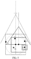
- the target discarding policy may be: as shown in FIG. 5 , when an identification characteristic of target T3 is less than the critical threshold, target T5 whose distance from the edge of the outer frame is less than or equal to a preset threshold and that has a minimum priority is deleted, and an outer frame is determined again, to ensure that the unmanned aerial vehicle can always relatively effectively track a target having a relatively high priority.
- a new outer frame of remaining targets is obtained by using the target discarding policy, to better obtain characteristics of the remaining targets, to ensure that the unmanned aerial vehicle can always relatively effectively track a target having a relatively high priority.
- the target discarding policy includes: S209: The unmanned aerial vehicle determines whether a priority of the target that cannot be identified is a lowest priority.
- the priority of the target may be obtained according to the method in S202.
- step S210 the unmanned aerial vehicle discards the target that cannot be identified and performs S213.
- step S211 the unmanned aerial vehicle further determines whether the priority of the target that cannot be identified is lower than a priority of a target whose distance from the edge of the outer frame is less than or equal to the preset threshold.
- step S210 the unmanned aerial vehicle performs step S210, to discard the target that cannot be identified, and performs step S213.
- step S212 that is, the unmanned aerial vehicle chooses to discard a target that has a lowest priority and that is of targets whose distances from the edge of the outer frame are less than or equal to the preset threshold, and perform step S213.
- the unmanned aerial vehicle regenerates an outer frame according to location information of remaining targets of the at least two targets, and enables the regenerated outer frame to fall within the vision angle range of the unmanned aerial vehicle.
- a vision angle center of the unmanned aerial vehicle always overlaps with the center of the outer frame.
- the unmanned aerial vehicle can be always located in a desirable location for capturing a target.
- the embodiments of the present invention further provide an unmanned aerial vehicle, including a processor and a computer readable storage medium, where the computer readable storage medium stores an instruction, and when the instruction is executed by the processor, any one of the foregoing target tracking methods is executed.
- the embodiments of the present invention further provide a computer readable storage medium, storing a computer program, where when the computer program is executed by a processor, steps of any one of the foregoing target tracking methods is executed.
- the embodiments of the present invention further provide an unmanned aerial vehicle 10.
- the unmanned aerial vehicle 10 includes an unmanned aerial vehicle body 11, an unmanned aerial vehicle arm 12 connected to the unmanned aerial vehicle body 11, a power apparatus 13 disposed on the unmanned aerial vehicle arm 12, a photographing apparatus 14 connected to the unmanned aerial vehicle body 11, and a processor 15 that is disposed in the unmanned aerial vehicle body 11 and that is in communication connection with the photographing apparatus 14.
- the unmanned aerial vehicle 10 includes four unmanned aerial vehicle arms 12. That is, in this embodiment, the unmanned aerial vehicle is a four-rotor unmanned aerial vehicle. In another possible embodiment, the unmanned aerial vehicle may also be a six-rotor unmanned aerial vehicle (six unmanned aerial vehicle arms) or an eight-rotor unmanned aerial vehicle (eight unmanned aerial vehicle arms).
- the power apparatus 13 usually includes a rotor disposed at the end of the unmanned aerial vehicle arm 12 and a propeller connected to a shaft of the rotor. The rotor drives the propeller to rotate to provide a lift force for the unmanned aerial vehicle 10.
- the photographing apparatus 14 is an on-board camera, and is configured to shoot a picture or a video.
- the processor includes a vision processor and a flight control processor; the vision processor is configured to:
- an embodiment of the present invention further provides a target tracking apparatus, including:
- the determining module is specifically configured to:
- the determining module is specifically configured to:
- the adjustment module is further configured to:
- the generation module is further configured to determine priorities of the at least two targets.
- the adjustment module is further configured to:
- the adjustment module is specifically configured to implement the target discarding policy in the following manner:
Landscapes
- Engineering & Computer Science (AREA)
- Physics & Mathematics (AREA)
- General Physics & Mathematics (AREA)
- Remote Sensing (AREA)
- Aviation & Aerospace Engineering (AREA)
- Radar, Positioning & Navigation (AREA)
- Automation & Control Theory (AREA)
- Multimedia (AREA)
- Theoretical Computer Science (AREA)
- Astronomy & Astrophysics (AREA)
- Control Of Position, Course, Altitude, Or Attitude Of Moving Bodies (AREA)
- Traffic Control Systems (AREA)
Abstract
Description
- The present invention relates to target tracking technologies, and in particular, to a target tracking method, an unmanned aerial vehicle, and a computer readable storage medium.
- Currently, intelligent tracking of an unmanned aerial vehicle (Unmanned Aerial Vehicle, UAV) is limited to a single-target mode. However, as methods such as deep learning and a multisource image fractal characteristic are developed and internal hardware of unmanned aerial vehicles is improved, multi-target tracking of a single unmanned aerial vehicle is also widely studied. According to this idea, multiple targets in a same scenario can be tracked in real time. Therefore, an implementation policy of an intelligent tracking method restricted by a motion status of a target needs to be considered. When multiple initialized targets move at different speeds in different directions, to track the multiple targets, a policy is needed to implement tracking for maximum duration. When a spatial range of the multiple targets is excessively large, and some targets need to be selectively discarded to ensure overall tracking performance, how to select some targets and when to discard the targets is also a problem that needs to be considered.
- Embodiments of the present invention provide a target tracking method, an unmanned aerial vehicle, and a computer readable storage medium, to track multiple targets with robustness.
- The embodiments of the present invention provide a target tracking method, including:
- determining, by an unmanned aerial vehicle, at least two targets that need to be tracked;
- generating, by the unmanned aerial vehicle, an outer frame according to location information of the at least two targets, where the at least two targets are located within the outer frame; and
- adjusting, by the unmanned aerial vehicle, a flight parameter of the unmanned aerial vehicle, so that the outer frame falls within a vision angle range of the unmanned aerial vehicle.
- In an embodiment of the present invention, the method further includes:
receiving, by the unmanned aerial vehicle, information that is entered by a user and that is sent by a controller, where the information that is entered by the user includes information of a target that the user chooses to track. - In an embodiment of the present invention, the determining, by an unmanned aerial vehicle, at least two targets that need to be tracked includes:
- determining, by the unmanned aerial vehicle, the target that the user chooses to track as a target that needs to be tracked by the unmanned aerial vehicle, where
- a quantity of targets that the unmanned aerial vehicle determines to track is less than or equal to a quantity of targets selected by the user.
- In an embodiment of the present invention, the determining, by an unmanned aerial vehicle, at least two targets that need to be tracked includes:
- receiving, by the unmanned aerial vehicle, a signal sent by each of the at least two targets; and
- determining, by the unmanned aerial vehicle according to the signal, the at least two targets that need to be tracked.
- In an embodiment of the present invention, the method further includes:
- determining, by the unmanned aerial vehicle, a minimum vision angle that is needed so that the outer frame falls within a line of sight range of the unmanned aerial vehicle at a current moment; and
- determining, by the unmanned aerial vehicle, whether the minimum vision angle is greater than a safe vision angle α'; and if yes, increasing, by the unmanned aerial vehicle, a flight height of the unmanned aerial vehicle until the minimum vision angle that is needed so that the outer frame falls within the line of sight range of the unmanned aerial vehicle is less than the safe vision angle α' after the flight height is increased, where:
α' = η × α max , α max is a maximum vision angle of the unmanned aerial vehicle, and η is a safety coefficient. - In an embodiment of the present invention, the method further includes:
- when the unmanned aerial vehicle increases the flight height of the unmanned aerial vehicle, determining whether the at least two targets include a target that cannotcannot be identified by the unmanned aerial vehicle; and
- if yes, discarding a target according to a target discarding policy, regenerating an outer frame according to location information of remaining targets of the at least two targets, and adjusting the flight parameter of the unmanned aerial vehicle, so that the regenerated outer frame falls within the vision angle range of the unmanned aerial vehicle.
- In an embodiment of the present invention, the target discarding policy includes:
determining whether a priority of the target that cannot be identified by the unmanned aerial vehicle is the lowest priority; and if yes, discarding the target that cannot be identified by the unmanned aerial vehicle. - In an embodiment of the present invention, the target discarding policy further includes:
if the priority of the target that cannot be identified by the unmanned aerial vehicle is not the lowest priority, determining whether the priority of the target that cannot be identified by the unmanned aerial vehicle is lower than a priority of a target whose distance from an edge of the outer frame is less than or equal to a preset threshold; and if yes, discarding the target that cannot be identified by the unmanned aerial vehicle. - In an embodiment of the present invention, the target discarding policy further includes:
if the priority of the target that cannot be identified by the unmanned aerial vehicle is not lower than the priority of the target whose distance from the edge of the outer frame is less than or equal to the preset threshold, discarding a target that has the lowest priority and that is of targets whose distances from the edge of the outer frame are less than or equal to the preset threshold. - In an embodiment of the present invention, the target that cannot be identified by the unmanned aerial vehicle is a target whose identification characteristic is less than a critical threshold of an object that can be identified by the unmanned aerial vehicle.
- In an embodiment of the present invention, the method further includes:
determining the critical threshold according to at least one of the following:
resolution of a camera installed on the unmanned aerial vehicle, an initialized image size, a target image characteristic matching method, or an image transmission information loss rate. - In an embodiment of the present invention, the method further includes:
determining, by the unmanned aerial vehicle, priorities of the at least two targets. - In an embodiment of the present invention, the method further includes:
- receiving, by the unmanned aerial vehicle, information that is entered by a user and that is sent by a controller, where the information that is entered by the user includes information of a target that the user chooses to track; and
- determining, by the unmanned aerial vehicle, the priorities of the at least two targets according to a sequence in which the user selects targets that need to be tracked.
- In an embodiment of the present invention, the adjusting, by the unmanned aerial vehicle, a flight parameter of the unmanned aerial vehicle includes:
adjusting, by the unmanned aerial vehicle, a location and/or a flight height of the unmanned aerial vehicle. - In an embodiment of the present invention, the outer frame always falls within the vision angle range of the unmanned aerial vehicle.
- In an embodiment of the present invention, the outer frame is a circle in which the at least two targets are located and that has a minimum radius.
- In an embodiment of the present invention, the outer frame is a circumscribed square of a minimum circle, and the minimum circle is a circle in which the at least two targets are located and that has a minimum radius.
- In an embodiment of the present invention, a vision angle center of the unmanned aerial vehicle overlaps with the center of the outer frame.
- The embodiments of the present invention further provide an unmanned aerial vehicle, including:
- an unmanned aerial vehicle body;
- an unmanned aerial vehicle arm connected to the unmanned aerial vehicle body;
- a power apparatus disposed on the unmanned aerial vehicle arm;
- a photographing apparatus, configured to shoot a picture or a video; and
- a processor in communication connection with the photographing apparatus, where the processor is configured to:
- determine the at least two targets that need to be tracked;
- generate the outer frame according to the location information of the at least two targets, where the at least two targets are located within the outer frame; and
- adjust a flight parameter of the unmanned aerial vehicle, so that the outer frame falls within a vision angle range of the unmanned aerial vehicle.
- In an embodiment of the present invention, the processor includes a vision processor and a flight control processor;
the vision processor is configured to: - determine the at least two targets that need to be tracked;
- generate the outer frame according to the location information of the at least two targets, where the at least two targets are located within the outer frame; and
- send an instruction used to adjust the flight parameter of the unmanned aerial vehicle to the flight control processor, so that the outer frame falls within the vision angle range of the unmanned aerial vehicle; and
- the flight control processor is configured to:
receive the instruction and adjust the flight parameter of the unmanned aerial vehicle. - In an embodiment of the present invention, the processor is further configured to:
receive information that is entered by a user and that is sent by a controller, where the information that is entered by the user includes information of a target that the user chooses to track. - In an embodiment of the present invention, the processor is further configured to:
- determine the target that the user chooses to track as a target that needs to be tracked by the unmanned aerial vehicle, where
- a quantity of determined targets that need to be tracked is less than or equal to a quantity of targets selected by the user.
- In an embodiment of the present invention, the processor is further configured to:
- receive, by the unmanned aerial vehicle, a signal sent by each of the at least two targets; and
- determine, by the unmanned aerial vehicle according to the signal, the at least two targets that need to be tracked.
- In an embodiment of the present invention, the processor is further configured to:
- determine a minimum vision angle that is needed so that the outer frame falls within a line of sight range of the unmanned aerial vehicle at a current moment; and
- determine whether the minimum vision angle is greater than a safe vision angle α'; and if yes, increasing, by the unmanned aerial vehicle, a flight height of the unmanned aerial vehicle until the minimum vision angle that is needed so that the outer frame falls within the line of sight range of the unmanned aerial vehicle is less than the safe vision angle α' after the flight height is increased, where:
α' = η × α max , α max is a maximum vision angle of the unmanned aerial vehicle, and η is a safety coefficient. - In an embodiment of the present invention, the processor is further configured to:
- when the unmanned aerial vehicle increases the flight height of the unmanned aerial vehicle, determine whether the at least two targets include a target that cannot be identified by the unmanned aerial vehicle; and
- if yes, discard a target according to a target discarding policy, regenerate an outer frame according to location information of remaining targets of the at least two targets, and adjust the flight parameter of the unmanned aerial vehicle, so that the regenerated outer frame falls within the vision angle range of the unmanned aerial vehicle.
- In an embodiment of the present invention, the target discarding policy includes:
determining whether a priority of the target that cannot be identified by the unmanned aerial vehicle is the lowest priority; and if yes, discarding the target that cannot be identified by the unmanned aerial vehicle. - In an embodiment of the present invention, the target discarding policy further includes:
if the priority of the target that cannot be identified by the unmanned aerial vehicle is not the lowest priority, determining whether the priority of the target that cannot be identified by the unmanned aerial vehicle is lower than a priority of a target whose distance from an edge of the outer frame is less than or equal to a preset threshold; and if yes, discarding the target that cannot be identified by the unmanned aerial vehicle. - In an embodiment of the present invention, the target discarding policy further includes:
if the priority of the target that cannot be identified by the unmanned aerial vehicle is not lower than the priority of the target whose distance from the edge of the outer frame is less than or equal to the preset threshold, discarding a target that has the lowest priority and that is of targets whose distances from the edge of the outer frame are less than or equal to the preset threshold. - In an embodiment of the present invention, the target that cannot be identified by the unmanned aerial vehicle is a target whose identification characteristic is less than a critical threshold of an object that can be identified by the unmanned aerial vehicle.
- In an embodiment of the present invention, the processor is further configured to:
determine the critical threshold according to at least one of the following:
resolution of a camera installed on the unmanned aerial vehicle, an initialized image size, a target image characteristic matching method, or an image transmission information loss rate. - In an embodiment of the present invention, the processor is further configured to:
determine priorities of the at least two targets. - In an embodiment of the present invention, the processor is further configured to:
- receive information that is entered by a user and that is sent by a controller, where the information that is entered by the user includes information of a target that the user chooses to track; and
- determine the priorities of the at least two targets according to a sequence in which the user selects targets that need to be tracked.
- In an embodiment of the present invention, the adjusting, by the unmanned aerial vehicle, a flight parameter of the unmanned aerial vehicle includes:
adjusting, by the unmanned aerial vehicle, a location and/or a flight height of the unmanned aerial vehicle. - In an embodiment of the present invention, the outer frame always falls within the vision angle range of the unmanned aerial vehicle.
- In an embodiment of the present invention, the outer frame is a circle in which the at least two targets are located and that has a minimum radius.
- In an embodiment of the present invention, the outer frame is a circumscribed square of a minimum circle, and the minimum circle is a circle in which the at least two targets are located and that has a minimum radius.
- In an embodiment of the present invention, a vision angle center of the unmanned aerial vehicle overlaps with the center of the outer frame.
- The embodiments of the present invention further provide an unmanned aerial vehicle, including a processor and a computer readable storage medium, where the computer readable storage medium stores an instruction, and when the instruction is executed by the processor, the foregoing target tracking method is executed.
- The embodiments of the present invention further provide a computer readable storage medium, storing a computer program, where when the computer program is executed by a processor, the foregoing target tracking method is executed.
- Compared with the prior art, the embodiments of the present invention include: determining, by an unmanned aerial vehicle, at least two targets that need to be tracked; generating, by the unmanned aerial vehicle, an outer frame according to location information of the at least two targets, where the at least two targets are all located within the outer frame; and adjusting, by the unmanned aerial vehicle, a flight parameter of the unmanned aerial vehicle, so that the outer frame falls within a vision angle range of the unmanned aerial vehicle. According to the solutions of the embodiments of the present invention, the unmanned aerial vehicle generates the outer frame according to the location information of the at least two targets, and the unmanned aerial vehicle adjusts the flight parameter of the unmanned aerial vehicle, so that the outer frame falls within the vision angle range of the unmanned aerial vehicle. In this way, multiple targets are converted to a "single target", to find an optimal location for observing all the multiple targets, and it is ensured that the multiple targets are tracked with robustness for maximum duration.
- In an optional solution, when the unmanned aerial vehicle increases the flight height of the unmanned aerial vehicle, the unmanned aerial vehicle determines whether the at least two targets include a target that cannot be identified by the unmanned aerial vehicle; and if yes, discards a target according to a target discarding policy, regenerates an outer frame according to location information of remaining targets of the at least two targets, and adjusts the flight parameter of the unmanned aerial vehicle, so that the regenerated outer frame falls within the vision angle range of the unmanned aerial vehicle. In this way, it is ensured that the unmanned aerial vehicle can always relatively effectively track a target having a relatively high priority.
- Other characteristics and advantages of the present invention are described below in the specification, and some characteristics and advantages of the present invention become obvious in the specification, or are known in implementation of the present invention. Objectives and other advantages of the present invention may be implemented and obtained according to structures particularly described in the specification, claims, and accompanying drawings.
- The accompanying drawings are intended to facilitate understanding of the technical solutions of the present invention, and are a part of the specification. The accompanying drawings are used to describe the technical solutions of the present invention together with the embodiments of this application, and constitute no limitation on the technical solutions of the present invention.
-
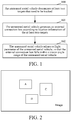
FIG. 1 is a flowchart of a first embodiment of a target tracking method according to the present invention; -
FIG. 2 is a schematic diagram of selecting multiple targets by a user according to the first embodiment of the present invention; -
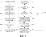
FIG. 3 is a flowchart of a second embodiment of a target tracking method according to the present invention; -
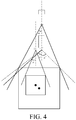
FIG. 4 is a schematic diagram of adjusting a flight parameter of an unmanned aerial vehicle by the unmanned aerial vehicle, so that an outer frame falls within a vision angle range of the unmanned aerial vehicle according to the second embodiment of the present invention; -
FIG. 5 is a simple principle diagram of a target discarding policy according to the present invention; -
FIG. 6 is a schematic structural diagram of an unmanned aerial vehicle according to an embodiment of the present invention; -
FIG. 7 is a schematic structural diagram of an unmanned aerial vehicle according to another embodiment of the present invention; and -
FIG. 8 is a simple structural diagram of a target tracking apparatus according to an embodiment of the present invention. - The following describes the embodiments of the present invention in detail with reference to the accompanying drawings. It should be noted that the embodiments of this application and characteristics of the embodiments may be randomly combined with each other provided that there is no conflict.
- Steps shown in flowcharts of the accompanying drawings may be performed, for example, in a computer system of a set of computer executable instructions. In addition, although a logical sequence is shown in a flowchart, the shown or described steps may be performed in a different sequence in some cases.
- Referring to
FIG. 1 , the first embodiment of the present invention provides a target tracking method. The method includes:
Step 100: An unmanned aerial vehicle determines at least two targets that need to be tracked. - The determining, by an unmanned aerial vehicle, at least two targets that need to be tracked may be: determining, by the unmanned aerial vehicle according to selection of a user on a control terminal, the targets that need to be tracked. As shown in
FIG. 2 , in an embodiment of the present invention, the user selects, by clicking or drawing a box on the control terminal, the at least two targets that need to be tracked, the control terminal sends a target tracking instruction to the unmanned aerial vehicle, and the unmanned aerial vehicle determines, according to the instruction, the at least two targets that need to be tracked. - In an embodiment of the present invention, a quantity of targets that the unmanned aerial vehicle determines to track is less than or equal to a quantity of targets selected by the user.
- Alternatively, the determining, by an unmanned aerial vehicle, at least two targets that need to be tracked may be: receiving, by the unmanned aerial vehicle, a tracking signal sent by each of the at least two targets; and determining, by the unmanned aerial vehicle according to the tracking signal, the at least two targets that need to be tracked. In other words, the unmanned aerial vehicle determines a target that sends a tracking signal as a target that needs to be tracked. The tracking signal includes at least location information of the target.
- Step 101: The unmanned aerial vehicle generates an outer frame according to location information of the at least two targets, where the at least two targets are located within the outer frame.
- The outer frame is an important tool used by the unmanned aerial vehicle to convert multi-target tracking to single-target tracking. The at least two targets that need to be tracked are box-selected in the outer frame, and the outer frame may be generated by the unmanned aerial vehicle, or may be generated by the control terminal after the user clicks or box-selects, on the control terminal, the at least two targets that need to be tracked. When the outer frame is generated by the unmanned aerial vehicle, the outer frame may be visible or invisible to the user on a side of the control terminal.
- Location information of a target may be location information of the target in an image coordinate system, or may be latitude and longitude information of the target. The image coordinate system is a coordinate system in an image shot by the unmanned aerial vehicle. Conversion between the location information in the image coordinate system and latitude and longitude information of the target may be performed according to a conversion relationship of the coordinate system. Specifically, coordinate system conversion may be performed by using a technology known by a person skilled in the art, and details are not described herein.
- In addition, alternatively, the unmanned aerial vehicle may determine location information of a target by using a target detection method, or determine location information of a target by using another technical means (for example, an intelligent tracking technology) known by a person skilled in the art. Details are not described herein.
- Step 102: The unmanned aerial vehicle adjusts a flight parameter of the unmanned aerial vehicle, so that the outer frame falls within a vision angle range of the unmanned aerial vehicle.
- After generating the outer frame and box-selecting all targets that need to be tracked, the unmanned aerial vehicle may adjust a location and/or a flight height of the unmanned aerial vehicle, so that the outer frame falls within the vision angle range of the unmanned aerial vehicle, to track the at least two targets.
- In an embodiment of the present invention, a vision angle center of the unmanned aerial vehicle always overlaps with the center of the outer frame. When the vision angle center of the unmanned aerial vehicle always overlaps with the center of the outer frame, the unmanned aerial vehicle can be always located in a desirable location for capturing a target.
- Referring to
FIG. 3 , the second embodiment of the present invention provides a target tracking method. The method includes:
S201: A user selects, on a controller, at least two targets that need to be tracked. - The user may select a target by clicking or drawing a box. When the user selects a target by clicking, the target selected by the user is displayed by displaying an area whose center is a point clicked by the user. When the user selects a target by drawing a box, the target selected by the user is displayed by displaying the box drawn by the user. As shown in
FIG. 2 , the user sequentially selects target A, target B, and target C by drawing a box, and the screen of the controller sequentially displays the three boxes drawn by the user. - S202: The unmanned aerial vehicle receives information that is sent by the controller and that is of the targets that the user chooses to track, and determines the targets that the user chooses to track as targets that need to be tracked.
- In an embodiment of the present invention, the information of the targets selected by the user includes location information of the selected targets. For example, the information of the targets selected by the user may be location information of the targets selected by the user in an image coordinate system, or may be latitude and longitude information of the targets selected by the user. Location information of a target in an image coordinate system may be coordinates of the target in the image coordinate system for a column number and a row number of the target in an image.
- In another possible embodiment, the information of the targets selected by the user may also include information about a sequence in which the targets are selected, and the unmanned aerial vehicle may determine priorities of the at least two targets according to the information about the sequence in which the targets are selected by the user. For example, the controller determines the priorities of the selected targets according to the sequence in which the targets are selected by the user, and sends both a priority of each target and location information of the target to the unmanned aerial vehicle. The controller may determine that a priority of a target first selected by the user is higher than a priority of a target subsequently selected by the user, or determine that a priority of a target first selected by the user is lower than a priority of a target subsequently selected by the user, or determine the priorities of the targets in another manner. This is not limited in the embodiments of the present invention. For example, in
FIG. 2 , the user sequentially selects target A, target B, and target C, a priority of target A is higher than a priority of target B, and the priority of target B is higher than a priority of target C. - The priorities of the targets may also be obtained by using a policy pre-stored in the unmanned aerial vehicle, and when the priorities of the targets are needed, the unmanned aerial vehicle obtains the priorities of the targets according to the policy.
- S203: The unmanned aerial vehicle generates an outer frame according to location information of the at least two targets, where the at least two targets are located within the outer frame. The outer frame is an important tool used by the unmanned aerial vehicle to convert multi-target tracking to single-target tracking. The at least two targets that need to be tracked are box-selected in the outer frame, and the outer frame may be generated by the unmanned aerial vehicle, or may be generated by the control terminal after the user clicks or box-selects, on the control terminal, the at least two targets that need to be tracked. When the outer frame is generated by the unmanned aerial vehicle, the outer frame may be visible or invisible to the user on a side of the control terminal.
- Location information of a target may be location information of the target in an image coordinate system, or may be latitude and longitude information of the target. The image coordinate system is a coordinate system in an image shot by the unmanned aerial vehicle. Conversion between the location information in the image coordinate system and latitude and longitude information of the target may be performed according to a conversion relationship of the coordinate system. Specifically, coordinate system conversion may be performed by using a technology known by a person skilled in the art, and details are not described herein.
- In addition, alternatively, the unmanned aerial vehicle may determine location information of a target by using a target detection method, or determine location information of a target by using another technical means (for example, an intelligent tracking technology) known by a person skilled in the art. Details are not described herein.
- In an embodiment of the present invention, the outer frame is a circle in which the at least two targets are located and that has a minimum radius. The circle that has the minimum radius may be determined by using a minimum circle algorithm as follows:
- the unmanned aerial vehicle selects any three targets;
- the unmanned aerial vehicle determines, according to location information of the selected three targets, that a minimum circle including the selected three targets is a circumscribed circle of the selected three targets, or a minimum circle including the selected three targets is a circle, where two of the selected three targets are located at two ends of the diameter of the circle, and the remaining target is located inside the circle;
- the unmanned aerial vehicle determines whether a target that is farthest from the center of the determined minimum circle and that is of targets other than the selected three targets is located inside the minimum circle or on the circumference of the minimum circle. If the target is located inside the minimum circle or on the circumference of the minimum circle, the minimum circle is the minimum circle that is searched for; and
- if the target is located outside the minimum circle, continue to perform the step of selecting three new targets.
- At least one of the three new targets is not selected previously.
- In another possible embodiment, the outer frame including multiple targets may also be a circumscribed square of the determined minimum circle. In addition, the outer frame may be determined in another manner.
- As the outer frame including the at least two targets is determined by using a minimum circle algorithm, the unmanned aerial vehicle can obtain an optimal vision angle range, a calculation speed is high, and a resource of the unmanned aerial vehicle is not occupied.
- In another embodiment of the present invention, the outer frame is also a circumscribed square of the minimum circle. In addition, the outer frame may be determined in another manner, and this is not limited in the present invention.
- S204: The unmanned aerial vehicle determines a minimum vision angle that is needed so that the outer frame falls within a line of sight range of the unmanned aerial vehicle at a current moment.
- As shown in
FIG. 4 , the unmanned aerial vehicle may obtain, according to a formula
- α" is the minimum vision angle, L is the radius or half the side length of the outer frame, and H is the height of the unmanned aerial vehicle.
- S205: The unmanned aerial vehicle determines whether the minimum vision angle α" is greater than a safe vision angle α'.
- α'=η×α_max, α_max is the maximum vision angle of the unmanned aerial vehicle, η is a safety coefficient, η is an empirical value, and η may be generally from 0.7 to 0.9.
- When the unmanned aerial vehicle tracks multiple targets, there may be a case in which the tracked targets separately move in different directions. When the height of the unmanned aerial vehicle does not change, an imaging size of the outer frame constructed by using the foregoing method becomes increasingly large in an image. As shown in
FIG. 4 , in this case, a projection location of the unmanned aerial vehicle needs to be adjusted, and in addition, it needs to be ensured that the minimum vision angle α" of the unmanned aerial vehicle is always less than the safe vision angle α'. - It is ensured that the minimum vision angle α" is always less than the safe vision angle α', so that the outer frame including multiple targets can always fall within the vision angle range of the unmanned aerial vehicle, multiple targets can fall within the vision angle range of the unmanned aerial vehicle to the highest extent, and target loss can be avoided.
- S206: If the minimum vision angle α" is less than or equal to the safe vision angle α', the unmanned aerial vehicle adjusts a flight parameter of the unmanned aerial vehicle, so that the outer frame falls within the vision angle range of the unmanned aerial vehicle. In an embodiment of the present invention, the flight parameter includes a location and/or a flight height of the unmanned aerial vehicle.
- The unmanned aerial vehicle may adjust the flight parameter of the unmanned aerial vehicle, so that the determined outer frame falls within the vision angle range of the unmanned aerial vehicle, to track the at least two targets.
- S207: If the minimum vision angle α" is greater than the safe vision angle α', the unmanned aerial vehicle needs to increase the flight height of the unmanned aerial vehicle until the minimum vision angle α" is less than or equal to the safe vision angle α'.
- S208: The unmanned aerial vehicle determines whether the at least two targets include a target that cannot be identified.
- Because factors such as resolution of a camera installed on the unmanned aerial vehicle and image transmission constitute a limitation, when the size of the outer frame gradually increases, the unmanned aerial vehicle cannot constantly resolve a problem of full-target capturing and tracking by increasing the height of the unmanned aerial vehicle. In the embodiments of the present invention, the concept of a critical threshold λ is provided. The critical threshold is related to resolution r of a camera, an initialized image size s, a target image characteristic matching method f, an image transmission information loss rate d, and the like. That is, λ = λ(r, s, f, d...). The resolution of a camera refers to a description measurement that fineness of details of a bitmap image depends on, and is indicated by a quantity of pixels. The initialized image size refers to a size of a target in an image during initialization, and is generally indicated by a circumscribed rectangular box. The target image characteristic matching method is a method used to find target prospect during tracking. The image transmission information loss rate refers to that actual image information losses by a particular percentage because of interference during image transmission.
- The critical threshold may be provided according to experience. An identification characteristic that depends on the critical threshold and that is of a target in an image cannot be less than a critical threshold of an object that the unmanned aerial vehicle can identify, and if the identification characteristic is less than the critical threshold, the unmanned aerial vehicle determines the target as a target that cannot be identified.
- For example, it is assumed that resolution of a camera installed on the unmanned aerial vehicle is 1280×720, an initialized target size is 200×100, and an average image transmission information loss rate is 10% . To ensure target tracking precision and robustness, assuming that a current quantity of pixels that describes a target characteristic and that depends on the critical threshold cannot be less than 2000, a minimum imaging size of a target is 64×34. Once the size of the target in a target group is less than 64×34, the unmanned aerial vehicle starts a target discarding policy.
- The target discarding policy may be: as shown in
FIG. 5 , when an identification characteristic of target T3 is less than the critical threshold, target T5 whose distance from the edge of the outer frame is less than or equal to a preset threshold and that has a minimum priority is deleted, and an outer frame is determined again, to ensure that the unmanned aerial vehicle can always relatively effectively track a target having a relatively high priority. - A new outer frame of remaining targets is obtained by using the target discarding policy, to better obtain characteristics of the remaining targets, to ensure that the unmanned aerial vehicle can always relatively effectively track a target having a relatively high priority.
- In an embodiment of the present invention, the target discarding policy includes:
S209: The unmanned aerial vehicle determines whether a priority of the target that cannot be identified is a lowest priority. The priority of the target may be obtained according to the method in S202. - If yes, the unmanned aerial vehicle performs step S210, that is, the unmanned aerial vehicle discards the target that cannot be identified and performs S213.
- If not, the unmanned aerial vehicle performs step S211, that is, the unmanned aerial vehicle further determines whether the priority of the target that cannot be identified is lower than a priority of a target whose distance from the edge of the outer frame is less than or equal to the preset threshold.
- If yes, the unmanned aerial vehicle performs step S210, to discard the target that cannot be identified, and performs step S213.
- If not, perform step S212, that is, the unmanned aerial vehicle chooses to discard a target that has a lowest priority and that is of targets whose distances from the edge of the outer frame are less than or equal to the preset threshold, and perform step S213.
- S213: The unmanned aerial vehicle regenerates an outer frame according to location information of remaining targets of the at least two targets, and enables the regenerated outer frame to fall within the vision angle range of the unmanned aerial vehicle.
- In an embodiment of the present invention, a vision angle center of the unmanned aerial vehicle always overlaps with the center of the outer frame. When the vision angle center of the unmanned aerial vehicle always overlaps with the center of the outer frame, the unmanned aerial vehicle can be always located in a desirable location for capturing a target.
- Referring to
FIG. 6 , the embodiments of the present invention further provide an unmanned aerial vehicle, including a processor and a computer readable storage medium, where the computer readable storage medium stores an instruction, and when the instruction is executed by the processor, any one of the foregoing target tracking methods is executed. - The embodiments of the present invention further provide a computer readable storage medium, storing a computer program, where when the computer program is executed by a processor, steps of any one of the foregoing target tracking methods is executed.
- Referring to
FIG. 7 , the embodiments of the present invention further provide an unmannedaerial vehicle 10. The unmannedaerial vehicle 10 includes an unmannedaerial vehicle body 11, an unmannedaerial vehicle arm 12 connected to the unmannedaerial vehicle body 11, apower apparatus 13 disposed on the unmannedaerial vehicle arm 12, a photographingapparatus 14 connected to the unmannedaerial vehicle body 11, and aprocessor 15 that is disposed in the unmannedaerial vehicle body 11 and that is in communication connection with the photographingapparatus 14. - In this embodiment, the unmanned
aerial vehicle 10 includes four unmannedaerial vehicle arms 12. That is, in this embodiment, the unmanned aerial vehicle is a four-rotor unmanned aerial vehicle. In another possible embodiment, the unmanned aerial vehicle may also be a six-rotor unmanned aerial vehicle (six unmanned aerial vehicle arms) or an eight-rotor unmanned aerial vehicle (eight unmanned aerial vehicle arms). Thepower apparatus 13 usually includes a rotor disposed at the end of the unmannedaerial vehicle arm 12 and a propeller connected to a shaft of the rotor. The rotor drives the propeller to rotate to provide a lift force for the unmannedaerial vehicle 10. The photographingapparatus 14 is an on-board camera, and is configured to shoot a picture or a video. - In an embodiment of the present invention, the processor includes a vision processor and a flight control processor;
the vision processor is configured to: - determine the at least two targets that need to be tracked;
- generate the outer frame according to the location information of the at least two targets, where the at least two targets are located within the outer frame; and
- send an instruction used to adjust the flight parameter of the unmanned aerial vehicle to the flight control processor, so that the outer frame falls within the vision angle range of the unmanned aerial vehicle; and
- the flight control processor is configured to receive the instruction sent by the vision processor, adjust the flight parameter of the unmanned aerial vehicle, and execute the foregoing target tracking method.
- Referring to
FIG. 8 , an embodiment of the present invention further provides a target tracking apparatus, including: - a determining module, configured to determine the at least two targets that need to be tracked;
- a generation module, configured to generate the outer frame according to the location information of the at least two targets, where the at least two targets are located within the outer frame or on the outer frame; and
- an adjustment module, configured to adjust the flight parameter of the unmanned aerial vehicle, so that the outer frame falls within the vision angle range of the unmanned aerial vehicle.
- Optionally, the determining module is specifically configured to:
- determine the target selected the user as a target that needs to be tracked by the unmanned aerial vehicle, where
- a quantity of targets that the unmanned aerial vehicle determines to track is less than or equal to a quantity of targets selected by the user.
- Optionally, the determining module is specifically configured to:
- receive a signal sent by each of the at least two targets; and
- determine, according to the signal, the at least two targets that need to be tracked.
- Optionally, the adjustment module is further configured to:
- determine a minimum vision angle that is needed so that the outer frame falls within a line of sight range of the unmanned aerial vehicle at a current moment; and
- determine whether the minimum vision angle is greater than a safe vision angle α'; and if yes, increasing, by the unmanned aerial vehicle, a flight height of the unmanned aerial vehicle until the minimum vision angle that is needed so that the outer frame falls within the line of sight range of the unmanned aerial vehicle is less than the safe vision angle α' after the flight height is increased, where:
- α' = η × α max , α max is a maximum vision angle of the unmanned aerial vehicle, and η is a safety coefficient.
- Optionally, the generation module is further configured to determine priorities of the at least two targets.
- The adjustment module is further configured to:
- when the unmanned aerial vehicle increases the flight height of the unmanned aerial vehicle, determine whether the at least two targets include a target that cannot be identified by the unmanned aerial vehicle; and
- if yes, discard a target according to a target discarding policy, regenerate an outer frame according to location information of remaining targets of the at least two targets, and adjust the flight parameter of the unmanned aerial vehicle, so that the regenerated outer frame falls within the vision angle range of the unmanned aerial vehicle.
- Optionally, the adjustment module is specifically configured to implement the target discarding policy in the following manner:
- determining whether a priority of the target that cannot be identified by the unmanned aerial vehicle is the lowest priority; and if yes, discarding the target that cannot be identified by the unmanned aerial vehicle;
- if the priority of the target that cannot be identified by the unmanned aerial vehicle is not the lowest priority, determining whether the priority of the target that cannot be identified by the unmanned aerial vehicle is lower than a priority of a target whose distance from an edge of the outer frame is less than or equal to a preset threshold; and if yes, discarding the target that cannot be identified by the unmanned aerial vehicle; and
- if the priority of the target that cannot be identified by the unmanned aerial vehicle is not lower than the priority of the target whose distance from the edge of the outer frame is less than or equal to the preset threshold, discarding a target that has the lowest priority and that is of targets whose distances from the edge of the outer frame are less than or equal to the preset threshold. In the embodiments of the present invention, the determining module, the generation module, and the adjustment module may be disposed in a flight control chip or a processor in the unmanned aerial vehicle.
- Although implementations of the present invention are disclosed above, the foregoing content is only intended to facilitate understanding of implementations used in the present invention, instead of limiting the present invention. Any person skilled in the art of the present invention may make any change or modification to forms or details of implementations without departing from the spirit and scope disclosed in the present invention, but the patent protection scope of the present invention still needs to be subject to the appended claims.
Claims (39)
- A target tracking method, comprising:determining, by an unmanned aerial vehicle, at least two targets that need to be tracked;generating, by the unmanned aerial vehicle, an outer frame according to location information of the at least two targets, wherein the at least two targets are located within the outer frame; andadjusting, by the unmanned aerial vehicle, a flight parameter of the unmanned aerial vehicle, so that the outer frame falls within a vision angle range of the unmanned aerial vehicle.
- The target tracking method according to claim 1, wherein the method further comprises:
receiving, by the unmanned aerial vehicle, information that is entered by a user and that is sent by a controller, wherein the information that is entered by the user comprises information of a target that the user chooses to track. - The target tracking method according to claim 1, wherein the determining, by an unmanned aerial vehicle, at least two targets that need to be tracked comprises:determining, by the unmanned aerial vehicle, the target that the user chooses to track as a target that needs to be tracked by the unmanned aerial vehicle, whereina quantity of targets that the unmanned aerial vehicle determines to track is less than or equal to a quantity of targets selected by the user.
- The target tracking method according to claim 1, wherein the determining, by an unmanned aerial vehicle, at least two targets that need to be tracked comprises:receiving, by the unmanned aerial vehicle, a signal sent by each of the at least two targets; anddetermining, by the unmanned aerial vehicle according to the signal, the at least two targets that need to be tracked.
- The target tracking method according to any one of claims 1 to 4, wherein the method further comprises:determining, by the unmanned aerial vehicle, a minimum vision angle that is needed so that the outer frame falls within a line of sight range of the unmanned aerial vehicle at a current moment; anddetermining, by the unmanned aerial vehicle, whether the minimum vision angle is greater than a safe vision angle α'; and if yes, increasing, by the unmanned aerial vehicle, a flight height of the unmanned aerial vehicle until the minimum vision angle that is needed so that the outer frame falls within the line of sight range of the unmanned aerial vehicle is less than the safe vision angle α' after the flight height is increased, wherein:
α' = η × α max , α max is a maximum vision angle of the unmanned aerial vehicle, and η is a safety coefficient. - The target tracking method according to claim 5, wherein the method further comprises:when the unmanned aerial vehicle increases the flight height of the unmanned aerial vehicle, determining whether the at least two targets comprise a target that cannot be identified by the unmanned aerial vehicle; andif yes, discarding a target according to a target discarding policy, regenerating an outer frame according to location information of remaining targets of the at least two targets, and adjusting the flight parameter of the unmanned aerial vehicle, so that the regenerated outer frame falls within the vision angle range of the unmanned aerial vehicle.
- The target tracking method according to claim 6, wherein the target discarding policy comprises:
determining whether a priority of the target that cannot be identified by the unmanned aerial vehicle is the lowest priority; and if yes, discarding the target that cannot be identified by the unmanned aerial vehicle. - The target tracking method according to claim 7, wherein the target discarding policy further comprises:
if the priority of the target that cannot be identified by the unmanned aerial vehicle is not the lowest priority, determining whether the priority of the target that cannot be identified by the unmanned aerial vehicle is lower than a priority of a target whose distance from an edge of the outer frame is less than or equal to a preset threshold; and if yes, discarding the target that cannot be identified by the unmanned aerial vehicle. - The target tracking method according to claim 8, wherein the target discarding policy further comprises:
if the priority of the target that cannot be identified by the unmanned aerial vehicle is not lower than the priority of the target whose distance from the edge of the outer frame is less than or equal to the preset threshold, discarding a target that has the lowest priority and that is of targets whose distances from the edge of the outer frame are less than or equal to the preset threshold. - The target tracking method according to any one of claims 7 to 9, wherein the target that cannot be identified by the unmanned aerial vehicle is a target whose identification characteristic is less than a critical threshold of an object that can be identified by the unmanned aerial vehicle.
- The target tracking method according to claim 10, wherein the method further comprises:
determining the critical threshold according to at least one of the following:
resolution of a camera installed on the unmanned aerial vehicle, an initialized image size, a target image characteristic matching method, or an image transmission information loss rate. - The target tracking method according to any one of claims 7 to 11, wherein the method further comprises:
determining, by the unmanned aerial vehicle, priorities of the at least two targets. - The target tracking method according to any one of claims 7 to 11, wherein the method further comprises:receiving, by the unmanned aerial vehicle, information that is entered by a user and that is sent by a controller, wherein the information that is entered by the user comprises information of a target that the user chooses to track; anddetermining, by the unmanned aerial vehicle, the priorities of the at least two targets according to a sequence in which the user selects targets that need to be tracked.
- The target tracking method according to any one of claims 1 to 13, wherein the adjusting, by the unmanned aerial vehicle, a flight parameter of the unmanned aerial vehicle comprises:
adjusting, by the unmanned aerial vehicle, a location and/or a flight height of the unmanned aerial vehicle. - The target tracking method according to any one of claims 1 to 14, wherein the outer frame always falls within the vision angle range of the unmanned aerial vehicle.
- The target tracking method according to any one of claims 1 to 15, wherein the outer frame is a circle in which the at least two targets are located and that has a minimum radius.
- The target tracking method according to any one of claims 1 to 15, wherein the outer frame is a circumscribed square of a minimum circle, and the minimum circle is a circle in which the at least two targets are located and that has a minimum radius.
- The target tracking method according to any one of claims 1 to 17, wherein a vision angle center of the unmanned aerial vehicle overlaps with the center of the outer frame.
- An unmanned aerial vehicle, comprising:an unmanned aerial vehicle body;an unmanned aerial vehicle arm connected to the unmanned aerial vehicle body;a power apparatus disposed on the unmanned aerial vehicle arm;a photographing apparatus, configured to shoot a picture or a video; anda processor in communication connection with the photographing apparatus, wherein the processor is configured to:determine at least two targets that need to be tracked;generate an outer frame according to location information of the at least two targets, wherein the at least two targets are located within the outer frame; andadjust a flight parameter of the unmanned aerial vehicle, so that the outer frame falls within a vision angle range of the unmanned aerial vehicle.
- The unmanned aerial vehicle according to claim 19, wherein the processor comprises a vision processor and a flight control processor;
the vision processor is configured to:determine the at least two targets that need to be tracked;generate the outer frame according to the location information of the at least two targets, wherein the at least two targets are located within the outer frame; andsend an instruction used to adjust the flight parameter of the unmanned aerial vehicle to the flight control processor, so that the outer frame falls within the vision angle range of the unmanned aerial vehicle; andthe flight control processor is configured to:
receive the instruction and adjust the flight parameter of the unmanned aerial vehicle. - The unmanned aerial vehicle according to claim 19 or 20, wherein the processor is further configured to:
receive information that is entered by a user and that is sent by a controller, wherein the information that is entered by the user comprises information of a target that the user chooses to track. - The unmanned aerial vehicle according to claim 19 or 20, wherein the processor is further configured to:determine the target that the user chooses to track as a target that needs to be tracked by the unmanned aerial vehicle, whereina quantity of determined targets that need to be tracked is less than or equal to a quantity of targets selected by the user.
- The unmanned aerial vehicle according to claim 19 or 20, wherein the processor is further configured to:receive a signal sent by each of the at least two targets; anddetermine, according to the signal, the at least two targets that need to be tracked.
- The unmanned aerial vehicle according to any one of claims 19 to 23, wherein the processor is further configured to:determine a minimum vision angle that is needed so that the outer frame falls within a line of sight range of the unmanned aerial vehicle at a current moment; anddetermine whether the minimum vision angle is greater than a safe vision angle α'; and if yes, increasing, by the unmanned aerial vehicle, a flight height of the unmanned aerial vehicle until the minimum vision angle that is needed so that the outer frame falls within the line of sight range of the unmanned aerial vehicle is less than the safe vision angle α' after the flight height is increased, wherein:α' = η × α max , α max is a maximum vision angle of the unmanned aerial vehicle, and η is a safety coefficient.
- The unmanned aerial vehicle according to claim 24, wherein the processor is further configured to:when the unmanned aerial vehicle increases the flight height of the unmanned aerial vehicle, determine whether the at least two targets comprise a target that cannot be identified by the unmanned aerial vehicle; andif yes, discard a target according to a target discarding policy, regenerate an outer frame according to location information of remaining targets of the at least two targets, and adjust the flight parameter of the unmanned aerial vehicle, so that the regenerated outer frame falls within the vision angle range of the unmanned aerial vehicle.
- The unmanned aerial vehicle according to claim 25, wherein the target discarding policy comprises:
determining whether a priority of the target that cannot be identified by the unmanned aerial vehicle is the lowest priority; and if yes, discarding the target that cannot be identified by the unmanned aerial vehicle. - The unmanned aerial vehicle according to claim 26, wherein the target discarding policy further comprises:
if the priority of the target that cannot be identified by the unmanned aerial vehicle is not the lowest priority, determine whether the priority of the target that cannot be identified by the unmanned aerial vehicle is lower than a priority of a target whose distance from an edge of the outer frame is less than or equal to a preset threshold; and if yes, discard the target that cannot be identified by the unmanned aerial vehicle. - The unmanned aerial vehicle according to claim 27, wherein the target discarding policy further comprises:
if the priority of the target that cannot be identified by the unmanned aerial vehicle is not lower than the priority of the target whose distance from the edge of the outer frame is less than or equal to the preset threshold, discarding a target that has the lowest priority and that is of targets whose distances from the edge of the outer frame are less than or equal to the preset threshold. - The unmanned aerial vehicle according to any one of claims 26 to 28, wherein the target that cannot be identified by the unmanned aerial vehicle is a target whose identification characteristic is less than a critical threshold of an object that can be identified by the unmanned aerial vehicle.
- The unmanned aerial vehicle according to claim 29, wherein the processor is further configured to:
determine the critical threshold according to at least one of the following:
resolution of a camera installed on the unmanned aerial vehicle, an initialized image size, a target image characteristic matching method, or an image transmission information loss rate. - The unmanned aerial vehicle according to any one of claims 26 to 30, wherein the processor is further configured to:
determine priorities of the at least two targets. - The unmanned aerial vehicle according to any one of claims 26 to 30, wherein the processor is further configured to:receive information that is entered by a user and that is sent by a controller, wherein the information that is entered by the user comprises information of a target that the user chooses to track; anddetermine the priorities of the at least two targets according to a sequence in which the user selects targets that need to be tracked.
- The unmanned aerial vehicle according to any one of claims 19 to 32, wherein the adjusting, by the unmanned aerial vehicle, a flight parameter of the unmanned aerial vehicle comprises:
adjusting, by the unmanned aerial vehicle, a location and/or a flight height of the unmanned aerial vehicle. - The unmanned aerial vehicle according to any one of claims 19 to 33, wherein the outer frame always falls within the vision angle range of the unmanned aerial vehicle.
- The unmanned aerial vehicle according to any one of claims 19 to 34, wherein the outer frame is a circle in which the at least two targets are located and that has a minimum radius.
- The unmanned aerial vehicle according to any one of claims 19 to 34, wherein the outer frame is a circumscribed square of a minimum circle, and the minimum circle is a circle in which the at least two targets are located and that has a minimum radius.
- The unmanned aerial vehicle according to any one of claims 19 to 36, wherein a vision angle center of the unmanned aerial vehicle overlaps with the center of the outer frame.
- An unmanned aerial vehicle, comprising a processor and a computer readable storage medium, wherein the computer readable storage medium stores an instruction, and when the instruction is executed by the processor, the method according to any one of claims 1 to 18 is executed.
- A computer readable storage medium, storing a computer program, wherein when the computer program is executed by a processor, the method according to any one of claims 1 to 18 is executed.
Applications Claiming Priority (2)
| Application Number | Priority Date | Filing Date | Title |
|---|---|---|---|
| CN201710756805.2A CN107505951B (en) | 2017-08-29 | 2017-08-29 | Target tracking method, unmanned aerial vehicle and computer readable storage medium |
| PCT/CN2017/108983 WO2019041534A1 (en) | 2017-08-29 | 2017-11-01 | Target tracking method, unmanned aerial vehicle and computer-readable storage medium |
Publications (3)
| Publication Number | Publication Date |
|---|---|
| EP3474111A1 true EP3474111A1 (en) | 2019-04-24 |
| EP3474111A4 EP3474111A4 (en) | 2019-09-25 |
| EP3474111B1 EP3474111B1 (en) | 2023-03-29 |
Family
ID=60693215
Family Applications (1)
| Application Number | Title | Priority Date | Filing Date |
|---|---|---|---|
| EP17814293.1A Active EP3474111B1 (en) | 2017-08-29 | 2017-11-01 | Target tracking method by an unmanned aerial vehicle |
Country Status (4)
| Country | Link |
|---|---|
| US (1) | US10719087B2 (en) |
| EP (1) | EP3474111B1 (en) |
| CN (1) | CN107505951B (en) |
| WO (1) | WO2019041534A1 (en) |
Cited By (1)
| Publication number | Priority date | Publication date | Assignee | Title |
|---|---|---|---|---|
| CN113296540A (en) * | 2021-05-20 | 2021-08-24 | 北京航空航天大学 | Hybrid intelligent following and obstacle avoiding method suitable for indoor unmanned aerial vehicle |
Families Citing this family (16)
| Publication number | Priority date | Publication date | Assignee | Title |
|---|---|---|---|---|
| CN108163203B (en) * | 2017-12-31 | 2020-10-13 | 深圳市道通智能航空技术有限公司 | Shooting control method and device and aircraft |
| WO2019140699A1 (en) | 2018-01-22 | 2019-07-25 | SZ DJI Technology Co., Ltd. | Methods and system for multi-target tracking |
| WO2019140686A1 (en) * | 2018-01-22 | 2019-07-25 | 深圳市大疆创新科技有限公司 | Following control method, control terminal, and unmanned aerial vehicle |
| CN108919640B (en) * | 2018-04-20 | 2020-04-03 | 西北工业大学 | Implementation method of UAV adaptive multi-target tracking |
| CN108549413A (en) * | 2018-04-27 | 2018-09-18 | 全球能源互联网研究院有限公司 | A kind of holder method of controlling rotation, device and unmanned vehicle |
| CN109683473B (en) * | 2018-10-26 | 2021-12-24 | 中国飞行试验研究院 | Comprehensive man-machine closed-loop system modeling and verifying method |
| CN109583347A (en) * | 2018-11-22 | 2019-04-05 | 华南理工大学 | A method of it is tracked for a long time for mobile platform |
| CN109684429B (en) * | 2018-12-18 | 2022-06-21 | 南京云灿信息科技有限公司 | Low-altitude flight target identification system and algorithm based on three-dimensional digital earth |
| WO2020170534A1 (en) * | 2019-02-18 | 2020-08-27 | ソニー株式会社 | Flying object, information processing method, and program |
| CN110348460B (en) * | 2019-07-04 | 2021-10-22 | 成都旷视金智科技有限公司 | An angle-based target detection training method, target detection method and device |
| WO2021217450A1 (en) * | 2020-04-28 | 2021-11-04 | 深圳市大疆创新科技有限公司 | Target tracking method and device, and storage medium |
| JP7371578B2 (en) * | 2020-07-01 | 2023-10-31 | トヨタ自動車株式会社 | Information processing device and information processing method |
| CN113870310A (en) * | 2021-09-27 | 2021-12-31 | 深圳市道通智能航空技术股份有限公司 | A target tracking method, device and storage medium based on UAV |
| WO2023137758A1 (en) * | 2022-01-24 | 2023-07-27 | 深圳市大疆创新科技有限公司 | Control method for movable platform, head-mounted device, system, and storage medium |
| WO2025203271A1 (en) * | 2024-03-26 | 2025-10-02 | 本田技研工業株式会社 | Mobile body control device, mobile body control method, and program |
| CN118466518A (en) * | 2024-07-09 | 2024-08-09 | 天津云圣智能科技有限责任公司 | Method, device and computer storage medium for drone aerial photography of photographed objects |
Family Cites Families (16)
| Publication number | Priority date | Publication date | Assignee | Title |
|---|---|---|---|---|
| CN100565244C (en) * | 2007-10-31 | 2009-12-02 | 北京航空航天大学 | Multi-mode multi-target precision tracking device and method |
| WO2010077389A2 (en) * | 2008-08-05 | 2010-07-08 | University Of Florida Research Foundation, Inc. | Systems and methods for maintaining multiple objects within a camera field-of-view |
| TWI388205B (en) * | 2008-12-19 | 2013-03-01 | Ind Tech Res Inst | Method and apparatus for tracking objects |
| CN101969548B (en) * | 2010-10-15 | 2012-05-23 | 中国人民解放军国防科学技术大学 | Active video acquisition method and device based on binocular camera |
| TW201249713A (en) * | 2011-06-02 | 2012-12-16 | Hon Hai Prec Ind Co Ltd | Unmanned aerial vehicle control system and method |
| US9293831B1 (en) * | 2012-04-20 | 2016-03-22 | L-3 Communications Corp. | Directional single-axis horn-reflector antenna |
| CN104200488A (en) * | 2014-08-04 | 2014-12-10 | 合肥工业大学 | Multi-target tracking method based on graph representation and matching |
| CN104732559B (en) * | 2015-02-02 | 2017-08-01 | 大连民族学院 | A kind of multi-target detection and tracking method based on RGB D data |
| EP3347789B1 (en) * | 2015-09-11 | 2021-08-04 | SZ DJI Technology Co., Ltd. | Systems and methods for detecting and tracking movable objects |
| CN107209854A (en) * | 2015-09-15 | 2017-09-26 | 深圳市大疆创新科技有限公司 | Systems and methods for supporting smooth object following |
| CN105847684A (en) * | 2016-03-31 | 2016-08-10 | 深圳奥比中光科技有限公司 | Unmanned aerial vehicle |
| CN105957105B (en) * | 2016-04-22 | 2018-10-02 | 清华大学 | The multi-object tracking method and system of Behavior-based control study |
| CN106161953A (en) * | 2016-08-12 | 2016-11-23 | 零度智控(北京)智能科技有限公司 | A kind of track up method and apparatus |
| CN106709456B (en) * | 2016-12-27 | 2020-03-31 | 成都通甲优博科技有限责任公司 | Unmanned aerial vehicle target tracking frame initialization method based on computer vision |
| CN106909172A (en) * | 2017-03-06 | 2017-06-30 | 重庆零度智控智能科技有限公司 | Around tracking, device and unmanned plane |
| CN106981073B (en) * | 2017-03-31 | 2019-08-06 | 中南大学 | A method and system for real-time tracking of ground moving targets based on UAV |
-
2017
- 2017-08-29 CN CN201710756805.2A patent/CN107505951B/en active Active
- 2017-11-01 EP EP17814293.1A patent/EP3474111B1/en active Active
- 2017-11-01 WO PCT/CN2017/108983 patent/WO2019041534A1/en not_active Ceased
- 2017-12-20 US US15/848,979 patent/US10719087B2/en active Active
Cited By (2)
| Publication number | Priority date | Publication date | Assignee | Title |
|---|---|---|---|---|
| CN113296540A (en) * | 2021-05-20 | 2021-08-24 | 北京航空航天大学 | Hybrid intelligent following and obstacle avoiding method suitable for indoor unmanned aerial vehicle |
| CN113296540B (en) * | 2021-05-20 | 2022-07-12 | 北京航空航天大学 | A hybrid intelligent following and obstacle avoidance method suitable for indoor drones |
Also Published As
| Publication number | Publication date |
|---|---|
| CN107505951B (en) | 2020-08-21 |
| WO2019041534A1 (en) | 2019-03-07 |
| EP3474111B1 (en) | 2023-03-29 |
| US20190064852A1 (en) | 2019-02-28 |
| CN107505951A (en) | 2017-12-22 |
| EP3474111A4 (en) | 2019-09-25 |
| US10719087B2 (en) | 2020-07-21 |
Similar Documents
| Publication | Publication Date | Title |
|---|---|---|
| US10719087B2 (en) | Target tracking method, unmanned aerial vehicle, and computer readable storage medium | |
| EP3690727B1 (en) | Learning method and learning device for sensor fusion to integrate information acquired by radar capable of distance estimation and information acquired by camera to thereby improve neural network for supporting autonomous driving, and testing method and testing device using the same | |
| US9632509B1 (en) | Operating a UAV with a narrow obstacle-sensor field-of-view | |
| CN108508916B (en) | Control method, device and equipment for unmanned aerial vehicle formation and storage medium | |
| CN111326023A (en) | Method, device, equipment and storage medium for UAV route early warning | |
| US20190278303A1 (en) | Method of controlling obstacle avoidance for unmanned aerial vehicle and unmanned aerial vehicle | |
| CN109101957A (en) | Binocular solid data processing method, device, intelligent driving equipment and storage medium | |
| CN112985398A (en) | Target positioning method and system | |
| CN109118532A (en) | Vision depth of field estimation method, device, equipment and storage medium | |
| CN110751336A (en) | Obstacle avoidance method and obstacle avoidance device of unmanned carrier and unmanned carrier | |
| CN107450586B (en) | Method and system for adjusting air route and unmanned aerial vehicle system | |
| CN106845491A (en) | Automatic correction method based on unmanned plane under a kind of parking lot scene | |
| CN111444786A (en) | Crowd evacuation method, device and system based on unmanned aerial vehicle group and storage medium | |
| CN120406516B (en) | Obstacle avoidance methods, storage media, mission units, and drone systems for unmanned aerial vehicles (UAVs) | |
| WO2020237422A1 (en) | Aerial surveying method, aircraft and storage medium | |
| CN108163203A (en) | A kind of filming control method, device and aircraft | |
| CN110187720A (en) | Unmanned plane guidance method, device, system, medium and electronic equipment | |
| WO2023197841A1 (en) | Focusing method, photographic apparatus, unmanned aerial vehicle, and storage medium | |
| CN111712827A (en) | Method, device and system for adjusting observation field, storage medium and mobile device | |
| WO2021238743A1 (en) | Flight control method and apparatus for unmanned aerial vehicle, and unmanned aerial vehicle | |
| CN110009595A (en) | A kind of image processing method, device, picture processing chip and aircraft | |
| US20210011490A1 (en) | Flight control method, device, and machine-readable storage medium | |
| CN115951716A (en) | An adaptive grouping method for fixed-wing unmanned aerial vehicles using monocular visual information | |
| US20160358523A1 (en) | Display control methods and apparatuses | |
| CN117274835A (en) | A monocular 3D object detection method, system, medium and terminal for drones |
Legal Events
| Date | Code | Title | Description |
|---|---|---|---|
| STAA | Information on the status of an ep patent application or granted ep patent |
Free format text: STATUS: UNKNOWN |
|
| STAA | Information on the status of an ep patent application or granted ep patent |
Free format text: STATUS: THE INTERNATIONAL PUBLICATION HAS BEEN MADE |
|
| PUAI | Public reference made under article 153(3) epc to a published international application that has entered the european phase |
Free format text: ORIGINAL CODE: 0009012 |
|
| STAA | Information on the status of an ep patent application or granted ep patent |
Free format text: STATUS: REQUEST FOR EXAMINATION WAS MADE |
|
| 17P | Request for examination filed |
Effective date: 20171228 |
|
| AK | Designated contracting states |
Kind code of ref document: A1 Designated state(s): AL AT BE BG CH CY CZ DE DK EE ES FI FR GB GR HR HU IE IS IT LI LT LU LV MC MK MT NL NO PL PT RO RS SE SI SK SM TR |
|
| AX | Request for extension of the european patent |
Extension state: BA ME |
|
| RIN1 | Information on inventor provided before grant (corrected) |
Inventor name: ZHANG, KE Inventor name: ZANG, BO |
|
| REG | Reference to a national code |
Ref country code: DE Ref legal event code: R079 Ref document number: 602017067248 Country of ref document: DE Free format text: PREVIOUS MAIN CLASS: G05D0001120000 Ipc: G05D0001000000 |
|
| A4 | Supplementary search report drawn up and despatched |
Effective date: 20190827 |
|
| RIC1 | Information provided on ipc code assigned before grant |
Ipc: G05D 1/00 20060101AFI20190821BHEP |
|
| STAA | Information on the status of an ep patent application or granted ep patent |
Free format text: STATUS: EXAMINATION IS IN PROGRESS |
|
| 17Q | First examination report despatched |
Effective date: 20201022 |
|
| DAV | Request for validation of the european patent (deleted) | ||
| DAX | Request for extension of the european patent (deleted) | ||
| GRAP | Despatch of communication of intention to grant a patent |
Free format text: ORIGINAL CODE: EPIDOSNIGR1 |
|
| STAA | Information on the status of an ep patent application or granted ep patent |
Free format text: STATUS: GRANT OF PATENT IS INTENDED |
|
| INTG | Intention to grant announced |
Effective date: 20221020 |
|
| GRAS | Grant fee paid |
Free format text: ORIGINAL CODE: EPIDOSNIGR3 |
|
| GRAA | (expected) grant |
Free format text: ORIGINAL CODE: 0009210 |
|
| STAA | Information on the status of an ep patent application or granted ep patent |
Free format text: STATUS: THE PATENT HAS BEEN GRANTED |
|
| AK | Designated contracting states |
Kind code of ref document: B1 Designated state(s): AL AT BE BG CH CY CZ DE DK EE ES FI FR GB GR HR HU IE IS IT LI LT LU LV MC MK MT NL NO PL PT RO RS SE SI SK SM TR |
|
| REG | Reference to a national code |
Ref country code: CH Ref legal event code: EP |
|
| REG | Reference to a national code |
Ref country code: DE Ref legal event code: R096 Ref document number: 602017067248 Country of ref document: DE |
|
| REG | Reference to a national code |
Ref country code: AT Ref legal event code: REF Ref document number: 1557130 Country of ref document: AT Kind code of ref document: T Effective date: 20230415 |
|
| REG | Reference to a national code |
Ref country code: IE Ref legal event code: FG4D |
|
| REG | Reference to a national code |
Ref country code: LT Ref legal event code: MG9D |
|
| PG25 | Lapsed in a contracting state [announced via postgrant information from national office to epo] |
Ref country code: RS Free format text: LAPSE BECAUSE OF FAILURE TO SUBMIT A TRANSLATION OF THE DESCRIPTION OR TO PAY THE FEE WITHIN THE PRESCRIBED TIME-LIMIT Effective date: 20230329 Ref country code: NO Free format text: LAPSE BECAUSE OF FAILURE TO SUBMIT A TRANSLATION OF THE DESCRIPTION OR TO PAY THE FEE WITHIN THE PRESCRIBED TIME-LIMIT Effective date: 20230629 Ref country code: LV Free format text: LAPSE BECAUSE OF FAILURE TO SUBMIT A TRANSLATION OF THE DESCRIPTION OR TO PAY THE FEE WITHIN THE PRESCRIBED TIME-LIMIT Effective date: 20230329 Ref country code: LT Free format text: LAPSE BECAUSE OF FAILURE TO SUBMIT A TRANSLATION OF THE DESCRIPTION OR TO PAY THE FEE WITHIN THE PRESCRIBED TIME-LIMIT Effective date: 20230329 Ref country code: HR Free format text: LAPSE BECAUSE OF FAILURE TO SUBMIT A TRANSLATION OF THE DESCRIPTION OR TO PAY THE FEE WITHIN THE PRESCRIBED TIME-LIMIT Effective date: 20230329 |
|
| REG | Reference to a national code |
Ref country code: NL Ref legal event code: MP Effective date: 20230329 |
|
| REG | Reference to a national code |
Ref country code: AT Ref legal event code: MK05 Ref document number: 1557130 Country of ref document: AT Kind code of ref document: T Effective date: 20230329 |
|
| PG25 | Lapsed in a contracting state [announced via postgrant information from national office to epo] |
Ref country code: SE Free format text: LAPSE BECAUSE OF FAILURE TO SUBMIT A TRANSLATION OF THE DESCRIPTION OR TO PAY THE FEE WITHIN THE PRESCRIBED TIME-LIMIT Effective date: 20230329 Ref country code: NL Free format text: LAPSE BECAUSE OF FAILURE TO SUBMIT A TRANSLATION OF THE DESCRIPTION OR TO PAY THE FEE WITHIN THE PRESCRIBED TIME-LIMIT Effective date: 20230329 Ref country code: GR Free format text: LAPSE BECAUSE OF FAILURE TO SUBMIT A TRANSLATION OF THE DESCRIPTION OR TO PAY THE FEE WITHIN THE PRESCRIBED TIME-LIMIT Effective date: 20230630 Ref country code: FI Free format text: LAPSE BECAUSE OF FAILURE TO SUBMIT A TRANSLATION OF THE DESCRIPTION OR TO PAY THE FEE WITHIN THE PRESCRIBED TIME-LIMIT Effective date: 20230329 |
|
| PG25 | Lapsed in a contracting state [announced via postgrant information from national office to epo] |
Ref country code: SM Free format text: LAPSE BECAUSE OF FAILURE TO SUBMIT A TRANSLATION OF THE DESCRIPTION OR TO PAY THE FEE WITHIN THE PRESCRIBED TIME-LIMIT Effective date: 20230329 Ref country code: RO Free format text: LAPSE BECAUSE OF FAILURE TO SUBMIT A TRANSLATION OF THE DESCRIPTION OR TO PAY THE FEE WITHIN THE PRESCRIBED TIME-LIMIT Effective date: 20230329 Ref country code: PT Free format text: LAPSE BECAUSE OF FAILURE TO SUBMIT A TRANSLATION OF THE DESCRIPTION OR TO PAY THE FEE WITHIN THE PRESCRIBED TIME-LIMIT Effective date: 20230731 Ref country code: ES Free format text: LAPSE BECAUSE OF FAILURE TO SUBMIT A TRANSLATION OF THE DESCRIPTION OR TO PAY THE FEE WITHIN THE PRESCRIBED TIME-LIMIT Effective date: 20230329 Ref country code: EE Free format text: LAPSE BECAUSE OF FAILURE TO SUBMIT A TRANSLATION OF THE DESCRIPTION OR TO PAY THE FEE WITHIN THE PRESCRIBED TIME-LIMIT Effective date: 20230329 Ref country code: AT Free format text: LAPSE BECAUSE OF FAILURE TO SUBMIT A TRANSLATION OF THE DESCRIPTION OR TO PAY THE FEE WITHIN THE PRESCRIBED TIME-LIMIT Effective date: 20230329 |
|
| PG25 | Lapsed in a contracting state [announced via postgrant information from national office to epo] |
Ref country code: SK Free format text: LAPSE BECAUSE OF FAILURE TO SUBMIT A TRANSLATION OF THE DESCRIPTION OR TO PAY THE FEE WITHIN THE PRESCRIBED TIME-LIMIT Effective date: 20230329 Ref country code: PL Free format text: LAPSE BECAUSE OF FAILURE TO SUBMIT A TRANSLATION OF THE DESCRIPTION OR TO PAY THE FEE WITHIN THE PRESCRIBED TIME-LIMIT Effective date: 20230329 Ref country code: IS Free format text: LAPSE BECAUSE OF FAILURE TO SUBMIT A TRANSLATION OF THE DESCRIPTION OR TO PAY THE FEE WITHIN THE PRESCRIBED TIME-LIMIT Effective date: 20230729 |
|
| REG | Reference to a national code |
Ref country code: DE Ref legal event code: R097 Ref document number: 602017067248 Country of ref document: DE |
|
| PGFP | Annual fee paid to national office [announced via postgrant information from national office to epo] |
Ref country code: GB Payment date: 20231123 Year of fee payment: 7 |
|
| PG25 | Lapsed in a contracting state [announced via postgrant information from national office to epo] |
Ref country code: DK Free format text: LAPSE BECAUSE OF FAILURE TO SUBMIT A TRANSLATION OF THE DESCRIPTION OR TO PAY THE FEE WITHIN THE PRESCRIBED TIME-LIMIT Effective date: 20230329 Ref country code: CZ Free format text: LAPSE BECAUSE OF FAILURE TO SUBMIT A TRANSLATION OF THE DESCRIPTION OR TO PAY THE FEE WITHIN THE PRESCRIBED TIME-LIMIT Effective date: 20230329 |
|
| PLBE | No opposition filed within time limit |
Free format text: ORIGINAL CODE: 0009261 |
|
| STAA | Information on the status of an ep patent application or granted ep patent |
Free format text: STATUS: NO OPPOSITION FILED WITHIN TIME LIMIT |
|
| 26N | No opposition filed |
Effective date: 20240103 |
|
| PG25 | Lapsed in a contracting state [announced via postgrant information from national office to epo] |
Ref country code: SI Free format text: LAPSE BECAUSE OF FAILURE TO SUBMIT A TRANSLATION OF THE DESCRIPTION OR TO PAY THE FEE WITHIN THE PRESCRIBED TIME-LIMIT Effective date: 20230329 |
|
| PG25 | Lapsed in a contracting state [announced via postgrant information from national office to epo] |
Ref country code: SI Free format text: LAPSE BECAUSE OF FAILURE TO SUBMIT A TRANSLATION OF THE DESCRIPTION OR TO PAY THE FEE WITHIN THE PRESCRIBED TIME-LIMIT Effective date: 20230329 Ref country code: IT Free format text: LAPSE BECAUSE OF FAILURE TO SUBMIT A TRANSLATION OF THE DESCRIPTION OR TO PAY THE FEE WITHIN THE PRESCRIBED TIME-LIMIT Effective date: 20230329 |
|
| REG | Reference to a national code |
Ref country code: CH Ref legal event code: PL |
|
| PG25 | Lapsed in a contracting state [announced via postgrant information from national office to epo] |
Ref country code: MC Free format text: LAPSE BECAUSE OF FAILURE TO SUBMIT A TRANSLATION OF THE DESCRIPTION OR TO PAY THE FEE WITHIN THE PRESCRIBED TIME-LIMIT Effective date: 20230329 |
|
| PG25 | Lapsed in a contracting state [announced via postgrant information from national office to epo] |
Ref country code: LU Free format text: LAPSE BECAUSE OF NON-PAYMENT OF DUE FEES Effective date: 20231101 |
|
| PG25 | Lapsed in a contracting state [announced via postgrant information from national office to epo] |
Ref country code: CH Free format text: LAPSE BECAUSE OF NON-PAYMENT OF DUE FEES Effective date: 20231130 |
|
| PG25 | Lapsed in a contracting state [announced via postgrant information from national office to epo] |
Ref country code: MC Free format text: LAPSE BECAUSE OF FAILURE TO SUBMIT A TRANSLATION OF THE DESCRIPTION OR TO PAY THE FEE WITHIN THE PRESCRIBED TIME-LIMIT Effective date: 20230329 Ref country code: LU Free format text: LAPSE BECAUSE OF NON-PAYMENT OF DUE FEES Effective date: 20231101 Ref country code: CH Free format text: LAPSE BECAUSE OF NON-PAYMENT OF DUE FEES Effective date: 20231130 |
|
| REG | Reference to a national code |
Ref country code: BE Ref legal event code: MM Effective date: 20231130 |
|
| REG | Reference to a national code |
Ref country code: IE Ref legal event code: MM4A |
|
| PG25 | Lapsed in a contracting state [announced via postgrant information from national office to epo] |
Ref country code: IE Free format text: LAPSE BECAUSE OF NON-PAYMENT OF DUE FEES Effective date: 20231101 |
|
| PG25 | Lapsed in a contracting state [announced via postgrant information from national office to epo] |
Ref country code: BE Free format text: LAPSE BECAUSE OF NON-PAYMENT OF DUE FEES Effective date: 20231130 |
|
| PG25 | Lapsed in a contracting state [announced via postgrant information from national office to epo] |
Ref country code: IE Free format text: LAPSE BECAUSE OF NON-PAYMENT OF DUE FEES Effective date: 20231101 Ref country code: BE Free format text: LAPSE BECAUSE OF NON-PAYMENT OF DUE FEES Effective date: 20231130 |
|
| PG25 | Lapsed in a contracting state [announced via postgrant information from national office to epo] |
Ref country code: BG Free format text: LAPSE BECAUSE OF FAILURE TO SUBMIT A TRANSLATION OF THE DESCRIPTION OR TO PAY THE FEE WITHIN THE PRESCRIBED TIME-LIMIT Effective date: 20230329 |
|
| PG25 | Lapsed in a contracting state [announced via postgrant information from national office to epo] |
Ref country code: BG Free format text: LAPSE BECAUSE OF FAILURE TO SUBMIT A TRANSLATION OF THE DESCRIPTION OR TO PAY THE FEE WITHIN THE PRESCRIBED TIME-LIMIT Effective date: 20230329 |
|
| GBPC | Gb: european patent ceased through non-payment of renewal fee |
Effective date: 20241101 |
|
| PG25 | Lapsed in a contracting state [announced via postgrant information from national office to epo] |
Ref country code: CY Free format text: LAPSE BECAUSE OF FAILURE TO SUBMIT A TRANSLATION OF THE DESCRIPTION OR TO PAY THE FEE WITHIN THE PRESCRIBED TIME-LIMIT; INVALID AB INITIO Effective date: 20171101 |
|
| PG25 | Lapsed in a contracting state [announced via postgrant information from national office to epo] |
Ref country code: HU Free format text: LAPSE BECAUSE OF FAILURE TO SUBMIT A TRANSLATION OF THE DESCRIPTION OR TO PAY THE FEE WITHIN THE PRESCRIBED TIME-LIMIT; INVALID AB INITIO Effective date: 20171101 |
|
| PG25 | Lapsed in a contracting state [announced via postgrant information from national office to epo] |
Ref country code: GB Free format text: LAPSE BECAUSE OF NON-PAYMENT OF DUE FEES Effective date: 20241101 |
|
| PG25 | Lapsed in a contracting state [announced via postgrant information from national office to epo] |
Ref country code: TR Free format text: LAPSE BECAUSE OF FAILURE TO SUBMIT A TRANSLATION OF THE DESCRIPTION OR TO PAY THE FEE WITHIN THE PRESCRIBED TIME-LIMIT Effective date: 20230329 |
|
| PGFP | Annual fee paid to national office [announced via postgrant information from national office to epo] |
Ref country code: DE Payment date: 20251119 Year of fee payment: 9 |
|
| PGFP | Annual fee paid to national office [announced via postgrant information from national office to epo] |
Ref country code: FR Payment date: 20251126 Year of fee payment: 9 |