EP3474040A2 - Lidar device with heated cover useful for automated vehicles - Google Patents
Lidar device with heated cover useful for automated vehicles Download PDFInfo
- Publication number
- EP3474040A2 EP3474040A2 EP18197223.3A EP18197223A EP3474040A2 EP 3474040 A2 EP3474040 A2 EP 3474040A2 EP 18197223 A EP18197223 A EP 18197223A EP 3474040 A2 EP3474040 A2 EP 3474040A2
- Authority
- EP
- European Patent Office
- Prior art keywords
- radiation
- type
- cover
- reflecting surfaces
- detector device
- Prior art date
- Legal status (The legal status is an assumption and is not a legal conclusion. Google has not performed a legal analysis and makes no representation as to the accuracy of the status listed.)
- Granted
Links
Images

Classifications
-
- B—PERFORMING OPERATIONS; TRANSPORTING
- B60—VEHICLES IN GENERAL
- B60S—SERVICING, CLEANING, REPAIRING, SUPPORTING, LIFTING, OR MANOEUVRING OF VEHICLES, NOT OTHERWISE PROVIDED FOR
- B60S1/00—Cleaning of vehicles
- B60S1/02—Cleaning windscreens, windows or optical devices
- B60S1/023—Cleaning windscreens, windows or optical devices including defroster or demisting means
-
- G—PHYSICS
- G01—MEASURING; TESTING
- G01S—RADIO DIRECTION-FINDING; RADIO NAVIGATION; DETERMINING DISTANCE OR VELOCITY BY USE OF RADIO WAVES; LOCATING OR PRESENCE-DETECTING BY USE OF THE REFLECTION OR RERADIATION OF RADIO WAVES; ANALOGOUS ARRANGEMENTS USING OTHER WAVES
- G01S7/00—Details of systems according to groups G01S13/00, G01S15/00, G01S17/00
- G01S7/48—Details of systems according to groups G01S13/00, G01S15/00, G01S17/00 of systems according to group G01S17/00
- G01S7/481—Constructional features, e.g. arrangements of optical elements
-
- B—PERFORMING OPERATIONS; TRANSPORTING
- B60—VEHICLES IN GENERAL
- B60Q—ARRANGEMENT OF SIGNALLING OR LIGHTING DEVICES, THE MOUNTING OR SUPPORTING THEREOF OR CIRCUITS THEREFOR, FOR VEHICLES IN GENERAL
- B60Q1/00—Arrangement of optical signalling or lighting devices, the mounting or supporting thereof or circuits therefor
- B60Q1/0017—Devices integrating an element dedicated to another function
- B60Q1/0023—Devices integrating an element dedicated to another function the element being a sensor, e.g. distance sensor, camera
-
- G—PHYSICS
- G01—MEASURING; TESTING
- G01S—RADIO DIRECTION-FINDING; RADIO NAVIGATION; DETERMINING DISTANCE OR VELOCITY BY USE OF RADIO WAVES; LOCATING OR PRESENCE-DETECTING BY USE OF THE REFLECTION OR RERADIATION OF RADIO WAVES; ANALOGOUS ARRANGEMENTS USING OTHER WAVES
- G01S13/00—Systems using the reflection or reradiation of radio waves, e.g. radar systems; Analogous systems using reflection or reradiation of waves whose nature or wavelength is irrelevant or unspecified
- G01S13/88—Radar or analogous systems specially adapted for specific applications
- G01S13/93—Radar or analogous systems specially adapted for specific applications for anti-collision purposes
- G01S13/931—Radar or analogous systems specially adapted for specific applications for anti-collision purposes of land vehicles
-
- G—PHYSICS
- G01—MEASURING; TESTING
- G01S—RADIO DIRECTION-FINDING; RADIO NAVIGATION; DETERMINING DISTANCE OR VELOCITY BY USE OF RADIO WAVES; LOCATING OR PRESENCE-DETECTING BY USE OF THE REFLECTION OR RERADIATION OF RADIO WAVES; ANALOGOUS ARRANGEMENTS USING OTHER WAVES
- G01S17/00—Systems using the reflection or reradiation of electromagnetic waves other than radio waves, e.g. lidar systems
- G01S17/88—Lidar systems specially adapted for specific applications
- G01S17/93—Lidar systems specially adapted for specific applications for anti-collision purposes
- G01S17/931—Lidar systems specially adapted for specific applications for anti-collision purposes of land vehicles
-
- G—PHYSICS
- G01—MEASURING; TESTING
- G01S—RADIO DIRECTION-FINDING; RADIO NAVIGATION; DETERMINING DISTANCE OR VELOCITY BY USE OF RADIO WAVES; LOCATING OR PRESENCE-DETECTING BY USE OF THE REFLECTION OR RERADIATION OF RADIO WAVES; ANALOGOUS ARRANGEMENTS USING OTHER WAVES
- G01S7/00—Details of systems according to groups G01S13/00, G01S15/00, G01S17/00
- G01S7/48—Details of systems according to groups G01S13/00, G01S15/00, G01S17/00 of systems according to group G01S17/00
- G01S7/481—Constructional features, e.g. arrangements of optical elements
- G01S7/4811—Constructional features, e.g. arrangements of optical elements common to transmitter and receiver
- G01S7/4813—Housing arrangements
-
- G—PHYSICS
- G02—OPTICS
- G02B—OPTICAL ELEMENTS, SYSTEMS OR APPARATUS
- G02B27/00—Optical systems or apparatus not provided for by any of the groups G02B1/00 - G02B26/00, G02B30/00
- G02B27/0006—Optical systems or apparatus not provided for by any of the groups G02B1/00 - G02B26/00, G02B30/00 with means to keep optical surfaces clean, e.g. by preventing or removing dirt, stains, contamination, condensation
-
- B—PERFORMING OPERATIONS; TRANSPORTING
- B32—LAYERED PRODUCTS
- B32B—LAYERED PRODUCTS, i.e. PRODUCTS BUILT-UP OF STRATA OF FLAT OR NON-FLAT, e.g. CELLULAR OR HONEYCOMB, FORM
- B32B2307/00—Properties of the layers or laminate
- B32B2307/40—Properties of the layers or laminate having particular optical properties
- B32B2307/41—Opaque
-
- B—PERFORMING OPERATIONS; TRANSPORTING
- B32—LAYERED PRODUCTS
- B32B—LAYERED PRODUCTS, i.e. PRODUCTS BUILT-UP OF STRATA OF FLAT OR NON-FLAT, e.g. CELLULAR OR HONEYCOMB, FORM
- B32B2307/00—Properties of the layers or laminate
- B32B2307/40—Properties of the layers or laminate having particular optical properties
- B32B2307/412—Transparent
-
- B—PERFORMING OPERATIONS; TRANSPORTING
- B32—LAYERED PRODUCTS
- B32B—LAYERED PRODUCTS, i.e. PRODUCTS BUILT-UP OF STRATA OF FLAT OR NON-FLAT, e.g. CELLULAR OR HONEYCOMB, FORM
- B32B2307/00—Properties of the layers or laminate
- B32B2307/40—Properties of the layers or laminate having particular optical properties
- B32B2307/416—Reflective
-
- B—PERFORMING OPERATIONS; TRANSPORTING
- B32—LAYERED PRODUCTS
- B32B—LAYERED PRODUCTS, i.e. PRODUCTS BUILT-UP OF STRATA OF FLAT OR NON-FLAT, e.g. CELLULAR OR HONEYCOMB, FORM
- B32B33/00—Layered products characterised by particular properties or particular surface features, e.g. particular surface coatings; Layered products designed for particular purposes not covered by another single class
-
- B—PERFORMING OPERATIONS; TRANSPORTING
- B60—VEHICLES IN GENERAL
- B60S—SERVICING, CLEANING, REPAIRING, SUPPORTING, LIFTING, OR MANOEUVRING OF VEHICLES, NOT OTHERWISE PROVIDED FOR
- B60S1/00—Cleaning of vehicles
- B60S1/02—Cleaning windscreens, windows or optical devices
- B60S1/56—Cleaning windscreens, windows or optical devices specially adapted for cleaning other parts or devices than front windows or windscreens
-
- G—PHYSICS
- G01—MEASURING; TESTING
- G01S—RADIO DIRECTION-FINDING; RADIO NAVIGATION; DETERMINING DISTANCE OR VELOCITY BY USE OF RADIO WAVES; LOCATING OR PRESENCE-DETECTING BY USE OF THE REFLECTION OR RERADIATION OF RADIO WAVES; ANALOGOUS ARRANGEMENTS USING OTHER WAVES
- G01S7/00—Details of systems according to groups G01S13/00, G01S15/00, G01S17/00
- G01S7/48—Details of systems according to groups G01S13/00, G01S15/00, G01S17/00 of systems according to group G01S17/00
- G01S7/497—Means for monitoring or calibrating
- G01S2007/4975—Means for monitoring or calibrating of sensor obstruction by, e.g. dirt- or ice-coating, e.g. by reflection measurement on front-screen
- G01S2007/4977—Means for monitoring or calibrating of sensor obstruction by, e.g. dirt- or ice-coating, e.g. by reflection measurement on front-screen including means to prevent or remove the obstruction
-
- G—PHYSICS
- G01—MEASURING; TESTING
- G01S—RADIO DIRECTION-FINDING; RADIO NAVIGATION; DETERMINING DISTANCE OR VELOCITY BY USE OF RADIO WAVES; LOCATING OR PRESENCE-DETECTING BY USE OF THE REFLECTION OR RERADIATION OF RADIO WAVES; ANALOGOUS ARRANGEMENTS USING OTHER WAVES
- G01S13/00—Systems using the reflection or reradiation of radio waves, e.g. radar systems; Analogous systems using reflection or reradiation of waves whose nature or wavelength is irrelevant or unspecified
- G01S13/88—Radar or analogous systems specially adapted for specific applications
- G01S13/93—Radar or analogous systems specially adapted for specific applications for anti-collision purposes
- G01S13/931—Radar or analogous systems specially adapted for specific applications for anti-collision purposes of land vehicles
- G01S2013/9327—Sensor installation details
- G01S2013/93277—Sensor installation details in the lights
-
- G—PHYSICS
- G01—MEASURING; TESTING
- G01S—RADIO DIRECTION-FINDING; RADIO NAVIGATION; DETERMINING DISTANCE OR VELOCITY BY USE OF RADIO WAVES; LOCATING OR PRESENCE-DETECTING BY USE OF THE REFLECTION OR RERADIATION OF RADIO WAVES; ANALOGOUS ARRANGEMENTS USING OTHER WAVES
- G01S7/00—Details of systems according to groups G01S13/00, G01S15/00, G01S17/00
- G01S7/02—Details of systems according to groups G01S13/00, G01S15/00, G01S17/00 of systems according to group G01S13/00
- G01S7/027—Constructional details of housings, e.g. form, type, material or ruggedness
-
- G—PHYSICS
- G01—MEASURING; TESTING
- G01S—RADIO DIRECTION-FINDING; RADIO NAVIGATION; DETERMINING DISTANCE OR VELOCITY BY USE OF RADIO WAVES; LOCATING OR PRESENCE-DETECTING BY USE OF THE REFLECTION OR RERADIATION OF RADIO WAVES; ANALOGOUS ARRANGEMENTS USING OTHER WAVES
- G01S7/00—Details of systems according to groups G01S13/00, G01S15/00, G01S17/00
- G01S7/02—Details of systems according to groups G01S13/00, G01S15/00, G01S17/00 of systems according to group G01S13/00
- G01S7/40—Means for monitoring or calibrating
- G01S7/4004—Means for monitoring or calibrating of parts of a radar system
- G01S7/4039—Means for monitoring or calibrating of parts of a radar system of sensor or antenna obstruction, e.g. dirt- or ice-coating
- G01S7/4043—Means for monitoring or calibrating of parts of a radar system of sensor or antenna obstruction, e.g. dirt- or ice-coating including means to prevent or remove the obstruction
- G01S7/4047—Heated dielectric lens, e.g. by heated wire
-
- H—ELECTRICITY
- H05—ELECTRIC TECHNIQUES NOT OTHERWISE PROVIDED FOR
- H05B—ELECTRIC HEATING; ELECTRIC LIGHT SOURCES NOT OTHERWISE PROVIDED FOR; CIRCUIT ARRANGEMENTS FOR ELECTRIC LIGHT SOURCES, IN GENERAL
- H05B1/00—Details of electric heating devices
- H05B1/02—Automatic switching arrangements specially adapted to apparatus ; Control of heating devices
- H05B1/0227—Applications
- H05B1/023—Industrial applications
- H05B1/0236—Industrial applications for vehicles
-
- H—ELECTRICITY
- H05—ELECTRIC TECHNIQUES NOT OTHERWISE PROVIDED FOR
- H05B—ELECTRIC HEATING; ELECTRIC LIGHT SOURCES NOT OTHERWISE PROVIDED FOR; CIRCUIT ARRANGEMENTS FOR ELECTRIC LIGHT SOURCES, IN GENERAL
- H05B6/00—Heating by electric, magnetic or electromagnetic fields
- H05B6/64—Heating using microwaves
- H05B6/647—Aspects related to microwave heating combined with other heating techniques
- H05B6/6482—Aspects related to microwave heating combined with other heating techniques combined with radiant heating, e.g. infrared heating
Definitions
- Sensors for such systems may incorporate LIDAR (light detection and ranging) or RADAR for detecting an object or another vehicle in the pathway of or otherwise near the vehicle.
- LIDAR light detection and ranging
- RADAR RADAR
- Environmental conditions may be limiting on the availability or effectiveness of such sensing technologies. For example, in colder climates it is possible for ice or condensation to form or collect on the sensor window or casing. In those cases, the LIDAR transmission, reception or both may be compromised or even blocked entirely.
- known heating technologies to prevent ice build-up tend to introduce additional complications or interfere with proper LIDAR sensor operation.
- known heating circuits or coatings for windows or other surfaces interfere with or block LIDAR transmission through the window and, therefore, are not useful with LIDAR sensors.
- Other known options include separate heaters but those introduce other complications, such as providing a mounting location and wiring to power and control the heater.
- An illustrative example embodiment of a detector device includes a sensor portion that is configured to at least emit or receive a first type of radiation.
- a cover near the sensor portion is transparent to the first type of radiation to allow the first type of radiation to pass through the cover.
- a radiation source emits a second, different type of radiation into the cover.
- a plurality of reflecting surfaces are transparent to the first type of radiation and at least partially opaque to the second type of radiation to at least partially reflect the second type of radiation into the cover to increase a temperature of at least a portion of the cover.
- the first type of radiation may comprise LIDAR radiation.
- the second type of radiation may comprise infrared light.
- the reflecting surfaces may respectively comprise at least one of a coating on the cover, a film on or in the cover, a layer on or in the cover, a grating near, on or in the cover, and a filter near, on or in the cover.
- At least one of the reflecting surfaces may be an outer surface of the cover.
- the cover may have outer surfaces on opposite sides of the cover and the reflecting surfaces are respectively on the outer surfaces of the cover.
- the radiation source may emit the second type of radiation at an oblique angle relative to at least a portion of at least one of the reflecting surfaces.
- the detector device may comprise a separator that is configured to separate the second type of radiation from other radiation emitted by the radiation source, wherein the separated second type of radiation is directed toward at least one of the reflecting surfaces.
- the separator may comprise at least one of a prism or a grating.
- the radiation source may comprise a headlamp light.
- An illustrative example embodiment of a vehicle headlamp includes a light source and a cover near the light source.
- a sensor is situated near the cover such that the sensor at least emits or receives a first type of radiation through the cover.
- a plurality of reflecting surfaces are transparent to the first type of radiation and at least partially opaque to a second, different type of radiation.
- At least one separator separates at least the second type of radiation from light emitted by the light source and directs the second type of radiation into the cover where the reflecting surfaces at least partially reflect the second type of radiation within the cover to increase a temperature of at least a portion of the cover.
- the vehicle headlamp assembly may comprise a deflector that directs the separated second type of radiation toward at least one of the reflecting surfaces at an oblique angle relative to at least a portion of the at least one of the reflecting surfaces.
- the separator may comprise at least one of a dichrolic prism and a grating.
- the reflecting surfaces may respectively comprise at least one of a coating on the cover, a film on or in the cover, a layer on or in the cover, a grating near, on or in the cover, and a filter near, on or in the cover.
- the first type of radiation may comprise LIDAR radiation; and the second type of radiation may comprise infrared radiation.
- An illustrative example method of adjusting a temperature of a detector device cover that is transparent to a first type of radiation includes emitting a second, different type of radiation into at least a portion of the cover. The second type of radiation is reflected within the portion of the cover to increase a temperature of at least the portion of the cover.
- the first type of radiation may comprise LIDAR radiation.
- the second type of radiation may comprise infrared light.
- the method may comprise separating the second type of radiation from other radiation emitted by a radiation source; and directing the separated second type of radiation toward at least one of the reflecting surfaces. At least one of the reflecting surfaces may be an outer surface of the cover.
- Embodiments of this invention include detector devices that provide an ability to reduce or remove ice or condensation from the device to increase the availability and effectiveness of the detector device in a wider range of environmental conditions. Such devices are useful for a variety of vehicle applications, such as detectors on automated vehicles or semi-autonomous vehicles. Such detectors are also useful for assisting drivers of automotive vehicles.
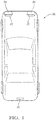
- FIG 1 schematically illustrates an example vehicle 20 including detector devices 22 that are configured for use with LIDAR sensing or signaling techniques.
- the devices 22 are useful, for example, for detecting objects in a vicinity or pathway of the vehicle 20.
- two of the detector devices 22 are associated with a headlamp 24 of the vehicle 20.
- At least one other detector device 22 is separate from a light source on the vehicle 20.
- a variety of placements of detector devices 22 on a vehicle are possible.
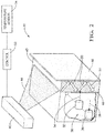
- FIG. 2 schematically illustrates an example configuration of at least one of the detector devices 22.
- a sensor portion 30 includes a transmitter or emitter 32 that emits a first type of radiation schematically shown at 34.
- a detector or receiver 36 detects at least some the first type of radiation that reflects off of an object (not illustrated) as schematically shown at 38.
- the first type of radiation comprises LIDAR radiation.
- the device 22 includes a cover or lens 40 that is transparent to the first type of radiation to allow the first type of radiation to pass through the cover 40.
- the cover 40 may comprise glass or a plastic material, for example.
- a source 42 of a second type of radiation schematically shown at 44 is situated to emit the second type of radiation 44 into the cover 40.
- a plurality of reflecting surfaces 46 and 48 are transparent to the first type of radiation 34, 38 and at least partially opaque to the second type of radiation 44.
- the reflecting surfaces 46 and 48 are situated relative to the cover 40 for reflecting at least a portion of the second type of radiation 44 into or within the cover 40.
- the source 42 directs the second type of radiation at an oblique angle relative to at least a portion of the reflecting surface 46 to facilitate reflection in the cover 40 between the reflecting surfaces 46 and 48.
- Such reflected radiation is schematically shown at 50 in the drawing.
- the second type of radiation 44 comprises infrared radiation. Reflecting infrared radiation within the cover 40 increases a temperature of at least the portion of the cover 40 where the infrared radiation is reflected. In some embodiments the temperature of the entire cover 40 will increase as a result of the reflected second type of radiation.
- the reflecting surfaces 46 and 48 in some embodiments are secured to outer surfaces of the cover 40. Coatings or films may serve as the reflecting surfaces 46 and 48. Another embodiment includes at least one of the reflecting surfaces 46 and 48 in the cover 40 instead of being on an outside or outer surface of the cover.
- the cover 40 may include a reflective layer inside the body of the cover 40.
- at least one of the reflecting surfaces 46 or 48 is separate from the cover 40 but positioned near it to accomplish the type of reflection schematically shown in Figure 2 .
- the reflecting surfaces 46 and 48 comprise a coating on outer surfaces of the cover 40.
- One such coating is a band pass filter commercially available from Alluxa.
- the filter in such an embodiment is selected to allow the first type of radiation to pass through the filter but not the second type of radiation.
- Other filters may be used as one or both of the reflecting surfaces 46, 48.
- at least one of the reflecting surfaces 46 or 48 comprises a grating.
- the reflecting surfaces may be a coating on the cover 40, a film on or in the cover 40, a layer on or in the cover 40, a grating near on or in the cover 40, a filter near on or in the cover 40, or a combination of those.
- the example device in Figure 2 includes a controller 52 that obtains information from at least one sensor 54 regarding environmental conditions, such as ambient temperature and humidity, or a temperature of the cover 40.
- environmental conditions such as ambient temperature and humidity, or a temperature of the cover 40.
- the controller 52 causes the source 42 of the second type of radiation to emit that radiation into the cover 40.
- the controller 52 receives input from a manual selector device that is available to a driver of a vehicle, for example, when heating the cover 40 is desired by that individual.
- Figure 3 schematically illustrates an example embodiment where the detector device 22 is incorporated as part of a vehicle headlamp assembly 60.
- the headlamp assembly 60 includes multiple light sources or bulbs 62 and 64. In normal operating conditions, visible light 66 is emitted by the bulbs 62 and 64 for illuminating the area in front of the vehicle 20, for example.
- a separator 70 is situated in a pathway of at least some of the light emitted by at least the bulb 64. The separator 70 separates out at least some of the second type of radiation 44 from the light 66.
- the separator 70 comprises a dichrolic prism configured to split infrared radiation from the light emitted by at least the bulb 64.
- the separator 70 comprises a grating that is configured to deflect or separate out infrared radiation from the light 66.
- a beam director 72 directs the second type of radiation 44 through a window or optical coupler 74 into the optical cover 40.
- the reflecting surfaces 46 and 48 reflect the second type of radiation 44 within lid 40 as schematically shown at 50.
- the reflected radiation within the cover 40 increases the temperature of at least that portion of the cover 40.
- the reflecting surfaces 46 and 48 are at least partially opaque to the second type of radiation such that at least some of the second type of radiation is reflected within the cover 40. In some instances, some of the second type of radiation will pass through or extend beyond one or both of the reflecting surfaces 46, 48. Provided that at least some of the radiation is reflected as schematically shown at 50, a desired heating effect will be achieved.
- a filter 78 is situated between the cover 40 and the sensor portion 30 to prevent any of such stray radiation of the second type from interfering with the operation of the sensor portion 30.
- the cover 40 near the sensor portion 30 is shown separate from the cover of the headlamp portion of the assembly.
- the sensor portion 30 is situated in the headlamp housing and the cover 40 is the cover for the entire headlamp assembly 60.
- the disclosed example embodiments have the ability to reduce or eliminate condensation or ice build-up on a cover or lens associated with a detector device.
- the disclosed example embodiments increase the reliability and availability of such detector devices for a wider range of environmental conditions.
Landscapes
- Engineering & Computer Science (AREA)
- Physics & Mathematics (AREA)
- Radar, Positioning & Navigation (AREA)
- Remote Sensing (AREA)
- General Physics & Mathematics (AREA)
- Computer Networks & Wireless Communication (AREA)
- Electromagnetism (AREA)
- Mechanical Engineering (AREA)
- Optics & Photonics (AREA)
- Optical Radar Systems And Details Thereof (AREA)
- Non-Portable Lighting Devices Or Systems Thereof (AREA)
- Lighting Device Outwards From Vehicle And Optical Signal (AREA)
Abstract
Description
- Innovations in electronics and technology have made it possible to incorporate a variety of advanced features on automotive vehicles. Various sensing technologies have been developed for detecting objects or monitoring the surroundings in a vicinity or pathway of a vehicle. Such systems are useful for parking assist, lane departure detection and cruise control adjustment features, for example.
- More recently, automated vehicle features have become possible to allow for autonomous or semi-autonomous vehicle control. Sensors for such systems may incorporate LIDAR (light detection and ranging) or RADAR for detecting an object or another vehicle in the pathway of or otherwise near the vehicle.
- Environmental conditions may be limiting on the availability or effectiveness of such sensing technologies. For example, in colder climates it is possible for ice or condensation to form or collect on the sensor window or casing. In those cases, the LIDAR transmission, reception or both may be compromised or even blocked entirely.
- Known heating technologies to prevent ice build-up tend to introduce additional complications or interfere with proper LIDAR sensor operation. For example, known heating circuits or coatings for windows or other surfaces interfere with or block LIDAR transmission through the window and, therefore, are not useful with LIDAR sensors. Other known options include separate heaters but those introduce other complications, such as providing a mounting location and wiring to power and control the heater.
- The availability and reliability of LIDAR sensing technologies for automotive vehicles would be enhanced by a solution to the problem discussed above.
- An illustrative example embodiment of a detector device includes a sensor portion that is configured to at least emit or receive a first type of radiation. A cover near the sensor portion is transparent to the first type of radiation to allow the first type of radiation to pass through the cover. A radiation source emits a second, different type of radiation into the cover. A plurality of reflecting surfaces are transparent to the first type of radiation and at least partially opaque to the second type of radiation to at least partially reflect the second type of radiation into the cover to increase a temperature of at least a portion of the cover.
- The first type of radiation may comprise LIDAR radiation. The second type of radiation may comprise infrared light. The reflecting surfaces may respectively comprise at least one of a coating on the cover, a film on or in the cover, a layer on or in the cover, a grating near, on or in the cover, and a filter near, on or in the cover. At least one of the reflecting surfaces may be an outer surface of the cover. The cover may have outer surfaces on opposite sides of the cover and the reflecting surfaces are respectively on the outer surfaces of the cover. The radiation source may emit the second type of radiation at an oblique angle relative to at least a portion of at least one of the reflecting surfaces.
- The detector device may comprise a separator that is configured to separate the second type of radiation from other radiation emitted by the radiation source, wherein the separated second type of radiation is directed toward at least one of the reflecting surfaces. The separator may comprise at least one of a prism or a grating. The radiation source may comprise a headlamp light.
- An illustrative example embodiment of a vehicle headlamp includes a light source and a cover near the light source. A sensor is situated near the cover such that the sensor at least emits or receives a first type of radiation through the cover. A plurality of reflecting surfaces are transparent to the first type of radiation and at least partially opaque to a second, different type of radiation. At least one separator separates at least the second type of radiation from light emitted by the light source and directs the second type of radiation into the cover where the reflecting surfaces at least partially reflect the second type of radiation within the cover to increase a temperature of at least a portion of the cover.
- The vehicle headlamp assembly may comprise a deflector that directs the separated second type of radiation toward at least one of the reflecting surfaces at an oblique angle relative to at least a portion of the at least one of the reflecting surfaces. The separator may comprise at least one of a dichrolic prism and a grating. The reflecting surfaces may respectively comprise at least one of a coating on the cover, a film on or in the cover, a layer on or in the cover, a grating near, on or in the cover, and a filter near, on or in the cover. The first type of radiation may comprise LIDAR radiation; and the second type of radiation may comprise infrared radiation.
- An illustrative example method of adjusting a temperature of a detector device cover that is transparent to a first type of radiation includes emitting a second, different type of radiation into at least a portion of the cover. The second type of radiation is reflected within the portion of the cover to increase a temperature of at least the portion of the cover.
- The first type of radiation may comprise LIDAR radiation. The second type of radiation may comprise infrared light.
- The method may comprise separating the second type of radiation from other radiation emitted by a radiation source; and directing the separated second type of radiation toward at least one of the reflecting surfaces. At least one of the reflecting surfaces may be an outer surface of the cover.
- Various features and advantages of at least one disclosed embodiment will become apparent to those skilled in the art from the following detailed description. The drawings that accompany the detailed description can be briefly described as follows.
-
-
Figure 1 schematically illustrates a vehicle including detector devices designed according to an embodiment of this invention. -
Figure 2 schematically illustrates selected components of an example detector device designed according to an embodiment of this invention. -
Figure 3 schematically illustrates selected components of a vehicle headlamp including an example detector device designed according to an embodiment of this invention. - Embodiments of this invention include detector devices that provide an ability to reduce or remove ice or condensation from the device to increase the availability and effectiveness of the detector device in a wider range of environmental conditions. Such devices are useful for a variety of vehicle applications, such as detectors on automated vehicles or semi-autonomous vehicles. Such detectors are also useful for assisting drivers of automotive vehicles.
-
Figure 1 schematically illustrates anexample vehicle 20 includingdetector devices 22 that are configured for use with LIDAR sensing or signaling techniques. Thedevices 22 are useful, for example, for detecting objects in a vicinity or pathway of thevehicle 20. As schematically shown inFigure 1 , two of thedetector devices 22 are associated with aheadlamp 24 of thevehicle 20. At least oneother detector device 22 is separate from a light source on thevehicle 20. A variety of placements ofdetector devices 22 on a vehicle are possible. -
Figure 2 schematically illustrates an example configuration of at least one of thedetector devices 22. Asensor portion 30 includes a transmitter oremitter 32 that emits a first type of radiation schematically shown at 34. A detector orreceiver 36 detects at least some the first type of radiation that reflects off of an object (not illustrated) as schematically shown at 38. In some embodiments the first type of radiation comprises LIDAR radiation. Thedevice 22 includes a cover orlens 40 that is transparent to the first type of radiation to allow the first type of radiation to pass through thecover 40. Thecover 40 may comprise glass or a plastic material, for example. - A
source 42 of a second type of radiation schematically shown at 44, is situated to emit the second type ofradiation 44 into thecover 40. A plurality of reflectingsurfaces radiation radiation 44. The reflectingsurfaces cover 40 for reflecting at least a portion of the second type ofradiation 44 into or within thecover 40. Thesource 42 directs the second type of radiation at an oblique angle relative to at least a portion of the reflectingsurface 46 to facilitate reflection in thecover 40 between the reflectingsurfaces - In the illustrated example, the second type of
radiation 44 comprises infrared radiation. Reflecting infrared radiation within thecover 40 increases a temperature of at least the portion of thecover 40 where the infrared radiation is reflected. In some embodiments the temperature of theentire cover 40 will increase as a result of the reflected second type of radiation. - The reflecting surfaces 46 and 48 in some embodiments are secured to outer surfaces of the
cover 40. Coatings or films may serve as the reflectingsurfaces surfaces cover 40 instead of being on an outside or outer surface of the cover. For example, thecover 40 may include a reflective layer inside the body of thecover 40. In another example embodiment, at least one of the reflectingsurfaces cover 40 but positioned near it to accomplish the type of reflection schematically shown inFigure 2 . - In one example embodiment, the reflecting
surfaces cover 40. One such coating is a band pass filter commercially available from Alluxa. The filter in such an embodiment is selected to allow the first type of radiation to pass through the filter but not the second type of radiation. Other filters may be used as one or both of the reflectingsurfaces surfaces - Given this description, those skilled in the art will realize that there are a variety of ways to incorporate a plurality of reflecting surfaces like the
surfaces cover 40 within which radiation, such as infrared radiation, will be reflected for purposes of heating at least that portion of the cover. The reflecting surfaces may be a coating on thecover 40, a film on or in thecover 40, a layer on or in thecover 40, a grating near on or in thecover 40, a filter near on or in thecover 40, or a combination of those. - The example device in
Figure 2 includes acontroller 52 that obtains information from at least onesensor 54 regarding environmental conditions, such as ambient temperature and humidity, or a temperature of thecover 40. When the conditions are conducive to condensation or ice build-up (e.g., the ambient temperature is sufficiently low) that could interfere with the first type of radiation passing through thecover 40, thecontroller 52 causes thesource 42 of the second type of radiation to emit that radiation into thecover 40. - In some embodiments, the
controller 52 receives input from a manual selector device that is available to a driver of a vehicle, for example, when heating thecover 40 is desired by that individual. -
Figure 3 schematically illustrates an example embodiment where thedetector device 22 is incorporated as part of avehicle headlamp assembly 60. In this example, theheadlamp assembly 60 includes multiple light sources orbulbs visible light 66 is emitted by thebulbs vehicle 20, for example. In the illustrated embodiment, aseparator 70 is situated in a pathway of at least some of the light emitted by at least thebulb 64. Theseparator 70 separates out at least some of the second type ofradiation 44 from the light 66. In one example, theseparator 70 comprises a dichrolic prism configured to split infrared radiation from the light emitted by at least thebulb 64. In another example, theseparator 70 comprises a grating that is configured to deflect or separate out infrared radiation from the light 66. - A
beam director 72 directs the second type ofradiation 44 through a window oroptical coupler 74 into theoptical cover 40. The reflecting surfaces 46 and 48 reflect the second type ofradiation 44 withinlid 40 as schematically shown at 50. The reflected radiation within thecover 40 increases the temperature of at least that portion of thecover 40. - The reflecting surfaces 46 and 48 are at least partially opaque to the second type of radiation such that at least some of the second type of radiation is reflected within the
cover 40. In some instances, some of the second type of radiation will pass through or extend beyond one or both of the reflectingsurfaces - Given that some of the second type of radiation may pass through the reflecting
surface 48, afilter 78 is situated between thecover 40 and thesensor portion 30 to prevent any of such stray radiation of the second type from interfering with the operation of thesensor portion 30. - In the illustrated example of
Figure 3 , thecover 40 near thesensor portion 30 is shown separate from the cover of the headlamp portion of the assembly. In other embodiments thesensor portion 30 is situated in the headlamp housing and thecover 40 is the cover for theentire headlamp assembly 60. - The disclosed example embodiments have the ability to reduce or eliminate condensation or ice build-up on a cover or lens associated with a detector device. The disclosed example embodiments increase the reliability and availability of such detector devices for a wider range of environmental conditions.
- While specific features or components are shown in connection with an example embodiment, those features or components are not necessarily limited to just that embodiment. Other combinations of the disclosed example features and components are possible to realize additional embodiments.
- The preceding description is exemplary rather than limiting in nature. Variations and modifications to the disclosed examples may become apparent to those skilled in the art that do not necessarily depart from the essence of this invention. The scope of legal protection given to this invention can only be determined by studying the following claims.
Claims (15)
- A detector device (22), comprising:a sensor portion (30) that is configured to at least emit or receive a first type of radiation (34);a cover (40) near the sensor portion (30), the cover (40) is transparent to the first type of radiation (34) to allow the first type of radiation (34) to pass through the cover (40);a radiation source (42) that emits a second type of radiation (44) into the cover (40), the second type of radiation (44) is different than the first type of radiation (34); anda plurality of reflecting surfaces (46, 48) that are transparent to the first type of radiation (34) and at least partially opaque to the second type of radiation (44) to at least partially reflect the second type of radiation (44) in the cover (40) to increase a temperature of at least a portion of the cover (40).
- The detector device (22) of claim 1, wherein the first type of radiation (34) comprises LIDAR radiation.
- The detector device (22) according to any one of the preceding claims, wherein the second type of radiation (44) comprises infrared light.
- The detector device (22) according to any one of the preceding claims, wherein the reflecting surfaces (46, 48) respectively comprise at least one of
a coating on the cover (40),
a film on or in the cover (40),
a layer on or in the cover (40),
a grating near, on or in the cover (40), and
a filter near, on or in the cover (40). - The detector device (22) according to any one of the preceding claims, wherein the radiation source (42) emits the second type of radiation (44) at an oblique angle relative to at least a portion of at least one of the reflecting surfaces (46,48).
- The detector device (22) according to any one of the preceding claims, comprising a separator (70) that is configured to separate the second type of radiation (44) from other radiation emitted by the radiation source (42), wherein the separated second type of radiation (44) is directed toward at least one of the reflecting surfaces (46,48).
- A method of adjusting a temperature of a detector device cover (40) that is transparent to a first type of radiation (34), the method comprising:emitting a second type of radiation (44), wherein the second type of radiation (44) is different from the first type of radiation (34); andreflecting at least some of the second type of radiation (44) from a plurality of reflecting surfaces (46, 48) that are transparent to the first type of radiation and at least partially opaque to the second type of radiation (44) in at least a portion of the cover (40) to thereby increase a temperature of at least the portion of the cover (40).
- The method of claim 7, wherein the first type of radiation (34) comprises LIDAR radiation.
- The method according to any one of the claims 7 or 8, wherein the second type of radiation (44) comprises infrared light.
- The method according to any one of the claims 7 to 9, comprising
separating the second type of radiation (44) from other radiation emitted by a radiation source (42); and
directing the separated second type of radiation (44) toward at least one of the reflecting surfaces (46, 48). - A vehicle headlamp assembly, comprising:at least one light source (62, 64);a sensor portion (30) that is configured to at least emit or receive a first type of radiation (34);a cover (40) near the sensor portion, the cover (40) is transparent to the first type of radiation to allow the first type of radiation to pass through the cover (40);a separator (70) that separates a second type of radiation (44) from light emitted by the light source (62, 64), the second type of radiation (44) is different than the first type of radiation (34); anda plurality of reflecting surfaces (46, 48) that are transparent to the first type of radiation (34) and at least partially opaque to the second type of radiation (44), the plurality of reflecting surfaces (46, 48) being situated to at least partially reflect the second type of radiation (44) in the cover (40) to increase a temperature of at least a portion of the cover (40).
- The vehicle headlamp assembly of claim 11, comprising a deflector that directs the separated second type of radiation (44) toward at least one of the reflecting surfaces (46, 48) at an oblique angle relative to at least a portion of the at least one of the reflecting surfaces (46, 48).
- The vehicle headlamp assembly according to any one of the claims 11 or 12, wherein the separator (70) comprises at least one of a dichrolic prism and a grating.
- The vehicle headlamp assembly according to any one of the claims 11 or 13, wherein the reflecting surfaces (46, 48) respectively comprise at least one of
a coating on the cover (40),
a film on or in the cover (40),
a layer on or in the cover (40),
a grating near, on or in the cover (40), and
a filter near, on or in the cover (40). - The vehicle headlamp assembly according to any one of the claims 11 or 14, whereinthe first type of radiation (34) comprises LIDAR radiation; andthe second type of radiation (44) comprises infrared radiation.
Applications Claiming Priority (1)
| Application Number | Priority Date | Filing Date | Title |
|---|---|---|---|
| US15/720,729 US10351103B2 (en) | 2017-09-29 | 2017-09-29 | LIDAR device with heated cover useful for automated vehicles |
Publications (3)
| Publication Number | Publication Date |
|---|---|
| EP3474040A2 true EP3474040A2 (en) | 2019-04-24 |
| EP3474040A3 EP3474040A3 (en) | 2019-07-10 |
| EP3474040B1 EP3474040B1 (en) | 2022-11-23 |
Family
ID=63685902
Family Applications (1)
| Application Number | Title | Priority Date | Filing Date |
|---|---|---|---|
| EP18197223.3A Active EP3474040B1 (en) | 2017-09-29 | 2018-09-27 | Lidar device with heated cover useful for automated vehicles |
Country Status (3)
| Country | Link |
|---|---|
| US (1) | US10351103B2 (en) |
| EP (1) | EP3474040B1 (en) |
| CN (1) | CN109581325B (en) |
Cited By (6)
| Publication number | Priority date | Publication date | Assignee | Title |
|---|---|---|---|---|
| FR3088597A1 (en) * | 2018-11-20 | 2020-05-22 | Valeo Vision | Vehicle part comprising a light device and a part opaque to visible light |
| DE102019103044A1 (en) * | 2019-02-07 | 2020-08-13 | Automotive Lighting Reutlingen Gmbh | Headlights of a motor vehicle |
| DE102019112324A1 (en) * | 2019-05-10 | 2020-11-12 | Automotive Lighting Reutlingen Gmbh | Headlights of a motor vehicle |
| WO2021001257A1 (en) * | 2019-07-03 | 2021-01-07 | HELLA GmbH & Co. KGaA | Device for heating a vehicle cover |
| CZ308648B6 (en) * | 2019-09-27 | 2021-01-27 | ŠKODA AUTO a.s. | Vehicle detection system assembly |
| WO2024063918A1 (en) * | 2022-09-22 | 2024-03-28 | Innovusion, Inc. | Radiant heater for defogging lidar aperture window |
Families Citing this family (11)
| Publication number | Priority date | Publication date | Assignee | Title |
|---|---|---|---|---|
| US11556000B1 (en) | 2019-08-22 | 2023-01-17 | Red Creamery Llc | Distally-actuated scanning mirror |
| US12123950B2 (en) | 2016-02-15 | 2024-10-22 | Red Creamery, LLC | Hybrid LADAR with co-planar scanning and imaging field-of-view |
| US12399278B1 (en) | 2016-02-15 | 2025-08-26 | Red Creamery Llc | Hybrid LIDAR with optically enhanced scanned laser |
| US12399279B1 (en) | 2016-02-15 | 2025-08-26 | Red Creamery Llc | Enhanced hybrid LIDAR with high-speed scanning |
| KR102393439B1 (en) * | 2018-05-15 | 2022-05-03 | 현대모비스 주식회사 | Lidar apparatus for vehicle |
| CN114008476A (en) * | 2019-04-26 | 2022-02-01 | 旭硝子欧洲玻璃公司 | Protective housing for a sensing device |
| CN111060919A (en) * | 2019-12-30 | 2020-04-24 | 广东博智林机器人有限公司 | Intelligent robot-based measuring method and intelligent robot |
| KR20210128179A (en) * | 2020-04-16 | 2021-10-26 | 주식회사 만도 | Lidar apparatus |
| DE102020126232A1 (en) | 2020-10-07 | 2022-04-07 | Valeo Schalter Und Sensoren Gmbh | Optical sensor system with heating |
| JP7699477B2 (en) * | 2021-06-15 | 2025-06-27 | スタンレー電気株式会社 | HEATER CONTROL DEVICE, HEATER CONTROL METHOD, AND VEHICLE LAMP |
| US20220219712A1 (en) * | 2022-03-31 | 2022-07-14 | Intel Corporation | Apparatus, system, and method of heating a window for a sensor device |
Family Cites Families (10)
| Publication number | Priority date | Publication date | Assignee | Title |
|---|---|---|---|---|
| US5417389A (en) * | 1993-02-19 | 1995-05-23 | Radiant Energy Corporation | Method of, and apparatus for, de-icing an aircraft by infrared radiation |
| WO2003066245A1 (en) * | 2002-02-01 | 2003-08-14 | Metastable Instruments, Inc. | Method and apparatus for cleaning with electromagnetic radiation |
| WO2011035259A1 (en) * | 2009-09-18 | 2011-03-24 | Pressco Technology Inc. | A narrowband de-icing and ice release system and method |
| DE102011103340A1 (en) * | 2011-06-03 | 2012-12-06 | Continental Automotive Gmbh | Device with optical sensor system and anti-fogging solution |
| JP2015517094A (en) | 2012-03-23 | 2015-06-18 | ウインダー フォトニクス エー/エスWindar Photonics A/S | Multi-directional LIDAR system |
| DE102013215470A1 (en) * | 2013-08-06 | 2015-02-12 | Bayerische Motoren Werke Aktiengesellschaft | Device and method for freeing a disc of a motor vehicle from moisture fitting and / or ice |
| FR3021753B1 (en) | 2014-05-28 | 2017-12-01 | Thales Sa | LIDAR COMPRISING OPTICAL MEANS FOR DEFROSTING OR PREVENTING GIFRAGE |
| DE102014110504A1 (en) * | 2014-07-25 | 2016-01-28 | Valeo Schalter Und Sensoren Gmbh | Scanning optoelectronic measuring device and use of a heat conductor of a cover of an optoelectronic measuring device |
| JP6643334B2 (en) * | 2014-11-03 | 2020-02-12 | イリノイ トゥール ワークス インコーポレイティド | Permeable front surface heater for vehicle sensor systems |
| CN106980118A (en) * | 2017-03-29 | 2017-07-25 | 惠州市德赛西威汽车电子股份有限公司 | The environment measuring device and its method of a kind of vehicle-mounted millimeter wave radar |
-
2017
- 2017-09-29 US US15/720,729 patent/US10351103B2/en active Active
-
2018
- 2018-09-27 CN CN201811135530.1A patent/CN109581325B/en active Active
- 2018-09-27 EP EP18197223.3A patent/EP3474040B1/en active Active
Non-Patent Citations (1)
| Title |
|---|
| None |
Cited By (10)
| Publication number | Priority date | Publication date | Assignee | Title |
|---|---|---|---|---|
| FR3088597A1 (en) * | 2018-11-20 | 2020-05-22 | Valeo Vision | Vehicle part comprising a light device and a part opaque to visible light |
| WO2020104208A1 (en) * | 2018-11-20 | 2020-05-28 | Valeo Vision | Vehicle portion comprising a luminous device and a part that is opaque to visible light |
| DE102019103044A1 (en) * | 2019-02-07 | 2020-08-13 | Automotive Lighting Reutlingen Gmbh | Headlights of a motor vehicle |
| DE102019103044B4 (en) | 2019-02-07 | 2023-09-14 | Automotive Lighting Reutlingen Gmbh | Headlights of a motor vehicle |
| DE102019112324A1 (en) * | 2019-05-10 | 2020-11-12 | Automotive Lighting Reutlingen Gmbh | Headlights of a motor vehicle |
| WO2021001257A1 (en) * | 2019-07-03 | 2021-01-07 | HELLA GmbH & Co. KGaA | Device for heating a vehicle cover |
| CN114008479A (en) * | 2019-07-03 | 2022-02-01 | 海拉有限双合股份公司 | Device for heating a cover of a vehicle |
| CN114008479B (en) * | 2019-07-03 | 2026-01-27 | 海拉有限双合股份公司 | Device for heating a cover of a vehicle |
| CZ308648B6 (en) * | 2019-09-27 | 2021-01-27 | ŠKODA AUTO a.s. | Vehicle detection system assembly |
| WO2024063918A1 (en) * | 2022-09-22 | 2024-03-28 | Innovusion, Inc. | Radiant heater for defogging lidar aperture window |
Also Published As
| Publication number | Publication date |
|---|---|
| EP3474040B1 (en) | 2022-11-23 |
| CN109581325A (en) | 2019-04-05 |
| US20190100167A1 (en) | 2019-04-04 |
| US10351103B2 (en) | 2019-07-16 |
| CN109581325B (en) | 2024-01-05 |
| EP3474040A3 (en) | 2019-07-10 |
Similar Documents
| Publication | Publication Date | Title |
|---|---|---|
| EP3474040B1 (en) | Lidar device with heated cover useful for automated vehicles | |
| US6376824B1 (en) | Optical sensor | |
| US10237920B2 (en) | Pane arrangement having an electrically heatable baffle plate | |
| US9777518B2 (en) | Collision protection device for a pivotable hatch of a motor vehicle, hatch, motor vehicle and corresponding method | |
| US10137842B2 (en) | Camera system for a vehicle | |
| JP3163889U (en) | An optical sensor device mounted on a vehicle for driving assistance and / or for automatically operating a system provided in the vehicle | |
| US10328843B2 (en) | Driving assistance system with short-distance ranging | |
| US20050180149A1 (en) | System and method of detecting driving conditions for a motor vehicle | |
| US20140247349A1 (en) | Integrated lighting, camera and sensor unit | |
| EP3091342A1 (en) | Optical sensor device for a vehicle | |
| US7148482B2 (en) | Multiple sensor thermal radiation detector and method | |
| KR102393439B1 (en) | Lidar apparatus for vehicle | |
| US10215359B2 (en) | Indicator optic for vehicle lighting module | |
| US20230194670A1 (en) | Baffle of a detection device for automotive vehicle | |
| KR20240042248A (en) | Sensor device and driver assistance system | |
| JP2002544505A (en) | Parameter detection device for detecting a parameter indicating the state of a vehicle | |
| CN102998678A (en) | Method for capturing an object in an environment of a motor vehicle | |
| CN110824455A (en) | Sensor system | |
| US20160339873A1 (en) | Illumination for Detecting Raindrops on a Pane by Means of a Camera | |
| EP2977275B1 (en) | Rain detection device | |
| JP6948881B2 (en) | Rain sensor | |
| CN114667456B (en) | Roof module with roof cladding and environmental sensors | |
| JPH0336180B2 (en) | ||
| KR20240147608A (en) | Environment detection system for a vehicle | |
| CN117716254A (en) | Heating system for a sensor unit in a vehicle |
Legal Events
| Date | Code | Title | Description |
|---|---|---|---|
| PUAI | Public reference made under article 153(3) epc to a published international application that has entered the european phase |
Free format text: ORIGINAL CODE: 0009012 |
|
| STAA | Information on the status of an ep patent application or granted ep patent |
Free format text: STATUS: THE APPLICATION HAS BEEN PUBLISHED |
|
| AK | Designated contracting states |
Kind code of ref document: A2 Designated state(s): AL AT BE BG CH CY CZ DE DK EE ES FI FR GB GR HR HU IE IS IT LI LT LU LV MC MK MT NL NO PL PT RO RS SE SI SK SM TR |
|
| AX | Request for extension of the european patent |
Extension state: BA ME |
|
| PUAL | Search report despatched |
Free format text: ORIGINAL CODE: 0009013 |
|
| AK | Designated contracting states |
Kind code of ref document: A3 Designated state(s): AL AT BE BG CH CY CZ DE DK EE ES FI FR GB GR HR HU IE IS IT LI LT LU LV MC MK MT NL NO PL PT RO RS SE SI SK SM TR |
|
| AX | Request for extension of the european patent |
Extension state: BA ME |
|
| RIC1 | Information provided on ipc code assigned before grant |
Ipc: G01S 13/93 20060101ALI20190603BHEP Ipc: B60Q 1/00 20060101ALI20190603BHEP Ipc: G01S 7/481 20060101ALI20190603BHEP Ipc: G01S 17/93 20060101AFI20190603BHEP |
|
| STAA | Information on the status of an ep patent application or granted ep patent |
Free format text: STATUS: REQUEST FOR EXAMINATION WAS MADE |
|
| 17P | Request for examination filed |
Effective date: 20200108 |
|
| RBV | Designated contracting states (corrected) |
Designated state(s): AL AT BE BG CH CY CZ DE DK EE ES FI FR GB GR HR HU IE IS IT LI LT LU LV MC MK MT NL NO PL PT RO RS SE SI SK SM TR |
|
| STAA | Information on the status of an ep patent application or granted ep patent |
Free format text: STATUS: EXAMINATION IS IN PROGRESS |
|
| 17Q | First examination report despatched |
Effective date: 20200708 |
|
| GRAP | Despatch of communication of intention to grant a patent |
Free format text: ORIGINAL CODE: EPIDOSNIGR1 |
|
| STAA | Information on the status of an ep patent application or granted ep patent |
Free format text: STATUS: GRANT OF PATENT IS INTENDED |
|
| INTG | Intention to grant announced |
Effective date: 20220831 |
|
| GRAS | Grant fee paid |
Free format text: ORIGINAL CODE: EPIDOSNIGR3 |
|
| GRAA | (expected) grant |
Free format text: ORIGINAL CODE: 0009210 |
|
| STAA | Information on the status of an ep patent application or granted ep patent |
Free format text: STATUS: THE PATENT HAS BEEN GRANTED |
|
| AK | Designated contracting states |
Kind code of ref document: B1 Designated state(s): AL AT BE BG CH CY CZ DE DK EE ES FI FR GB GR HR HU IE IS IT LI LT LU LV MC MK MT NL NO PL PT RO RS SE SI SK SM TR |
|
| REG | Reference to a national code |
Ref country code: GB Ref legal event code: FG4D |
|
| REG | Reference to a national code |
Ref country code: CH Ref legal event code: EP |
|
| REG | Reference to a national code |
Ref country code: AT Ref legal event code: REF Ref document number: 1533467 Country of ref document: AT Kind code of ref document: T Effective date: 20221215 Ref country code: DE Ref legal event code: R096 Ref document number: 602018043310 Country of ref document: DE |
|
| REG | Reference to a national code |
Ref country code: IE Ref legal event code: FG4D |
|
| REG | Reference to a national code |
Ref country code: LT Ref legal event code: MG9D |
|
| RAP4 | Party data changed (patent owner data changed or rights of a patent transferred) |
Owner name: APTIV TECHNOLOGIES LIMITED |
|
| REG | Reference to a national code |
Ref country code: NL Ref legal event code: MP Effective date: 20221123 |
|
| REG | Reference to a national code |
Ref country code: AT Ref legal event code: MK05 Ref document number: 1533467 Country of ref document: AT Kind code of ref document: T Effective date: 20221123 |
|
| PG25 | Lapsed in a contracting state [announced via postgrant information from national office to epo] |
Ref country code: SE Free format text: LAPSE BECAUSE OF FAILURE TO SUBMIT A TRANSLATION OF THE DESCRIPTION OR TO PAY THE FEE WITHIN THE PRESCRIBED TIME-LIMIT Effective date: 20221123 Ref country code: PT Free format text: LAPSE BECAUSE OF FAILURE TO SUBMIT A TRANSLATION OF THE DESCRIPTION OR TO PAY THE FEE WITHIN THE PRESCRIBED TIME-LIMIT Effective date: 20230323 Ref country code: NO Free format text: LAPSE BECAUSE OF FAILURE TO SUBMIT A TRANSLATION OF THE DESCRIPTION OR TO PAY THE FEE WITHIN THE PRESCRIBED TIME-LIMIT Effective date: 20230223 Ref country code: LT Free format text: LAPSE BECAUSE OF FAILURE TO SUBMIT A TRANSLATION OF THE DESCRIPTION OR TO PAY THE FEE WITHIN THE PRESCRIBED TIME-LIMIT Effective date: 20221123 Ref country code: FI Free format text: LAPSE BECAUSE OF FAILURE TO SUBMIT A TRANSLATION OF THE DESCRIPTION OR TO PAY THE FEE WITHIN THE PRESCRIBED TIME-LIMIT Effective date: 20221123 Ref country code: ES Free format text: LAPSE BECAUSE OF FAILURE TO SUBMIT A TRANSLATION OF THE DESCRIPTION OR TO PAY THE FEE WITHIN THE PRESCRIBED TIME-LIMIT Effective date: 20221123 Ref country code: AT Free format text: LAPSE BECAUSE OF FAILURE TO SUBMIT A TRANSLATION OF THE DESCRIPTION OR TO PAY THE FEE WITHIN THE PRESCRIBED TIME-LIMIT Effective date: 20221123 |
|
| PG25 | Lapsed in a contracting state [announced via postgrant information from national office to epo] |
Ref country code: RS Free format text: LAPSE BECAUSE OF FAILURE TO SUBMIT A TRANSLATION OF THE DESCRIPTION OR TO PAY THE FEE WITHIN THE PRESCRIBED TIME-LIMIT Effective date: 20221123 Ref country code: PL Free format text: LAPSE BECAUSE OF FAILURE TO SUBMIT A TRANSLATION OF THE DESCRIPTION OR TO PAY THE FEE WITHIN THE PRESCRIBED TIME-LIMIT Effective date: 20221123 Ref country code: LV Free format text: LAPSE BECAUSE OF FAILURE TO SUBMIT A TRANSLATION OF THE DESCRIPTION OR TO PAY THE FEE WITHIN THE PRESCRIBED TIME-LIMIT Effective date: 20221123 Ref country code: IS Free format text: LAPSE BECAUSE OF FAILURE TO SUBMIT A TRANSLATION OF THE DESCRIPTION OR TO PAY THE FEE WITHIN THE PRESCRIBED TIME-LIMIT Effective date: 20230323 Ref country code: HR Free format text: LAPSE BECAUSE OF FAILURE TO SUBMIT A TRANSLATION OF THE DESCRIPTION OR TO PAY THE FEE WITHIN THE PRESCRIBED TIME-LIMIT Effective date: 20221123 Ref country code: GR Free format text: LAPSE BECAUSE OF FAILURE TO SUBMIT A TRANSLATION OF THE DESCRIPTION OR TO PAY THE FEE WITHIN THE PRESCRIBED TIME-LIMIT Effective date: 20230224 |
|
| P01 | Opt-out of the competence of the unified patent court (upc) registered |
Effective date: 20230414 |
|
| PG25 | Lapsed in a contracting state [announced via postgrant information from national office to epo] |
Ref country code: NL Free format text: LAPSE BECAUSE OF FAILURE TO SUBMIT A TRANSLATION OF THE DESCRIPTION OR TO PAY THE FEE WITHIN THE PRESCRIBED TIME-LIMIT Effective date: 20221123 |
|
| PG25 | Lapsed in a contracting state [announced via postgrant information from national office to epo] |
Ref country code: SM Free format text: LAPSE BECAUSE OF FAILURE TO SUBMIT A TRANSLATION OF THE DESCRIPTION OR TO PAY THE FEE WITHIN THE PRESCRIBED TIME-LIMIT Effective date: 20221123 Ref country code: RO Free format text: LAPSE BECAUSE OF FAILURE TO SUBMIT A TRANSLATION OF THE DESCRIPTION OR TO PAY THE FEE WITHIN THE PRESCRIBED TIME-LIMIT Effective date: 20221123 Ref country code: EE Free format text: LAPSE BECAUSE OF FAILURE TO SUBMIT A TRANSLATION OF THE DESCRIPTION OR TO PAY THE FEE WITHIN THE PRESCRIBED TIME-LIMIT Effective date: 20221123 Ref country code: DK Free format text: LAPSE BECAUSE OF FAILURE TO SUBMIT A TRANSLATION OF THE DESCRIPTION OR TO PAY THE FEE WITHIN THE PRESCRIBED TIME-LIMIT Effective date: 20221123 Ref country code: CZ Free format text: LAPSE BECAUSE OF FAILURE TO SUBMIT A TRANSLATION OF THE DESCRIPTION OR TO PAY THE FEE WITHIN THE PRESCRIBED TIME-LIMIT Effective date: 20221123 |
|
| REG | Reference to a national code |
Ref country code: DE Ref legal event code: R097 Ref document number: 602018043310 Country of ref document: DE |
|
| PG25 | Lapsed in a contracting state [announced via postgrant information from national office to epo] |
Ref country code: SK Free format text: LAPSE BECAUSE OF FAILURE TO SUBMIT A TRANSLATION OF THE DESCRIPTION OR TO PAY THE FEE WITHIN THE PRESCRIBED TIME-LIMIT Effective date: 20221123 Ref country code: AL Free format text: LAPSE BECAUSE OF FAILURE TO SUBMIT A TRANSLATION OF THE DESCRIPTION OR TO PAY THE FEE WITHIN THE PRESCRIBED TIME-LIMIT Effective date: 20221123 |
|
| PLBE | No opposition filed within time limit |
Free format text: ORIGINAL CODE: 0009261 |
|
| STAA | Information on the status of an ep patent application or granted ep patent |
Free format text: STATUS: NO OPPOSITION FILED WITHIN TIME LIMIT |
|
| 26N | No opposition filed |
Effective date: 20230824 |
|
| PG25 | Lapsed in a contracting state [announced via postgrant information from national office to epo] |
Ref country code: SI Free format text: LAPSE BECAUSE OF FAILURE TO SUBMIT A TRANSLATION OF THE DESCRIPTION OR TO PAY THE FEE WITHIN THE PRESCRIBED TIME-LIMIT Effective date: 20221123 |
|
| REG | Reference to a national code |
Ref country code: CH Ref legal event code: PL |
|
| PG25 | Lapsed in a contracting state [announced via postgrant information from national office to epo] |
Ref country code: LU Free format text: LAPSE BECAUSE OF NON-PAYMENT OF DUE FEES Effective date: 20230927 |
|
| REG | Reference to a national code |
Ref country code: BE Ref legal event code: MM Effective date: 20230930 |
|
| PG25 | Lapsed in a contracting state [announced via postgrant information from national office to epo] |
Ref country code: LU Free format text: LAPSE BECAUSE OF NON-PAYMENT OF DUE FEES Effective date: 20230927 Ref country code: IT Free format text: LAPSE BECAUSE OF FAILURE TO SUBMIT A TRANSLATION OF THE DESCRIPTION OR TO PAY THE FEE WITHIN THE PRESCRIBED TIME-LIMIT Effective date: 20221123 Ref country code: MC Free format text: LAPSE BECAUSE OF FAILURE TO SUBMIT A TRANSLATION OF THE DESCRIPTION OR TO PAY THE FEE WITHIN THE PRESCRIBED TIME-LIMIT Effective date: 20221123 |
|
| REG | Reference to a national code |
Ref country code: IE Ref legal event code: MM4A |
|
| PG25 | Lapsed in a contracting state [announced via postgrant information from national office to epo] |
Ref country code: IE Free format text: LAPSE BECAUSE OF NON-PAYMENT OF DUE FEES Effective date: 20230927 |
|
| PG25 | Lapsed in a contracting state [announced via postgrant information from national office to epo] |
Ref country code: CH Free format text: LAPSE BECAUSE OF NON-PAYMENT OF DUE FEES Effective date: 20230930 |
|
| PG25 | Lapsed in a contracting state [announced via postgrant information from national office to epo] |
Ref country code: IE Free format text: LAPSE BECAUSE OF NON-PAYMENT OF DUE FEES Effective date: 20230927 Ref country code: CH Free format text: LAPSE BECAUSE OF NON-PAYMENT OF DUE FEES Effective date: 20230930 |
|
| PG25 | Lapsed in a contracting state [announced via postgrant information from national office to epo] |
Ref country code: BE Free format text: LAPSE BECAUSE OF NON-PAYMENT OF DUE FEES Effective date: 20230930 |
|
| PG25 | Lapsed in a contracting state [announced via postgrant information from national office to epo] |
Ref country code: BG Free format text: LAPSE BECAUSE OF FAILURE TO SUBMIT A TRANSLATION OF THE DESCRIPTION OR TO PAY THE FEE WITHIN THE PRESCRIBED TIME-LIMIT Effective date: 20221123 |
|
| PG25 | Lapsed in a contracting state [announced via postgrant information from national office to epo] |
Ref country code: BG Free format text: LAPSE BECAUSE OF FAILURE TO SUBMIT A TRANSLATION OF THE DESCRIPTION OR TO PAY THE FEE WITHIN THE PRESCRIBED TIME-LIMIT Effective date: 20221123 |
|
| REG | Reference to a national code |
Ref country code: DE Ref legal event code: R081 Ref document number: 602018043310 Country of ref document: DE Owner name: APTIV TECHNOLOGIES AG, CH Free format text: FORMER OWNER: APTIV TECHNOLOGIES LIMITED, ST. MICHAEL, BB |
|
| PG25 | Lapsed in a contracting state [announced via postgrant information from national office to epo] |
Ref country code: CY Free format text: LAPSE BECAUSE OF FAILURE TO SUBMIT A TRANSLATION OF THE DESCRIPTION OR TO PAY THE FEE WITHIN THE PRESCRIBED TIME-LIMIT; INVALID AB INITIO Effective date: 20180927 |
|
| PG25 | Lapsed in a contracting state [announced via postgrant information from national office to epo] |
Ref country code: HU Free format text: LAPSE BECAUSE OF FAILURE TO SUBMIT A TRANSLATION OF THE DESCRIPTION OR TO PAY THE FEE WITHIN THE PRESCRIBED TIME-LIMIT; INVALID AB INITIO Effective date: 20180927 |
|
| PGFP | Annual fee paid to national office [announced via postgrant information from national office to epo] |
Ref country code: DE Payment date: 20250814 Year of fee payment: 8 |
|
| PGFP | Annual fee paid to national office [announced via postgrant information from national office to epo] |
Ref country code: GB Payment date: 20250924 Year of fee payment: 8 |
|
| PGFP | Annual fee paid to national office [announced via postgrant information from national office to epo] |
Ref country code: FR Payment date: 20250908 Year of fee payment: 8 |
|
| PG25 | Lapsed in a contracting state [announced via postgrant information from national office to epo] |
Ref country code: TR Free format text: LAPSE BECAUSE OF FAILURE TO SUBMIT A TRANSLATION OF THE DESCRIPTION OR TO PAY THE FEE WITHIN THE PRESCRIBED TIME-LIMIT Effective date: 20221123 |