EP3473993A1 - Methods and apparatus to reduce static pressure measuring error - Google Patents
Methods and apparatus to reduce static pressure measuring error Download PDFInfo
- Publication number
- EP3473993A1 EP3473993A1 EP18198700.9A EP18198700A EP3473993A1 EP 3473993 A1 EP3473993 A1 EP 3473993A1 EP 18198700 A EP18198700 A EP 18198700A EP 3473993 A1 EP3473993 A1 EP 3473993A1
- Authority
- EP
- European Patent Office
- Prior art keywords
- static pressure
- porous material
- opening
- membrane
- vehicle
- Prior art date
- Legal status (The legal status is an assumption and is not a legal conclusion. Google has not performed a legal analysis and makes no representation as to the accuracy of the status listed.)
- Granted
Links
Images




Classifications
-
- G—PHYSICS
- G01—MEASURING; TESTING
- G01L—MEASURING FORCE, STRESS, TORQUE, WORK, MECHANICAL POWER, MECHANICAL EFFICIENCY, OR FLUID PRESSURE
- G01L19/00—Details of, or accessories for, apparatus for measuring steady or quasi-steady pressure of a fluent medium insofar as such details or accessories are not special to particular types of pressure gauges
- G01L19/0007—Fluidic connecting means
- G01L19/0038—Fluidic connecting means being part of the housing
-
- G—PHYSICS
- G01—MEASURING; TESTING
- G01L—MEASURING FORCE, STRESS, TORQUE, WORK, MECHANICAL POWER, MECHANICAL EFFICIENCY, OR FLUID PRESSURE
- G01L19/00—Details of, or accessories for, apparatus for measuring steady or quasi-steady pressure of a fluent medium insofar as such details or accessories are not special to particular types of pressure gauges
-
- B—PERFORMING OPERATIONS; TRANSPORTING
- B64—AIRCRAFT; AVIATION; COSMONAUTICS
- B64D—EQUIPMENT FOR FITTING IN OR TO AIRCRAFT; FLIGHT SUITS; PARACHUTES; ARRANGEMENT OR MOUNTING OF POWER PLANTS OR PROPULSION TRANSMISSIONS IN AIRCRAFT
- B64D43/00—Arrangements or adaptations of instruments
- B64D43/02—Arrangements or adaptations of instruments for indicating aircraft speed or stalling conditions
-
- G—PHYSICS
- G01—MEASURING; TESTING
- G01K—MEASURING TEMPERATURE; MEASURING QUANTITY OF HEAT; THERMALLY-SENSITIVE ELEMENTS NOT OTHERWISE PROVIDED FOR
- G01K13/00—Thermometers specially adapted for specific purposes
- G01K13/02—Thermometers specially adapted for specific purposes for measuring temperature of moving fluids or granular materials capable of flow
-
- G—PHYSICS
- G01—MEASURING; TESTING
- G01L—MEASURING FORCE, STRESS, TORQUE, WORK, MECHANICAL POWER, MECHANICAL EFFICIENCY, OR FLUID PRESSURE
- G01L19/00—Details of, or accessories for, apparatus for measuring steady or quasi-steady pressure of a fluent medium insofar as such details or accessories are not special to particular types of pressure gauges
- G01L19/0007—Fluidic connecting means
- G01L19/0046—Fluidic connecting means using isolation membranes
-
- G—PHYSICS
- G01—MEASURING; TESTING
- G01L—MEASURING FORCE, STRESS, TORQUE, WORK, MECHANICAL POWER, MECHANICAL EFFICIENCY, OR FLUID PRESSURE
- G01L19/00—Details of, or accessories for, apparatus for measuring steady or quasi-steady pressure of a fluent medium insofar as such details or accessories are not special to particular types of pressure gauges
- G01L19/06—Means for preventing overload or deleterious influence of the measured medium on the measuring device or vice versa
- G01L19/0609—Pressure pulsation damping arrangements
-
- G—PHYSICS
- G01—MEASURING; TESTING
- G01P—MEASURING LINEAR OR ANGULAR SPEED, ACCELERATION, DECELERATION, OR SHOCK; INDICATING PRESENCE, ABSENCE, OR DIRECTION, OF MOVEMENT
- G01P13/00—Indicating or recording presence, absence, or direction, of movement
- G01P13/0006—Indicating or recording presence, absence, or direction, of movement of fluids or of granulous or powder-like substances
- G01P13/0013—Indicating or recording presence, absence, or direction, of movement of fluids or of granulous or powder-like substances by using a solid body which is shifted by the action of the fluid
-
- G—PHYSICS
- G01—MEASURING; TESTING
- G01P—MEASURING LINEAR OR ANGULAR SPEED, ACCELERATION, DECELERATION, OR SHOCK; INDICATING PRESENCE, ABSENCE, OR DIRECTION, OF MOVEMENT
- G01P13/00—Indicating or recording presence, absence, or direction, of movement
- G01P13/0006—Indicating or recording presence, absence, or direction, of movement of fluids or of granulous or powder-like substances
- G01P13/0066—Indicating or recording presence, absence, or direction, of movement of fluids or of granulous or powder-like substances by using differences of pressure in the fluid
-
- G—PHYSICS
- G01—MEASURING; TESTING
- G01P—MEASURING LINEAR OR ANGULAR SPEED, ACCELERATION, DECELERATION, OR SHOCK; INDICATING PRESENCE, ABSENCE, OR DIRECTION, OF MOVEMENT
- G01P13/00—Indicating or recording presence, absence, or direction, of movement
- G01P13/02—Indicating direction only, e.g. by weather vane
- G01P13/025—Indicating direction only, e.g. by weather vane indicating air data, i.e. flight variables of an aircraft, e.g. angle of attack, side slip, shear, yaw
-
- G—PHYSICS
- G01—MEASURING; TESTING
- G01P—MEASURING LINEAR OR ANGULAR SPEED, ACCELERATION, DECELERATION, OR SHOCK; INDICATING PRESENCE, ABSENCE, OR DIRECTION, OF MOVEMENT
- G01P13/00—Indicating or recording presence, absence, or direction, of movement
- G01P13/02—Indicating direction only, e.g. by weather vane
- G01P13/04—Indicating positive or negative direction of a linear movement or clockwise or anti-clockwise direction of a rotational movement
- G01P13/045—Indicating positive or negative direction of a linear movement or clockwise or anti-clockwise direction of a rotational movement with speed indication
-
- G—PHYSICS
- G01—MEASURING; TESTING
- G01P—MEASURING LINEAR OR ANGULAR SPEED, ACCELERATION, DECELERATION, OR SHOCK; INDICATING PRESENCE, ABSENCE, OR DIRECTION, OF MOVEMENT
- G01P5/00—Measuring speed of fluids, e.g. of air stream; Measuring speed of bodies relative to fluids, e.g. of ship, of aircraft
- G01P5/005—Measuring speed of fluids, e.g. of air stream; Measuring speed of bodies relative to fluids, e.g. of ship, of aircraft by using a jet directed into the fluid
-
- G—PHYSICS
- G01—MEASURING; TESTING
- G01P—MEASURING LINEAR OR ANGULAR SPEED, ACCELERATION, DECELERATION, OR SHOCK; INDICATING PRESENCE, ABSENCE, OR DIRECTION, OF MOVEMENT
- G01P5/00—Measuring speed of fluids, e.g. of air stream; Measuring speed of bodies relative to fluids, e.g. of ship, of aircraft
- G01P5/14—Measuring speed of fluids, e.g. of air stream; Measuring speed of bodies relative to fluids, e.g. of ship, of aircraft by measuring differences of pressure in the fluid
- G01P5/16—Measuring speed of fluids, e.g. of air stream; Measuring speed of bodies relative to fluids, e.g. of ship, of aircraft by measuring differences of pressure in the fluid using Pitot tubes, e.g. Machmeter
-
- G—PHYSICS
- G01—MEASURING; TESTING
- G01P—MEASURING LINEAR OR ANGULAR SPEED, ACCELERATION, DECELERATION, OR SHOCK; INDICATING PRESENCE, ABSENCE, OR DIRECTION, OF MOVEMENT
- G01P5/00—Measuring speed of fluids, e.g. of air stream; Measuring speed of bodies relative to fluids, e.g. of ship, of aircraft
- G01P5/14—Measuring speed of fluids, e.g. of air stream; Measuring speed of bodies relative to fluids, e.g. of ship, of aircraft by measuring differences of pressure in the fluid
- G01P5/16—Measuring speed of fluids, e.g. of air stream; Measuring speed of bodies relative to fluids, e.g. of ship, of aircraft by measuring differences of pressure in the fluid using Pitot tubes, e.g. Machmeter
- G01P5/165—Arrangements or constructions of Pitot tubes
-
- G—PHYSICS
- G01—MEASURING; TESTING
- G01K—MEASURING TEMPERATURE; MEASURING QUANTITY OF HEAT; THERMALLY-SENSITIVE ELEMENTS NOT OTHERWISE PROVIDED FOR
- G01K13/00—Thermometers specially adapted for specific purposes
- G01K13/02—Thermometers specially adapted for specific purposes for measuring temperature of moving fluids or granular materials capable of flow
- G01K13/024—Thermometers specially adapted for specific purposes for measuring temperature of moving fluids or granular materials capable of flow of moving gases
Definitions
- This disclosure relates generally to measuring static pressure measurements and, more particularly, to methods and apparatus to reduce static pressure measuring error.
- static pressure taps are utilized on vehicles, such as aircraft, to measure static pressure during various stages of operations (e.g., flight, idling on the ground, etc.). In particular, the static pressure may be measured to calculate a velocity of the aircraft.
- an opening of a static pressure tap of a vehicle is positioned along a surface across which air flows (e.g., the air flows perpendicular to the opening).
- a sensor is disposed within the vehicle at a defined distance from the opening so that the sensor is not substantially affected by a dynamic pressure component that can skew pressure measurements.
- An example apparatus to measure static pressure includes a static pressure tap having a channel to define an external opening of a vehicle, where the channel extends through a pressure chamber to a pressure sensor disposed within, and a porous material disposed proximate the opening to reduce error in static pressure measurements.
- An example vehicle includes an external surface, a static pressure tap defining an opening of the external surface and a channel extending to a pressure chamber, a pressure sensor disposed within or proximate the pressure chamber, and a porous material proximate the opening and substantially covering the opening to reduce error associated with the pressure sensor.
- An example method of reducing error of a static pressure sensor of a vehicle includes providing porous material proximate an opening of a static pressure tap, where the opening at least partially defines an external surface of the vehicle, and where a channel extends from the opening to a pressure chamber having a pressure sensor disposed within.
- any part e.g., a layer, film, area, or plate
- any part indicates that the referenced part is either in contact with the other part, or that the referenced part is above the other part with one or more intermediate part(s) located therebetween.
- Stating that any part is in contact with another part means that there is no intermediate part between the two parts.
- Static pressure taps are used on vehicles, such as aircraft, to measure a static pressure during various stages of vehicle operations (e.g., flight).
- the static pressure is typically measured by a static pressure tap to determine a velocity or airspeed of the vehicle.
- an accurate static pressure measurement is vital to make an accurate determination of velocity.
- Some known static pressure taps allow turbulent airflow to move into the static pressure tap, thereby adversely affecting an accuracy of a pressure sensor disposed within the static pressure tap. In other words, this turbulent airflow moving into the static pressure tap may skew measurements of the pressure sensor.
- the examples disclosed herein provide highly accurate static pressure measurements.
- the examples disclosed herein utilize porous material disposed proximate an opening of a channel that defines an external opening of a vehicle (e.g., an aircraft), where the channel extends to a pressure chamber having a pressure sensor disposed within.
- the porous material reduces error in static pressure measurements made by the sensor, thereby enabling highly accurate determinations of velocity and/or speed, for example.
- the aforementioned porous material includes a membrane substantially covering the channel to define the external opening. Additionally or alternatively, the porous material includes a porous material plug. In some examples, a porous material plug is coupled to the membrane and extends in a direction generally towards the pressure chamber. Additionally or alternatively, a surface of the porous material is aligned (e.g., flush) with an external surface of a vehicle.
- the porous material includes a woven fabric material to provide a flow resistance of the porous material between approximately 1 Rayl (centimeter gram second (CGS)) and approximately 1000 Rayl.
- the porous material is composed of at least one of polyether ether ketone (PEEK), polyaryl ether ketone (PAEK) or polyether ketone ketone (PEKK).
- the porous material includes a fabric membrane with a thickness between approximately 0.003 inches and 0.100 inches (between approximately 0.076 mm and 2.5 mm).
- the term “static pressure tap” refers to components, an assembly and/or an integrated component that is used to measure a static pressure.
- the term “porous material” refers to a material, composite material, a sponge-like material, a cloth-like material, a cellular material and/or material matrix with openings and/or cellular voids, which may be open or closed (e.g., external openings, internal openings, closed internal volumes, openings extending through a thickness, etc.).
- openings and/or cellular voids which may be open or closed (e.g., external openings, internal openings, closed internal volumes, openings extending through a thickness, etc.).
- stating that anything is “aligned” or “flush with” another means that first and second components are approximately between 0 to 10 millimeters (mm) from one another.
- FIG. 1A illustrates an example aircraft 100 in which the examples disclosed herein may be implemented.
- the example aircraft 100 includes a fuselage 102 and wings 104 (e.g., a right wing and a left wing) extending laterally outward from the fuselage 102.
- the example aircraft 100 also includes a known static pressure tap 106 that is positioned adjacent a nose 108 of the aircraft 100.
- the static pressure tap 106 may be placed anywhere on the fuselage 102, the wings 104 or any appropriate outboard structure of the aircraft 100.
- the static pressure tap 106 is positioned on the aircraft 100 such that air flows across (e.g., perpendicular to) the static pressure tap 106, but does not significantly enter the static pressure tap to mitigate skewing (e.g., contamination, biasing, etc.) by a dynamic pressure component of a static pressure measured at the static pressure tap 106.
- FIG. 1B is a detailed view of the static pressure tap 106 depicting an opening 110 of the known static pressure tap 106 of FIG. 1A .
- the opening 110 of the static pressure tap 106 is a hole or opening that facilitates measurement of a static pressure component by a pressure sensor disposed within the static pressure tap 106.
- the opening 110 of the known static pressure tap 106 is typically flush with an external surface (e.g., a wall, an external wall) 112 of the aircraft 100.
- FIG. 1C is a cross-sectional view of the known static pressure tap 106 of FIGS. 1A and 1B .
- the static pressure tap 106 includes a channel 114 extending from the opening 110 to a chamber 116. Further, a pressure sensor 118 is disposed within the chamber 116 of the static pressure tap 106.
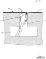
- FIG. 2 is a cross-sectional view illustrating pressure gradients of example airflow 202 across the static pressure tap 106 shown in FIGS. 1A-1C .
- the example airflow 202 flows substantially across the opening 110 of the static pressure tap 106.
- the air may also at least partially flow into the channel 114, thereby causing turbulent airflow 204 within the channel 114 as well as the chamber 116, thereby negatively affecting measurements of the pressure sensor 118 by introducing dynamic pressure components.
- error associated with the static pressure measurement can affect a velocity or airspeed determination.
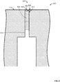
- FIG. 3 depicts an example static pressure tap 300 to reduce error in static pressure measurements in accordance with the teachings of this disclosure.
- the static pressure tap 300 of the illustrated example includes a porous membrane (e.g., a porous material membrane, a membrane made of a porous material) 302 positioned across an opening 304 of the static pressure tap 300 to reduce and/or substantially prevent turbulent airflow within a channel 306 and/or a chamber 308.
- the example porous membrane 302 is positioned such that a surface (e.g., an outer surface) 310 of the porous membrane 302 is flush and/or substantially aligned with the external surface 112 of the example aircraft 100.
- the porous membrane 302 is offset at a defined distance 312 from (i.e., is not flush relative to) the external surface 112.
- the porous membrane can be offset in a range from 0 to 20 mm.
- the porous membrane 302 may be offset to facilitate manufacturing and/or installation of the porous membrane 302.
- the example offset dimensions are only examples and any appropriate offset dimension(s) may be utilized based on application, vehicle design and/or vehicle use, etc.
- the porous membrane 302 is coupled to and/or installed on or within the static pressure tap 300 via an adhesive, an adhesive tape, a clamp, and/or any other suitable fastener.
- the static pressure tap 300 may include a groove (e.g., an annular groove) 314 into which the porous membrane 302 is at least partially inserted during manufacturing.
- the porous membrane 302 may be retrofitted to existing static pressure taps (e.g., the static pressure tap 106 is retrofitted with the porous membrane 302).
- the porous membrane 302 of the illustrated example may have a thickness between approximately 0.003 inches and 0.100 inches (between approximately 0.076 mm and 2.5 mm). However, the porous membrane 302 may have any appropriate thickness suitable to prevent turbulent airflow within the channel 306 and/or the chamber 308 based on application need(s). In this example, the porous membrane 302 has a flow resistance between approximately 1 Rayl and approximately 1000 Rayl. However, any appropriate flow resistance may be utilized.
- the porous membrane 302 may be any material having a suitable flow resistance and thickness. In some examples, the porous membrane 302 is selected and/or designed to satisfy other considerations, such as durability requirements, fire-resistance standards, etc.
- the porous membrane 302 may include thermoplastic fibers, such as PEEK, PAEK and/or PEKK, etc.
- the porous membrane 302 enables air to pass therethrough such that a pressure sensor (e.g., the pressure sensor 118) can accurately measure static pressure and/or a variation (or shift) of the static pressure.
- a pressure sensor e.g., the pressure sensor 118
- turbulent airflow which has dynamic pressure components that can skew measurement(s) of the static pressure, is substantially prevented (e.g., fully prevented) from entering the channel 306 and/or the chamber 308.
- FIG. 4 depicts another example static pressure tap 400 in accordance with the teachings of this disclosure.
- the example static pressure tap 400 is similar to the example static pressure tap 300, but includes a porous plug (e.g., a porous material formed into a plug, a porous material plug, etc.) 402 instead of the porous material membrane 302.
- the example porous plug 402 is disposed adjacent an opening 403 of a channel 404 and extends towards a chamber 406.
- the example porous plug 402 includes a surface (e.g., an outer surface, an upper surface) 408 that is substantially aligned with (e.g., flush with) the external surface 112 of the aircraft 100.
- the surface 408 of the porous plug 402 may be offset by a distance 410 from the external surface 112 (e.g., at an offset distance of 0 to 20 mm).
- the porous plug 402 may be coupled to and/or installed in the static pressure tap 400 using an adhesive, adhesive tape, a clamp, or any other suitable fastener.
- the static pressure tap 400 may include a groove 412 in which at least a portion (e.g., a tab or other protrusion) of the porous plug 402 is inserted during a manufacturing or assembly process.
- the porous plug 402 has a flow resistance between approximately 1 Rayl and approximately 1000 Rayl.
- the thickness of the porous plug 402 corresponds to a porosity of the material.
- a length of the porous plug 402 that extends across the 404 may be varied based on the porosity, thereby enabling adjustability of the flow resistance in some examples.
- the porous plug 402 is at least partially composed of PEEK, PAEK and/or PEKK, etc.
- FIG. 5 depicts another example static pressure tap 500 in accordance with the teachings of this disclosure.
- the example static pressure tap 500 includes a porous plug (e.g., a porous material plug) 502 with a flange 504 that extends into a chamber 506 of the static pressure tap 500.
- the flange 504 extends radially to contact an inner diameter 508 of the chamber 506.
- a surface (e.g., an upper surface, an exterior surface, etc.) 510 of the porous plug 502 may be offset a distance 512 from the external surface 112 (e.g., an offset distance of approximately 0 to 20 mm).
- FIG. 6 depicts an example static pressure tap 600 in accordance with the teachings of this disclosure.
- a porous membrane 602 which is similar to the example porous membrane 302 of FIG. 3 , is implemented in conjunction with a porous plug 604, which is similar to the example porous plug 402 of FIG. 4 .
- the porous membrane 602 of the illustrated example is coupled to the porous plug 604 and covers an opening 605 such that an outer surface 606 of the porous membrane 602 is flush with the external surface 112.
- the porous plug 604 is coupled to and aligned with a second surface (e.g., a bottom surface) 608 of the porous membrane 602 within a channel 610.
- a second surface e.g., a bottom surface
- the outer surface 606 of the example porous membrane 602 is offset a distance 612 from the external surface 112.
- the porous membrane 602 and the porous plug 604 are made of different materials.
- FIG. 7 depicts an example static pressure tap 700 in accordance with the teachings of this disclosure.
- a porous membrane 702 which similar to the example porous membrane 302 of FIG. 3 , is coupled to a porous plug 704, which is similar to the example porous plug 502 of FIG. 5 .
- the porous membrane 702 includes an outer surface (e.g., an exterior surface, a top surface, etc.) 706 aligned with the external surface 112.
- the porous plug 704 is coupled to and aligned with an interior surface 708 (e.g., an interior surface, a bottom surface) of the porous membrane 702 within a channel 710.
- the porous plug 704 is positioned within the channel 710 and spaced a defined distance from the interior surface 708 of the porous membrane 702.
- the outer surface 706 of the example porous membrane 702 is offset into the channel 710 and away from the external surface 112 (e.g., offset internally by 0 to 20 mm). Additionally or alternatively, the porous plug 704 is spaced apart or separated from the interior surface 708 of the porous membrane 702. Additionally or alternatively, the porous membrane 702 and the porous plug 704 are composed of different materials.
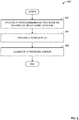
- FIG. 8 is a flowchart representing an example method 800 to produce the example static pressure taps 300, 400, 500, 600, 700 of FIGS. 3-7 , respectively.
- the example method 800 begins by providing a porous membrane 302, 602, 702 proximate an opening 110, 304 of an external surface 112 of the aircraft 100 within a static pressure tap 300, 600, 700 (block 802).
- the porous membrane 302, 602, 702 is placed or positioned to be flush with the external surface 112.
- the porous membrane 302, 602, 702 may be offset from the external surface 112 (e.g., by a distance of approximately 0 to 20 mm).
- the porous plug 402, 502, 604, 704 is provided proximate the opening 110 of the external surface 112 (block 804). In some other examples, the porous plug 402, 502, 604, 704 is positioned to be flush with the external surface 112. In some examples, the porous plug 402, 502, 604, 704 is coupled to the porous membrane 302, 602, 702.
- the pressure sensor 118 of the static pressure tap 300, 400, 500, 600, 700 is then calibrated (block 806) and the process ends.
Landscapes
- Physics & Mathematics (AREA)
- General Physics & Mathematics (AREA)
- Engineering & Computer Science (AREA)
- Aviation & Aerospace Engineering (AREA)
- Measuring Fluid Pressure (AREA)
Abstract
Description
- This disclosure relates generally to measuring static pressure measurements and, more particularly, to methods and apparatus to reduce static pressure measuring error.
- Typically, static pressure taps are utilized on vehicles, such as aircraft, to measure static pressure during various stages of operations (e.g., flight, idling on the ground, etc.). In particular, the static pressure may be measured to calculate a velocity of the aircraft. In some known examples, an opening of a static pressure tap of a vehicle is positioned along a surface across which air flows (e.g., the air flows perpendicular to the opening). A sensor is disposed within the vehicle at a defined distance from the opening so that the sensor is not substantially affected by a dynamic pressure component that can skew pressure measurements.
- It is with respect to these and other considerations that the disclosure made herein is presented.
- An example apparatus to measure static pressure includes a static pressure tap having a channel to define an external opening of a vehicle, where the channel extends through a pressure chamber to a pressure sensor disposed within, and a porous material disposed proximate the opening to reduce error in static pressure measurements.
- An example vehicle includes an external surface, a static pressure tap defining an opening of the external surface and a channel extending to a pressure chamber, a pressure sensor disposed within or proximate the pressure chamber, and a porous material proximate the opening and substantially covering the opening to reduce error associated with the pressure sensor.
- An example method of reducing error of a static pressure sensor of a vehicle includes providing porous material proximate an opening of a static pressure tap, where the opening at least partially defines an external surface of the vehicle, and where a channel extends from the opening to a pressure chamber having a pressure sensor disposed within.
-
-
FIG. 1A illustrates an aircraft in which the examples disclosed herein may be implemented. -
FIG. 1B is a detailed view depicting a known static pressure tap. -
FIG. 1C is a cross-sectional view of the known static pressure tap ofFIGS. 1A and 1B . -
FIG. 2 is a cross-sectional view representing pressure gradients of airflow across the known static pressure tap shown inFIGS. 1A- 1C . -
FIGS. 3-7 are cross-sectional views depicting example static pressure taps in accordance with the teachings of this disclosure. -
FIG. 8 is a flowchart representing an example method to produce the example static pressure taps shown inFIGS. 3-7 . - The figures are not to scale. Instead, to clarify multiple layers and regions, the thickness of the layers may be enlarged in the drawings. Wherever possible, the same reference numbers will be used throughout the drawing(s) and accompanying written description to refer to the same or like parts. As used in this patent, stating that any part (e.g., a layer, film, area, or plate) is in any way positioned on (e.g., positioned on, located on, disposed on, or formed on, etc.) another part, indicates that the referenced part is either in contact with the other part, or that the referenced part is above the other part with one or more intermediate part(s) located therebetween. Stating that any part is in contact with another part means that there is no intermediate part between the two parts.
- Static pressure taps are used on vehicles, such as aircraft, to measure a static pressure during various stages of vehicle operations (e.g., flight). In particular, the static pressure is typically measured by a static pressure tap to determine a velocity or airspeed of the vehicle. Thus, an accurate static pressure measurement is vital to make an accurate determination of velocity. Some known static pressure taps allow turbulent airflow to move into the static pressure tap, thereby adversely affecting an accuracy of a pressure sensor disposed within the static pressure tap. In other words, this turbulent airflow moving into the static pressure tap may skew measurements of the pressure sensor.
- The examples disclosed herein provide highly accurate static pressure measurements. In particular, the examples disclosed herein utilize porous material disposed proximate an opening of a channel that defines an external opening of a vehicle (e.g., an aircraft), where the channel extends to a pressure chamber having a pressure sensor disposed within. As a result, the porous material reduces error in static pressure measurements made by the sensor, thereby enabling highly accurate determinations of velocity and/or speed, for example.
- In some examples, the aforementioned porous material includes a membrane substantially covering the channel to define the external opening. Additionally or alternatively, the porous material includes a porous material plug. In some examples, a porous material plug is coupled to the membrane and extends in a direction generally towards the pressure chamber. Additionally or alternatively, a surface of the porous material is aligned (e.g., flush) with an external surface of a vehicle.
- In some examples, the porous material includes a woven fabric material to provide a flow resistance of the porous material between approximately 1 Rayl (centimeter gram second (CGS)) and approximately 1000 Rayl. In some examples, the porous material is composed of at least one of polyether ether ketone (PEEK), polyaryl ether ketone (PAEK) or polyether ketone ketone (PEKK). In some examples, the porous material includes a fabric membrane with a thickness between approximately 0.003 inches and 0.100 inches (between approximately 0.076 mm and 2.5 mm).
- As used herein, the term "static pressure tap" refers to components, an assembly and/or an integrated component that is used to measure a static pressure. As used herein, the term "porous material" refers to a material, composite material, a sponge-like material, a cloth-like material, a cellular material and/or material matrix with openings and/or cellular voids, which may be open or closed (e.g., external openings, internal openings, closed internal volumes, openings extending through a thickness, etc.). As used herein, stating that anything is "aligned" or "flush with" another means that first and second components are approximately between 0 to 10 millimeters (mm) from one another.
-
FIG. 1A illustrates anexample aircraft 100 in which the examples disclosed herein may be implemented. Theexample aircraft 100 includes afuselage 102 and wings 104 (e.g., a right wing and a left wing) extending laterally outward from thefuselage 102. Theexample aircraft 100 also includes a knownstatic pressure tap 106 that is positioned adjacent anose 108 of theaircraft 100. Alternatively, thestatic pressure tap 106 may be placed anywhere on thefuselage 102, thewings 104 or any appropriate outboard structure of theaircraft 100. - According to the illustrated example, the
static pressure tap 106 is positioned on theaircraft 100 such that air flows across (e.g., perpendicular to) thestatic pressure tap 106, but does not significantly enter the static pressure tap to mitigate skewing (e.g., contamination, biasing, etc.) by a dynamic pressure component of a static pressure measured at thestatic pressure tap 106. -
FIG. 1B is a detailed view of thestatic pressure tap 106 depicting anopening 110 of the knownstatic pressure tap 106 ofFIG. 1A . Theopening 110 of thestatic pressure tap 106 is a hole or opening that facilitates measurement of a static pressure component by a pressure sensor disposed within thestatic pressure tap 106. The opening 110 of the knownstatic pressure tap 106 is typically flush with an external surface (e.g., a wall, an external wall) 112 of theaircraft 100. -
FIG. 1C is a cross-sectional view of the knownstatic pressure tap 106 ofFIGS. 1A and 1B . Thestatic pressure tap 106 includes achannel 114 extending from theopening 110 to achamber 116. Further, apressure sensor 118 is disposed within thechamber 116 of thestatic pressure tap 106. -
FIG. 2 is a cross-sectional view illustrating pressure gradients ofexample airflow 202 across thestatic pressure tap 106 shown inFIGS. 1A-1C . Theexample airflow 202 flows substantially across theopening 110 of thestatic pressure tap 106. In some instances, the air may also at least partially flow into thechannel 114, thereby causingturbulent airflow 204 within thechannel 114 as well as thechamber 116, thereby negatively affecting measurements of thepressure sensor 118 by introducing dynamic pressure components. In turn, error associated with the static pressure measurement can affect a velocity or airspeed determination. -
FIG. 3 depicts an examplestatic pressure tap 300 to reduce error in static pressure measurements in accordance with the teachings of this disclosure. Thestatic pressure tap 300 of the illustrated example includes a porous membrane (e.g., a porous material membrane, a membrane made of a porous material) 302 positioned across anopening 304 of thestatic pressure tap 300 to reduce and/or substantially prevent turbulent airflow within achannel 306 and/or achamber 308. In some examples, the exampleporous membrane 302 is positioned such that a surface (e.g., an outer surface) 310 of theporous membrane 302 is flush and/or substantially aligned with theexternal surface 112 of theexample aircraft 100. - In some examples, the
porous membrane 302 is offset at a defineddistance 312 from (i.e., is not flush relative to) theexternal surface 112. For example, the porous membrane can be offset in a range from 0 to 20 mm. In such examples, theporous membrane 302 may be offset to facilitate manufacturing and/or installation of theporous membrane 302. The example offset dimensions are only examples and any appropriate offset dimension(s) may be utilized based on application, vehicle design and/or vehicle use, etc. - In some examples, the
porous membrane 302 is coupled to and/or installed on or within thestatic pressure tap 300 via an adhesive, an adhesive tape, a clamp, and/or any other suitable fastener. In some examples, thestatic pressure tap 300 may include a groove (e.g., an annular groove) 314 into which theporous membrane 302 is at least partially inserted during manufacturing. In some examples, theporous membrane 302 may be retrofitted to existing static pressure taps (e.g., thestatic pressure tap 106 is retrofitted with the porous membrane 302). - The
porous membrane 302 of the illustrated example may have a thickness between approximately 0.003 inches and 0.100 inches (between approximately 0.076 mm and 2.5 mm). However, theporous membrane 302 may have any appropriate thickness suitable to prevent turbulent airflow within thechannel 306 and/or thechamber 308 based on application need(s). In this example, theporous membrane 302 has a flow resistance between approximately 1 Rayl and approximately 1000 Rayl. However, any appropriate flow resistance may be utilized. Theporous membrane 302 may be any material having a suitable flow resistance and thickness. In some examples, theporous membrane 302 is selected and/or designed to satisfy other considerations, such as durability requirements, fire-resistance standards, etc. For example, theporous membrane 302 may include thermoplastic fibers, such as PEEK, PAEK and/or PEKK, etc. - To prevent a dynamic pressure component from negatively affecting measurement of a static pressure component, the
porous membrane 302 enables air to pass therethrough such that a pressure sensor (e.g., the pressure sensor 118) can accurately measure static pressure and/or a variation (or shift) of the static pressure. In other words, turbulent airflow, which has dynamic pressure components that can skew measurement(s) of the static pressure, is substantially prevented (e.g., fully prevented) from entering thechannel 306 and/or thechamber 308. -
FIG. 4 depicts another examplestatic pressure tap 400 in accordance with the teachings of this disclosure. According to the illustrated example ofFIG. 4 , the examplestatic pressure tap 400 is similar to the examplestatic pressure tap 300, but includes a porous plug (e.g., a porous material formed into a plug, a porous material plug, etc.) 402 instead of theporous material membrane 302. The exampleporous plug 402 is disposed adjacent anopening 403 of achannel 404 and extends towards achamber 406. The exampleporous plug 402 includes a surface (e.g., an outer surface, an upper surface) 408 that is substantially aligned with (e.g., flush with) theexternal surface 112 of theaircraft 100. - In some other examples, the
surface 408 of theporous plug 402 may be offset by adistance 410 from the external surface 112 (e.g., at an offset distance of 0 to 20 mm). In some examples, theporous plug 402 may be coupled to and/or installed in thestatic pressure tap 400 using an adhesive, adhesive tape, a clamp, or any other suitable fastener. In some examples, thestatic pressure tap 400 may include agroove 412 in which at least a portion (e.g., a tab or other protrusion) of theporous plug 402 is inserted during a manufacturing or assembly process. - In this example, the
porous plug 402 has a flow resistance between approximately 1 Rayl and approximately 1000 Rayl. In some examples, the thickness of theporous plug 402 corresponds to a porosity of the material. In particular, a length of theporous plug 402 that extends across the 404 may be varied based on the porosity, thereby enabling adjustability of the flow resistance in some examples. In some examples, theporous plug 402 is at least partially composed of PEEK, PAEK and/or PEKK, etc. -
FIG. 5 depicts another examplestatic pressure tap 500 in accordance with the teachings of this disclosure. In contrast to the examplestatic pressure tap 400, the examplestatic pressure tap 500 includes a porous plug (e.g., a porous material plug) 502 with aflange 504 that extends into achamber 506 of thestatic pressure tap 500. In this example, theflange 504 extends radially to contact aninner diameter 508 of thechamber 506. In some examples, a surface (e.g., an upper surface, an exterior surface, etc.) 510 of theporous plug 502 may be offset adistance 512 from the external surface 112 (e.g., an offset distance of approximately 0 to 20 mm). -
FIG. 6 depicts an examplestatic pressure tap 600 in accordance with the teachings of this disclosure. According to the illustrated example ofFIG. 6 , aporous membrane 602, which is similar to the exampleporous membrane 302 ofFIG. 3 , is implemented in conjunction with aporous plug 604, which is similar to the exampleporous plug 402 ofFIG. 4 . In this example, theporous membrane 602 of the illustrated example is coupled to theporous plug 604 and covers anopening 605 such that anouter surface 606 of theporous membrane 602 is flush with theexternal surface 112. In this example, theporous plug 604 is coupled to and aligned with a second surface (e.g., a bottom surface) 608 of theporous membrane 602 within achannel 610. - In some other examples, the
outer surface 606 of the exampleporous membrane 602 is offset adistance 612 from theexternal surface 112. In some examples, theporous membrane 602 and theporous plug 604 are made of different materials. -
FIG. 7 depicts an examplestatic pressure tap 700 in accordance with the teachings of this disclosure. According to the illustrated example ofFIG. 7 , aporous membrane 702, which similar to the exampleporous membrane 302 ofFIG. 3 , is coupled to aporous plug 704, which is similar to the exampleporous plug 502 ofFIG. 5 . Theporous membrane 702 includes an outer surface (e.g., an exterior surface, a top surface, etc.) 706 aligned with theexternal surface 112. In this example, theporous plug 704 is coupled to and aligned with an interior surface 708 (e.g., an interior surface, a bottom surface) of theporous membrane 702 within achannel 710. - In other examples, the
porous plug 704 is positioned within thechannel 710 and spaced a defined distance from theinterior surface 708 of theporous membrane 702. In some other examples, theouter surface 706 of the exampleporous membrane 702 is offset into thechannel 710 and away from the external surface 112 (e.g., offset internally by 0 to 20 mm). Additionally or alternatively, theporous plug 704 is spaced apart or separated from theinterior surface 708 of theporous membrane 702. Additionally or alternatively, theporous membrane 702 and theporous plug 704 are composed of different materials. -
FIG. 8 is a flowchart representing anexample method 800 to produce the example static pressure taps 300, 400, 500, 600, 700 ofFIGS. 3-7 , respectively. - The
example method 800 begins by providing aporous membrane opening external surface 112 of theaircraft 100 within astatic pressure tap porous membrane external surface 112. Alternatively, theporous membrane - Additionally or alternatively, the
porous plug opening 110 of the external surface 112 (block 804). In some other examples, theporous plug external surface 112. In some examples, theporous plug porous membrane - In some examples, the
pressure sensor 118 of thestatic pressure tap - Further, the disclosure comprises embodiments according to the following clauses:
- A1. An apparatus to measure static pressure, the apparatus comprising: a static pressure tap including a channel to define an external opening of a vehicle, the channel extending to a pressure chamber to have a pressure sensor disposed within; and porous material disposed proximate the external opening to reduce error in static pressure measurements.
- A2. The apparatus of clause A1, wherein the porous material includes a membrane substantially covering the channel to define the external opening.
- A3. The apparatus of clause A2, wherein the membrane is a fabric membrane with a thickness between approximately 0.003 inches and 0.100 inches (between approximately 0.076 mm and 2.5 mm).
- A4. The apparatus of clause A3, wherein the fabric membrane includes thermoplastic fibers.
- A5. The apparatus of clause A4, wherein the thermoplastic fibers are composed of one or more of PEEK, PAEK, or PEKK.
- A6. The apparatus of any of clauses A2 to A5 further including coupling a porous material plug to the membrane, the porous material to extend in a direction from the membrane towards the pressure chamber.
- A7. The apparatus of any of clauses A1 to A6, wherein a surface of the porous material is aligned with an external surface of a wall in which the static pressure tap is disposed.
- A8. The apparatus of any of clauses A1 to A7, wherein the porous material extends into the pressure chamber.
- A9. The apparatus of any of clauses A1 to A8, wherein the porous material includes a woven fabric material.
- A10. The apparatus of any of clauses A1 to A9, wherein a flow resistance of the porous material is between approximately 1 Rayl and approximately 1000 Rayl (centimeter gram second (CGS)).
- A11. The apparatus of any of clauses A1 to A10, wherein the porous material is composed of one or more of PEEK, PAEK, or PEKK.
- A12. The apparatus of any of clauses A1 to A11, wherein the vehicle is an aircraft.
- A13. A vehicle comprising: an external surface; a static pressure tap defining an opening of the external surface and a channel extending to a pressure chamber; a pressure sensor disposed within or proximate the pressure chamber; and porous material proximate the opening and substantially covering the opening to reduce error associated with the pressure sensor.
- A14. The vehicle of clause A13, wherein the porous material includes a woven fabric material.
- A15. The vehicle of clause A14, wherein the porous material includes a fabric membrane with a thickness between approximately 0.003 inches and 0.100 inches (between approximately 0.076 mm and 2.5 mm).
- A16. The vehicle of clause A15, wherein the fabric membrane includes thermoplastic fibers.
- A17. The vehicle of clause A16, wherein the thermoplastic fibers are composed of one or more of PEEK, PAEK, or PEKK.
- A18. The vehicle of any of clauses A13 to A17, wherein a surface of the porous material is aligned with the external surface.
- A19. The vehicle of any of clauses A13 to A18, wherein the porous material extends into the pressure chamber.
- A20. The vehicle of any of clauses A13 to A19, wherein a flow resistance of the porous material is between approximately 1 Rayl and approximately 1000 Rayl (centimeter gram second (CGS)).
- A21. A method of reducing error of a static pressure sensor of a vehicle, the method comprising providing porous material proximate an opening of a static pressure tap, the opening at least partially defined by an external surface of the vehicle and a channel extending from the opening to a pressure chamber having a pressure sensor disposed therein.
- A22. The method of clause A21, further comprising aligning an outer surface of the porous material with the external surface adjacent to the static pressure tap.
- A23. The method of clause A21 or A22, wherein the porous material is to be coupled to the static pressure tap using one or more of an adhesive, a clamp, or a fastener.
- A24. The method of any of clauses A21 to A23, wherein the porous material includes a membrane.
- A25. The method of clause A24, further including coupling a porous material plug to the membrane.
- From the foregoing, it will be appreciated that example methods, apparatus and articles of manufacture have been disclosed that significantly reduce static pressure measurement error in static pressure taps. As a result, vehicle velocity may be measured with high accuracy, for example.
- Although certain example methods, apparatus and articles of manufacture have been disclosed herein, the scope of coverage of this patent is not limited thereto. On the contrary, this patent covers all methods, apparatus and articles of manufacture fairly falling within the scope of the claims of this patent. While the examples disclosed herein are shown related to static pressure taps, the examples disclosed herein may be implemented for any appropriate pressure and/or flow measurement device or application. Accordingly, the examples disclosed herein may be implemented in spacecraft (e.g., used during reentry), watercraft, submersibles, as well as non-vehicle applications (e.g., aerodynamic applications, fins, turbines, windmills, wind tunnels, etc.).
Claims (15)
- An apparatus to measure static pressure, the apparatus comprising:a static pressure tap (300, 400, 500, 600, 700) including a channel (306, 404, 610, 710) defining an external opening, the channel extending to a pressure chamber for receiving a pressure sensor (118); andporous material disposed proximate the external opening to reduce error in static pressure measurements.
- The apparatus of claim 1, wherein the porous material includes a membrane (302, 602, 702) substantially covering the channel (306, 404, 610, 710) and defining the external opening.
- The apparatus of claim 2 further including coupling a porous material plug (402, 502) to the membrane (302, 602, 702), the porous material to extend in a direction from the membrane towards the pressure chamber.
- The apparatus of any preceding claim, wherein the porous material includes a woven fabric material.
- The apparatus of any preceding claim, wherein a flow resistance of the porous material is between approximately 1 Rayl and approximately 1000 Rayl (centimeter gram second (CGS)).
- The apparatus of any preceding claim, wherein the porous material is composed of one or more of PEEK, PAEK, or PEKK.
- The apparatus of any preceding claim, wherein the porous material is coupled to the static pressure tap (300, 400, 500, 600, 700) using one or more of an adhesive, a clamp, or a fastener.
- A vehicle comprising:an external surface;the apparatus of any preceding claim, wherein the external opening is an opening of the external surface; anda pressure sensor disposed within or proximate the pressure chamber.
- The vehicle of claim 8, wherein a surface of the porous material is aligned with the external surface.
- The vehicle of claim 8 or claim 9, wherein the vehicle is an aircraft (100).
- A method of modifying a static pressure sensor of a vehicle, optionally an aircraft, the method comprising providing porous material proximate an opening (304, 403, 605) of a static pressure tap (300, 400, 500, 600, 700), the opening at least partially defined by an external surface (112) of the vehicle and a channel (306, 404, 610, 710) extending from the opening to a pressure chamber having a pressure sensor (118) disposed therein.
- The method of claim 11, further comprising aligning an outer surface (408, 606, 706) of the porous material with the external surface (112) adjacent to the static pressure tap (300, 400, 500, 600, 700).
- The method of claim 11 or 12, further comprising coupling the porous material to the static pressure tap (300, 400, 500, 600, 700) using one or more of an adhesive, a clamp, or a fastener.
- The method of any of claims 11 to 13, wherein the porous material includes a membrane (302, 602, 702).
- The method of claim 14, further including coupling a porous material plug (402, 502) to the membrane (302, 602, 702).
Applications Claiming Priority (1)
| Application Number | Priority Date | Filing Date | Title |
|---|---|---|---|
| US15/786,341 US10807735B2 (en) | 2017-10-17 | 2017-10-17 | Methods and apparatus to reduce static pressure measuring error |
Publications (2)
| Publication Number | Publication Date |
|---|---|
| EP3473993A1 true EP3473993A1 (en) | 2019-04-24 |
| EP3473993B1 EP3473993B1 (en) | 2021-12-08 |
Family
ID=63762413
Family Applications (1)
| Application Number | Title | Priority Date | Filing Date |
|---|---|---|---|
| EP18198700.9A Not-in-force EP3473993B1 (en) | 2017-10-17 | 2018-10-04 | Methods and apparatus to reduce static pressure measuring error |
Country Status (4)
| Country | Link |
|---|---|
| US (1) | US10807735B2 (en) |
| EP (1) | EP3473993B1 (en) |
| CN (1) | CN109668677B (en) |
| IL (1) | IL262435B2 (en) |
Families Citing this family (1)
| Publication number | Priority date | Publication date | Assignee | Title |
|---|---|---|---|---|
| JP7396253B2 (en) * | 2020-11-12 | 2023-12-12 | 株式会社Sumco | Differential pressure measurement method |
Citations (3)
| Publication number | Priority date | Publication date | Assignee | Title |
|---|---|---|---|---|
| WO2013028220A1 (en) * | 2011-08-19 | 2013-02-28 | Aerovironment Inc. | Water resisitant aircraft pitot device |
| US9085665B1 (en) * | 2014-12-31 | 2015-07-21 | Vertera, Inc. | Method for producing porous material |
| US20170089792A1 (en) * | 2015-09-28 | 2017-03-30 | Merit Medical Systems, Inc. | Dampened pressure port |
Family Cites Families (19)
| Publication number | Priority date | Publication date | Assignee | Title |
|---|---|---|---|---|
| US3924464A (en) * | 1974-02-28 | 1975-12-09 | Carleton Controls Corp | Atmospheric pressure rate of change indicator |
| US4297900A (en) * | 1978-10-26 | 1981-11-03 | Brandt Industries, Inc. | Averaging pitot primary system |
| US4770032A (en) * | 1987-02-05 | 1988-09-13 | The United States Of America As Represented By The Administrator Of The National Aeronautics And Space Administration | Porous plug for reducing orifice induced pressure error in airfoils |
| US6940425B2 (en) * | 1997-12-02 | 2005-09-06 | James B. Frantz | Apparatus and method for determining information for aircraft |
| FR2802636B1 (en) | 1999-12-17 | 2002-03-22 | Thomson Csf Sextant | MULTIFUNCTIONAL PROBE FOR AIRCRAFT |
| US8128037B2 (en) * | 2009-01-19 | 2012-03-06 | The Boeing Company | Apparatus and method for passive purging of micro-perforated aerodynamic surfaces |
| CN102759335A (en) * | 2012-07-03 | 2012-10-31 | 湖北汽车工业学院 | Gas static pressure measuring head mechanism for car wheel detector |
| CN102777496B (en) * | 2012-08-09 | 2017-10-10 | 华锐风电科技(集团)股份有限公司 | Many oil pocket static pressure film thickness autocompensation installations and system |
| EP2735855A1 (en) * | 2012-11-21 | 2014-05-28 | Sensata Technologies, Inc. | A measuring device for measuring a physical quantity |
| WO2015066310A1 (en) * | 2013-10-30 | 2015-05-07 | Lime Instruments Llc | Sensor assembly for measuring dynamic pressure in reciprocating pumps |
| US9366555B2 (en) * | 2013-12-18 | 2016-06-14 | Lockheed Martin Corporation | Air data system |
| CN103759884B (en) * | 2014-01-29 | 2016-03-02 | 中国商用飞机有限责任公司 | Device and method for measuring static pressure of high-speed fluid in high-pressure pipeline |
| US9329197B2 (en) * | 2014-03-20 | 2016-05-03 | The Boeing Company | Method and apparatus for improved accuracy of static pressure measurement using pressure taps |
| US10227139B2 (en) * | 2015-03-23 | 2019-03-12 | Rosemount Aerospace Inc. | Heated air data probes |
| CN204479112U (en) * | 2015-04-14 | 2015-07-15 | 浙江海洋学院 | A kind of aviation pitot tube |
| FR3035209B1 (en) * | 2015-04-20 | 2018-10-05 | Thales | MULTIFUNCTION PROBE FOR PRIMARY REFERENCES FOR AIRCRAFT, MEASUREMENT SYSTEM, AIRCRAFT AND METHOD FOR OBTAINING PHYSICAL SIZES |
| CN205209690U (en) * | 2015-11-20 | 2016-05-04 | 沈阳黎明航空发动机(集团)有限责任公司 | Visit income formula and survey static pressure sensing head |
| US20180029719A1 (en) | 2016-07-28 | 2018-02-01 | The Boeing Company | Drag reducing liner assembly and methods of assembling the same |
| US10520524B1 (en) * | 2017-02-03 | 2019-12-31 | Aurora Flight Sciences Corporation | System and method for distributed airflow sensing |
-
2017
- 2017-10-17 US US15/786,341 patent/US10807735B2/en not_active Expired - Fee Related
-
2018
- 2018-10-04 EP EP18198700.9A patent/EP3473993B1/en not_active Not-in-force
- 2018-10-10 CN CN201811177546.9A patent/CN109668677B/en not_active Expired - Fee Related
- 2018-10-17 IL IL262435A patent/IL262435B2/en unknown
Patent Citations (3)
| Publication number | Priority date | Publication date | Assignee | Title |
|---|---|---|---|---|
| WO2013028220A1 (en) * | 2011-08-19 | 2013-02-28 | Aerovironment Inc. | Water resisitant aircraft pitot device |
| US9085665B1 (en) * | 2014-12-31 | 2015-07-21 | Vertera, Inc. | Method for producing porous material |
| US20170089792A1 (en) * | 2015-09-28 | 2017-03-30 | Merit Medical Systems, Inc. | Dampened pressure port |
Also Published As
| Publication number | Publication date |
|---|---|
| EP3473993B1 (en) | 2021-12-08 |
| CN109668677B (en) | 2022-05-13 |
| US20190112069A1 (en) | 2019-04-18 |
| IL262435A (en) | 2019-03-31 |
| US10807735B2 (en) | 2020-10-20 |
| CN109668677A (en) | 2019-04-23 |
| IL262435B1 (en) | 2023-04-01 |
| IL262435B2 (en) | 2023-08-01 |
Similar Documents
| Publication | Publication Date | Title |
|---|---|---|
| US20130145836A1 (en) | Probe for Measuring a Local Angle of Attack and Method Implementing Same | |
| US7150560B2 (en) | Device and method for determining total temperature for aircraft | |
| US10634530B2 (en) | Air data probe with improved performance at angle of attack operation | |
| US9366555B2 (en) | Air data system | |
| US20160305977A1 (en) | Multifunction probe for primary references for aircraft, associated measuring system, aircraft and method for obtaining physical quantities | |
| EP2743660B1 (en) | Air temperature sensor arrangement for a vehicle and method of measuring air temperature | |
| WO1994014075A1 (en) | Deployable probe combined with flush static port | |
| BRPI1104824B1 (en) | static door apparatus for an aircraft and static door assembly for an aircraft | |
| GB2541356A (en) | Moving-vane angle of attack probe | |
| AU2012101869A4 (en) | A convenient connection system for pressure measuring of the control surface | |
| EP3202664B1 (en) | Device for electrically grounding aircraft components mounted on a composite skin fuselage | |
| EP3473993A1 (en) | Methods and apparatus to reduce static pressure measuring error | |
| US11099096B2 (en) | Pressure measurement tool comprising a sheath for installation in a duct of an aircraft engine | |
| US20090000386A1 (en) | Fairing and installation methodology for sensor pressure belts | |
| EP3149494B1 (en) | Apparatus and method for assisting with fluid pressure measurement | |
| US20150268074A1 (en) | Method and Apparatus for Measuring Static Pressure | |
| US7350752B2 (en) | Fairing and installation methodology for sensor pressure belts | |
| US7510144B2 (en) | Elastic pre-deformed fairings for aircrafts | |
| US20210181038A1 (en) | Structure having a wall equipped with an optical sensor measuring device surrounded by a flexible envelope closely attached to the wall, and method for installing the device | |
| Rudnik | Experimental Analysis of Separation and Transition Phenomena for the DLR-F11 High Lift Configuration | |
| Rivers | Flight investigation of the effects of pressure-belt tubing size on measured pressure distributions | |
| Tokugawa et al. | Transition measurement system of experimental supersonic transport—NEXST-1 | |
| WO2007128053A1 (en) | A method of manufacturing a sensor for detecting surface cracks in a structure | |
| CN105447276B (en) | Helicopter lifting speed blending algorithm | |
| US1646903A (en) | Air-speed indicator |
Legal Events
| Date | Code | Title | Description |
|---|---|---|---|
| PUAI | Public reference made under article 153(3) epc to a published international application that has entered the european phase |
Free format text: ORIGINAL CODE: 0009012 |
|
| STAA | Information on the status of an ep patent application or granted ep patent |
Free format text: STATUS: REQUEST FOR EXAMINATION WAS MADE |
|
| 17P | Request for examination filed |
Effective date: 20181004 |
|
| AK | Designated contracting states |
Kind code of ref document: A1 Designated state(s): AL AT BE BG CH CY CZ DE DK EE ES FI FR GB GR HR HU IE IS IT LI LT LU LV MC MK MT NL NO PL PT RO RS SE SI SK SM TR |
|
| AX | Request for extension of the european patent |
Extension state: BA ME |
|
| GRAP | Despatch of communication of intention to grant a patent |
Free format text: ORIGINAL CODE: EPIDOSNIGR1 |
|
| STAA | Information on the status of an ep patent application or granted ep patent |
Free format text: STATUS: GRANT OF PATENT IS INTENDED |
|
| INTG | Intention to grant announced |
Effective date: 20200407 |
|
| GRAJ | Information related to disapproval of communication of intention to grant by the applicant or resumption of examination proceedings by the epo deleted |
Free format text: ORIGINAL CODE: EPIDOSDIGR1 |
|
| STAA | Information on the status of an ep patent application or granted ep patent |
Free format text: STATUS: REQUEST FOR EXAMINATION WAS MADE |
|
| INTC | Intention to grant announced (deleted) | ||
| STAA | Information on the status of an ep patent application or granted ep patent |
Free format text: STATUS: EXAMINATION IS IN PROGRESS |
|
| 17Q | First examination report despatched |
Effective date: 20201126 |
|
| GRAJ | Information related to disapproval of communication of intention to grant by the applicant or resumption of examination proceedings by the epo deleted |
Free format text: ORIGINAL CODE: EPIDOSDIGR1 |
|
| STAA | Information on the status of an ep patent application or granted ep patent |
Free format text: STATUS: GRANT OF PATENT IS INTENDED |
|
| GRAP | Despatch of communication of intention to grant a patent |
Free format text: ORIGINAL CODE: EPIDOSNIGR1 |
|
| INTG | Intention to grant announced |
Effective date: 20210604 |
|
| RIN1 | Information on inventor provided before grant (corrected) |
Inventor name: CHUCK, CHEN Inventor name: SATO, SHO |
|
| GRAS | Grant fee paid |
Free format text: ORIGINAL CODE: EPIDOSNIGR3 |
|
| GRAA | (expected) grant |
Free format text: ORIGINAL CODE: 0009210 |
|
| STAA | Information on the status of an ep patent application or granted ep patent |
Free format text: STATUS: THE PATENT HAS BEEN GRANTED |
|
| AK | Designated contracting states |
Kind code of ref document: B1 Designated state(s): AL AT BE BG CH CY CZ DE DK EE ES FI FR GB GR HR HU IE IS IT LI LT LU LV MC MK MT NL NO PL PT RO RS SE SI SK SM TR |
|
| REG | Reference to a national code |
Ref country code: GB Ref legal event code: FG4D |
|
| REG | Reference to a national code |
Ref country code: AT Ref legal event code: REF Ref document number: 1454121 Country of ref document: AT Kind code of ref document: T Effective date: 20211215 Ref country code: CH Ref legal event code: EP |
|
| REG | Reference to a national code |
Ref country code: DE Ref legal event code: R096 Ref document number: 602018027803 Country of ref document: DE |
|
| REG | Reference to a national code |
Ref country code: IE Ref legal event code: FG4D |
|
| REG | Reference to a national code |
Ref country code: LT Ref legal event code: MG9D |
|
| REG | Reference to a national code |
Ref country code: NL Ref legal event code: MP Effective date: 20211208 |
|
| PG25 | Lapsed in a contracting state [announced via postgrant information from national office to epo] |
Ref country code: RS Free format text: LAPSE BECAUSE OF FAILURE TO SUBMIT A TRANSLATION OF THE DESCRIPTION OR TO PAY THE FEE WITHIN THE PRESCRIBED TIME-LIMIT Effective date: 20211208 Ref country code: LT Free format text: LAPSE BECAUSE OF FAILURE TO SUBMIT A TRANSLATION OF THE DESCRIPTION OR TO PAY THE FEE WITHIN THE PRESCRIBED TIME-LIMIT Effective date: 20211208 Ref country code: FI Free format text: LAPSE BECAUSE OF FAILURE TO SUBMIT A TRANSLATION OF THE DESCRIPTION OR TO PAY THE FEE WITHIN THE PRESCRIBED TIME-LIMIT Effective date: 20211208 Ref country code: BG Free format text: LAPSE BECAUSE OF FAILURE TO SUBMIT A TRANSLATION OF THE DESCRIPTION OR TO PAY THE FEE WITHIN THE PRESCRIBED TIME-LIMIT Effective date: 20220308 |
|
| REG | Reference to a national code |
Ref country code: AT Ref legal event code: MK05 Ref document number: 1454121 Country of ref document: AT Kind code of ref document: T Effective date: 20211208 |
|
| PG25 | Lapsed in a contracting state [announced via postgrant information from national office to epo] |
Ref country code: SE Free format text: LAPSE BECAUSE OF FAILURE TO SUBMIT A TRANSLATION OF THE DESCRIPTION OR TO PAY THE FEE WITHIN THE PRESCRIBED TIME-LIMIT Effective date: 20211208 Ref country code: NO Free format text: LAPSE BECAUSE OF FAILURE TO SUBMIT A TRANSLATION OF THE DESCRIPTION OR TO PAY THE FEE WITHIN THE PRESCRIBED TIME-LIMIT Effective date: 20220308 Ref country code: LV Free format text: LAPSE BECAUSE OF FAILURE TO SUBMIT A TRANSLATION OF THE DESCRIPTION OR TO PAY THE FEE WITHIN THE PRESCRIBED TIME-LIMIT Effective date: 20211208 Ref country code: HR Free format text: LAPSE BECAUSE OF FAILURE TO SUBMIT A TRANSLATION OF THE DESCRIPTION OR TO PAY THE FEE WITHIN THE PRESCRIBED TIME-LIMIT Effective date: 20211208 Ref country code: GR Free format text: LAPSE BECAUSE OF FAILURE TO SUBMIT A TRANSLATION OF THE DESCRIPTION OR TO PAY THE FEE WITHIN THE PRESCRIBED TIME-LIMIT Effective date: 20220309 Ref country code: ES Free format text: LAPSE BECAUSE OF FAILURE TO SUBMIT A TRANSLATION OF THE DESCRIPTION OR TO PAY THE FEE WITHIN THE PRESCRIBED TIME-LIMIT Effective date: 20211208 |
|
| PG25 | Lapsed in a contracting state [announced via postgrant information from national office to epo] |
Ref country code: NL Free format text: LAPSE BECAUSE OF FAILURE TO SUBMIT A TRANSLATION OF THE DESCRIPTION OR TO PAY THE FEE WITHIN THE PRESCRIBED TIME-LIMIT Effective date: 20211208 |
|
| PG25 | Lapsed in a contracting state [announced via postgrant information from national office to epo] |
Ref country code: SM Free format text: LAPSE BECAUSE OF FAILURE TO SUBMIT A TRANSLATION OF THE DESCRIPTION OR TO PAY THE FEE WITHIN THE PRESCRIBED TIME-LIMIT Effective date: 20211208 Ref country code: SK Free format text: LAPSE BECAUSE OF FAILURE TO SUBMIT A TRANSLATION OF THE DESCRIPTION OR TO PAY THE FEE WITHIN THE PRESCRIBED TIME-LIMIT Effective date: 20211208 Ref country code: RO Free format text: LAPSE BECAUSE OF FAILURE TO SUBMIT A TRANSLATION OF THE DESCRIPTION OR TO PAY THE FEE WITHIN THE PRESCRIBED TIME-LIMIT Effective date: 20211208 Ref country code: PT Free format text: LAPSE BECAUSE OF FAILURE TO SUBMIT A TRANSLATION OF THE DESCRIPTION OR TO PAY THE FEE WITHIN THE PRESCRIBED TIME-LIMIT Effective date: 20220408 Ref country code: EE Free format text: LAPSE BECAUSE OF FAILURE TO SUBMIT A TRANSLATION OF THE DESCRIPTION OR TO PAY THE FEE WITHIN THE PRESCRIBED TIME-LIMIT Effective date: 20211208 Ref country code: CZ Free format text: LAPSE BECAUSE OF FAILURE TO SUBMIT A TRANSLATION OF THE DESCRIPTION OR TO PAY THE FEE WITHIN THE PRESCRIBED TIME-LIMIT Effective date: 20211208 |
|
| PG25 | Lapsed in a contracting state [announced via postgrant information from national office to epo] |
Ref country code: PL Free format text: LAPSE BECAUSE OF FAILURE TO SUBMIT A TRANSLATION OF THE DESCRIPTION OR TO PAY THE FEE WITHIN THE PRESCRIBED TIME-LIMIT Effective date: 20211208 Ref country code: AT Free format text: LAPSE BECAUSE OF FAILURE TO SUBMIT A TRANSLATION OF THE DESCRIPTION OR TO PAY THE FEE WITHIN THE PRESCRIBED TIME-LIMIT Effective date: 20211208 |
|
| REG | Reference to a national code |
Ref country code: DE Ref legal event code: R097 Ref document number: 602018027803 Country of ref document: DE |
|
| PG25 | Lapsed in a contracting state [announced via postgrant information from national office to epo] |
Ref country code: IS Free format text: LAPSE BECAUSE OF FAILURE TO SUBMIT A TRANSLATION OF THE DESCRIPTION OR TO PAY THE FEE WITHIN THE PRESCRIBED TIME-LIMIT Effective date: 20220408 |
|
| PLBE | No opposition filed within time limit |
Free format text: ORIGINAL CODE: 0009261 |
|
| STAA | Information on the status of an ep patent application or granted ep patent |
Free format text: STATUS: NO OPPOSITION FILED WITHIN TIME LIMIT |
|
| PG25 | Lapsed in a contracting state [announced via postgrant information from national office to epo] |
Ref country code: DK Free format text: LAPSE BECAUSE OF FAILURE TO SUBMIT A TRANSLATION OF THE DESCRIPTION OR TO PAY THE FEE WITHIN THE PRESCRIBED TIME-LIMIT Effective date: 20211208 Ref country code: AL Free format text: LAPSE BECAUSE OF FAILURE TO SUBMIT A TRANSLATION OF THE DESCRIPTION OR TO PAY THE FEE WITHIN THE PRESCRIBED TIME-LIMIT Effective date: 20211208 |
|
| 26N | No opposition filed |
Effective date: 20220909 |
|
| PG25 | Lapsed in a contracting state [announced via postgrant information from national office to epo] |
Ref country code: SI Free format text: LAPSE BECAUSE OF FAILURE TO SUBMIT A TRANSLATION OF THE DESCRIPTION OR TO PAY THE FEE WITHIN THE PRESCRIBED TIME-LIMIT Effective date: 20211208 |
|
| PG25 | Lapsed in a contracting state [announced via postgrant information from national office to epo] |
Ref country code: MC Free format text: LAPSE BECAUSE OF FAILURE TO SUBMIT A TRANSLATION OF THE DESCRIPTION OR TO PAY THE FEE WITHIN THE PRESCRIBED TIME-LIMIT Effective date: 20211208 Ref country code: IT Free format text: LAPSE BECAUSE OF FAILURE TO SUBMIT A TRANSLATION OF THE DESCRIPTION OR TO PAY THE FEE WITHIN THE PRESCRIBED TIME-LIMIT Effective date: 20211208 |
|
| REG | Reference to a national code |
Ref country code: CH Ref legal event code: PL |
|
| P01 | Opt-out of the competence of the unified patent court (upc) registered |
Effective date: 20230516 |
|
| REG | Reference to a national code |
Ref country code: BE Ref legal event code: MM Effective date: 20221031 |
|
| PG25 | Lapsed in a contracting state [announced via postgrant information from national office to epo] |
Ref country code: LU Free format text: LAPSE BECAUSE OF NON-PAYMENT OF DUE FEES Effective date: 20221004 |
|
| PG25 | Lapsed in a contracting state [announced via postgrant information from national office to epo] |
Ref country code: LI Free format text: LAPSE BECAUSE OF NON-PAYMENT OF DUE FEES Effective date: 20221031 Ref country code: CH Free format text: LAPSE BECAUSE OF NON-PAYMENT OF DUE FEES Effective date: 20221031 |
|
| PG25 | Lapsed in a contracting state [announced via postgrant information from national office to epo] |
Ref country code: BE Free format text: LAPSE BECAUSE OF NON-PAYMENT OF DUE FEES Effective date: 20221031 |
|
| PG25 | Lapsed in a contracting state [announced via postgrant information from national office to epo] |
Ref country code: IE Free format text: LAPSE BECAUSE OF NON-PAYMENT OF DUE FEES Effective date: 20221004 |
|
| PGFP | Annual fee paid to national office [announced via postgrant information from national office to epo] |
Ref country code: GB Payment date: 20231027 Year of fee payment: 6 |
|
| PGFP | Annual fee paid to national office [announced via postgrant information from national office to epo] |
Ref country code: FR Payment date: 20231025 Year of fee payment: 6 Ref country code: DE Payment date: 20231027 Year of fee payment: 6 |
|
| PG25 | Lapsed in a contracting state [announced via postgrant information from national office to epo] |
Ref country code: HU Free format text: LAPSE BECAUSE OF FAILURE TO SUBMIT A TRANSLATION OF THE DESCRIPTION OR TO PAY THE FEE WITHIN THE PRESCRIBED TIME-LIMIT; INVALID AB INITIO Effective date: 20181004 |
|
| PG25 | Lapsed in a contracting state [announced via postgrant information from national office to epo] |
Ref country code: CY Free format text: LAPSE BECAUSE OF FAILURE TO SUBMIT A TRANSLATION OF THE DESCRIPTION OR TO PAY THE FEE WITHIN THE PRESCRIBED TIME-LIMIT Effective date: 20211208 |
|
| PG25 | Lapsed in a contracting state [announced via postgrant information from national office to epo] |
Ref country code: MK Free format text: LAPSE BECAUSE OF FAILURE TO SUBMIT A TRANSLATION OF THE DESCRIPTION OR TO PAY THE FEE WITHIN THE PRESCRIBED TIME-LIMIT Effective date: 20211208 |
|
| PG25 | Lapsed in a contracting state [announced via postgrant information from national office to epo] |
Ref country code: MT Free format text: LAPSE BECAUSE OF FAILURE TO SUBMIT A TRANSLATION OF THE DESCRIPTION OR TO PAY THE FEE WITHIN THE PRESCRIBED TIME-LIMIT Effective date: 20211208 |
|
| REG | Reference to a national code |
Ref country code: DE Ref legal event code: R119 Ref document number: 602018027803 Country of ref document: DE |
|
| GBPC | Gb: european patent ceased through non-payment of renewal fee |
Effective date: 20241004 |
|
| PG25 | Lapsed in a contracting state [announced via postgrant information from national office to epo] |
Ref country code: DE Free format text: LAPSE BECAUSE OF NON-PAYMENT OF DUE FEES Effective date: 20250501 |
|
| PG25 | Lapsed in a contracting state [announced via postgrant information from national office to epo] |
Ref country code: GB Free format text: LAPSE BECAUSE OF NON-PAYMENT OF DUE FEES Effective date: 20241004 |
|
| PG25 | Lapsed in a contracting state [announced via postgrant information from national office to epo] |
Ref country code: FR Free format text: LAPSE BECAUSE OF NON-PAYMENT OF DUE FEES Effective date: 20241031 |
|
| PG25 | Lapsed in a contracting state [announced via postgrant information from national office to epo] |
Ref country code: TR Free format text: LAPSE BECAUSE OF FAILURE TO SUBMIT A TRANSLATION OF THE DESCRIPTION OR TO PAY THE FEE WITHIN THE PRESCRIBED TIME-LIMIT Effective date: 20211208 |