EP3473965A1 - Armour assembly - Google Patents
Armour assembly Download PDFInfo
- Publication number
- EP3473965A1 EP3473965A1 EP17197575.8A EP17197575A EP3473965A1 EP 3473965 A1 EP3473965 A1 EP 3473965A1 EP 17197575 A EP17197575 A EP 17197575A EP 3473965 A1 EP3473965 A1 EP 3473965A1
- Authority
- EP
- European Patent Office
- Prior art keywords
- armour
- armour assembly
- assembly according
- gyroid structure
- panel
- Prior art date
- Legal status (The legal status is an assumption and is not a legal conclusion. Google has not performed a legal analysis and makes no representation as to the accuracy of the status listed.)
- Ceased
Links
- 238000004519 manufacturing process Methods 0.000 claims abstract description 3
- 239000000463 material Substances 0.000 claims description 19
- 239000000945 filler Substances 0.000 claims description 7
- OKTJSMMVPCPJKN-UHFFFAOYSA-N Carbon Chemical compound [C] OKTJSMMVPCPJKN-UHFFFAOYSA-N 0.000 claims description 5
- 239000006260 foam Substances 0.000 claims description 4
- 239000007788 liquid Substances 0.000 claims description 4
- 239000000919 ceramic Substances 0.000 claims description 3
- 229910052751 metal Inorganic materials 0.000 claims description 3
- 239000002184 metal Substances 0.000 claims description 3
- 229910052752 metalloid Inorganic materials 0.000 claims description 3
- 150000002738 metalloids Chemical class 0.000 claims description 3
- 229910052799 carbon Inorganic materials 0.000 claims description 2
- 239000002131 composite material Substances 0.000 claims description 2
- 230000008878 coupling Effects 0.000 claims description 2
- 238000010168 coupling process Methods 0.000 claims description 2
- 238000005859 coupling reaction Methods 0.000 claims description 2
- 229920001971 elastomer Polymers 0.000 claims description 2
- 239000000806 elastomer Substances 0.000 claims description 2
- 229910001092 metal group alloy Inorganic materials 0.000 claims description 2
- 229920000642 polymer Polymers 0.000 claims description 2
- 238000007639 printing Methods 0.000 claims description 2
- 238000000034 method Methods 0.000 description 5
- 238000010146 3D printing Methods 0.000 description 4
- 238000011960 computer-aided design Methods 0.000 description 3
- 230000000694 effects Effects 0.000 description 3
- 229910021389 graphene Inorganic materials 0.000 description 3
- 230000001133 acceleration Effects 0.000 description 2
- 210000003027 ear inner Anatomy 0.000 description 2
- 229910000760 Hardened steel Inorganic materials 0.000 description 1
- 229910000831 Steel Inorganic materials 0.000 description 1
- 230000003466 anti-cipated effect Effects 0.000 description 1
- 238000011161 development Methods 0.000 description 1
- 239000012530 fluid Substances 0.000 description 1
- 150000002739 metals Chemical class 0.000 description 1
- 238000012986 modification Methods 0.000 description 1
- 230000004048 modification Effects 0.000 description 1
- 230000035515 penetration Effects 0.000 description 1
- 238000012545 processing Methods 0.000 description 1
- 239000004576 sand Substances 0.000 description 1
- 239000007787 solid Substances 0.000 description 1
- 239000010959 steel Substances 0.000 description 1
- 230000008719 thickening Effects 0.000 description 1
- XLYOFNOQVPJJNP-UHFFFAOYSA-N water Substances O XLYOFNOQVPJJNP-UHFFFAOYSA-N 0.000 description 1
Images


Classifications
-
- F—MECHANICAL ENGINEERING; LIGHTING; HEATING; WEAPONS; BLASTING
- F41—WEAPONS
- F41H—ARMOUR; ARMOURED TURRETS; ARMOURED OR ARMED VEHICLES; MEANS OF ATTACK OR DEFENCE, e.g. CAMOUFLAGE, IN GENERAL
- F41H5/00—Armour; Armour plates
- F41H5/02—Plate construction
- F41H5/023—Armour plate, or auxiliary armour plate mounted at a distance of the main armour plate, having cavities at its outer impact surface, or holes, for deflecting the projectile
Definitions
- the present invention relates to an armour assembly.
- Vehicles such as military vehicles, sometimes require armour to protect the vehicle and its occupants from harm when the vehicle is in a hostile environment, for example.
- the type of armour used on a vehicle will primarily depend on the type of anticipated threat, but consideration will also need to be given to the effect of the armour on the vehicle's performance (e.g. the effect on speed and/or manoeuvrability due to the weight of the armour).
- Appliqué armour is routinely used to provide a sacrificial or readily replaceable piece of armour, which defeats certain threats very effectively, but may not provide high levels of general protection from all forms of hazard threats likely to be encountered.
- Perforated armour plates to protect against kinetic energy projectiles such as ballistic firearm ammunition.
- Perforated armour comprises a sheet of armour, such as hardened steel, with a plurality of holes therethrough.
- perforated armour can provide improved protection against ballistic projectiles. This improved protection at least partly arises from the increase in edged surfaces (i.e. around each hole) that are presented to an incoming ballistic projectile.
- an incoming ballistic projectile is statistically more likely to impact (or, at least, partially impact) on one of the edged surfaces and thereby experience a higher pressure than it would if it was to impact on a flat surface (such as unperforated armour).
- the increase of pressure increases the likelihood of the ballistic projectile disintegrating on impact or being deflected and thereby reducing its energy, and thus its ability to penetrate the armour.
- EP-A-0209221 The State of Israel Ministry of Defense Rafael - Armament Development Authority.
- the armour assembly of EP-A-0209221 is specifically designed for armoured vehicles and comprises a perforated armour plate mounted to a conventional armour plate and spaced therefrom.
- armour increases a vehicle's defences against ballistic projectiles
- the added weight can impair the vehicle's ability to manoeuvre and travel at its optimal or preferred speed or acceleration rate, even when lighter perforated armour is used. This is a particular problem when considering vehicles that may be travelling in and out of known safe areas where no or less protection is required, or when travelling in areas where it is undesirable to compromise the vehicle's speed, acceleration or manoeuvrability. In these cases, the armour must be removed from the vehicle which is an onerous task that requires the personnel to be in possession of the appropriate tools.
- an armour assembly comprising one or more panels, wherein at least one of the one or more panels comprises a gyroid structure.
- Gyroid structures tend to be lightweight and of low density yet have a high tensile strength.
- the armour assembly can maintain its property of high resistance to penetration and blast, while being made more lightweight to enable a vehicle to travel faster or a person wearing the armour assembly to be less prone to fatigue.
- the gyroid structure may be manufactured using a three-dimensional image forming apparatus.
- the panel disposed adjacent to the panel comprising the gyroid structure may comprise an armour plate.
- the panel disposed adjacent to the panel comprising the gyroid structure may comprise KevlarTM.
- the armour assembly may comprise the primary armour of a vehicle.
- the gyroid structure may be manufactured from one of a metal, a metal alloy, a composite, a polymer, an elastomer, metalloid and a ceramic.
- the metalloid may be carbon, such as graphene.
- the gyroid structure may be used to turn bi-dimensional materials, such as graphene, into a three-dimensional structural material having low density and yet retaining high tensile strength.
- the thickness of the surface of the gyroid structure may be between 0.5 mm and 10 mm. Preferably, the thickness may be between 1 mm and 5 mm. Even more preferably, the thickness may be 2 mm.
- the gyroid structure may be encapsulated in an encapsulating structure.
- the encapsulating structure may be formed using the three-dimensional printing apparatus.
- the gyroid structure may comprise a plurality of cavities which may comprise a filler material.
- the filler material may comprise a particulate, liquid or foam.
- the armour assembly may further comprise brackets for coupling the armour assembly to the body of a vehicle, vessel or craft.
- the brackets may be manufactured using the three-dimensional image forming apparatus.
- the gyroid structure, brackets and encapsulating structure may be formed as part of the same processing step.
- a body-worn armour comprising the armour assembly of the first aspect.
- an armoured vehicle having a main body, wherein the main body comprises the armour assembly according to the first aspect.
- the armour assembly according to the first aspect may be coupled to the main body of the vehicle using brackets.
- a method of manufacturing an armour assembly comprising three-dimensionally printing at least one panel having a gyroid structure.
- the method may comprise encapsulating the gyroid structure.
- the method may further comprise attaching the panel having the gyroid structure to at least one further panel.
- the method may comprise forming brackets on the panel having the gyroid structure.
- Embodiments of the present invention provide an armour assembly comprising a gyroid structure. This tends to reduce the weight of the armour assembly without compromising its ballistic or blast protection for occupants of a vehicle, vessel or craft.
- the armour assembly can also be incorporated into a body-worn armour such a bulletproof or stab vest.
- Figure 1 shows a perspective view of a gyroid structure 1.
- the gyroid structure 1 separates space into two oppositely congruent labyrinths of passages.
- the gyroid structure 1 has space group la3d. Channels run through the gyroid labyrinths in the (100) and (111) directions; passages emerge at 70.5 degree angles to any given channel as it is traversed, the direction at which they do so gyrating down the channel, giving rise to the name "gyroid".
- the gyroid structure 1 contains neither straight lines nor planar symmetries.
- the gyroid structure 1 may be printed using a 3D printer.
- the gyroid structure 1 is formed of graphene.
- the thickness of the surface of the gyroid structure is 2 mm.
- the gyroid structure 1 may be formed of any suitable material, and has a thickness of between 0.5 mm and 10 mm.
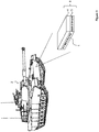
- Figure 2 shows an armoured vehicle 2 having a main body comprising a hull and a turret.
- the main body comprises an armour assembly 8, formed from a series of armour panels 3-7.
- Each panel 3-7 may have a thickness of between 100 mm and 500 mm.
- At least one of the panels 3-7 is an armour plate.
- Each panel 3-7 comprises an armour material.
- the armour material in each panel 3-7 is different to the armour material in the other panels 3-7.
- the armour assembly 8 has 5 panels 3-7.
- the first panel 3 may be, for example, an armour plate made of steel.
- the second panel 4 may be, for example, formed of a honeycomb structure made from ceramic.
- the third panel 5 may, for example, be filled with the gyroid structure 1 shown in Figure 1 .
- the fourth panel 6 may be, for example, filled with a liquid.
- the fifth panel 7 may be, for example, filled with a foam. It would be appreciated that the panels 3-7 could be arranged in any order and could be formed of different armour materials than those described above.
- the first panel 3 may instead comprise the gyroid structure 1.
- the armour material of at least one of the panels 5 comprises the gyroid structure 1 shown in Figure 1 .
- the panel 5 having the gyroid structure 1 may be encapsulated.
- the gyroid structure 1 is encapsulated using the same material as used to form the gyroid structure 1.
- the gyroid structure 1 and encapsulating structure may be formed in a single three-dimensional printing process.
- Armour material of the other panels 3-7 in the armour assembly 8 is selected from known armour materials.
- the gyroid structure 1 includes cavities. In some embodiments, the cavities are filled with a filler. Use of the filler tends to provide an improved armour effect.
- the fillers may include liquids (such as shear thickening fluid and water), foams and particulates (such as sand, metals and uncured 3D printing material).
- the armour assembly 8 shown in Figure 2 is a section through the front of the hull of the vehicle 2, the armour assembly 8 may form the main body of any part of the vehicle 2.
- the armour assembly 8 may form the top surface of the turret in order to protect the occupants from aerial attack or indirect fire.
- the armour assembly 8 may form the rear of the hull to protect the engine compartment.
- the armour assembly 8 may form the side skirts of the vehicle 2 to protect the tracks and bogies.
- the armour assembly 8 is applied to the vehicle 2 as appliqué armour.
- the armour assembly 8 includes brackets for attaching the armour assembly 8 to the main body of the vehicle 2.
- the gyroid structure 1 (and, in some embodiments, the encapsulating structure) and brackets are formed in a single three-dimensional printing process.
- CAD computer aided design
- a surface shell i.e. an encapsulating structure surrounding the gyroid structure 1 with built-in brackets can be incorporated in to the CAD file and printed as one unit.
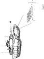
- Figure 3 shows another embodiment of the present invention.
- the armour assembly 8 includes only two panels 4, 5.
- One of the panels 5 comprises the gyroid structure 1 shown in Figure 1 .
- Brackets may be fixed to one of the outer panels 4, 5 in order to couple the armour assembly 8 to the vehicle 2.
- the armour assembly 8 may form the primary armour of the vehicle 2.
- Figure 4 shows another embodiment of the present invention.
- the armour assembly 8 includes only a single panel 5.
- the panel 5 comprises the gyroid structure 1 shown in Figure 1 .
- the gyroid structure 1 may be encapsulated in a material different to that of the gyroid structure 1.
- the gyroid structure 1 may be encapsulated in the same material as the gyroid structure 1.
- the panel 5 may further include brackets for fixing the armour assembly 8 to the vehicle 2.
- the armour assembly 8 may form the primary armour of the vehicle 2.
- Figures 3 and 4 show only examples of an armour assembly 8 structure, and in other embodiments the armour assembly 8 includes more than the number of panels 3-7 shown in these Figures.
- the armour assembly 8 may be incorporated into the main body of a wheeled vehicle, a vessel or an aircraft, such as a ship or helicopter.
- the armour assembly 8 is used in a garment such as a bulletproof vest or a stab vest.
- the armour material of at least one of the armour panels 3-7 comprises KevlarTM.
Landscapes
- Engineering & Computer Science (AREA)
- General Engineering & Computer Science (AREA)
- Aiming, Guidance, Guns With A Light Source, Armor, Camouflage, And Targets (AREA)
Abstract
The present invention provides an armour assembly comprising one or more panels, wherein at least one of the one or more panels comprises a gyroid structure. The present invention also provides an armoured vehicle, a body-worn armour and a method of manufacturing an armour assembly.
Description
- The present invention relates to an armour assembly.
- Vehicles, such as military vehicles, sometimes require armour to protect the vehicle and its occupants from harm when the vehicle is in a hostile environment, for example. The type of armour used on a vehicle will primarily depend on the type of anticipated threat, but consideration will also need to be given to the effect of the armour on the vehicle's performance (e.g. the effect on speed and/or manoeuvrability due to the weight of the armour).
- Appliqué armour is routinely used to provide a sacrificial or readily replaceable piece of armour, which defeats certain threats very effectively, but may not provide high levels of general protection from all forms of hazard threats likely to be encountered.
- It is known to use perforated armour plates to protect against kinetic energy projectiles such as ballistic firearm ammunition. Perforated armour comprises a sheet of armour, such as hardened steel, with a plurality of holes therethrough. In addition to being less heavy than solid armour (due to the presence of the holes), perforated armour can provide improved protection against ballistic projectiles. This improved protection at least partly arises from the increase in edged surfaces (i.e. around each hole) that are presented to an incoming ballistic projectile. With an increase in edged surfaces, an incoming ballistic projectile is statistically more likely to impact (or, at least, partially impact) on one of the edged surfaces and thereby experience a higher pressure than it would if it was to impact on a flat surface (such as unperforated armour). The increase of pressure increases the likelihood of the ballistic projectile disintegrating on impact or being deflected and thereby reducing its energy, and thus its ability to penetrate the armour.
- An example of an armour assembly comprising perforated armour is described in
EP-A-0209221 (The State of Israel Ministry of Defence Rafael - Armament Development Authority). The armour assembly ofEP-A-0209221 is specifically designed for armoured vehicles and comprises a perforated armour plate mounted to a conventional armour plate and spaced therefrom. - As mentioned above, whilst the addition of armour increases a vehicle's defences against ballistic projectiles, the added weight can impair the vehicle's ability to manoeuvre and travel at its optimal or preferred speed or acceleration rate, even when lighter perforated armour is used. This is a particular problem when considering vehicles that may be travelling in and out of known safe areas where no or less protection is required, or when travelling in areas where it is undesirable to compromise the vehicle's speed, acceleration or manoeuvrability. In these cases, the armour must be removed from the vehicle which is an onerous task that requires the personnel to be in possession of the appropriate tools.
- It is an object of the present invention to provide an armour assembly that overcomes the problems associated with the prior art.
- According to a first aspect of the present invention, there is provided an armour assembly comprising one or more panels, wherein at least one of the one or more panels comprises a gyroid structure.
- Gyroid structures tend to be lightweight and of low density yet have a high tensile strength. By incorporating such a structure into an armour assembly, the armour assembly can maintain its property of high resistance to penetration and blast, while being made more lightweight to enable a vehicle to travel faster or a person wearing the armour assembly to be less prone to fatigue.
- The gyroid structure may be manufactured using a three-dimensional image forming apparatus.
- There may be at least one panel disposed adjacent to the panel comprising the gyroid structure.
- The panel disposed adjacent to the panel comprising the gyroid structure may comprise an armour plate. Alternatively, the panel disposed adjacent to the panel comprising the gyroid structure may comprise Kevlar™.
- The armour assembly may comprise the primary armour of a vehicle.
- The gyroid surface can be trigonometrically approximated by the equation:

- The gyroid structure may be manufactured from one of a metal, a metal alloy, a composite, a polymer, an elastomer, metalloid and a ceramic. The metalloid may be carbon, such as graphene.
- The gyroid structure may be used to turn bi-dimensional materials, such as graphene, into a three-dimensional structural material having low density and yet retaining high tensile strength.
- The thickness of the surface of the gyroid structure may be between 0.5 mm and 10 mm. Preferably, the thickness may be between 1 mm and 5 mm. Even more preferably, the thickness may be 2 mm.
- The gyroid structure may be encapsulated in an encapsulating structure. The encapsulating structure may be formed using the three-dimensional printing apparatus.
The gyroid structure may comprise a plurality of cavities which may comprise a filler material. The filler material may comprise a particulate, liquid or foam. - The armour assembly may further comprise brackets for coupling the armour assembly to the body of a vehicle, vessel or craft. The brackets may be manufactured using the three-dimensional image forming apparatus. The gyroid structure, brackets and encapsulating structure may be formed as part of the same processing step.
- According to a second aspect of the present invention, there is provided a body-worn armour comprising the armour assembly of the first aspect.
- According to a third aspect of the present invention, there is provided an armoured vehicle having a main body, wherein the main body comprises the armour assembly according to the first aspect. The armour assembly according to the first aspect may be coupled to the main body of the vehicle using brackets.
- According to a fourth aspect of the present invention, there is provided a method of manufacturing an armour assembly, comprising three-dimensionally printing at least one panel having a gyroid structure.
- The method may comprise encapsulating the gyroid structure.
- The method may further comprise attaching the panel having the gyroid structure to at least one further panel.
- The method may comprise forming brackets on the panel having the gyroid structure.
- Embodiments of the invention are further described hereinafter with reference to the accompanying drawings, in which:
-
Figure 1 shows a perspective view of a gyroid structure; -
Figure 2 shows a perspective view of an armoured vehicle according to an embodiment of the present invention; -
Figure 3 shows a perspective view of an armoured vehicle according to another embodiment of the present invention; and -
Figure 4 shows a perspective view of an armoured vehicle according to another embodiment of the present invention. - Embodiments of the present invention provide an armour assembly comprising a gyroid structure. This tends to reduce the weight of the armour assembly without compromising its ballistic or blast protection for occupants of a vehicle, vessel or craft. The armour assembly can also be incorporated into a body-worn armour such a bulletproof or stab vest.
-
Figure 1 shows a perspective view of agyroid structure 1. Thegyroid structure 1 separates space into two oppositely congruent labyrinths of passages. Thegyroid structure 1 has space group la3d. Channels run through the gyroid labyrinths in the (100) and (111) directions; passages emerge at 70.5 degree angles to any given channel as it is traversed, the direction at which they do so gyrating down the channel, giving rise to the name "gyroid". Thegyroid structure 1 contains neither straight lines nor planar symmetries. - According to some embodiments, the
gyroid structure 1 may be printed using a 3D printer. - The
gyroid structure 1 is formed of graphene. The thickness of the surface of the gyroid structure is 2 mm. In other embodiments, thegyroid structure 1 may be formed of any suitable material, and has a thickness of between 0.5 mm and 10 mm. -
Figure 2 shows anarmoured vehicle 2 having a main body comprising a hull and a turret. The main body comprises anarmour assembly 8, formed from a series of armour panels 3-7. Each panel 3-7 may have a thickness of between 100 mm and 500 mm. At least one of the panels 3-7 is an armour plate. Each panel 3-7 comprises an armour material. Preferably, the armour material in each panel 3-7 is different to the armour material in the other panels 3-7. - In the embodiment of
Figure 2 , thearmour assembly 8 has 5 panels 3-7. Here, the first panel 3 may be, for example, an armour plate made of steel. The second panel 4 may be, for example, formed of a honeycomb structure made from ceramic. The third panel 5 may, for example, be filled with thegyroid structure 1 shown inFigure 1 . The fourth panel 6 may be, for example, filled with a liquid. Thefifth panel 7 may be, for example, filled with a foam.
It would be appreciated that the panels 3-7 could be arranged in any order and could be formed of different armour materials than those described above. For example, the first panel 3 may instead comprise thegyroid structure 1. - The armour material of at least one of the panels 5 comprises the
gyroid structure 1 shown inFigure 1 . The panel 5 having thegyroid structure 1 may be encapsulated. In some embodiments, thegyroid structure 1 is encapsulated using the same material as used to form thegyroid structure 1. For example, thegyroid structure 1 and encapsulating structure may be formed in a single three-dimensional printing process. Armour material of the other panels 3-7 in thearmour assembly 8 is selected from known armour materials.
Thegyroid structure 1 includes cavities. In some embodiments, the cavities are filled with a filler. Use of the filler tends to provide an improved armour effect. The fillers may include liquids (such as shear thickening fluid and water), foams and particulates (such as sand, metals and uncured 3D printing material). - Although the
armour assembly 8 shown inFigure 2 is a section through the front of the hull of thevehicle 2, thearmour assembly 8 may form the main body of any part of thevehicle 2. For example, thearmour assembly 8 may form the top surface of the turret in order to protect the occupants from aerial attack or indirect fire. Thearmour assembly 8 may form the rear of the hull to protect the engine compartment. Thearmour assembly 8 may form the side skirts of thevehicle 2 to protect the tracks and bogies. - Additionally, the
armour assembly 8 according to some embodiments is applied to thevehicle 2 as appliqué armour. Here, thearmour assembly 8 includes brackets for attaching thearmour assembly 8 to the main body of thevehicle 2. In some embodiments, the gyroid structure 1 (and, in some embodiments, the encapsulating structure) and brackets are formed in a single three-dimensional printing process. In other words, due to thegyroid structure 1 being 3D printed directly from a computer aided design (CAD) file, a surface shell (i.e. an encapsulating structure) surrounding thegyroid structure 1 with built-in brackets can be incorporated in to the CAD file and printed as one unit. -
Figure 3 shows another embodiment of the present invention. Here, thearmour assembly 8 includes only two panels 4, 5. One of the panels 5 comprises thegyroid structure 1 shown inFigure 1 . Brackets may be fixed to one of the outer panels 4, 5 in order to couple thearmour assembly 8 to thevehicle 2. Alternatively, thearmour assembly 8 may form the primary armour of thevehicle 2. -
Figure 4 shows another embodiment of the present invention. Here, thearmour assembly 8 includes only a single panel 5. The panel 5 comprises thegyroid structure 1 shown inFigure 1 . As explained above, thegyroid structure 1 may be encapsulated in a material different to that of thegyroid structure 1. Alternatively, thegyroid structure 1 may be encapsulated in the same material as thegyroid structure 1. The panel 5 may further include brackets for fixing thearmour assembly 8 to thevehicle 2. Alternatively, thearmour assembly 8 may form the primary armour of thevehicle 2. - It would be readily understood that
Figures 3 and4 show only examples of anarmour assembly 8 structure, and in other embodiments thearmour assembly 8 includes more than the number of panels 3-7 shown in these Figures. - According to other embodiments, instead of a tracked
armoured vehicle 2, thearmour assembly 8 according to the present invention may be incorporated into the main body of a wheeled vehicle, a vessel or an aircraft, such as a ship or helicopter. - In some embodiments, instead of a
vehicle 2, thearmour assembly 8 is used in a garment such as a bulletproof vest or a stab vest. In some of these embodiments, the armour material of at least one of the armour panels 3-7 comprises Kevlar™. - It will be appreciated that the above-described embodiments are purely illustrative and are not limiting on the scope of the invention. Other variations and modifications will be apparent to persons skilled in the art upon reading the present application.
- Moreover, the disclosure of the present application should be understood to include any novel features or any novel combination of features either explicitly or implicitly disclosed herein or any generalization thereof and during the prosecution of the present application or of any application derived therefrom, new claims may be formulated to cover any such features and/or combination of such features.
Claims (15)
- An armour assembly comprising one or more panels, wherein at least one of the one or more panels comprises a gyroid structure.
- The armour assembly according to claim 1, wherein the thickness of the surface of the gyroid is between 0.5 mm and 10 mm.
- The armour assembly according to claim 1 or claim 2, wherein the gyroid structure is encapsulated.
- The armour assembly according to any one of the preceding claims, wherein the gyroid structure is manufactured using a three-dimensional image forming apparatus.
- The armour assembly according to any one of the preceding claims, wherein there is at least one panel disposed on the panel comprising the gyroid structure.
- The armour assembly according to claim 5, wherein the panel disposed adjacent to the panel comprising the gyroid structure comprises an armour plate.
- The armour assembly according to claim 5, wherein the panel disposed adjacent to the panel comprising the gyroid structure comprises Kevlar™.
- The armour assembly according to any one of the preceding claims, wherein the gyroid structure is manufactured from one of a metal, a metal alloy, a metalloid, a composite, a polymer, an elastomer, carbon and a ceramic.
- The armour assembly according to any one of the preceding claims, wherein the gyroid structure comprises a plurality of cavities which comprise a filler material.
- The armour assembly according to claim 9, wherein the filler material comprises a particulate, foam or liquid.
- The armour assembly according to any one of the preceding claims, further comprising brackets for coupling the armour assembly to the body of a vehicle, vessel or craft.
- The armour assembly according to claim 11, wherein the brackets are manufactured using the three-dimensional image forming apparatus.
- A body-worn armour comprising the armour assembly according to any one of claims 1 to 10.
- An armoured vehicle having a main body, wherein the main body comprises the armour assembly according to any one of claims 1 to 12.
- A method of manufacturing an armour assembly, comprising three-dimensionally printing a first panel having a gyroid structure.
Priority Applications (2)
| Application Number | Priority Date | Filing Date | Title |
|---|---|---|---|
| EP17197575.8A EP3473965A1 (en) | 2017-10-20 | 2017-10-20 | Armour assembly |
| PCT/GB2018/052886 WO2019077310A1 (en) | 2017-10-20 | 2018-10-10 | Armour assembly |
Applications Claiming Priority (1)
| Application Number | Priority Date | Filing Date | Title |
|---|---|---|---|
| EP17197575.8A EP3473965A1 (en) | 2017-10-20 | 2017-10-20 | Armour assembly |
Publications (1)
| Publication Number | Publication Date |
|---|---|
| EP3473965A1 true EP3473965A1 (en) | 2019-04-24 |
Family
ID=60153191
Family Applications (1)
| Application Number | Title | Priority Date | Filing Date |
|---|---|---|---|
| EP17197575.8A Ceased EP3473965A1 (en) | 2017-10-20 | 2017-10-20 | Armour assembly |
Country Status (1)
| Country | Link |
|---|---|
| EP (1) | EP3473965A1 (en) |
Citations (4)
| Publication number | Priority date | Publication date | Assignee | Title |
|---|---|---|---|---|
| EP0209221A1 (en) | 1985-06-20 | 1987-01-21 | The State Of Israel Ministry Of Defence Rafael Armament Development Authority | An armour assembly for armoured vehicles |
| EP1380809A2 (en) * | 2002-07-10 | 2004-01-14 | Sgl Carbon Ag | Ceramic composite bodies |
| US9116428B1 (en) * | 2009-06-01 | 2015-08-25 | Hrl Laboratories, Llc | Micro-truss based energy absorption apparatus |
| US20160238755A1 (en) * | 2012-01-19 | 2016-08-18 | Supriya Jaiswal | Materials, components, and methods for use with extreme ultraviolet radiation in lithography and other applications |
-
2017
- 2017-10-20 EP EP17197575.8A patent/EP3473965A1/en not_active Ceased
Patent Citations (4)
| Publication number | Priority date | Publication date | Assignee | Title |
|---|---|---|---|---|
| EP0209221A1 (en) | 1985-06-20 | 1987-01-21 | The State Of Israel Ministry Of Defence Rafael Armament Development Authority | An armour assembly for armoured vehicles |
| EP1380809A2 (en) * | 2002-07-10 | 2004-01-14 | Sgl Carbon Ag | Ceramic composite bodies |
| US9116428B1 (en) * | 2009-06-01 | 2015-08-25 | Hrl Laboratories, Llc | Micro-truss based energy absorption apparatus |
| US20160238755A1 (en) * | 2012-01-19 | 2016-08-18 | Supriya Jaiswal | Materials, components, and methods for use with extreme ultraviolet radiation in lithography and other applications |
Similar Documents
| Publication | Publication Date | Title |
|---|---|---|
| US7954418B2 (en) | Composite containment of high energy debris and pressure | |
| EP1352207B1 (en) | Laminated armor | |
| IL193128A (en) | Armor and method of making same | |
| US7966923B2 (en) | Conformable self-healing ballistic armor | |
| Samir et al. | Preparation and characterization of bullet-proof vests based on polyamide fibers | |
| US12350908B2 (en) | Lightweight nanoparticle composition for a protective apparatus and method of making | |
| US20120186430A1 (en) | Reshaping Projectiles to Improve Armor Protection | |
| EP1731870A1 (en) | Energy dampening system and an element therefore | |
| US9091509B2 (en) | Armor assembly | |
| US6718861B1 (en) | Momentum trap ballistic armor system | |
| WO2019079852A1 (en) | Microlattice shield | |
| US8931390B2 (en) | Ballistic protection material | |
| GB2567677A (en) | Armour Assembly | |
| WO2019077310A1 (en) | Armour assembly | |
| JP5808099B2 (en) | Shock absorbing member, bulletproof plate | |
| WO2007015231A1 (en) | Multi-functional armor system | |
| US20140150636A1 (en) | Cellular Core Armor Plate | |
| Saeimi-Sadigh et al. | Design and energy absorption enhancement of vehicle hull under high dynamic loads | |
| Fadly et al. | Experimental and numerical modelling of ballistic impact on fiber metal laminates based on aramid fiber reinforced epoxy | |
| Harmukh et al. | Experimental investigation of the performance of ballistic helmets against high velocity bullet impact | |
| Shockey et al. | Advanced armor technology: application potential for engine fragment barriers for commercial aircraft | |
| Patel et al. | Functionally Graded Materials for Defense Applications—A Critical Review | |
| US10473435B2 (en) | Armour | |
| Sheikhi et al. | Shear thickening fluid in spall-liner applications | |
| EP3650802B1 (en) | A protective front screen against shape charged warheads |
Legal Events
| Date | Code | Title | Description |
|---|---|---|---|
| PUAI | Public reference made under article 153(3) epc to a published international application that has entered the european phase |
Free format text: ORIGINAL CODE: 0009012 |
|
| AK | Designated contracting states |
Kind code of ref document: A1 Designated state(s): AL AT BE BG CH CY CZ DE DK EE ES FI FR GB GR HR HU IE IS IT LI LT LU LV MC MK MT NL NO PL PT RO RS SE SI SK SM TR |
|
| AX | Request for extension of the european patent |
Extension state: BA ME |
|
| STAA | Information on the status of an ep patent application or granted ep patent |
Free format text: STATUS: THE APPLICATION HAS BEEN REFUSED |
|
| 18R | Application refused |
Effective date: 20190512 |