EP3473922A1 - Light projection device for mixing multiple light sources - Google Patents
Light projection device for mixing multiple light sources Download PDFInfo
- Publication number
- EP3473922A1 EP3473922A1 EP18194690.6A EP18194690A EP3473922A1 EP 3473922 A1 EP3473922 A1 EP 3473922A1 EP 18194690 A EP18194690 A EP 18194690A EP 3473922 A1 EP3473922 A1 EP 3473922A1
- Authority
- EP
- European Patent Office
- Prior art keywords
- light
- projection device
- stream
- mixing tube
- light sources
- Prior art date
- Legal status (The legal status is an assumption and is not a legal conclusion. Google has not performed a legal analysis and makes no representation as to the accuracy of the status listed.)
- Granted
Links
Images


Classifications
-
- F—MECHANICAL ENGINEERING; LIGHTING; HEATING; WEAPONS; BLASTING
- F21—LIGHTING
- F21S—NON-PORTABLE LIGHTING DEVICES; SYSTEMS THEREOF; VEHICLE LIGHTING DEVICES SPECIALLY ADAPTED FOR VEHICLE EXTERIORS
- F21S10/00—Lighting devices or systems producing a varying lighting effect
-
- F—MECHANICAL ENGINEERING; LIGHTING; HEATING; WEAPONS; BLASTING
- F21—LIGHTING
- F21K—NON-ELECTRIC LIGHT SOURCES USING LUMINESCENCE; LIGHT SOURCES USING ELECTROCHEMILUMINESCENCE; LIGHT SOURCES USING CHARGES OF COMBUSTIBLE MATERIAL; LIGHT SOURCES USING SEMICONDUCTOR DEVICES AS LIGHT-GENERATING ELEMENTS; LIGHT SOURCES NOT OTHERWISE PROVIDED FOR
- F21K9/00—Light sources using semiconductor devices as light-generating elements, e.g. using light-emitting diodes [LED] or lasers
- F21K9/60—Optical arrangements integrated in the light source, e.g. for improving the colour rendering index or the light extraction
- F21K9/62—Optical arrangements integrated in the light source, e.g. for improving the colour rendering index or the light extraction using mixing chambers, e.g. housings with reflective walls
-
- F—MECHANICAL ENGINEERING; LIGHTING; HEATING; WEAPONS; BLASTING
- F21—LIGHTING
- F21K—NON-ELECTRIC LIGHT SOURCES USING LUMINESCENCE; LIGHT SOURCES USING ELECTROCHEMILUMINESCENCE; LIGHT SOURCES USING CHARGES OF COMBUSTIBLE MATERIAL; LIGHT SOURCES USING SEMICONDUCTOR DEVICES AS LIGHT-GENERATING ELEMENTS; LIGHT SOURCES NOT OTHERWISE PROVIDED FOR
- F21K9/00—Light sources using semiconductor devices as light-generating elements, e.g. using light-emitting diodes [LED] or lasers
- F21K9/60—Optical arrangements integrated in the light source, e.g. for improving the colour rendering index or the light extraction
- F21K9/66—Details of globes or covers forming part of the light source
-
- F—MECHANICAL ENGINEERING; LIGHTING; HEATING; WEAPONS; BLASTING
- F21—LIGHTING
- F21V—FUNCTIONAL FEATURES OR DETAILS OF LIGHTING DEVICES OR SYSTEMS THEREOF; STRUCTURAL COMBINATIONS OF LIGHTING DEVICES WITH OTHER ARTICLES, NOT OTHERWISE PROVIDED FOR
- F21V11/00—Screens not covered by groups F21V1/00, F21V3/00, F21V7/00 or F21V9/00
- F21V11/08—Screens not covered by groups F21V1/00, F21V3/00, F21V7/00 or F21V9/00 using diaphragms containing one or more apertures
-
- F—MECHANICAL ENGINEERING; LIGHTING; HEATING; WEAPONS; BLASTING
- F21—LIGHTING
- F21V—FUNCTIONAL FEATURES OR DETAILS OF LIGHTING DEVICES OR SYSTEMS THEREOF; STRUCTURAL COMBINATIONS OF LIGHTING DEVICES WITH OTHER ARTICLES, NOT OTHERWISE PROVIDED FOR
- F21V3/00—Globes; Bowls; Cover glasses
- F21V3/04—Globes; Bowls; Cover glasses characterised by materials, surface treatments or coatings
- F21V3/049—Patterns or structured surfaces for diffusing light, e.g. frosted surfaces
-
- G—PHYSICS
- G02—OPTICS
- G02B—OPTICAL ELEMENTS, SYSTEMS OR APPARATUS
- G02B19/00—Condensers, e.g. light collectors or similar non-imaging optics
- G02B19/0004—Condensers, e.g. light collectors or similar non-imaging optics characterised by the optical means employed
- G02B19/0028—Condensers, e.g. light collectors or similar non-imaging optics characterised by the optical means employed refractive and reflective surfaces, e.g. non-imaging catadioptric systems
-
- G—PHYSICS
- G02—OPTICS
- G02B—OPTICAL ELEMENTS, SYSTEMS OR APPARATUS
- G02B19/00—Condensers, e.g. light collectors or similar non-imaging optics
- G02B19/0033—Condensers, e.g. light collectors or similar non-imaging optics characterised by the use
- G02B19/0047—Condensers, e.g. light collectors or similar non-imaging optics characterised by the use for use with a light source
- G02B19/0061—Condensers, e.g. light collectors or similar non-imaging optics characterised by the use for use with a light source the light source comprising a LED
- G02B19/0066—Condensers, e.g. light collectors or similar non-imaging optics characterised by the use for use with a light source the light source comprising a LED in the form of an LED array
-
- G—PHYSICS
- G02—OPTICS
- G02B—OPTICAL ELEMENTS, SYSTEMS OR APPARATUS
- G02B27/00—Optical systems or apparatus not provided for by any of the groups G02B1/00 - G02B26/00, G02B30/00
- G02B27/10—Beam splitting or combining systems
- G02B27/1006—Beam splitting or combining systems for splitting or combining different wavelengths
-
- G—PHYSICS
- G02—OPTICS
- G02B—OPTICAL ELEMENTS, SYSTEMS OR APPARATUS
- G02B27/00—Optical systems or apparatus not provided for by any of the groups G02B1/00 - G02B26/00, G02B30/00
- G02B27/18—Optical systems or apparatus not provided for by any of the groups G02B1/00 - G02B26/00, G02B30/00 for optical projection, e.g. combination of mirror and condenser and objective
-
- G—PHYSICS
- G02—OPTICS
- G02B—OPTICAL ELEMENTS, SYSTEMS OR APPARATUS
- G02B5/00—Optical elements other than lenses
- G02B5/02—Diffusing elements; Afocal elements
- G02B5/0273—Diffusing elements; Afocal elements characterized by the use
- G02B5/0278—Diffusing elements; Afocal elements characterized by the use used in transmission
-
- F—MECHANICAL ENGINEERING; LIGHTING; HEATING; WEAPONS; BLASTING
- F21—LIGHTING
- F21K—NON-ELECTRIC LIGHT SOURCES USING LUMINESCENCE; LIGHT SOURCES USING ELECTROCHEMILUMINESCENCE; LIGHT SOURCES USING CHARGES OF COMBUSTIBLE MATERIAL; LIGHT SOURCES USING SEMICONDUCTOR DEVICES AS LIGHT-GENERATING ELEMENTS; LIGHT SOURCES NOT OTHERWISE PROVIDED FOR
- F21K9/00—Light sources using semiconductor devices as light-generating elements, e.g. using light-emitting diodes [LED] or lasers
- F21K9/60—Optical arrangements integrated in the light source, e.g. for improving the colour rendering index or the light extraction
- F21K9/69—Details of refractors forming part of the light source
-
- F—MECHANICAL ENGINEERING; LIGHTING; HEATING; WEAPONS; BLASTING
- F21—LIGHTING
- F21V—FUNCTIONAL FEATURES OR DETAILS OF LIGHTING DEVICES OR SYSTEMS THEREOF; STRUCTURAL COMBINATIONS OF LIGHTING DEVICES WITH OTHER ARTICLES, NOT OTHERWISE PROVIDED FOR
- F21V5/00—Refractors for light sources
- F21V5/04—Refractors for light sources of lens shape
- F21V5/048—Refractors for light sources of lens shape the lens being a simple lens adapted to cooperate with a point-like source for emitting mainly in one direction and having an axis coincident with the main light transmission direction, e.g. convergent or divergent lenses, plano-concave or plano-convex lenses
-
- F—MECHANICAL ENGINEERING; LIGHTING; HEATING; WEAPONS; BLASTING
- F21—LIGHTING
- F21Y—INDEXING SCHEME ASSOCIATED WITH SUBCLASSES F21K, F21L, F21S and F21V, RELATING TO THE FORM OR THE KIND OF THE LIGHT SOURCES OR OF THE COLOUR OF THE LIGHT EMITTED
- F21Y2115/00—Light-generating elements of semiconductor light sources
- F21Y2115/10—Light-emitting diodes [LED]
Definitions
- Light projection devices and methods are described herein that produce a projected image having sharp pattern having a homogenous color from multiple light streams.
- the devices and methods diffuse and mix the light streams within a mixing tube.
- a template provided at an outlet end of the mixing tube selectively blocks the mixed light streams to create the desired pattern, which may then be focused on a projection surface.
- the resulting patterned light stream 129 produces an image 150 on a projection surface 151 having sharp edges 152 and a homogenous color.
- an imaging optic 154 may be positioned downstream of the template 140.
- the imaging optic 154 may be configured to focus the patterned light stream 129 onto the projection surface 151.
- the imaging optic 154 may be provided as one or more convex lenses, a multi-element optical system (such as a camera or projector lens), or other optical device.
Landscapes
- Physics & Mathematics (AREA)
- Optics & Photonics (AREA)
- Engineering & Computer Science (AREA)
- General Physics & Mathematics (AREA)
- General Engineering & Computer Science (AREA)
- Microelectronics & Electronic Packaging (AREA)
- Non-Portable Lighting Devices Or Systems Thereof (AREA)
- Projection Apparatus (AREA)
Abstract
Description
- The present disclosure relates generally to light projection systems and methods and, more particularly, to systems and methods of projecting patterned light.
- Certain light projection systems, known as "gobos," use templates to block out portions of light generated by a light source, thereby to project desired patterns of light corresponding to cut-out portions of the template. In some applications, it may be desirable to use the same system to project light in different colors. For example, some conventional systems provide a light source that emits a single initial color of light, and one or more filters are provided to convert the initial light color to one or more different output light colors. These systems are incapable of transitioning between colors, or would otherwise require a large, mechanical filtering wheel to change the output light color. Conventional systems that use multiple light sources have an added problem of generating multiple light projections that are slightly offset when reaching the projection surface. For example, the projected
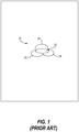
light pattern 20 of a conventional, multi-light source device illustrated inFIG. 1 includescolor shadows light pattern 20 fuzzy and multicolored. - In accordance with one example, a light projection device includes a mixing tube having an open exit end, and a plurality of light sources, each of the plurality of light sources positioned to emit a light stream toward the open exit end of the mixing tube. A diffuser is disposed between the plurality of light sources and the open exit end of the mixing tube, the diffuser configured to diffuse at least one light stream from the plurality of light sources into a diffused light stream. A template is positioned proximate the open exit end of the mixing tube and configured to shape the diffused light stream from the diffuser into a patterned light stream.
- In accordance with another example, a gobo light projection device includes a mixing tube having an open exit end, and a plurality of light sources, each of the plurality of light sources positioned to emit a light stream toward the open exit end of the mixing tube. A prism is disposed between the plurality of light sources and the open exit end of the mixing tube, the prism including an entrance surface, facing the plurality of light sources, configured to diffuse at least one light stream from the plurality of light sources into a diffused light stream, and an exit surface, facing the open exit end of the mixing tube. A template is positioned proximate the open exit end of the mixing tube and configured to shape the diffused light stream from the diffuser into a patterned light stream.
- In accordance with yet another example, a method for mixing light in a light projection device includes directing at least one light stream from a plurality of light stream sources toward an open exit end of a mixing tube, diffusing the at least one light stream to form a diffused light stream, and shaping the diffused light stream to form a patterned light stream.
-
-
FIG. 1 is a diagrammatic depiction of a projected light pattern from a prior art light projection system showing displaced shadows and color fringes. -
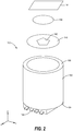
FIG. 2 is a perspective view of a light projection device, according to the present disclosure. -
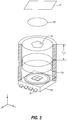
FIG. 3 is a perspective view, in partial cross-section, of the light projection device ofFIG. 2 . -
FIG. 4 is a schematic side elevation view, in cross-section, of the light projection device of -
FIG. 2 . -
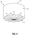
FIG. 5 is a perspective view of one embodiment of a diffuser for use in the light projection device ofFIG. 4 . -
FIG. 6 is a diagrammatic depiction of a projected light pattern from the light projection devices according to the present disclosure. -
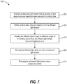
FIG. 7 is a schematic block diagram of a method of mixing light in a light projection device to create a patterned light stream having a homogenous color. - It should be understood that the drawings are not necessarily drawn to scale and that the disclosed embodiments are sometimes illustrated schematically. It is to be further appreciated that the following detailed description is merely exemplary in nature and is not intended to limit the invention or the application and uses thereof. Hence, although the present disclosure is, for convenience of explanation, depicted and described as certain illustrative embodiments, it will be appreciated that it can be implemented in various other types of embodiments and in various other systems and environments.
- The following detailed description is of the best currently contemplated modes of carrying out the invention. The description is not to be taken in a limiting sense, but is made merely for the purpose of illustrating the general principles of the invention, since the scope of the invention is best defined by the appended claims.
- Light projection devices and methods are described herein that produce a projected image having sharp pattern having a homogenous color from multiple light streams. The devices and methods diffuse and mix the light streams within a mixing tube. A template provided at an outlet end of the mixing tube selectively blocks the mixed light streams to create the desired pattern, which may then be focused on a projection surface.
-
FIG. 2 illustrates alight projection device 100 according to the present disclosure. Thelight projection device 100 includes amixing tube 102 having abase end 104 and anexit end 106. Abase 108 encloses thebase end 104 of themixing tube 102, while theexit end 106 is open. A plurality oflight sources 110 are disposed near thebase end 104 of themixing tube 102, with eachlight source 110 positioned to emit alight stream 112 toward theopen exit end 106 of themixing tube 102. As best shown with reference toFIGS. 3 and4 , the plurality oflight sources 110 is coupled to thebase 108. In exemplary embodiments, each of the plurality oflight sources 110 may be provided as an independent light-emitting diode (LED). In other embodiments, the plurality oflight sources 110 includes an integrated LED module having four LED lights. - As best shown in
FIG. 4 , adiffuser 120 is disposed between the plurality oflight sources 110 and theopen exit end 106 of themixing tube 102, thereby to diffuse thelight streams 112 from the plurality oflight sources 110 into a diffusedlight stream 122. More specifically, thediffuser 120 is configured to deflect and/or refract thelight streams 112. In the embodiment illustrated inFIG. 4 , thediffuser 120 includes anentrance surface 130, anexit surface 131, and abody portion 132 extending between theentrance surface 130 and theexit surface 131. In an exemplary embodiment, thediffuser 120 is provided as aprism 128, as best shown inFIG. 5 . Theentrance surface 130 of theprism 128, is non-smooth to diffuse thelight streams 112. In the illustrated embodiment, theentrance surface 130 includes a plurality oftriangular facets 134, withridges 136 andrecesses 138 formed betweenadjacent facets 134. The pattern ofridges 136 shown inFIG. 6 is identified herein as a "rosette" pattern. The highest output area of eachlight source 110 is generally normal to thebase 108, referred to herein as the on-axis direction. Thefacets 134 redirect the light from the on-axis direction to multiple off-axis directions, so that the highest light is now off-angle. That is, eachfacet 134 of theprism 128 displays a virtual image of an adjacent (or off-axis)light source 110, so that the multiple,facets 134 create multiple virtual light sources. An increased number of virtual light sources makes the resultingdiffused light stream 122 appear more homogenous. - A
template 140 is positioned proximate theopen exit end 106 of themixing tube 102 to selectively block thediffused light stream 122 from thediffuser 120 into a patternedlight stream 129. More specifically, thetemplate 140 may be provided as a generally opaque barrier having one ormore openings 142 formed therein, with theopenings 142 corresponding to the desired shape of the patternedlight stream 129. In some embodiments, thetemplate 140 may be provided as a device commonly referred to as a "gobo." - The
mixing tube 102 may have an effective length LEFF, which is described herein as the length of a portion of themixing tube 102 extending between thediffuser 120 and thetemplate 140, that is sufficient to mix thediffused light stream 122 into a homogenous color. That is, when thelight sources 110 generatelight streams 112 having different colors, thediffused light stream 122 has a single, homogenous color. Accordingly, thepatterned light stream 129 may be provided in a wide spectrum of colors by varying the intensity of each differentlycolored light stream 112. Themixing tube 102 may have an internal surface that is highly reflective to project light more efficiently. - As best shown in
FIG. 6 , the resultingpatterned light stream 129 produces animage 150 on aprojection surface 151 havingsharp edges 152 and a homogenous color. In some embodiments, an imaging optic 154 may be positioned downstream of thetemplate 140. The imaging optic 154 may be configured to focus thepatterned light stream 129 onto theprojection surface 151. Accordingly, the imaging optic 154 may be provided as one or more convex lenses, a multi-element optical system (such as a camera or projector lens), or other optical device. - In view of the foregoing, a
method 200 for mixing light in alight projection device 100 to create a patternedlight stream 129 having a homogenous color may be performed, as schematically illustrated by the flow diagram of FIG. 8. The steps of the method may be performed in other sequences than the particular sequence shown, and the particular sequence shown by the flowchart is representative. - The
method 200 begins atblock 202, wherein at least onelight stream 112 from a plurality of light stream sources is directed toward anopen exit end 106 of a mixingtube 102. As noted above, the plurality oflight sources 110 may include different colored LEDs provided either independently or integrally in a module. - At
block 204, at least one of the light streams 112 is diffused to form a diffusedlight stream 122. Diffusing the at least onelight stream 112 may include passing thelight stream 112 through adiffuser 120 configured to diffuse the at least onelight stream 112 into the diffusedlight stream 122. Thediffuser 120 may be provided asprism 128. - At
block 208, the diffusedlight stream 122 is shaped to form a patternedlight stream 129. Shaping the diffusedlight stream 122 into the patternedlight stream 129 may include passing the diffusedlight stream 122 through atemplate 140 havingopenings 142 corresponding to the desired shape of the patternedlight stream 129. - In some embodiments, the
method 200 may further includeblock 210, in which the diffused light is passed through an effective length LEFF of the mixingtube 102 so that the diffusedlight stream 122 has a homogenous color. - In yet other embodiments, the
method 200 may also includeblock 212, in which the patternedlight stream 129 is focused onto aprojection surface 151, such as by passing the patternedlight stream 129 through animaging optic 154. - In view of the foregoing, the light projection devices and methods described herein use multiple light streams to produce a projected image having a sharp pattern and a homogenous color. The devices and methods diffuse and mix the light streams within a mixing tube. A template provided at an outlet end of the mixing tube selectively blocks the diffused light stream to form a desired pattern of light on a projection surface.
- Further, the disclosure includes embodiments according to the following clauses:
- Clause 1. A light projection device (100) comprising:
- a mixing tube (102) having an open exit end (106);
- a plurality of light sources (110), each of the plurality of light sources (110) positioned to emit a light stream (112) toward the open exit end (106) of the mixing tube (102);
- a diffuser (120) disposed between the plurality of light sources (110) and the open exit end (106) of the mixing tube (102), the diffuser (120) configured to diffuse at least one light stream (112) from the plurality of light sources (110) into a diffused light stream (122); and
- a template (140) positioned proximate the open exit end (106) of the mixing tube (102) and configured to shape the diffused light stream (122) from the diffuser (120) into a patterned light stream (129).
- Clause 2. The light projection device (100) of clause 1, in which the diffuser (120) comprises a prism (128).
- Clause 3. The light projection device (100) of clause 2, in which the prism (128) comprises an entrance surface (130) facing the plurality of light sources (110), the entrance surface (130) being non-smooth.
- Clause 4. The light projection device (100) of clause 3, in which the entrance surface (130) comprises ridges (136) formed in a rosette pattern.
- Clause 5. The light projection device (100) of clause 1, in which each of the plurality of light sources (110) comprises a light-emitting diode (LED).
- Clause 6. The light projection device (100) of clause 1, in which the plurality of light sources (110) includes an LED module having four LED lights.
- Clause 7. The light projection device (100) of clause 1, in which the template (140) comprises a gobo.
- Clause 8. The light projection device (100) of clause 1, further comprising an imaging optic (154) positioned downstream of the template (140) and configured to focus the patterned light stream (129).
- Clause 9. The light projection device (100) of clause 8, in which the imaging optic (154) comprises a lens.
- Clause 10. A gobo light projection device (100) comprising:
- a mixing tube (102) having an open exit end (106);
- a plurality of light sources (110), each of the plurality of light sources (110) positioned to emit a light stream (112) toward the open exit end (106) of the mixing tube (102);
- a prism (128) disposed between the plurality of light sources (110) and the open exit end (106) of the mixing tube (102), the prism (128) including:
- an entrance surface (130) facing the plurality of light sources (110) and configured to diffuse at least one light stream (112) from the plurality of light sources (110) into a diffused light stream (122); and
- an exit surface (131), facing the open exit end (106) of the mixing tube (102); and
- a template (140) positioned proximate the open exit end (106) of the mixing tube (102) and configured to shape the diffused light stream (122) from the diffuser (120) into a patterned light stream (129).
- Clause 11. The gobo light projection device (100) of clause 10, in which entrance surface (130) of the prism (128) is non-smooth to diffuse the at least one light stream (112) from the plurality of light sources (110).
- Clause 12. The gobo light projection device (100) of clause 10, in which the entrance surface (130) of the prism (128) comprises ridges (136).
- Clause 13. The gobo light projection device (100) of clause 12, in which the ridges (136) are formed in a rosette pattern.
- Clause 14. The gobo light projection device (100) of clause 10, in which each of the plurality of light sources (110) comprises a light-emitting diode (LED).
- Clause 15. The gobo light projection device (100) of clause 10, in which the plurality of light sources (110) includes an LED module having four LED lights.
- Clause 16. A method (200) for mixing light in a light projection device (100), the method (200) comprising:
- directing at least one light stream (112) from a plurality of light stream (112) sources toward an open exit end (106) of a mixing tube (102);
- diffusing the at least one light stream (112) to form a diffused light stream (122); and
- shaping the diffused light stream (122) to form a patterned light stream (129).
- Clause 17. The method (200) of clause 16, in which diffusing the at least one light stream (112) comprises passing the light stream (112) through a diffuser (120).
- Clause 18. The method (200) of clause 17, in which the diffuser (120) comprises a prism (128) including an entrance surface (130), facing the plurality of light sources (110), and an exit surface (131), facing the open exit end (106) of the mixing tube (102).
- Clause 19. The method (200) of clause 16, further comprising focusing the patterned light stream (129) onto a projection surface (151).
-
Clause 20. The method (200) of clause 16, in which the plurality of light sources (110) includes an LED module having four LED lights.
Claims (15)
- A light projection device (100) comprising:a mixing tube (102) having an open exit end (106);a plurality of light sources (110), each of the plurality of light sources (110) positioned to emit a light stream (112) toward the open exit end (106) of the mixing tube (102);a diffuser (120) disposed between the plurality of light sources (110) and the open exit end (106) of the mixing tube (102), the diffuser (120) configured to diffuse at least one light stream (112) from the plurality of light sources (110) into a diffused light stream (122); anda template (140) positioned proximate the open exit end (106) of the mixing tube (102) and configured to shape the diffused light stream (122) from the diffuser (120) into a patterned light stream (129).
- The light projection device (100) of claim 1, in which the diffuser (120) comprises a prism (128).
- The light projection device (100) of claim 2, in which the prism (128) comprises an entrance surface (130) facing the plurality of light sources (110), the entrance surface (130) being non-smooth.
- The light projection device (100) of claim 3, in which the entrance surface (130) comprises ridges (136) formed in a rosette pattern.
- The light projection device (100) of any one of claims 1-4, in which each of the plurality of light sources (110) comprises a light-emitting diode (LED).
- The light projection device (100) of any one of claims 1-5, in which the plurality of light sources (110) includes an LED module having four LED lights.
- The light projection device (100) of any one of claims 1-6, in which the template (140) comprises a gobo.
- The light projection device (100) of any one of claims 1-7, further comprising an imaging optic (154) positioned downstream of the template (140) and configured to focus the patterned light stream (129).
- The light projection device (100) of claim 8, in which the imaging optic (154) comprises a lens.
- A gobo light projection device (100) comprising:a mixing tube (102) having an open exit end (106);a plurality of light sources (110), each of the plurality of light sources (110) positioned to emit a light stream (112) toward the open exit end (106) of the mixing tube (102);a prism (128) disposed between the plurality of light sources (110) and the open exit end (106) of the mixing tube (102), the prism (128) including:an entrance surface (130) facing the plurality of light sources (110) and configured to diffuse at least one light stream (112) from the plurality of light sources (110) into a diffused light stream (122); andan exit surface (131), facing the open exit end (106) of the mixing tube (102); anda template (140) positioned proximate the open exit end (106) of the mixing tube (102) and configured to shape the diffused light stream (122) from the diffuser (120) into a patterned light stream (129).
- The gobo light projection device (100) of claim 10, in which entrance surface (130) of the prism (128) is non-smooth to diffuse the at least one light stream (112) from the plurality of light sources (110).
- The gobo light projection device (100) of claim 10 or 11, in which the entrance surface (130) of the prism (128) comprises ridges (136).
- The gobo light projection device (100) of claim 12, in which the ridges (136) are formed in a rosette pattern.
- The gobo light projection device (100) of any one of claims 10-13, in which each of the plurality of light sources (110) comprises a light-emitting diode (LED).
- The gobo light projection device (100) of any one of claims 10-14, in which the plurality of light sources (110) includes an LED module having four LED lights.
Applications Claiming Priority (1)
| Application Number | Priority Date | Filing Date | Title |
|---|---|---|---|
| US15/783,215 US10495270B2 (en) | 2017-10-13 | 2017-10-13 | Light protection device for mixing multiple light sources |
Publications (2)
| Publication Number | Publication Date |
|---|---|
| EP3473922A1 true EP3473922A1 (en) | 2019-04-24 |
| EP3473922B1 EP3473922B1 (en) | 2023-11-01 |
Family
ID=63642550
Family Applications (1)
| Application Number | Title | Priority Date | Filing Date |
|---|---|---|---|
| EP18194690.6A Active EP3473922B1 (en) | 2017-10-13 | 2018-09-16 | Light projection device for mixing multiple light sources |
Country Status (2)
| Country | Link |
|---|---|
| US (1) | US10495270B2 (en) |
| EP (1) | EP3473922B1 (en) |
Families Citing this family (3)
| Publication number | Priority date | Publication date | Assignee | Title |
|---|---|---|---|---|
| US11692684B2 (en) * | 2021-02-18 | 2023-07-04 | Designspark, Llc | Filtering assembly for enhancing lighting from a luminaire |
| DE102022117917A1 (en) * | 2022-07-18 | 2024-01-18 | Ams OSRAM Automotive Lighting Systems GmbH | PROJECTOR ARRANGEMENT AND PROJECTION SYSTEM |
| US20260078888A1 (en) * | 2025-11-21 | 2026-03-19 | Robe Lighting S.R.O. | Light Collection System for an LED Array |
Citations (1)
| Publication number | Priority date | Publication date | Assignee | Title |
|---|---|---|---|---|
| EP2177816A2 (en) * | 2008-10-20 | 2010-04-21 | ROBE lighting s.r.o. | A ligth collection system for an led luminaire |
Family Cites Families (10)
| Publication number | Priority date | Publication date | Assignee | Title |
|---|---|---|---|---|
| EP2299307A3 (en) * | 2000-11-03 | 2011-05-04 | Cytyc Corporation | Cytological imaging method |
| US7207682B2 (en) * | 2003-07-15 | 2007-04-24 | Peter Stephens | Kaleidoscope devices |
| JP5532535B2 (en) * | 2006-08-28 | 2014-06-25 | セイコーエプソン株式会社 | projector |
| DE202009011500U1 (en) * | 2009-08-20 | 2010-12-30 | Arnold & Richter Cine Technik Gmbh & Co. Betriebs Kg | Optical system for an LED light |
| US20110235337A1 (en) * | 2010-03-24 | 2011-09-29 | Jacksen International, Ltd | Fade Out Optical Light Masking Projector System |
| WO2012167799A1 (en) | 2011-06-10 | 2012-12-13 | Martin Professional A/S | Multi-mode illumination device |
| US9091416B1 (en) * | 2011-10-11 | 2015-07-28 | Deepsea Power & Light, Inc. | Pathway illumination devices, methods, and systems |
| US10302275B2 (en) * | 2013-06-19 | 2019-05-28 | Bright View Technologies Corporation | Microstructure-based diffusers for creating batwing lighting patterns |
| EP2995852B1 (en) * | 2014-09-04 | 2019-03-13 | Harman Professional Denmark ApS | Projecting light fixture with dymamic illumination of beam shaping object |
| US10480732B2 (en) * | 2015-10-06 | 2019-11-19 | AVID Labs, LLC | Gobo and method for manufacturing a gobo |
-
2017
- 2017-10-13 US US15/783,215 patent/US10495270B2/en active Active
-
2018
- 2018-09-16 EP EP18194690.6A patent/EP3473922B1/en active Active
Patent Citations (1)
| Publication number | Priority date | Publication date | Assignee | Title |
|---|---|---|---|---|
| EP2177816A2 (en) * | 2008-10-20 | 2010-04-21 | ROBE lighting s.r.o. | A ligth collection system for an led luminaire |
Also Published As
| Publication number | Publication date |
|---|---|
| US20190113184A1 (en) | 2019-04-18 |
| EP3473922B1 (en) | 2023-11-01 |
| US10495270B2 (en) | 2019-12-03 |
Similar Documents
| Publication | Publication Date | Title |
|---|---|---|
| CN109312913B (en) | Special flower effect beam and wash light fixtures | |
| EP2177816B1 (en) | A ligth collection system for an led luminaire | |
| US9903553B2 (en) | Light-guiding pillar and vehicle lamp using the same | |
| EP3052858B1 (en) | Illumination device with spinning zoom lens | |
| US8770762B2 (en) | Projecting device with multiple mutual boosting light sources | |
| CN102348929B (en) | Pattern-projecting light-output system | |
| EP3473922A1 (en) | Light projection device for mixing multiple light sources | |
| CN116202049B (en) | Vehicle lights | |
| KR20080085722A (en) | LED spotlight | |
| WO2015138483A2 (en) | Optical system for an led luminaire | |
| KR20100133888A (en) | Light irradiation device | |
| US20170205034A1 (en) | Illuminating apparatus | |
| US20190195446A9 (en) | Optical system for a led luminaire | |
| TWI630345B (en) | Illumination apparatus | |
| CN109312902B (en) | Dyeing light illuminating device with special effect function | |
| JP2004151720A (en) | Input coupling device | |
| CN113531475B (en) | Lamp assembly, vehicle lamp and vehicle | |
| TWI711788B (en) | Operating lamp apparatus | |
| CN111947065A (en) | Surgical Light Equipment | |
| DE102025102661B3 (en) | Projection device for a motor vehicle and method for projecting optically perceptible elements | |
| TWM538214U (en) | Traffic indication billboard | |
| CN207122801U (en) | A kind of stage lamp lighting apparatus | |
| CN114198711A (en) | Method and system for realizing two light entry functions for single-wall thick parts | |
| CN111412437A (en) | Lighting device | |
| TW202026563A (en) | Illumination apparatus |
Legal Events
| Date | Code | Title | Description |
|---|---|---|---|
| PUAI | Public reference made under article 153(3) epc to a published international application that has entered the european phase |
Free format text: ORIGINAL CODE: 0009012 |
|
| STAA | Information on the status of an ep patent application or granted ep patent |
Free format text: STATUS: REQUEST FOR EXAMINATION WAS MADE |
|
| 17P | Request for examination filed |
Effective date: 20180917 |
|
| AK | Designated contracting states |
Kind code of ref document: A1 Designated state(s): AL AT BE BG CH CY CZ DE DK EE ES FI FR GB GR HR HU IE IS IT LI LT LU LV MC MK MT NL NO PL PT RO RS SE SI SK SM TR |
|
| AX | Request for extension of the european patent |
Extension state: BA ME |
|
| RBV | Designated contracting states (corrected) |
Designated state(s): AL AT BE BG CH CY CZ DE DK EE ES FI FR GB GR HR HU IE IS IT LI LT LU LV MC MK MT NL NO PL PT RO RS SE SI SK SM TR |
|
| STAA | Information on the status of an ep patent application or granted ep patent |
Free format text: STATUS: EXAMINATION IS IN PROGRESS |
|
| 17Q | First examination report despatched |
Effective date: 20200805 |
|
| REG | Reference to a national code |
Ref country code: DE Ref legal event code: R079 Free format text: PREVIOUS MAIN CLASS: F21V0008000000 Ipc: F21S0010000000 Ref country code: DE Ref legal event code: R079 Ref document number: 602018060289 Country of ref document: DE Free format text: PREVIOUS MAIN CLASS: F21V0008000000 Ipc: F21S0010000000 |
|
| GRAP | Despatch of communication of intention to grant a patent |
Free format text: ORIGINAL CODE: EPIDOSNIGR1 |
|
| STAA | Information on the status of an ep patent application or granted ep patent |
Free format text: STATUS: GRANT OF PATENT IS INTENDED |
|
| RAP3 | Party data changed (applicant data changed or rights of an application transferred) |
Owner name: THE BOEING COMPANY |
|
| RIC1 | Information provided on ipc code assigned before grant |
Ipc: G02B 5/02 20060101ALI20230217BHEP Ipc: G02B 27/18 20060101ALI20230217BHEP Ipc: G02B 27/10 20060101ALI20230217BHEP Ipc: G02B 19/00 20060101ALI20230217BHEP Ipc: F21S 10/00 20060101AFI20230217BHEP |
|
| INTG | Intention to grant announced |
Effective date: 20230316 |
|
| GRAJ | Information related to disapproval of communication of intention to grant by the applicant or resumption of examination proceedings by the epo deleted |
Free format text: ORIGINAL CODE: EPIDOSDIGR1 |
|
| STAA | Information on the status of an ep patent application or granted ep patent |
Free format text: STATUS: EXAMINATION IS IN PROGRESS |
|
| GRAP | Despatch of communication of intention to grant a patent |
Free format text: ORIGINAL CODE: EPIDOSNIGR1 |
|
| STAA | Information on the status of an ep patent application or granted ep patent |
Free format text: STATUS: GRANT OF PATENT IS INTENDED |
|
| INTC | Intention to grant announced (deleted) | ||
| INTG | Intention to grant announced |
Effective date: 20230509 |
|
| P01 | Opt-out of the competence of the unified patent court (upc) registered |
Effective date: 20230705 |
|
| GRAS | Grant fee paid |
Free format text: ORIGINAL CODE: EPIDOSNIGR3 |
|
| GRAA | (expected) grant |
Free format text: ORIGINAL CODE: 0009210 |
|
| STAA | Information on the status of an ep patent application or granted ep patent |
Free format text: STATUS: THE PATENT HAS BEEN GRANTED |
|
| AK | Designated contracting states |
Kind code of ref document: B1 Designated state(s): AL AT BE BG CH CY CZ DE DK EE ES FI FR GB GR HR HU IE IS IT LI LT LU LV MC MK MT NL NO PL PT RO RS SE SI SK SM TR |
|
| REG | Reference to a national code |
Ref country code: GB Ref legal event code: FG4D |
|
| REG | Reference to a national code |
Ref country code: CH Ref legal event code: EP |
|
| REG | Reference to a national code |
Ref country code: DE Ref legal event code: R096 Ref document number: 602018060289 Country of ref document: DE |
|
| REG | Reference to a national code |
Ref country code: IE Ref legal event code: FG4D |
|
| REG | Reference to a national code |
Ref country code: LT Ref legal event code: MG9D |
|
| REG | Reference to a national code |
Ref country code: NL Ref legal event code: MP Effective date: 20231101 |
|
| PG25 | Lapsed in a contracting state [announced via postgrant information from national office to epo] |
Ref country code: GR Free format text: LAPSE BECAUSE OF FAILURE TO SUBMIT A TRANSLATION OF THE DESCRIPTION OR TO PAY THE FEE WITHIN THE PRESCRIBED TIME-LIMIT Effective date: 20240202 |
|
| PG25 | Lapsed in a contracting state [announced via postgrant information from national office to epo] |
Ref country code: IS Free format text: LAPSE BECAUSE OF FAILURE TO SUBMIT A TRANSLATION OF THE DESCRIPTION OR TO PAY THE FEE WITHIN THE PRESCRIBED TIME-LIMIT Effective date: 20240301 |
|
| PG25 | Lapsed in a contracting state [announced via postgrant information from national office to epo] |
Ref country code: LT Free format text: LAPSE BECAUSE OF FAILURE TO SUBMIT A TRANSLATION OF THE DESCRIPTION OR TO PAY THE FEE WITHIN THE PRESCRIBED TIME-LIMIT Effective date: 20231101 |
|
| REG | Reference to a national code |
Ref country code: AT Ref legal event code: MK05 Ref document number: 1627582 Country of ref document: AT Kind code of ref document: T Effective date: 20231101 |
|
| PG25 | Lapsed in a contracting state [announced via postgrant information from national office to epo] |
Ref country code: NL Free format text: LAPSE BECAUSE OF FAILURE TO SUBMIT A TRANSLATION OF THE DESCRIPTION OR TO PAY THE FEE WITHIN THE PRESCRIBED TIME-LIMIT Effective date: 20231101 |
|
| PG25 | Lapsed in a contracting state [announced via postgrant information from national office to epo] |
Ref country code: AT Free format text: LAPSE BECAUSE OF FAILURE TO SUBMIT A TRANSLATION OF THE DESCRIPTION OR TO PAY THE FEE WITHIN THE PRESCRIBED TIME-LIMIT Effective date: 20231101 |
|
| PG25 | Lapsed in a contracting state [announced via postgrant information from national office to epo] |
Ref country code: ES Free format text: LAPSE BECAUSE OF FAILURE TO SUBMIT A TRANSLATION OF THE DESCRIPTION OR TO PAY THE FEE WITHIN THE PRESCRIBED TIME-LIMIT Effective date: 20231101 |
|
| PG25 | Lapsed in a contracting state [announced via postgrant information from national office to epo] |
Ref country code: NL Free format text: LAPSE BECAUSE OF FAILURE TO SUBMIT A TRANSLATION OF THE DESCRIPTION OR TO PAY THE FEE WITHIN THE PRESCRIBED TIME-LIMIT Effective date: 20231101 Ref country code: LT Free format text: LAPSE BECAUSE OF FAILURE TO SUBMIT A TRANSLATION OF THE DESCRIPTION OR TO PAY THE FEE WITHIN THE PRESCRIBED TIME-LIMIT Effective date: 20231101 Ref country code: IS Free format text: LAPSE BECAUSE OF FAILURE TO SUBMIT A TRANSLATION OF THE DESCRIPTION OR TO PAY THE FEE WITHIN THE PRESCRIBED TIME-LIMIT Effective date: 20240301 Ref country code: GR Free format text: LAPSE BECAUSE OF FAILURE TO SUBMIT A TRANSLATION OF THE DESCRIPTION OR TO PAY THE FEE WITHIN THE PRESCRIBED TIME-LIMIT Effective date: 20240202 Ref country code: ES Free format text: LAPSE BECAUSE OF FAILURE TO SUBMIT A TRANSLATION OF THE DESCRIPTION OR TO PAY THE FEE WITHIN THE PRESCRIBED TIME-LIMIT Effective date: 20231101 Ref country code: BG Free format text: LAPSE BECAUSE OF FAILURE TO SUBMIT A TRANSLATION OF THE DESCRIPTION OR TO PAY THE FEE WITHIN THE PRESCRIBED TIME-LIMIT Effective date: 20240201 Ref country code: AT Free format text: LAPSE BECAUSE OF FAILURE TO SUBMIT A TRANSLATION OF THE DESCRIPTION OR TO PAY THE FEE WITHIN THE PRESCRIBED TIME-LIMIT Effective date: 20231101 Ref country code: PT Free format text: LAPSE BECAUSE OF FAILURE TO SUBMIT A TRANSLATION OF THE DESCRIPTION OR TO PAY THE FEE WITHIN THE PRESCRIBED TIME-LIMIT Effective date: 20240301 |
|
| PG25 | Lapsed in a contracting state [announced via postgrant information from national office to epo] |
Ref country code: SE Free format text: LAPSE BECAUSE OF FAILURE TO SUBMIT A TRANSLATION OF THE DESCRIPTION OR TO PAY THE FEE WITHIN THE PRESCRIBED TIME-LIMIT Effective date: 20231101 Ref country code: RS Free format text: LAPSE BECAUSE OF FAILURE TO SUBMIT A TRANSLATION OF THE DESCRIPTION OR TO PAY THE FEE WITHIN THE PRESCRIBED TIME-LIMIT Effective date: 20231101 Ref country code: PL Free format text: LAPSE BECAUSE OF FAILURE TO SUBMIT A TRANSLATION OF THE DESCRIPTION OR TO PAY THE FEE WITHIN THE PRESCRIBED TIME-LIMIT Effective date: 20231101 Ref country code: NO Free format text: LAPSE BECAUSE OF FAILURE TO SUBMIT A TRANSLATION OF THE DESCRIPTION OR TO PAY THE FEE WITHIN THE PRESCRIBED TIME-LIMIT Effective date: 20240201 Ref country code: LV Free format text: LAPSE BECAUSE OF FAILURE TO SUBMIT A TRANSLATION OF THE DESCRIPTION OR TO PAY THE FEE WITHIN THE PRESCRIBED TIME-LIMIT Effective date: 20231101 Ref country code: HR Free format text: LAPSE BECAUSE OF FAILURE TO SUBMIT A TRANSLATION OF THE DESCRIPTION OR TO PAY THE FEE WITHIN THE PRESCRIBED TIME-LIMIT Effective date: 20231101 |
|
| PG25 | Lapsed in a contracting state [announced via postgrant information from national office to epo] |
Ref country code: DK Free format text: LAPSE BECAUSE OF FAILURE TO SUBMIT A TRANSLATION OF THE DESCRIPTION OR TO PAY THE FEE WITHIN THE PRESCRIBED TIME-LIMIT Effective date: 20231101 |
|
| PG25 | Lapsed in a contracting state [announced via postgrant information from national office to epo] |
Ref country code: CZ Free format text: LAPSE BECAUSE OF FAILURE TO SUBMIT A TRANSLATION OF THE DESCRIPTION OR TO PAY THE FEE WITHIN THE PRESCRIBED TIME-LIMIT Effective date: 20231101 |
|
| PG25 | Lapsed in a contracting state [announced via postgrant information from national office to epo] |
Ref country code: SK Free format text: LAPSE BECAUSE OF FAILURE TO SUBMIT A TRANSLATION OF THE DESCRIPTION OR TO PAY THE FEE WITHIN THE PRESCRIBED TIME-LIMIT Effective date: 20231101 |
|
| PG25 | Lapsed in a contracting state [announced via postgrant information from national office to epo] |
Ref country code: SM Free format text: LAPSE BECAUSE OF FAILURE TO SUBMIT A TRANSLATION OF THE DESCRIPTION OR TO PAY THE FEE WITHIN THE PRESCRIBED TIME-LIMIT Effective date: 20231101 Ref country code: SK Free format text: LAPSE BECAUSE OF FAILURE TO SUBMIT A TRANSLATION OF THE DESCRIPTION OR TO PAY THE FEE WITHIN THE PRESCRIBED TIME-LIMIT Effective date: 20231101 Ref country code: IT Free format text: LAPSE BECAUSE OF FAILURE TO SUBMIT A TRANSLATION OF THE DESCRIPTION OR TO PAY THE FEE WITHIN THE PRESCRIBED TIME-LIMIT Effective date: 20231101 Ref country code: EE Free format text: LAPSE BECAUSE OF FAILURE TO SUBMIT A TRANSLATION OF THE DESCRIPTION OR TO PAY THE FEE WITHIN THE PRESCRIBED TIME-LIMIT Effective date: 20231101 Ref country code: DK Free format text: LAPSE BECAUSE OF FAILURE TO SUBMIT A TRANSLATION OF THE DESCRIPTION OR TO PAY THE FEE WITHIN THE PRESCRIBED TIME-LIMIT Effective date: 20231101 Ref country code: CZ Free format text: LAPSE BECAUSE OF FAILURE TO SUBMIT A TRANSLATION OF THE DESCRIPTION OR TO PAY THE FEE WITHIN THE PRESCRIBED TIME-LIMIT Effective date: 20231101 |
|
| REG | Reference to a national code |
Ref country code: DE Ref legal event code: R097 Ref document number: 602018060289 Country of ref document: DE |
|
| PLBE | No opposition filed within time limit |
Free format text: ORIGINAL CODE: 0009261 |
|
| STAA | Information on the status of an ep patent application or granted ep patent |
Free format text: STATUS: NO OPPOSITION FILED WITHIN TIME LIMIT |
|
| 26N | No opposition filed |
Effective date: 20240802 |
|
| PG25 | Lapsed in a contracting state [announced via postgrant information from national office to epo] |
Ref country code: SI Free format text: LAPSE BECAUSE OF FAILURE TO SUBMIT A TRANSLATION OF THE DESCRIPTION OR TO PAY THE FEE WITHIN THE PRESCRIBED TIME-LIMIT Effective date: 20231101 |
|
| PG25 | Lapsed in a contracting state [announced via postgrant information from national office to epo] |
Ref country code: SI Free format text: LAPSE BECAUSE OF FAILURE TO SUBMIT A TRANSLATION OF THE DESCRIPTION OR TO PAY THE FEE WITHIN THE PRESCRIBED TIME-LIMIT Effective date: 20231101 |
|
| PG25 | Lapsed in a contracting state [announced via postgrant information from national office to epo] |
Ref country code: MC Free format text: LAPSE BECAUSE OF FAILURE TO SUBMIT A TRANSLATION OF THE DESCRIPTION OR TO PAY THE FEE WITHIN THE PRESCRIBED TIME-LIMIT Effective date: 20231101 |
|
| REG | Reference to a national code |
Ref country code: CH Ref legal event code: PL |
|
| PG25 | Lapsed in a contracting state [announced via postgrant information from national office to epo] |
Ref country code: LU Free format text: LAPSE BECAUSE OF NON-PAYMENT OF DUE FEES Effective date: 20240916 |
|
| REG | Reference to a national code |
Ref country code: BE Ref legal event code: MM Effective date: 20240930 |
|
| PG25 | Lapsed in a contracting state [announced via postgrant information from national office to epo] |
Ref country code: BE Free format text: LAPSE BECAUSE OF NON-PAYMENT OF DUE FEES Effective date: 20240930 |
|
| PG25 | Lapsed in a contracting state [announced via postgrant information from national office to epo] |
Ref country code: CH Free format text: LAPSE BECAUSE OF NON-PAYMENT OF DUE FEES Effective date: 20240930 |
|
| PG25 | Lapsed in a contracting state [announced via postgrant information from national office to epo] |
Ref country code: IE Free format text: LAPSE BECAUSE OF NON-PAYMENT OF DUE FEES Effective date: 20240916 |
|
| PG25 | Lapsed in a contracting state [announced via postgrant information from national office to epo] |
Ref country code: FI Free format text: LAPSE BECAUSE OF FAILURE TO SUBMIT A TRANSLATION OF THE DESCRIPTION OR TO PAY THE FEE WITHIN THE PRESCRIBED TIME-LIMIT Effective date: 20231101 |
|
| PGFP | Annual fee paid to national office [announced via postgrant information from national office to epo] |
Ref country code: DE Payment date: 20250929 Year of fee payment: 8 |
|
| PGFP | Annual fee paid to national office [announced via postgrant information from national office to epo] |
Ref country code: GB Payment date: 20250929 Year of fee payment: 8 |
|
| PGFP | Annual fee paid to national office [announced via postgrant information from national office to epo] |
Ref country code: FR Payment date: 20250925 Year of fee payment: 8 |
|
| PG25 | Lapsed in a contracting state [announced via postgrant information from national office to epo] |
Ref country code: RO Free format text: LAPSE BECAUSE OF FAILURE TO SUBMIT A TRANSLATION OF THE DESCRIPTION OR TO PAY THE FEE WITHIN THE PRESCRIBED TIME-LIMIT Effective date: 20231101 |
|
| PG25 | Lapsed in a contracting state [announced via postgrant information from national office to epo] |
Ref country code: CY Free format text: LAPSE BECAUSE OF FAILURE TO SUBMIT A TRANSLATION OF THE DESCRIPTION OR TO PAY THE FEE WITHIN THE PRESCRIBED TIME-LIMIT; INVALID AB INITIO Effective date: 20180916 |
|
| PG25 | Lapsed in a contracting state [announced via postgrant information from national office to epo] |
Ref country code: HU Free format text: LAPSE BECAUSE OF FAILURE TO SUBMIT A TRANSLATION OF THE DESCRIPTION OR TO PAY THE FEE WITHIN THE PRESCRIBED TIME-LIMIT; INVALID AB INITIO Effective date: 20180916 |