EP3473914B1 - Lubricant scoop - Google Patents
Lubricant scoop Download PDFInfo
- Publication number
- EP3473914B1 EP3473914B1 EP18201047.0A EP18201047A EP3473914B1 EP 3473914 B1 EP3473914 B1 EP 3473914B1 EP 18201047 A EP18201047 A EP 18201047A EP 3473914 B1 EP3473914 B1 EP 3473914B1
- Authority
- EP
- European Patent Office
- Prior art keywords
- lubricant
- annular
- radially
- annular body
- transition surface
- Prior art date
- Legal status (The legal status is an assumption and is not a legal conclusion. Google has not performed a legal analysis and makes no representation as to the accuracy of the status listed.)
- Active
Links
Images



Classifications
-
- F—MECHANICAL ENGINEERING; LIGHTING; HEATING; WEAPONS; BLASTING
- F01—MACHINES OR ENGINES IN GENERAL; ENGINE PLANTS IN GENERAL; STEAM ENGINES
- F01D—NON-POSITIVE DISPLACEMENT MACHINES OR ENGINES, e.g. STEAM TURBINES
- F01D25/00—Component parts, details, or accessories, not provided for in, or of interest apart from, other groups
- F01D25/18—Lubricating arrangements
-
- F—MECHANICAL ENGINEERING; LIGHTING; HEATING; WEAPONS; BLASTING
- F02—COMBUSTION ENGINES; HOT-GAS OR COMBUSTION-PRODUCT ENGINE PLANTS
- F02C—GAS-TURBINE PLANTS; AIR INTAKES FOR JET-PROPULSION PLANTS; CONTROLLING FUEL SUPPLY IN AIR-BREATHING JET-PROPULSION PLANTS
- F02C7/00—Features, components parts, details or accessories, not provided for in, or of interest apart form groups F02C1/00 - F02C6/00; Air intakes for jet-propulsion plants
- F02C7/06—Arrangements of bearings; Lubricating
-
- F—MECHANICAL ENGINEERING; LIGHTING; HEATING; WEAPONS; BLASTING
- F16—ENGINEERING ELEMENTS AND UNITS; GENERAL MEASURES FOR PRODUCING AND MAINTAINING EFFECTIVE FUNCTIONING OF MACHINES OR INSTALLATIONS; THERMAL INSULATION IN GENERAL
- F16C—SHAFTS; FLEXIBLE SHAFTS; ELEMENTS OR CRANKSHAFT MECHANISMS; ROTARY BODIES OTHER THAN GEARING ELEMENTS; BEARINGS
- F16C33/00—Parts of bearings; Special methods for making bearings or parts thereof
- F16C33/30—Parts of ball or roller bearings
- F16C33/66—Special parts or details in view of lubrication
-
- F—MECHANICAL ENGINEERING; LIGHTING; HEATING; WEAPONS; BLASTING
- F16—ENGINEERING ELEMENTS AND UNITS; GENERAL MEASURES FOR PRODUCING AND MAINTAINING EFFECTIVE FUNCTIONING OF MACHINES OR INSTALLATIONS; THERMAL INSULATION IN GENERAL
- F16C—SHAFTS; FLEXIBLE SHAFTS; ELEMENTS OR CRANKSHAFT MECHANISMS; ROTARY BODIES OTHER THAN GEARING ELEMENTS; BEARINGS
- F16C33/00—Parts of bearings; Special methods for making bearings or parts thereof
- F16C33/30—Parts of ball or roller bearings
- F16C33/66—Special parts or details in view of lubrication
- F16C33/6637—Special parts or details in view of lubrication with liquid lubricant
- F16C33/6659—Details of supply of the liquid to the bearing, e.g. passages or nozzles
-
- F—MECHANICAL ENGINEERING; LIGHTING; HEATING; WEAPONS; BLASTING
- F16—ENGINEERING ELEMENTS AND UNITS; GENERAL MEASURES FOR PRODUCING AND MAINTAINING EFFECTIVE FUNCTIONING OF MACHINES OR INSTALLATIONS; THERMAL INSULATION IN GENERAL
- F16H—GEARING
- F16H57/00—General details of gearing
- F16H57/04—Features relating to lubrication or cooling or heating
-
- F—MECHANICAL ENGINEERING; LIGHTING; HEATING; WEAPONS; BLASTING
- F16—ENGINEERING ELEMENTS AND UNITS; GENERAL MEASURES FOR PRODUCING AND MAINTAINING EFFECTIVE FUNCTIONING OF MACHINES OR INSTALLATIONS; THERMAL INSULATION IN GENERAL
- F16H—GEARING
- F16H57/00—General details of gearing
- F16H57/04—Features relating to lubrication or cooling or heating
- F16H57/042—Guidance of lubricant
- F16H57/0421—Guidance of lubricant on or within the casing, e.g. shields or baffles for collecting lubricant, tubes, pipes, grooves, channels or the like
- F16H57/0423—Lubricant guiding means mounted or supported on the casing, e.g. shields or baffles for collecting lubricant, tubes or pipes
-
- F—MECHANICAL ENGINEERING; LIGHTING; HEATING; WEAPONS; BLASTING
- F16—ENGINEERING ELEMENTS AND UNITS; GENERAL MEASURES FOR PRODUCING AND MAINTAINING EFFECTIVE FUNCTIONING OF MACHINES OR INSTALLATIONS; THERMAL INSULATION IN GENERAL
- F16H—GEARING
- F16H57/00—General details of gearing
- F16H57/04—Features relating to lubrication or cooling or heating
- F16H57/0456—Lubrication by injection; Injection nozzles or tubes therefor
-
- F—MECHANICAL ENGINEERING; LIGHTING; HEATING; WEAPONS; BLASTING
- F16—ENGINEERING ELEMENTS AND UNITS; GENERAL MEASURES FOR PRODUCING AND MAINTAINING EFFECTIVE FUNCTIONING OF MACHINES OR INSTALLATIONS; THERMAL INSULATION IN GENERAL
- F16N—LUBRICATING
- F16N7/00—Arrangements for supplying oil or unspecified lubricant from a stationary reservoir or the equivalent in or on the machine or member to be lubricated
- F16N7/14—Arrangements for supplying oil or unspecified lubricant from a stationary reservoir or the equivalent in or on the machine or member to be lubricated the lubricant being conveyed from the reservoir by mechanical means
- F16N7/16—Arrangements for supplying oil or unspecified lubricant from a stationary reservoir or the equivalent in or on the machine or member to be lubricated the lubricant being conveyed from the reservoir by mechanical means the oil being carried up by a lifting device
-
- F—MECHANICAL ENGINEERING; LIGHTING; HEATING; WEAPONS; BLASTING
- F16—ENGINEERING ELEMENTS AND UNITS; GENERAL MEASURES FOR PRODUCING AND MAINTAINING EFFECTIVE FUNCTIONING OF MACHINES OR INSTALLATIONS; THERMAL INSULATION IN GENERAL
- F16N—LUBRICATING
- F16N7/00—Arrangements for supplying oil or unspecified lubricant from a stationary reservoir or the equivalent in or on the machine or member to be lubricated
- F16N7/30—Arrangements for supplying oil or unspecified lubricant from a stationary reservoir or the equivalent in or on the machine or member to be lubricated the oil being fed or carried along by another fluid
- F16N7/32—Mist lubrication
-
- F—MECHANICAL ENGINEERING; LIGHTING; HEATING; WEAPONS; BLASTING
- F05—INDEXING SCHEMES RELATING TO ENGINES OR PUMPS IN VARIOUS SUBCLASSES OF CLASSES F01-F04
- F05D—INDEXING SCHEME FOR ASPECTS RELATING TO NON-POSITIVE-DISPLACEMENT MACHINES OR ENGINES, GAS-TURBINES OR JET-PROPULSION PLANTS
- F05D2220/00—Application
- F05D2220/30—Application in turbines
- F05D2220/32—Application in turbines in gas turbines
-
- F—MECHANICAL ENGINEERING; LIGHTING; HEATING; WEAPONS; BLASTING
- F05—INDEXING SCHEMES RELATING TO ENGINES OR PUMPS IN VARIOUS SUBCLASSES OF CLASSES F01-F04
- F05D—INDEXING SCHEME FOR ASPECTS RELATING TO NON-POSITIVE-DISPLACEMENT MACHINES OR ENGINES, GAS-TURBINES OR JET-PROPULSION PLANTS
- F05D2240/00—Components
- F05D2240/50—Bearings
-
- F—MECHANICAL ENGINEERING; LIGHTING; HEATING; WEAPONS; BLASTING
- F05—INDEXING SCHEMES RELATING TO ENGINES OR PUMPS IN VARIOUS SUBCLASSES OF CLASSES F01-F04
- F05D—INDEXING SCHEME FOR ASPECTS RELATING TO NON-POSITIVE-DISPLACEMENT MACHINES OR ENGINES, GAS-TURBINES OR JET-PROPULSION PLANTS
- F05D2240/00—Components
- F05D2240/60—Shafts
-
- F—MECHANICAL ENGINEERING; LIGHTING; HEATING; WEAPONS; BLASTING
- F05—INDEXING SCHEMES RELATING TO ENGINES OR PUMPS IN VARIOUS SUBCLASSES OF CLASSES F01-F04
- F05D—INDEXING SCHEME FOR ASPECTS RELATING TO NON-POSITIVE-DISPLACEMENT MACHINES OR ENGINES, GAS-TURBINES OR JET-PROPULSION PLANTS
- F05D2240/00—Components
- F05D2240/70—Slinger plates or washers
-
- F—MECHANICAL ENGINEERING; LIGHTING; HEATING; WEAPONS; BLASTING
- F05—INDEXING SCHEMES RELATING TO ENGINES OR PUMPS IN VARIOUS SUBCLASSES OF CLASSES F01-F04
- F05D—INDEXING SCHEME FOR ASPECTS RELATING TO NON-POSITIVE-DISPLACEMENT MACHINES OR ENGINES, GAS-TURBINES OR JET-PROPULSION PLANTS
- F05D2260/00—Function
- F05D2260/98—Lubrication
-
- F—MECHANICAL ENGINEERING; LIGHTING; HEATING; WEAPONS; BLASTING
- F16—ENGINEERING ELEMENTS AND UNITS; GENERAL MEASURES FOR PRODUCING AND MAINTAINING EFFECTIVE FUNCTIONING OF MACHINES OR INSTALLATIONS; THERMAL INSULATION IN GENERAL
- F16C—SHAFTS; FLEXIBLE SHAFTS; ELEMENTS OR CRANKSHAFT MECHANISMS; ROTARY BODIES OTHER THAN GEARING ELEMENTS; BEARINGS
- F16C2326/00—Articles relating to transporting
- F16C2326/43—Aeroplanes; Helicopters
-
- F—MECHANICAL ENGINEERING; LIGHTING; HEATING; WEAPONS; BLASTING
- F16—ENGINEERING ELEMENTS AND UNITS; GENERAL MEASURES FOR PRODUCING AND MAINTAINING EFFECTIVE FUNCTIONING OF MACHINES OR INSTALLATIONS; THERMAL INSULATION IN GENERAL
- F16C—SHAFTS; FLEXIBLE SHAFTS; ELEMENTS OR CRANKSHAFT MECHANISMS; ROTARY BODIES OTHER THAN GEARING ELEMENTS; BEARINGS
- F16C2360/00—Engines or pumps
- F16C2360/23—Gas turbine engines
-
- F—MECHANICAL ENGINEERING; LIGHTING; HEATING; WEAPONS; BLASTING
- F16—ENGINEERING ELEMENTS AND UNITS; GENERAL MEASURES FOR PRODUCING AND MAINTAINING EFFECTIVE FUNCTIONING OF MACHINES OR INSTALLATIONS; THERMAL INSULATION IN GENERAL
- F16N—LUBRICATING
- F16N2210/00—Applications
- F16N2210/02—Turbines
-
- F—MECHANICAL ENGINEERING; LIGHTING; HEATING; WEAPONS; BLASTING
- F16—ENGINEERING ELEMENTS AND UNITS; GENERAL MEASURES FOR PRODUCING AND MAINTAINING EFFECTIVE FUNCTIONING OF MACHINES OR INSTALLATIONS; THERMAL INSULATION IN GENERAL
- F16N—LUBRICATING
- F16N2210/00—Applications
- F16N2210/14—Bearings
Definitions
- the present invention relates to gas turbine engines and, more particularly, to lubrication delivery systems for rotating componentry within gas turbine engines.
- a lubricant scoop is disclosed.
- the lubricant scoop includes an annular body configured for engagement with a shaft rotating about a central axis.
- the annular body includes a first annular portion and a second annular portion.
- the first annular portion has a radially oriented entrance surface and a first axially oriented transition surface.
- the second annular portion is disposed adjacent the first annular portion and include a second axially oriented transition surface, a primary redirection member spaced radially outward from the second axially oriented transition surface, a radially oriented exit surface and an exit conduit having an opening positioned proximate the radially oriented exit surface.
- the first annular portion includes a circumferential lubricant inlet defined by a space between the radially oriented entrance surface and the redirection member.
- the circumferential lubricant inlet may be defined by an annular plane coaxial with and parallel to the central axis.
- the first axially oriented transition surface intersects the second axially oriented transition surface at an intersection region where intersecting portions of both surfaces are coaxial with and parallel to the central axis.
- the radially oriented entrance surface and the first axially oriented transition surface intersect at a first portion having a first turning surface defined by a first radius of curvature.
- the second axially oriented transition surface and the radially oriented exit surface radially oriented exit surface intersect at a second portion having a second turning surface defined by a second radius of curvature.
- a radially outermost portion of the radially oriented entrance surface is defined by a radial plane disposed perpendicular to the central axis.
- the primary redirection member is an annular member that extends axially from the second annular portion toward the first annular portion.
- the primary redirection member has a proximal end connected to the second annular portion radially outward of the opening to the exit conduit.
- the primary redirection member has a distal end that terminates at an axial location coincident with an axially location where the first axially oriented transition surface intersects the second axially oriented transition surface.
- the distal end of the primary redirection member includes a secondary redirection member directed radially inward of the primary redirection member.
- a lubricant scoop in accordance with various embodiments, includes a first annular body configured for engagement with a shaft rotating about a central axis.
- the first annular body may include a radially oriented entrance surface and a first axially oriented transition surface.
- the lubricant scoop may also include a second annular body configured for engagement with the shaft.
- the second annular body may include a second axially oriented transition surface, a primary redirection member spaced radially outward from the second axially oriented transition surface, a radially oriented exit surface and an exit conduit having an opening positioned on the radially oriented exit surface.
- the second annular body is configured for positioning adjacent the first annular body such that the second axially oriented transition surface intersects with the first axially oriented transition surface.
- the primary redirection member is an annular member that extends axially from the second axial body toward the first axial body.
- the primary redirection member may have a proximal end connected to the second annular body radially outward of the opening to the exit conduit.
- the primary redirection member may have a distal end that terminates at an axial location coincident with an axially location where the first axially oriented transition surface intersects the second axially oriented transition surface.
- the distal end of the primary redirection member includes a secondary redirection member directed radially inward of the primary redirection member.
- a gas turbine engine in accordance with the invention, includes a shaft configured to rotate about a central axis and a rotating component configured to rotate with the shaft.
- the gas turbine engine may include a lubricant scoop.
- the lubricant scoop includes an annular body engaged with the shaft.
- the annular body includes a first annular portion having a radially oriented entrance surface and a first axially oriented transition surface.
- the lubricant scoop includes a second annular portion adjacent the first annular portion.
- the second annular portion having a second axially oriented transition surface, a primary redirection member spaced radially outward from the second axially oriented transition surface, a radially oriented exit surface and an exit conduit having an opening positioned on the radially oriented exit surface.
- the exit conduit is be configured to communicate lubricant to the rotating component.
- a lubricant spray nozzle is directed toward a circumferential lubricant inlet defined by a space between the radially oriented entrance surface and the redirection member.
- the first annular portion includes a circumferential lubricant inlet defined by a space between the radially oriented entrance surface and the primary redirection member.
- the primary redirection member is an annular member that extends axially from the second annular portion toward the first annular portion.
- the primary redirection member has a proximal end connected to the second annular portion radially outward of the opening to the exit conduit.
- the primary redirection member has a distal end that terminates at an axial location coincident with an axially location where the first axially oriented transition surface intersects the second axially oriented transition surface and wherein the distal end of the primary redirection member includes a secondary redirection member directed radially inward of the primary redirection member.
- FIG. 1 schematically illustrates a gas turbine engine 20.
- the gas turbine engine 20 is disclosed herein as a two-spool turbofan that generally incorporates a fan section 22, a compressor section 24, a combustor section 26 and a turbine section 28.
- Alternative engines might include an augmenter section (not shown) among other systems or features.
- the fan section 22 drives air along a bypass flow path B in a bypass duct defined within a nacelle 15, while the compressor section 24 drives air along a core or primary flow path C for compression and communication into the combustor section 26 and then expansion through the turbine section 28.
- the gas turbine engine 20 generally includes a low speed spool 30 and a high speed spool 32 mounted for rotation about an engine central longitudinal axis A relative to an engine static structure 36 via several bearing systems 38. It should be understood that various bearing systems 38 at various locations may alternatively or additionally be provided and the location of the bearing systems 38 may be varied as appropriate to the application.
- the low speed spool 30 generally includes an inner shaft 40 that interconnects a fan 42, a first or low pressure compressor 44 and a first or low pressure turbine 46.
- the inner shaft 40 is connected to the fan 42 through a speed change mechanism, which in this gas turbine engine 20 is illustrated as a geared architecture 48 to drive the fan 42 at a lower speed than the low speed spool 30.
- the high speed spool 32 includes an outer shaft 50 that interconnects a second or high pressure compressor 52 and a second or high pressure turbine 54.
- a combustor 56 is arranged in the gas turbine engine 20 between the high pressure compressor 52 and the high pressure turbine 54.
- a mid-turbine frame 57 of the engine static structure 36 is arranged generally between the high pressure turbine 54 and the low pressure turbine 46.
- the mid-turbine frame 57 further supports the bearing systems 38 in the turbine section 28.
- the inner shaft 40 and the outer shaft 50 are concentric and rotate via the bearing systems 38 about the engine central longitudinal axis A, which is collinear with their longitudinal axes.
- the bearing systems can be positioned in locations difficult to access for lubrication.
- the lubricant scoop 200 comprises an annular body 202.
- the lubricant scoop 200 may be comprised of a single-component annular body.
- the lubricant scoop 200 may be comprised of a multi-component annular body, such as a two-component annular body.
- the lubricant scoop 200 comprises an annular body 202, which includes a first annular portion 204 and a second annular portion 206.
- the first annular portion 204 and the second annular portion 206 comprise a single-component lubricant scoop.
- the first annular portion 204 comprises a first annular body and the second annular portion 206 comprises a second annular body, the first and second annular bodies being separate components that, when positioned adjacent each other, form a two-component lubricant scoop.
- the first annular portion 204 and the second annular portion 206 join together at a surface 210 extending radially through the lubricant scoop 200.
- a central axis 208 may run through the axial center of the lubricant scoop 200.
- the lubricant scoop 300 comprises an annular body 302.
- the annular body 302 comprises a first annular portion 304 and a second annular portion 306.
- the first annular portion 304 and the second annular portion 306 comprise a single-component lubricant scoop.
- the first annular portion 304 comprises a first annular body and the second annular portion 306 comprises a second annular body, the first and second annular bodies being separate components that, when positioned adjacent each other, form a two-component lubricant scoop.
- a central axis 308 may run through an axial center of the lubricant scoop 300.
- a radial plane 310 separates the annular body 302 into the first annular portion 304 and the second annular portion 306.
- the radial plane 310 may also define an interface 316 between a first annular body 312 and a second annular body 314.
- the same principles apply to embodiments having a single-component annular body, which may include the first annular portion 304 and the second annular portion 306, and to embodiments having a multi-component annular body, which may include the first annular body 312 disposed adjacent the second annular body 314.
- the first annular portion 304 may include a radially oriented entrance surface 318 and a first axially oriented transition surface 320.
- the radially oriented entrance surface 318 includes a surface portion toward the radially outermost portion that is substantially radial with respect to the central axis 308 - i.e., a portion of the radially oriented entrance surface 318 at the radially outermost portion of the surface is substantially perpendicular to the central axis 308.
- the first axially oriented transition surface 320 includes a portion toward the interface 316 or radial plane 310 that is substantially axial with respect to the central axis 308 - i.e., a portion of the first axially oriented transition surface 320 closest the radial plane 310 is substantially parallel to the central axis 308.
- the radially oriented entrance surface 318 and the first axially oriented transition surface 320 intersect at a first turning surface 326 defined by a radius of curvature 324.
- the radius of curvature 324 and its radial origin may be selected to provide a surface 322 in the shape of a quarter-circle that provides a smooth and continuous transition from a radial direction at the radially oriented entrance surface 318 to an axial direction at the first axially oriented transition surface 320.
- a radius of curvature 328 and its radial origin may be selected to provide a surface 330 in the shape approaching a quarter-square that provides a sudden and abrupt transition from a radial direction at the radially oriented entrance surface 318 to an axial direction at the first axially oriented transition surface 320.
- the radius of curvature 328 has a value selected relatively small in comparison to a value for the radius of curvature 324 selected for the former embodiments.
- the second annular portion 306 may include a second axially oriented transition surface 332 and a radially oriented exit surface 334.
- the second axially oriented transition surface 332 is sized and configured to mate smoothly with the first axially oriented transition surface 320.
- the first axially oriented transition surface 320 intersects the second axially oriented transition surface 332 at an intersection region where intersecting portions of both surfaces are coaxial with and parallel to the central axis 308, providing a smooth annular transition surface for fluid flow from the first annular portion 304 to the second annular portion 306.
- the radially oriented exit surface 334 includes a surface portion toward a radially outermost portion that is substantially radial with respect to the central axis 308 - i.e., a portion of the radially oriented exit surface 334 at the radially outermost portion of the surface is substantially perpendicular to the central axis 308.
- the second axially oriented transition surface 332 includes a portion toward the interface 316 or radial plane 310 that is substantially axial with respect to the central axis 308 - i.e., a portion of the second axially oriented transition surface 332 closest the radial plane 310 is substantially parallel to the central axis 308.
- the radially oriented exit surface 334 and the second axially oriented transition surface 332 intersect at a second turning surface 336 defined by a radius of curvature 338.
- the second turning surface 336 may be selected to provide a surface in the shape of a quarter-circle that provides a smooth and continuous transition from an axial direction at the second axially oriented transition surface 332 to a radial direction at the radially oriented exit surface 334.
- the radius of curvature 338 and its radial origin may be selected to provide a surface in a shape approaching a quarter-square that provides a sudden and abrupt transition from an axial direction at the second axially oriented transition surface 332 to a radial direction at the radially oriented exit surface 334.
- the second annular portion 306 may include a redirection member 340.
- the redirection member 340 includes a primary redirection member 342 and a secondary redirection member 344.
- the redirection member 340 may extend in an axial direction from a proximal end 346 connected to the second annular portion 306 proximate the radially oriented exit surface 334 to a distal end 348.
- the primary redirection member 342 includes the distal end 348 and terminates at an axial location coincident with an axially location where the first axially oriented transition surface 320 intersects or joins the second axially oriented transition surface 332.
- the primary redirection member 342 terminates at the radial plane 310 discussed above, which may be positioned at the same axial location where the first axially oriented transition surface 320 intersects or joins the second axially oriented transition surface 332.
- the secondary redirection member 344 is positioned at the distal end 348 and extends radially inward of the primary redirection member 342.
- the lubricant scoop 300 includes a circumferential lubricant inlet 350.
- the circumferential lubricant inlet 350 is defined by a space or opening existing between the radially oriented entrance surface 318 and the distal end 348 of the redirection member 340.
- the circumferential lubricant inlet 350 is defined by an inlet opening 352 existing between the radially oriented entrance surface 318 and the distal end 348 of the redirection member 340 wherein the inlet opening 352 defines an annular plane that is coaxial with and parallel to the central axis 308.
- the lubricant scoop 300 may also include an exit conduit 354.
- the exit conduit 354 includes an opening 356 positioned at an intersection of the proximal end 346 of the redirection member 340 and the radially oriented exit surface 334.
- the exit conduit 354 provides a passageway for lubrication fluid to flow from the lubricant scoop 300 to a rotating component.
- a plurality of exit conduits 354 is spaced circumferentially about the lubricant scoop 300.
- a nozzle 358 directs a stream of lubricant 360 toward the circumferential lubricant inlet 350 or inlet opening 352 in a generally radial direction with respect to the central axis 308.
- the stream of lubricant 360 is turned from a generally radial direction to a generally axial direction by the radially oriented entrance surface 318 of the first annular portion 304, followed by the first turning surface 326, which transfers the lubricant to the first axially oriented transition surface 320.
- the stream of lubricant 360 is turned from a generally axial direction to a generally radial direction by the second turning surface 336 toward the radially oriented exit surface 334.
- the redirection member 340 a portion of the fluid enters the exit conduit 354 for transport to a rotating component.
- the remaining portion of the lubrication fluid is redirected axially in a reverse direction - i.e., back toward the first annular portion 304, where it is retained by centrifugal force.
- the primary redirection member 342 directs the lubrication fluid in the reverse axial direction and the secondary redirection member 344 may direct the lubrication fluid radially inward to mix with incoming flow.
- centrifugal force imparted to the fluid as it is directed along the radially oriented exit surface 334 as the lubricant scoop 300 rotates about the central axis 308 creates a pressure differential sufficient to force the lubrication fluid through the exit conduit 354 and into rotating componentry connected to the exit conduit 354.
- the redirection member 340 retains lubricant proximate the exit conduit 354 due to centrifugal force imparted on the fluid as the lubricant scoop 300 rotates.
- establishment and maintenance of fluid pressure proximate the opening 356 to the exit conduit 354 is a primary function of the redirection member 340, while radially inward redirection of lubricant is a secondary function.
- FIG. 4 a sectional view of a lubrication system 400, comprising a rotating component and a lubricant scoop, such as found within the gas turbine engine illustrated in FIG. 1 , is provided.
- the lubrication system 400 includes an axle 402 configured to rotate about a central axis 404.
- a lubricant scoop 406 is rotationally disposed on the axle 402 together with a bearing assembly 408.
- a lubricant nozzle 450 provides a stream of lubricant 452 toward the lubricant scoop 406 for transport to rotating componentry, such as the bearing assembly 408.
- the lubricant scoop 406 comprises an annular body 410.
- the annular body 410 comprises a first annular body 412 and a second annular body 414.
- the first annular body 412 is an integral component separate and apart from the second annular body 414, which is also an integral component separate and apart from the first annular body 412.
- the same principles apply in this disclosure to embodiments having a single annular body and to embodiments having a multi-component annular body.
- the bearing assembly 408 has an inner race 470 connected to and configured to rotate with the axle 402 and an outer race 472 connected to a non-rotating portion of the gas turbine engine, such that the inner race 470 rotates relative to the outer race 472.
- a rolling or sliding element such as a ball bearing 474, is disposed between the inner race 470 and the outer race 472.
- the nozzle 450 directs the stream of lubricant 452 toward a circumferential lubricant inlet 416 in a generally radial direction with respect to the central axis 404.
- the stream of lubricant 452 is turned from a generally radial direction to a generally axial direction by a radially oriented entrance surface 418 followed by a first axially oriented transition surface 420.
- the stream of lubricant 452 is turned from a generally axial direction to a generally radial direction by a second axially oriented transition surface 426 followed by a radially oriented exit surface 428.
- a redirection member 430 a portion of the fluid enters an exit conduit 432 for transport to a rotating component, such as the bearing assembly 408.
- the remaining portion of the lubrication fluid if any, is directed axially in a reverse direction - i.e., back toward the first annular body or first annular portion - and then radially inward.
- a primary redirection member 434 directs the lubrication fluid in the reverse axial direction and a secondary redirection 436 member directs the lubrication fluid radially inward to mix with incoming flow.
- centrifugal force imparted to the fluid as it is directed along the radially oriented exit surface 428 as the lubricant scoop 406 rotates about the central axis 404 creates a pressure differential sufficient to force the lubrication fluid through the exit conduit 432 and into rotating componentry connected to the exit conduit 432, such as the bearing assembly 408.
- the exit conduit 432 interfaces with a delivery conduit 438 disposed within the inner race 470 of the bearing assembly 408. The delivery conduit 438 routes lubrication fluid from the exit conduit 432 to the ball bearing 474, providing lubrication to the bearing assembly 408.
- the disclosure also provides a designer with configuration choices, such a single-piece lubrication scoop or a multiple-piece (e.g., a two-piece) lubrication scoop.
- the former configuration provides for reduced part count.
- the latter configuration e.g., the two-piece configuration discussed above - may provide for improved manufacturability and reduced cost.
- Either configuration may provide for simplified assembly and disassembly of the oil scoop and engine, as well as simplified assembly tooling and design.
Landscapes
- Engineering & Computer Science (AREA)
- General Engineering & Computer Science (AREA)
- Mechanical Engineering (AREA)
- Chemical & Material Sciences (AREA)
- Combustion & Propulsion (AREA)
- Oil, Petroleum & Natural Gas (AREA)
- Rolling Contact Bearings (AREA)
- General Details Of Gearings (AREA)
Description
- The present invention relates to gas turbine engines and, more particularly, to lubrication delivery systems for rotating componentry within gas turbine engines.
- Various parts of a gas turbine engine are lubricated using a stream of lubricant fluid. Many such parts, however, are disposed in locations that are difficult to reach. Bearing systems for rotating componentry, such as gas turbine rotors, for example, are often disposed in locations crowded with other componentry. In such cases, lubricant pathways may not be freely selected or routed, leading to ineffective supplies of lubricating fluids where needed. Ineffective supplies of lubricating fluids may result in increased wear and reduced lifetime cycles for bearing systems and related rotating componentry.
- According to an aspect of this invention, there is provided a lubricant scoop according to claim 1. A lubricant scoop is disclosed. InThe lubricant scoop includes an annular body configured for engagement with a shaft rotating about a central axis. The annular body includes a first annular portion and a second annular portion. The first annular portion has a radially oriented entrance surface and a first axially oriented transition surface. The second annular portion is disposed adjacent the first annular portion and include a second axially oriented transition surface, a primary redirection member spaced radially outward from the second axially oriented transition surface, a radially oriented exit surface and an exit conduit having an opening positioned proximate the radially oriented exit surface.
- The first annular portion includes a circumferential lubricant inlet defined by a space between the radially oriented entrance surface and the redirection member. The circumferential lubricant inlet may be defined by an annular plane coaxial with and parallel to the central axis. Optionally the first axially oriented transition surface intersects the second axially oriented transition surface at an intersection region where intersecting portions of both surfaces are coaxial with and parallel to the central axis. Optionally the radially oriented entrance surface and the first axially oriented transition surface intersect at a first portion having a first turning surface defined by a first radius of curvature. Optionally the second axially oriented transition surface and the radially oriented exit surface radially oriented exit surface intersect at a second portion having a second turning surface defined by a second radius of curvature. Optionally a radially outermost portion of the radially oriented entrance surface is defined by a radial plane disposed perpendicular to the central axis.
- Optionally the primary redirection member is an annular member that extends axially from the second annular portion toward the first annular portion. Optionally the primary redirection member has a proximal end connected to the second annular portion radially outward of the opening to the exit conduit. Optionally the primary redirection member has a distal end that terminates at an axial location coincident with an axially location where the first axially oriented transition surface intersects the second axially oriented transition surface. Optionally the distal end of the primary redirection member includes a secondary redirection member directed radially inward of the primary redirection member.
- In accordance with various embodiments, a lubricant scoop is disclosed. Optionally the lubricant scoop includes a first annular body configured for engagement with a shaft rotating about a central axis. The first annular body may include a radially oriented entrance surface and a first axially oriented transition surface. The lubricant scoop may also include a second annular body configured for engagement with the shaft. The second annular body may include a second axially oriented transition surface, a primary redirection member spaced radially outward from the second axially oriented transition surface, a radially oriented exit surface and an exit conduit having an opening positioned on the radially oriented exit surface. Optionally the second annular body is configured for positioning adjacent the first annular body such that the second axially oriented transition surface intersects with the first axially oriented transition surface.
- Optionally the primary redirection member is an annular member that extends axially from the second axial body toward the first axial body. The primary redirection member may have a proximal end connected to the second annular body radially outward of the opening to the exit conduit. Optionally the primary redirection member may have a distal end that terminates at an axial location coincident with an axially location where the first axially oriented transition surface intersects the second axially oriented transition surface. Optionally the distal end of the primary redirection member includes a secondary redirection member directed radially inward of the primary redirection member.
- In accordance with the invention, a gas turbine engine is disclosed. The gas turbine engine includes a shaft configured to rotate about a central axis and a rotating component configured to rotate with the shaft. To provide lubricant to the rotating component, the gas turbine engine may include a lubricant scoop. The lubricant scoop includes an annular body engaged with the shaft. The annular body includes a first annular portion having a radially oriented entrance surface and a first axially oriented transition surface. The lubricant scoop includes a second annular portion adjacent the first annular portion. The second annular portion having a second axially oriented transition surface, a primary redirection member spaced radially outward from the second axially oriented transition surface, a radially oriented exit surface and an exit conduit having an opening positioned on the radially oriented exit surface. The exit conduit is be configured to communicate lubricant to the rotating component. A lubricant spray nozzle is directed toward a circumferential lubricant inlet defined by a space between the radially oriented entrance surface and the redirection member. The first annular portion includes a circumferential lubricant inlet defined by a space between the radially oriented entrance surface and the primary redirection member.
- Optionally the primary redirection member is an annular member that extends axially from the second annular portion toward the first annular portion. Optionally the primary redirection member has a proximal end connected to the second annular portion radially outward of the opening to the exit conduit. Optionally the primary redirection member has a distal end that terminates at an axial location coincident with an axially location where the first axially oriented transition surface intersects the second axially oriented transition surface and wherein the distal end of the primary redirection member includes a secondary redirection member directed radially inward of the primary redirection member.
- The accompanying drawings illustrate various embodiments employing the principles described herein and are a part of the specification. The illustrated embodiments are meant for description and do not limit the scope of the claims.
-
FIG. 1 is a schematic view of a gas turbine engine, in accordance with an example useful for understanding the invention; -
FIG. 2 is a perspective view of a lubricant scoop, in accordance with the invention; -
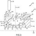
FIG. 3 is a cross sectional view of a lubricant scoop, in accordance with the invention; and -
FIG. 4 is a cross sectional view of a lubricant scoop and associated rotating component, in accordance with the invention. - All ranges may include the upper and lower values, and all ranges and ratio limits disclosed herein may be combined. It is to be understood that unless specifically stated otherwise, references to "a," "an," and/or "the" may include one or more than one and that reference to an item in the singular may also include the item in the plural.
- The detailed description of various embodiments herein makes reference to the accompanying drawings, which show various embodiments by way of illustration. While these various embodiments are described in sufficient detail to enable those skilled in the art to practice the disclosure, it should be understood that changes may be made without departing from the scope of the claims. Thus, the detailed description herein is presented for purposes of illustration only and not of limitation. Furthermore, any reference to singular includes plural embodiments, and any reference to more than one component or step may include a singular embodiment or step. Also, any reference to attached, fixed, connected, or the like may include permanent, removable, temporary, partial, full, and/or any other possible attachment option. Additionally, any reference to without contact (or similar phrases) may also include reduced contact or minimal contact.
-
FIG. 1 schematically illustrates a gas turbine engine 20. The gas turbine engine 20 is disclosed herein as a two-spool turbofan that generally incorporates afan section 22, acompressor section 24, acombustor section 26 and aturbine section 28. Alternative engines might include an augmenter section (not shown) among other systems or features. Thefan section 22 drives air along a bypass flow path B in a bypass duct defined within anacelle 15, while thecompressor section 24 drives air along a core or primary flow path C for compression and communication into thecombustor section 26 and then expansion through theturbine section 28. Although depicted as a two-spool turbofan gas turbine engine in the disclosed non-limiting embodiment, it should be understood that the concepts described herein are not limited to use with two-spool turbofans as the teachings may be applied to other types of turbine engines, including three-spool architectures. - The gas turbine engine 20 generally includes a
low speed spool 30 and ahigh speed spool 32 mounted for rotation about an engine central longitudinal axis A relative to an enginestatic structure 36 viaseveral bearing systems 38. It should be understood that various bearingsystems 38 at various locations may alternatively or additionally be provided and the location of the bearingsystems 38 may be varied as appropriate to the application. Thelow speed spool 30 generally includes aninner shaft 40 that interconnects afan 42, a first orlow pressure compressor 44 and a first orlow pressure turbine 46. Theinner shaft 40 is connected to thefan 42 through a speed change mechanism, which in this gas turbine engine 20 is illustrated as a gearedarchitecture 48 to drive thefan 42 at a lower speed than thelow speed spool 30. Thehigh speed spool 32 includes anouter shaft 50 that interconnects a second orhigh pressure compressor 52 and a second orhigh pressure turbine 54. Acombustor 56 is arranged in the gas turbine engine 20 between thehigh pressure compressor 52 and thehigh pressure turbine 54. Amid-turbine frame 57 of the enginestatic structure 36 is arranged generally between thehigh pressure turbine 54 and thelow pressure turbine 46. Themid-turbine frame 57 further supports the bearingsystems 38 in theturbine section 28. Theinner shaft 40 and theouter shaft 50 are concentric and rotate via the bearingsystems 38 about the engine central longitudinal axis A, which is collinear with their longitudinal axes. The bearing systems can be positioned in locations difficult to access for lubrication. - Referring now to
FIG. 2 , alubricant scoop 200 in accordance with the invention is illustrated. Thelubricant scoop 200 comprises anannular body 202. In various embodiments, thelubricant scoop 200 may be comprised of a single-component annular body. In various embodiments, thelubricant scoop 200 may be comprised of a multi-component annular body, such as a two-component annular body. In various embodiments, thelubricant scoop 200 comprises anannular body 202, which includes a firstannular portion 204 and a secondannular portion 206. In various embodiments, the firstannular portion 204 and the secondannular portion 206 comprise a single-component lubricant scoop. In various embodiments, the firstannular portion 204 comprises a first annular body and the secondannular portion 206 comprises a second annular body, the first and second annular bodies being separate components that, when positioned adjacent each other, form a two-component lubricant scoop. In various embodiments, the firstannular portion 204 and the secondannular portion 206 join together at asurface 210 extending radially through thelubricant scoop 200. Acentral axis 208 may run through the axial center of thelubricant scoop 200. - Referring now to
FIG. 3 , a cross section of alubricant scoop 300 is illustrated in accordance with the invention. Similar to the embodiment described above with reference toFIG. 2 , thelubricant scoop 300 comprises anannular body 302. In various embodiments, theannular body 302 comprises a firstannular portion 304 and a secondannular portion 306. In various embodiments, the firstannular portion 304 and the secondannular portion 306 comprise a single-component lubricant scoop. In various embodiments, the firstannular portion 304 comprises a first annular body and the secondannular portion 306 comprises a second annular body, the first and second annular bodies being separate components that, when positioned adjacent each other, form a two-component lubricant scoop. A central axis 308 may run through an axial center of thelubricant scoop 300. In various embodiments, aradial plane 310 separates theannular body 302 into the firstannular portion 304 and the secondannular portion 306. In various embodiments, theradial plane 310 may also define aninterface 316 between a firstannular body 312 and a secondannular body 314. In the description that follows, the same principles apply to embodiments having a single-component annular body, which may include the firstannular portion 304 and the secondannular portion 306, and to embodiments having a multi-component annular body, which may include the firstannular body 312 disposed adjacent the secondannular body 314. - In various embodiments, the first
annular portion 304 may include a radially orientedentrance surface 318 and a first axially orientedtransition surface 320. In various embodiments, the radially orientedentrance surface 318 includes a surface portion toward the radially outermost portion that is substantially radial with respect to the central axis 308 - i.e., a portion of the radially orientedentrance surface 318 at the radially outermost portion of the surface is substantially perpendicular to the central axis 308. In various embodiments, the first axially orientedtransition surface 320 includes a portion toward theinterface 316 orradial plane 310 that is substantially axial with respect to the central axis 308 - i.e., a portion of the first axially orientedtransition surface 320 closest theradial plane 310 is substantially parallel to the central axis 308. - In various embodiments, the radially oriented
entrance surface 318 and the first axially orientedtransition surface 320 intersect at afirst turning surface 326 defined by a radius ofcurvature 324. In various embodiments, the radius ofcurvature 324 and its radial origin may be selected to provide asurface 322 in the shape of a quarter-circle that provides a smooth and continuous transition from a radial direction at the radially orientedentrance surface 318 to an axial direction at the first axially orientedtransition surface 320. In various embodiments, a radius ofcurvature 328 and its radial origin may be selected to provide asurface 330 in the shape approaching a quarter-square that provides a sudden and abrupt transition from a radial direction at the radially orientedentrance surface 318 to an axial direction at the first axially orientedtransition surface 320. In the latter embodiments, the radius ofcurvature 328 has a value selected relatively small in comparison to a value for the radius ofcurvature 324 selected for the former embodiments. - Still referring to
FIG. 3 , the secondannular portion 306 may include a second axially orientedtransition surface 332 and a radially orientedexit surface 334. In various embodiments, the second axially orientedtransition surface 332 is sized and configured to mate smoothly with the first axially orientedtransition surface 320. In various embodiments, the first axially orientedtransition surface 320 intersects the second axially orientedtransition surface 332 at an intersection region where intersecting portions of both surfaces are coaxial with and parallel to the central axis 308, providing a smooth annular transition surface for fluid flow from the firstannular portion 304 to the secondannular portion 306. In various embodiments, the radially orientedexit surface 334 includes a surface portion toward a radially outermost portion that is substantially radial with respect to the central axis 308 - i.e., a portion of the radially orientedexit surface 334 at the radially outermost portion of the surface is substantially perpendicular to the central axis 308. In various embodiments, the second axially orientedtransition surface 332 includes a portion toward theinterface 316 orradial plane 310 that is substantially axial with respect to the central axis 308 - i.e., a portion of the second axially orientedtransition surface 332 closest theradial plane 310 is substantially parallel to the central axis 308. - In various embodiments, the radially oriented
exit surface 334 and the second axially orientedtransition surface 332 intersect at asecond turning surface 336 defined by a radius ofcurvature 338. Similar to the discussion above regarding the firstannular portion 304, in various embodiments, thesecond turning surface 336 may be selected to provide a surface in the shape of a quarter-circle that provides a smooth and continuous transition from an axial direction at the second axially orientedtransition surface 332 to a radial direction at the radially orientedexit surface 334. In various embodiments, the radius ofcurvature 338 and its radial origin may be selected to provide a surface in a shape approaching a quarter-square that provides a sudden and abrupt transition from an axial direction at the second axially orientedtransition surface 332 to a radial direction at the radially orientedexit surface 334. - Still referring to
FIG. 3 , the secondannular portion 306 may include aredirection member 340. In various embodiments, theredirection member 340 includes aprimary redirection member 342 and asecondary redirection member 344. Theredirection member 340 may extend in an axial direction from aproximal end 346 connected to the secondannular portion 306 proximate the radially orientedexit surface 334 to adistal end 348. In various embodiments, theprimary redirection member 342 includes thedistal end 348 and terminates at an axial location coincident with an axially location where the first axially orientedtransition surface 320 intersects or joins the second axially orientedtransition surface 332. In various embodiments, theprimary redirection member 342, including thedistal end 348, terminates at theradial plane 310 discussed above, which may be positioned at the same axial location where the first axially orientedtransition surface 320 intersects or joins the second axially orientedtransition surface 332. In various embodiments, thesecondary redirection member 344 is positioned at thedistal end 348 and extends radially inward of theprimary redirection member 342. - Still referring to
FIG. 3 , thelubricant scoop 300 includes acircumferential lubricant inlet 350. In various embodiments, thecircumferential lubricant inlet 350 is defined by a space or opening existing between the radially orientedentrance surface 318 and thedistal end 348 of theredirection member 340. In various embodiments, thecircumferential lubricant inlet 350 is defined by aninlet opening 352 existing between the radially orientedentrance surface 318 and thedistal end 348 of theredirection member 340 wherein theinlet opening 352 defines an annular plane that is coaxial with and parallel to the central axis 308. Thelubricant scoop 300 may also include anexit conduit 354. In various embodiments, theexit conduit 354 includes anopening 356 positioned at an intersection of theproximal end 346 of theredirection member 340 and the radially orientedexit surface 334. Theexit conduit 354 provides a passageway for lubrication fluid to flow from thelubricant scoop 300 to a rotating component. In various embodiments, a plurality ofexit conduits 354 is spaced circumferentially about thelubricant scoop 300. - In operation, as will be discussed further below, a
nozzle 358 directs a stream oflubricant 360 toward thecircumferential lubricant inlet 350 or inlet opening 352 in a generally radial direction with respect to the central axis 308. The stream oflubricant 360 is turned from a generally radial direction to a generally axial direction by the radially orientedentrance surface 318 of the firstannular portion 304, followed by thefirst turning surface 326, which transfers the lubricant to the first axially orientedtransition surface 320. Following passage from the firstannular portion 304 to the secondannular portion 306, via the first axially orientedtransition surface 320 of the firstannular portion 304 to the second axially orientedtransition surface 332 of the secondannular portion 306, the stream oflubricant 360 is turned from a generally axial direction to a generally radial direction by thesecond turning surface 336 toward the radially orientedexit surface 334. As the lubrication fluid approaches theredirection member 340, a portion of the fluid enters theexit conduit 354 for transport to a rotating component. The remaining portion of the lubrication fluid, if any, is redirected axially in a reverse direction - i.e., back toward the firstannular portion 304, where it is retained by centrifugal force. In various embodiments, theprimary redirection member 342 directs the lubrication fluid in the reverse axial direction and thesecondary redirection member 344 may direct the lubrication fluid radially inward to mix with incoming flow. In various embodiments, centrifugal force imparted to the fluid as it is directed along the radially orientedexit surface 334 as thelubricant scoop 300 rotates about the central axis 308 creates a pressure differential sufficient to force the lubrication fluid through theexit conduit 354 and into rotating componentry connected to theexit conduit 354. In various embodiments, theredirection member 340 retains lubricant proximate theexit conduit 354 due to centrifugal force imparted on the fluid as thelubricant scoop 300 rotates. In various embodiments, establishment and maintenance of fluid pressure proximate theopening 356 to theexit conduit 354 is a primary function of theredirection member 340, while radially inward redirection of lubricant is a secondary function. - Referring now to
FIG. 4 , a sectional view of alubrication system 400, comprising a rotating component and a lubricant scoop, such as found within the gas turbine engine illustrated inFIG. 1 , is provided. Thelubrication system 400 includes anaxle 402 configured to rotate about acentral axis 404. Alubricant scoop 406 is rotationally disposed on theaxle 402 together with a bearingassembly 408. Alubricant nozzle 450 provides a stream oflubricant 452 toward thelubricant scoop 406 for transport to rotating componentry, such as the bearingassembly 408. - In various embodiments, the
lubricant scoop 406 comprises anannular body 410. In various embodiments, theannular body 410 comprises a firstannular body 412 and a secondannular body 414. In various embodiments, the firstannular body 412 is an integral component separate and apart from the secondannular body 414, which is also an integral component separate and apart from the firstannular body 412. As described above, the same principles apply in this disclosure to embodiments having a single annular body and to embodiments having a multi-component annular body. In various embodiments, the bearingassembly 408 has aninner race 470 connected to and configured to rotate with theaxle 402 and anouter race 472 connected to a non-rotating portion of the gas turbine engine, such that theinner race 470 rotates relative to theouter race 472. A rolling or sliding element, such as aball bearing 474, is disposed between theinner race 470 and theouter race 472. In the description that follows, the same principles of operation and construction provided above apply with reference toFIG. 4 . - In operation, and in accordance with various embodiments, the
nozzle 450 directs the stream oflubricant 452 toward acircumferential lubricant inlet 416 in a generally radial direction with respect to thecentral axis 404. The stream oflubricant 452 is turned from a generally radial direction to a generally axial direction by a radially orientedentrance surface 418 followed by a first axially orientedtransition surface 420. Following passage from the first annular body 412 (or a first annular portion 422) to the second annular body 414 (or a second annular portion 424), the stream oflubricant 452 is turned from a generally axial direction to a generally radial direction by a second axially orientedtransition surface 426 followed by a radially orientedexit surface 428. As the lubrication fluid approaches aredirection member 430, a portion of the fluid enters anexit conduit 432 for transport to a rotating component, such as the bearingassembly 408. The remaining portion of the lubrication fluid, if any, is directed axially in a reverse direction - i.e., back toward the first annular body or first annular portion - and then radially inward. In various embodiments, aprimary redirection member 434 directs the lubrication fluid in the reverse axial direction and asecondary redirection 436 member directs the lubrication fluid radially inward to mix with incoming flow. - In various embodiments, centrifugal force imparted to the fluid as it is directed along the radially oriented
exit surface 428 as thelubricant scoop 406 rotates about thecentral axis 404 creates a pressure differential sufficient to force the lubrication fluid through theexit conduit 432 and into rotating componentry connected to theexit conduit 432, such as the bearingassembly 408. In various embodiments, theexit conduit 432 interfaces with adelivery conduit 438 disposed within theinner race 470 of the bearingassembly 408. Thedelivery conduit 438 routes lubrication fluid from theexit conduit 432 to theball bearing 474, providing lubrication to the bearingassembly 408. - The disclosure also provides a designer with configuration choices, such a single-piece lubrication scoop or a multiple-piece (e.g., a two-piece) lubrication scoop. The former configuration provides for reduced part count. The latter configuration - e.g., the two-piece configuration discussed above - may provide for improved manufacturability and reduced cost. Either configuration may provide for simplified assembly and disassembly of the oil scoop and engine, as well as simplified assembly tooling and design.
- Benefits, other advantages, and solutions to problems have been described herein with regard to specific embodiments. Furthermore, the connecting lines shown in the various figures contained herein are intended to represent exemplary functional relationships and/or physical couplings between the various elements. The scope of the disclosure is accordingly to be limited by nothing other than the appended claims, in which reference to an element in the singular is not intended to mean "one and only one" unless explicitly so stated, but rather "one or more." Moreover, where a phrase similar to "at least one of A, B, or C" is used in the claims, it is intended that the phrase be interpreted to mean that A alone may be present in an embodiment, B alone may be present in an embodiment, C alone may be present in an embodiment, or that any combination of the elements A, B and C may be present in a single embodiment; for example, A and B, A and C, B and C, or A and B and C. Different cross-hatching is used throughout the figures to denote different parts but not necessarily to denote the same or different materials.
Claims (14)
- A lubricant scoop (200, 300, 400), comprising:an annular body (202, 302, 410) configured for engagement with a shaft rotating about a central axis (208, 308, 404), the annular body (202, 302, 410) including
a first annular portion (204, 304, 412) having a radially oriented entrance surface (318, 418) and a first axially oriented transition surface (320, 420) and
a second annular portion (206, 306, 414) disposed adjacent the first annular portion (204, 304, 412) and having a second axially oriented transition surface (332, 426), a primary redirection member (342, 434) spaced radially outward from the second axially oriented transition surface (332, 426), a radially oriented exit surface (334, 428) and an exit conduit (354, 432) having an opening (356) positioned proximate the radially oriented exit surface (334, 428),wherein the first annular portion (204, 304, 412) includes a circumferential lubricant inlet (350, 416) defined by a space between the radially oriented entrance surface (318, 418) and the primary redirection member (342, 434). - The lubricant scoop of claim 1, wherein the circumferential lubricant inlet (350, 416) is defined by an annular plane coaxial with and parallel to the central axis (308, 404).
- The lubricant scoop of claim 1 or 2, wherein the first axially oriented transition surface (320, 420) intersects the second axially oriented transition surface(332, 426) at an intersection region where intersecting portions of both surfaces are coaxial with and parallel to the central axis (308, 404).
- The lubricant scoop of any preceding claim, wherein the radially oriented entrance surface (318, 418) and the first axially oriented transition surface (320, 420) intersect at a first portion having a first turning surface (326) defined by a first radius of curvature.
- The lubricant scoop of any preceding claim, wherein the second axially oriented transition surface (332, 426) and the radially oriented exit surface (334, 428) intersect at a second portion having a second turning surface (336) defined by a second radius of curvature.
- The lubricant scoop of any preceding claim, wherein a radially outermost portion of the radially oriented entrance surface (334, 428) is defined by a radial plane disposed perpendicular to the central axis (308, 404).
- The lubricant scoop of any preceding claim, wherein the primary redirection member (342, 434) is an annular member that extends axially from the second annular portion (206, 306, 414) toward the first annular portion (204, 304, 412).
- The lubricant scoop of claim 7, wherein the primary redirection member (342, 434) has a proximal end connected to the second annular portion (204, 304, 414) radially outward of the opening to the exit conduit (354, 432).
- A lubricant scoop according to any of the preceding claims
wherein the first annular portion is a first annular body (412) configured for engagement with the shaft, the first annular body (412) including a radially oriented entrance surface (418) and a first axially oriented transition surface (420) and
wherein the second annular portion is a second annular body (414) configured for engagement with the shaft, the second annular body (414) comprising a second axially oriented transition surface (420), a primary redirection member (434) spaced radially outward from the second axially oriented transition surface (426), a radially oriented exit surface (428) and an exit conduit (432) having an opening positioned on the radially oriented exit surface (428),
wherein the second annular body is configured for positioning adjacent the first annular body such that the second axially oriented transition surface intersects with the first axially oriented transition surface. - The lubricant scoop of claim 9, wherein the primary redirection member (434) is an annular member that extends axially from the second annular body (414) toward the first annular body (412).
- The lubricant scoop of claim 10, wherein the primary redirection member (434) has a proximal end connected to the second annular body (414) radially outward of the opening to the exit conduit (432).
- The lubricant scoop of claim 8 or 11, wherein the primary redirection member (342, 434) has a distal end that terminates at an axial location coincident with an axially location where the first axially oriented transition surface (320, 420) intersects the second axially oriented transition surface (322, 426).
- The lubricant scoop of claim 10, wherein the distal end of the primary redirection member (342, 434) includes a secondary redirection member (344) directed radially inward of the primary redirection member.
- A gas turbine engine, comprising:a shaft (402) configured to rotate about a central axis (208, 308, 404);a rotating component configured to rotate with the shaft;a lubricant scoop (200, 300, 406) as claimed in any preceding claim,
wherein the annular body (202, 302, 410) is engaged with the shaft, wherein the exit conduit (354, 432) having an opening is positioned on the radially oriented exit surface (334, 428), wherein the exit conduit (354, 432)is configured to communicate lubricant to the rotating component; anda lubricant spray nozzle (450) directed toward a circumferential lubricant inlet (416) defined by a space between the radially oriented entrance surface (318, 418) and the primary redirection member (342, 434).
Applications Claiming Priority (1)
| Application Number | Priority Date | Filing Date | Title |
|---|---|---|---|
| US15/789,469 US10662812B2 (en) | 2017-10-20 | 2017-10-20 | Lubricant scoop |
Publications (2)
| Publication Number | Publication Date |
|---|---|
| EP3473914A1 EP3473914A1 (en) | 2019-04-24 |
| EP3473914B1 true EP3473914B1 (en) | 2020-05-27 |
Family
ID=63878571
Family Applications (1)
| Application Number | Title | Priority Date | Filing Date |
|---|---|---|---|
| EP18201047.0A Active EP3473914B1 (en) | 2017-10-20 | 2018-10-17 | Lubricant scoop |
Country Status (2)
| Country | Link |
|---|---|
| US (1) | US10662812B2 (en) |
| EP (1) | EP3473914B1 (en) |
Families Citing this family (7)
| Publication number | Priority date | Publication date | Assignee | Title |
|---|---|---|---|---|
| GB201805180D0 (en) * | 2018-03-29 | 2018-05-16 | Rolls Royce Plc | Oil distribution assembly |
| US11209086B2 (en) * | 2018-10-29 | 2021-12-28 | Raytheon Technologies Corporation | Wet-face/dry-face seal and methods of operation |
| US11286854B2 (en) * | 2019-08-08 | 2022-03-29 | Raytheon Technologies Corporation | Ducted oil scoop for gas turbine engine |
| US11852029B2 (en) | 2020-08-14 | 2023-12-26 | Rtx Corporation | Scoop assembly for rotational equipment |
| CN115717629B (en) * | 2022-11-25 | 2025-07-15 | 中国船舶集团有限公司第七0三研究所 | An under-ring oil supply ring for high-speed rolling bearing |
| US20250251020A1 (en) * | 2024-02-06 | 2025-08-07 | Rtx Corporation | Oil lubrication fan persuader |
| CN119021986A (en) * | 2024-10-21 | 2024-11-26 | 马鞍山易联仓储科技有限公司 | A bearing with automatic quantitative lubrication for conveying equipment |
Family Cites Families (21)
| Publication number | Priority date | Publication date | Assignee | Title |
|---|---|---|---|---|
| GB821346A (en) | 1955-11-14 | 1959-10-07 | United Aircraft Corp | Lubricating means |
| US2878894A (en) * | 1955-11-14 | 1959-03-24 | United Aircraft Corp | Lubricating means |
| GB858550A (en) | 1956-10-22 | 1961-01-11 | Sulzer Ag | Centrifugal pumps |
| US2956824A (en) | 1957-12-27 | 1960-10-18 | Koppers Co Inc | Vented shaft seal |
| GB922415A (en) | 1958-09-22 | 1963-04-03 | American Radiator & Standard | Improvements in or relating to fluid couplings |
| US3195682A (en) * | 1962-12-21 | 1965-07-20 | Ford Motor Co | Lubricating means for bearings |
| US4342489A (en) * | 1980-10-07 | 1982-08-03 | Teledyne Industries, Inc. | Bearing lubricating injector |
| DE3500955A1 (en) | 1985-01-14 | 1986-07-17 | Klein, Schanzlin & Becker Ag, 6710 Frankenthal | DEVICE FOR THE OIL SUPPLY OF HORIZONTALLY POSITIONED POWER AND WORKING MACHINES |
| US4648485A (en) * | 1985-10-04 | 1987-03-10 | United Technologies Corporation | Radial scoop construction |
| US6409464B1 (en) * | 2000-06-30 | 2002-06-25 | General Electric Company | Methods and apparatus for supplying oil to bearing assemblies |
| US6682222B2 (en) * | 2001-08-22 | 2004-01-27 | General Electric Company | Bi-directional oil scoop for bearing lubrication |
| US6735956B2 (en) * | 2001-10-26 | 2004-05-18 | Pratt & Whitney Canada Corp. | High pressure turbine blade cooling scoop |
| US7244096B2 (en) * | 2005-05-19 | 2007-07-17 | Honeywell International, Inc. | Curved blade oil scoop |
| DE102006055808B4 (en) | 2006-11-27 | 2008-08-21 | Gkn Driveline International Gmbh | Oil scoop arrangement for supplying oil to rotating machine components |
| US8464835B2 (en) * | 2008-08-15 | 2013-06-18 | Rolls-Royce Corporation | Lubricant scoop |
| US9631508B2 (en) | 2013-06-13 | 2017-04-25 | Pratt & Whitney Canada Corp. | Internally cooled seal runner |
| US9797268B2 (en) * | 2015-03-27 | 2017-10-24 | United Technologies Corporation | Oil scoop with integrated sensor |
| US9732630B2 (en) * | 2015-03-27 | 2017-08-15 | United Technologies Corporation | Oil scoop and shaft with axially-oriented hole |
| US9726040B2 (en) * | 2015-03-27 | 2017-08-08 | Pratt & Whitney Canada Corp. | Fluid delivery system for a gas turbine engine |
| US9989083B2 (en) * | 2015-05-26 | 2018-06-05 | Pratt & Whitney Canada Corp. | Seal and bearing assembly for a gas turbine engine and method of assembling same |
| US10174629B1 (en) * | 2017-09-11 | 2019-01-08 | United Technologies Corporation | Phonic seal seat |
-
2017
- 2017-10-20 US US15/789,469 patent/US10662812B2/en active Active
-
2018
- 2018-10-17 EP EP18201047.0A patent/EP3473914B1/en active Active
Non-Patent Citations (1)
| Title |
|---|
| None * |
Also Published As
| Publication number | Publication date |
|---|---|
| EP3473914A1 (en) | 2019-04-24 |
| US20190120085A1 (en) | 2019-04-25 |
| US10662812B2 (en) | 2020-05-26 |
Similar Documents
| Publication | Publication Date | Title |
|---|---|---|
| US10662812B2 (en) | Lubricant scoop | |
| US10935076B2 (en) | Journal bearing assembly with dual oil cavities | |
| EP2554874B1 (en) | Journal pin oil supply for gear system and method for assembling | |
| EP2574805B1 (en) | Bearing oiling system | |
| JP6525193B2 (en) | Planetary transmission provided with a lubrication system | |
| EP2766621B1 (en) | Dynamically-lubricated bearing and method of dynamically lubricating a bearing | |
| EP3444442B1 (en) | Turbomachine comprising a bearing centering spring and damper and corresponding using method | |
| EP3001072B1 (en) | Oil transfer bearing and oil transfer method | |
| US10851671B2 (en) | Bending stiffening feature used for compliant journal bearing | |
| US8789656B2 (en) | Shaft bearing lubricant aerator, system, and method | |
| EP2093440B1 (en) | Bearing system | |
| WO2015026600A1 (en) | Reduced misalignment gear system | |
| EP3401514B1 (en) | Fluid damping structure ring and method of fluid damping | |
| EP3650721B1 (en) | Centering spring for gas turbine engine bearing compartment | |
| EP2886894B1 (en) | Mechanical device comprising a bearing and a lubrication system, implementing machine and method | |
| US9726039B2 (en) | Oil transfer system on rotating shaft | |
| US20220213956A1 (en) | Planet carrier for a mechanical gearbox of an aircraft turbomachine | |
| EP3070303B1 (en) | Turbocharger comprising a flinger and insert | |
| EP3626985B1 (en) | Ball bearing with lubricant drain | |
| EP3741962B1 (en) | Cover for rotatable shaft of gas turbine engine | |
| US12203382B1 (en) | Bearing oil distribution scheme | |
| CN122055565A (en) | Multiple fluid delivery device having a collar, sleeve and ring disposed at a peripheral portion thereof that collectively define a fluid path |
Legal Events
| Date | Code | Title | Description |
|---|---|---|---|
| PUAI | Public reference made under article 153(3) epc to a published international application that has entered the european phase |
Free format text: ORIGINAL CODE: 0009012 |
|
| STAA | Information on the status of an ep patent application or granted ep patent |
Free format text: STATUS: THE APPLICATION HAS BEEN PUBLISHED |
|
| AK | Designated contracting states |
Kind code of ref document: A1 Designated state(s): AL AT BE BG CH CY CZ DE DK EE ES FI FR GB GR HR HU IE IS IT LI LT LU LV MC MK MT NL NO PL PT RO RS SE SI SK SM TR |
|
| AX | Request for extension of the european patent |
Extension state: BA ME |
|
| RIN1 | Information on inventor provided before grant (corrected) |
Inventor name: WALKER, JOSEPH D. Inventor name: COFFIN, JAMES B. |
|
| STAA | Information on the status of an ep patent application or granted ep patent |
Free format text: STATUS: REQUEST FOR EXAMINATION WAS MADE |
|
| 17P | Request for examination filed |
Effective date: 20191022 |
|
| RBV | Designated contracting states (corrected) |
Designated state(s): AL AT BE BG CH CY CZ DE DK EE ES FI FR GB GR HR HU IE IS IT LI LT LU LV MC MK MT NL NO PL PT RO RS SE SI SK SM TR |
|
| GRAP | Despatch of communication of intention to grant a patent |
Free format text: ORIGINAL CODE: EPIDOSNIGR1 |
|
| STAA | Information on the status of an ep patent application or granted ep patent |
Free format text: STATUS: GRANT OF PATENT IS INTENDED |
|
| INTG | Intention to grant announced |
Effective date: 20191129 |
|
| GRAS | Grant fee paid |
Free format text: ORIGINAL CODE: EPIDOSNIGR3 |
|
| GRAJ | Information related to disapproval of communication of intention to grant by the applicant or resumption of examination proceedings by the epo deleted |
Free format text: ORIGINAL CODE: EPIDOSDIGR1 |
|
| GRAL | Information related to payment of fee for publishing/printing deleted |
Free format text: ORIGINAL CODE: EPIDOSDIGR3 |
|
| STAA | Information on the status of an ep patent application or granted ep patent |
Free format text: STATUS: REQUEST FOR EXAMINATION WAS MADE |
|
| GRAJ | Information related to disapproval of communication of intention to grant by the applicant or resumption of examination proceedings by the epo deleted |
Free format text: ORIGINAL CODE: EPIDOSDIGR1 |
|
| GRAP | Despatch of communication of intention to grant a patent |
Free format text: ORIGINAL CODE: EPIDOSNIGR1 |
|
| GRAR | Information related to intention to grant a patent recorded |
Free format text: ORIGINAL CODE: EPIDOSNIGR71 |
|
| STAA | Information on the status of an ep patent application or granted ep patent |
Free format text: STATUS: GRANT OF PATENT IS INTENDED |
|
| GRAA | (expected) grant |
Free format text: ORIGINAL CODE: 0009210 |
|
| STAA | Information on the status of an ep patent application or granted ep patent |
Free format text: STATUS: THE PATENT HAS BEEN GRANTED |
|
| INTC | Intention to grant announced (deleted) | ||
| AK | Designated contracting states |
Kind code of ref document: B1 Designated state(s): AL AT BE BG CH CY CZ DE DK EE ES FI FR GB GR HR HU IE IS IT LI LT LU LV MC MK MT NL NO PL PT RO RS SE SI SK SM TR |
|
| INTG | Intention to grant announced |
Effective date: 20200420 |
|
| REG | Reference to a national code |
Ref country code: GB Ref legal event code: FG4D |
|
| REG | Reference to a national code |
Ref country code: CH Ref legal event code: EP |
|
| REG | Reference to a national code |
Ref country code: AT Ref legal event code: REF Ref document number: 1274919 Country of ref document: AT Kind code of ref document: T Effective date: 20200615 |
|
| REG | Reference to a national code |
Ref country code: DE Ref legal event code: R096 Ref document number: 602018004889 Country of ref document: DE |
|
| REG | Reference to a national code |
Ref country code: LT Ref legal event code: MG4D |
|
| PG25 | Lapsed in a contracting state [announced via postgrant information from national office to epo] |
Ref country code: GR Free format text: LAPSE BECAUSE OF FAILURE TO SUBMIT A TRANSLATION OF THE DESCRIPTION OR TO PAY THE FEE WITHIN THE PRESCRIBED TIME-LIMIT Effective date: 20200828 Ref country code: NO Free format text: LAPSE BECAUSE OF FAILURE TO SUBMIT A TRANSLATION OF THE DESCRIPTION OR TO PAY THE FEE WITHIN THE PRESCRIBED TIME-LIMIT Effective date: 20200827 Ref country code: SE Free format text: LAPSE BECAUSE OF FAILURE TO SUBMIT A TRANSLATION OF THE DESCRIPTION OR TO PAY THE FEE WITHIN THE PRESCRIBED TIME-LIMIT Effective date: 20200527 Ref country code: PT Free format text: LAPSE BECAUSE OF FAILURE TO SUBMIT A TRANSLATION OF THE DESCRIPTION OR TO PAY THE FEE WITHIN THE PRESCRIBED TIME-LIMIT Effective date: 20200928 Ref country code: IS Free format text: LAPSE BECAUSE OF FAILURE TO SUBMIT A TRANSLATION OF THE DESCRIPTION OR TO PAY THE FEE WITHIN THE PRESCRIBED TIME-LIMIT Effective date: 20200927 Ref country code: FI Free format text: LAPSE BECAUSE OF FAILURE TO SUBMIT A TRANSLATION OF THE DESCRIPTION OR TO PAY THE FEE WITHIN THE PRESCRIBED TIME-LIMIT Effective date: 20200527 Ref country code: LT Free format text: LAPSE BECAUSE OF FAILURE TO SUBMIT A TRANSLATION OF THE DESCRIPTION OR TO PAY THE FEE WITHIN THE PRESCRIBED TIME-LIMIT Effective date: 20200527 |
|
| REG | Reference to a national code |
Ref country code: NL Ref legal event code: MP Effective date: 20200527 |
|
| PG25 | Lapsed in a contracting state [announced via postgrant information from national office to epo] |
Ref country code: HR Free format text: LAPSE BECAUSE OF FAILURE TO SUBMIT A TRANSLATION OF THE DESCRIPTION OR TO PAY THE FEE WITHIN THE PRESCRIBED TIME-LIMIT Effective date: 20200527 Ref country code: LV Free format text: LAPSE BECAUSE OF FAILURE TO SUBMIT A TRANSLATION OF THE DESCRIPTION OR TO PAY THE FEE WITHIN THE PRESCRIBED TIME-LIMIT Effective date: 20200527 Ref country code: BG Free format text: LAPSE BECAUSE OF FAILURE TO SUBMIT A TRANSLATION OF THE DESCRIPTION OR TO PAY THE FEE WITHIN THE PRESCRIBED TIME-LIMIT Effective date: 20200827 Ref country code: RS Free format text: LAPSE BECAUSE OF FAILURE TO SUBMIT A TRANSLATION OF THE DESCRIPTION OR TO PAY THE FEE WITHIN THE PRESCRIBED TIME-LIMIT Effective date: 20200527 |
|
| REG | Reference to a national code |
Ref country code: AT Ref legal event code: MK05 Ref document number: 1274919 Country of ref document: AT Kind code of ref document: T Effective date: 20200527 |
|
| PG25 | Lapsed in a contracting state [announced via postgrant information from national office to epo] |
Ref country code: NL Free format text: LAPSE BECAUSE OF FAILURE TO SUBMIT A TRANSLATION OF THE DESCRIPTION OR TO PAY THE FEE WITHIN THE PRESCRIBED TIME-LIMIT Effective date: 20200527 Ref country code: AL Free format text: LAPSE BECAUSE OF FAILURE TO SUBMIT A TRANSLATION OF THE DESCRIPTION OR TO PAY THE FEE WITHIN THE PRESCRIBED TIME-LIMIT Effective date: 20200527 |
|
| PG25 | Lapsed in a contracting state [announced via postgrant information from national office to epo] |
Ref country code: ES Free format text: LAPSE BECAUSE OF FAILURE TO SUBMIT A TRANSLATION OF THE DESCRIPTION OR TO PAY THE FEE WITHIN THE PRESCRIBED TIME-LIMIT Effective date: 20200527 Ref country code: CZ Free format text: LAPSE BECAUSE OF FAILURE TO SUBMIT A TRANSLATION OF THE DESCRIPTION OR TO PAY THE FEE WITHIN THE PRESCRIBED TIME-LIMIT Effective date: 20200527 Ref country code: DK Free format text: LAPSE BECAUSE OF FAILURE TO SUBMIT A TRANSLATION OF THE DESCRIPTION OR TO PAY THE FEE WITHIN THE PRESCRIBED TIME-LIMIT Effective date: 20200527 Ref country code: AT Free format text: LAPSE BECAUSE OF FAILURE TO SUBMIT A TRANSLATION OF THE DESCRIPTION OR TO PAY THE FEE WITHIN THE PRESCRIBED TIME-LIMIT Effective date: 20200527 Ref country code: EE Free format text: LAPSE BECAUSE OF FAILURE TO SUBMIT A TRANSLATION OF THE DESCRIPTION OR TO PAY THE FEE WITHIN THE PRESCRIBED TIME-LIMIT Effective date: 20200527 Ref country code: IT Free format text: LAPSE BECAUSE OF FAILURE TO SUBMIT A TRANSLATION OF THE DESCRIPTION OR TO PAY THE FEE WITHIN THE PRESCRIBED TIME-LIMIT Effective date: 20200527 Ref country code: SM Free format text: LAPSE BECAUSE OF FAILURE TO SUBMIT A TRANSLATION OF THE DESCRIPTION OR TO PAY THE FEE WITHIN THE PRESCRIBED TIME-LIMIT Effective date: 20200527 Ref country code: RO Free format text: LAPSE BECAUSE OF FAILURE TO SUBMIT A TRANSLATION OF THE DESCRIPTION OR TO PAY THE FEE WITHIN THE PRESCRIBED TIME-LIMIT Effective date: 20200527 |
|
| PG25 | Lapsed in a contracting state [announced via postgrant information from national office to epo] |
Ref country code: SK Free format text: LAPSE BECAUSE OF FAILURE TO SUBMIT A TRANSLATION OF THE DESCRIPTION OR TO PAY THE FEE WITHIN THE PRESCRIBED TIME-LIMIT Effective date: 20200527 Ref country code: PL Free format text: LAPSE BECAUSE OF FAILURE TO SUBMIT A TRANSLATION OF THE DESCRIPTION OR TO PAY THE FEE WITHIN THE PRESCRIBED TIME-LIMIT Effective date: 20200527 |
|
| REG | Reference to a national code |
Ref country code: DE Ref legal event code: R097 Ref document number: 602018004889 Country of ref document: DE |
|
| RAP2 | Party data changed (patent owner data changed or rights of a patent transferred) |
Owner name: RAYTHEON TECHNOLOGIES CORPORATION |
|
| PLBE | No opposition filed within time limit |
Free format text: ORIGINAL CODE: 0009261 |
|
| STAA | Information on the status of an ep patent application or granted ep patent |
Free format text: STATUS: NO OPPOSITION FILED WITHIN TIME LIMIT |
|
| 26N | No opposition filed |
Effective date: 20210302 |
|
| PG25 | Lapsed in a contracting state [announced via postgrant information from national office to epo] |
Ref country code: SI Free format text: LAPSE BECAUSE OF FAILURE TO SUBMIT A TRANSLATION OF THE DESCRIPTION OR TO PAY THE FEE WITHIN THE PRESCRIBED TIME-LIMIT Effective date: 20200527 |
|
| PG25 | Lapsed in a contracting state [announced via postgrant information from national office to epo] |
Ref country code: LU Free format text: LAPSE BECAUSE OF NON-PAYMENT OF DUE FEES Effective date: 20201017 Ref country code: MC Free format text: LAPSE BECAUSE OF FAILURE TO SUBMIT A TRANSLATION OF THE DESCRIPTION OR TO PAY THE FEE WITHIN THE PRESCRIBED TIME-LIMIT Effective date: 20200527 |
|
| REG | Reference to a national code |
Ref country code: BE Ref legal event code: MM Effective date: 20201031 |
|
| PG25 | Lapsed in a contracting state [announced via postgrant information from national office to epo] |
Ref country code: BE Free format text: LAPSE BECAUSE OF NON-PAYMENT OF DUE FEES Effective date: 20201031 |
|
| PG25 | Lapsed in a contracting state [announced via postgrant information from national office to epo] |
Ref country code: IE Free format text: LAPSE BECAUSE OF NON-PAYMENT OF DUE FEES Effective date: 20201017 |
|
| REG | Reference to a national code |
Ref country code: CH Ref legal event code: PL |
|
| PG25 | Lapsed in a contracting state [announced via postgrant information from national office to epo] |
Ref country code: TR Free format text: LAPSE BECAUSE OF FAILURE TO SUBMIT A TRANSLATION OF THE DESCRIPTION OR TO PAY THE FEE WITHIN THE PRESCRIBED TIME-LIMIT Effective date: 20200527 Ref country code: MT Free format text: LAPSE BECAUSE OF FAILURE TO SUBMIT A TRANSLATION OF THE DESCRIPTION OR TO PAY THE FEE WITHIN THE PRESCRIBED TIME-LIMIT Effective date: 20200527 Ref country code: CY Free format text: LAPSE BECAUSE OF FAILURE TO SUBMIT A TRANSLATION OF THE DESCRIPTION OR TO PAY THE FEE WITHIN THE PRESCRIBED TIME-LIMIT Effective date: 20200527 |
|
| PG25 | Lapsed in a contracting state [announced via postgrant information from national office to epo] |
Ref country code: MK Free format text: LAPSE BECAUSE OF FAILURE TO SUBMIT A TRANSLATION OF THE DESCRIPTION OR TO PAY THE FEE WITHIN THE PRESCRIBED TIME-LIMIT Effective date: 20200527 |
|
| PG25 | Lapsed in a contracting state [announced via postgrant information from national office to epo] |
Ref country code: LI Free format text: LAPSE BECAUSE OF NON-PAYMENT OF DUE FEES Effective date: 20211031 Ref country code: CH Free format text: LAPSE BECAUSE OF NON-PAYMENT OF DUE FEES Effective date: 20211031 |
|
| P01 | Opt-out of the competence of the unified patent court (upc) registered |
Effective date: 20230521 |
|
| REG | Reference to a national code |
Ref country code: DE Ref legal event code: R081 Ref document number: 602018004889 Country of ref document: DE Owner name: RTX CORPORATION (N.D.GES.D. STAATES DELAWARE),, US Free format text: FORMER OWNER: UNITED TECHNOLOGIES CORPORATION, FARMINGTON, CONN., US |
|
| PGFP | Annual fee paid to national office [announced via postgrant information from national office to epo] |
Ref country code: GB Payment date: 20250923 Year of fee payment: 8 |
|
| PGFP | Annual fee paid to national office [announced via postgrant information from national office to epo] |
Ref country code: FR Payment date: 20250924 Year of fee payment: 8 |
|
| PGFP | Annual fee paid to national office [announced via postgrant information from national office to epo] |
Ref country code: DE Payment date: 20250923 Year of fee payment: 8 |