EP3473910A1 - Duct assembly having internal noise reduction features, thermal insulation and leak detection - Google Patents
Duct assembly having internal noise reduction features, thermal insulation and leak detection Download PDFInfo
- Publication number
- EP3473910A1 EP3473910A1 EP18201988.5A EP18201988A EP3473910A1 EP 3473910 A1 EP3473910 A1 EP 3473910A1 EP 18201988 A EP18201988 A EP 18201988A EP 3473910 A1 EP3473910 A1 EP 3473910A1
- Authority
- EP
- European Patent Office
- Prior art keywords
- duct
- wall
- resonator
- cavity
- throat
- Prior art date
- Legal status (The legal status is an assumption and is not a legal conclusion. Google has not performed a legal analysis and makes no representation as to the accuracy of the status listed.)
- Granted
Links
Images

Classifications
-
- F—MECHANICAL ENGINEERING; LIGHTING; HEATING; WEAPONS; BLASTING
- F16—ENGINEERING ELEMENTS AND UNITS; GENERAL MEASURES FOR PRODUCING AND MAINTAINING EFFECTIVE FUNCTIONING OF MACHINES OR INSTALLATIONS; THERMAL INSULATION IN GENERAL
- F16L—PIPES; JOINTS OR FITTINGS FOR PIPES; SUPPORTS FOR PIPES, CABLES OR PROTECTIVE TUBING; MEANS FOR THERMAL INSULATION IN GENERAL
- F16L55/00—Devices or appurtenances for use in, or in connection with, pipes or pipe systems
- F16L55/02—Energy absorbers; Noise absorbers
- F16L55/033—Noise absorbers
-
- B—PERFORMING OPERATIONS; TRANSPORTING
- B33—ADDITIVE MANUFACTURING TECHNOLOGY
- B33Y—ADDITIVE MANUFACTURING, i.e. MANUFACTURING OF THREE-DIMENSIONAL [3D] OBJECTS BY ADDITIVE DEPOSITION, ADDITIVE AGGLOMERATION OR ADDITIVE LAYERING, e.g. BY 3D PRINTING, STEREOLITHOGRAPHY OR SELECTIVE LASER SINTERING
- B33Y80/00—Products made by additive manufacturing
-
- B—PERFORMING OPERATIONS; TRANSPORTING
- B64—AIRCRAFT; AVIATION; COSMONAUTICS
- B64D—EQUIPMENT FOR FITTING IN OR TO AIRCRAFT; FLIGHT SUITS; PARACHUTES; ARRANGEMENT OR MOUNTING OF POWER PLANTS OR PROPULSION TRANSMISSIONS IN AIRCRAFT
- B64D13/00—Arrangements or adaptations of air-treatment apparatus for aircraft crew or passengers, or freight space
-
- F—MECHANICAL ENGINEERING; LIGHTING; HEATING; WEAPONS; BLASTING
- F16—ENGINEERING ELEMENTS AND UNITS; GENERAL MEASURES FOR PRODUCING AND MAINTAINING EFFECTIVE FUNCTIONING OF MACHINES OR INSTALLATIONS; THERMAL INSULATION IN GENERAL
- F16L—PIPES; JOINTS OR FITTINGS FOR PIPES; SUPPORTS FOR PIPES, CABLES OR PROTECTIVE TUBING; MEANS FOR THERMAL INSULATION IN GENERAL
- F16L9/00—Rigid pipes
- F16L9/18—Double-walled pipes; Multi-channel pipes or pipe assemblies
-
- F—MECHANICAL ENGINEERING; LIGHTING; HEATING; WEAPONS; BLASTING
- F16—ENGINEERING ELEMENTS AND UNITS; GENERAL MEASURES FOR PRODUCING AND MAINTAINING EFFECTIVE FUNCTIONING OF MACHINES OR INSTALLATIONS; THERMAL INSULATION IN GENERAL
- F16L—PIPES; JOINTS OR FITTINGS FOR PIPES; SUPPORTS FOR PIPES, CABLES OR PROTECTIVE TUBING; MEANS FOR THERMAL INSULATION IN GENERAL
- F16L9/00—Rigid pipes
- F16L9/18—Double-walled pipes; Multi-channel pipes or pipe assemblies
- F16L9/19—Multi-channel pipes or pipe assemblies
-
- F—MECHANICAL ENGINEERING; LIGHTING; HEATING; WEAPONS; BLASTING
- F16—ENGINEERING ELEMENTS AND UNITS; GENERAL MEASURES FOR PRODUCING AND MAINTAINING EFFECTIVE FUNCTIONING OF MACHINES OR INSTALLATIONS; THERMAL INSULATION IN GENERAL
- F16L—PIPES; JOINTS OR FITTINGS FOR PIPES; SUPPORTS FOR PIPES, CABLES OR PROTECTIVE TUBING; MEANS FOR THERMAL INSULATION IN GENERAL
- F16L2201/00—Special arrangements for pipe couplings
- F16L2201/30—Detecting leaks
-
- F—MECHANICAL ENGINEERING; LIGHTING; HEATING; WEAPONS; BLASTING
- F16—ENGINEERING ELEMENTS AND UNITS; GENERAL MEASURES FOR PRODUCING AND MAINTAINING EFFECTIVE FUNCTIONING OF MACHINES OR INSTALLATIONS; THERMAL INSULATION IN GENERAL
- F16L—PIPES; JOINTS OR FITTINGS FOR PIPES; SUPPORTS FOR PIPES, CABLES OR PROTECTIVE TUBING; MEANS FOR THERMAL INSULATION IN GENERAL
- F16L55/00—Devices or appurtenances for use in, or in connection with, pipes or pipe systems
- F16L55/02—Energy absorbers; Noise absorbers
- F16L55/027—Throttle passages
- F16L55/02781—The regulating element being provided with radial outputs
Definitions
- Exemplary embodiments pertain to the art of duct assemblies having internal noise reduction features.
- a fluid flow within a pipe may produce noise.
- Typical methods to reduce this flow induced noise may include noise reduction treatments that are disposed about or disposed within the pipe. These noise reduction treatments are not tuned to attenuate a specific frequency, are often heavy or bulky, and may deteriorate in service. Accordingly, it is desirable to provide a more compact and efficient noise reduction mechanism for a pipe.
- a duct assembly that includes a first duct.
- the first duct has a first inner wall and a first outer wall each extending between a first duct first end and a first duct second end.
- the first duct defines a first duct first resonator that extends between the first inner wall and the first outer wall.
- the first inner wall defines a first flow path.
- the first duct first resonator includes a first opening that extends through the first inner wall, a first cavity defined between the first inner wall and the first outer wall, and a first throat extending between the first opening and the first cavity.
- the first duct defines a first duct second resonator that is spaced apart from the first duct first resonator.
- the first duct second resonator includes a second opening that extends through the first inner wall, a second cavity defined between the first inner wall and the first outer wall, and a second throat extending between the second opening and the second cavity.
- the first cavity has a first volume and the second cavity has a second volume.
- the first volume is different from the second volume.
- a second duct that is disposed about the first duct.
- the second duct has a second inner wall that is spaced apart from the first outer wall and a second outer wall, each extending between a second duct first end and a second duct second end.
- the second duct defines a port that extends from the second inner wall to the second outer wall.
- a support member extends between the first outer wall and the second inner wall, spacing the second duct apart from the first duct.
- an insulating air gap is defined between the first outer wall of the first duct and the second inner wall of the second duct.
- the duct assembly includes a first duct and a second duct.
- the first duct has a first inner wall and a first outer wall.
- the first duct defines a first duct first resonator that is defined between the first inner wall and the first outer wall.
- the second duct is disposed about the first duct.
- the second duct has a second inner wall and a second outer wall.
- the first duct is spaced apart from the second duct by a support member that extends between the first outer wall and the second inner wall.
- the first inner wall defines a first flow path.
- an insulating air gap is defined between the first outer wall of the first duct and the second inner wall of the second duct.
- the second duct defines a second duct first resonator that is defined between the second inner wall and the second outer wall.
- the duct assembly includes a first duct, a second duct, and a support member.
- the first duct has a first inner wall and a first outer wall.
- the first duct defines a first duct first resonator that is defined between the first inner wall and the first outer wall.
- the second duct has a second inner wall and a second outer wall.
- the second duct defines a second duct first resonator that is defined between the second inner wall and the second outer wall.
- the support member extends between and is connected to the first outer wall and the second inner wall.
- the first duct first resonator includes a first cavity having a first volume and the second duct first resonator includes a second cavity having a second volume.
- the first volume is different from the second volume.
- the second duct defines a port that extends from the second inner wall to the second outer wall.
- a leakage detection sensor is operatively connected to the port.
- the duct assembly 10 has internal noise reduction features, thermal insulation, and leak detection features is shown.
- the duct assembly 10 extends along and is disposed about an axis 12.
- the duct assembly 10 may have any appreciable shape while viewed in cross-section, such as ovate, rectangular, cylindrical, circular, or the like.
- the duct assembly 10 includes a first duct 20, a second duct 22, and a support member 24.
- the first duct 20 includes a first inner wall 30 and a first outer wall 32 that each extend between a first duct first end 34 and a first duct second end 36 along the axis 12.
- the first inner wall 30 defines an inner cavity or a first flow path 40 that is arranged to receive a fluid.
- the first flow path 40 receives bleed air and directs the bleed air to another component of the environment control system or bleed system or directs the bleed air towards or within an aircraft cabin.
- the first duct 20 defines a plurality of resonators that are defined between the first inner wall 30 and the first outer wall 32.
- the plurality of resonators are built into the first duct 20 and have various sizes, shapes, or volumes that are tuned to the frequency range to damp flow resonated acoustic noise at specific frequencies.
- the resonators may be configured as Helmholtz resonators that are additively manufactured into the first duct 20.
- the first duct 20 defines a first duct first resonator 50 and a first duct second resonator 52.
- the first duct first resonator 50 extends between and is completely defined between the first inner wall 30 and the first outer wall 32.
- the first duct first resonator 50 includes a first opening 60, a first cavity 62, and a first throat 64.
- the first opening 60 extends through the first inner wall 30.
- the first cavity 62 is defined between and is spaced apart from each of the first inner wall 30 and the first outer wall 32.
- the first cavity 62 has a first volume or a first resonator volume.
- the first throat 64 extends between the first opening 60 and the first cavity 62 along an axis that is disposed substantially transverse to the axis 12.
- the first throat 64 has a first throat length.
- the first cavity 62 and the first throat 64 are sized to provide a spring effect or damping effect to damp or attenuate a particular frequency.
- the size or volume of the first cavity 62 and/or the first throat length of the first throat 64 are based on many factors, such as the density, temperature, or velocity of the fluid that flows through the first duct 20 and/or the diameter of the first duct 20.
- the first duct second resonator 52 is axially spaced apart from the first duct first resonator 50 along the axis 12.
- the first duct second resonator 52 includes a second opening 70, a second cavity 72, and a second throat 74.
- the second opening 70 extends through the first inner wall 30.
- the second cavity 72 is defined between and is spaced apart from each of the first inner wall 30 and the first outer wall 32.
- the second cavity 72 may be radially offset, relative to the axis 12, from the first cavity 62.
- the second cavity 72 has a second volume or a second resonator volume.
- the second throat 74 extends between the second opening 70 and the second cavity 72 along an axis that is disposed substantially transverse to the axis 12.
- the second throat 74 has a second throat length.
- the second cavity 72 and the second throat 74 are sized to provide an acoustic or damping effect to damp or attenuate a particular acoustic frequency that may be different from the particular acoustic frequency that the first throat 64 and the first cavity 62 are to damp.
- the size or volume of the second cavity 72 and/or the second throat length of the second throat 74 based on many factors, such as the density, temperature, or velocity of the fluid that flows through the first duct 20 and/or the diameter of the first duct 20.
- the first volume of the first cavity 62 may be different from the second volume of the second cavity 72. In at least one embodiment, the first volume of the first cavity 62 may be less than the second volume of the second cavity 72. In other embodiments, the first volume of the first cavity 62 may be greater than or substantially equal to the second volume of the second cavity 72.
- the first throat length of the first throat 64 may be different from the second throat length of the second throat 74. In at least one embodiment, the first throat length of the first throat 64 may be less than the second throat length of the second throat 74. In other embodiments, the first throat length of the first throat 64 may be greater than or substantially equal to the second throat length of the second throat 74.
- Additional first duct resonators may be defined between the first inner wall 30 and the first outer wall 32.
- the additional first duct resonators may be axially and/or radially spaced apart from the first duct first resonator 50 and the first duct second resonator 52.
- the size and shape of the additional first duct resonators may be different from the size and shape of the first duct first resonator 50 and the first duct second resonator 52.
- the second duct 22 is disposed about and is spaced apart from the first duct 20.
- the second duct 22 includes a second inner wall 80 and a second outer wall 82 that each extend between a second duct first end 84 and a second duct second end 86 along the axis 12.
- the second inner wall 80 is spaced apart from the first outer wall 32 such that an insulating air gap 90 is defined between the first duct 20 and the second duct 22.
- the insulating air gap 90 acts as thermal insulation between the first duct 20 and the second duct 22.
- the size of insulating air gap 90 may be based on a height, length, or width of the support member 24 that extends between the first duct 20 and the second duct 22.
- the insulating air gap 90 is an insulating layer that is designed to accommodate a second outer wall touch temperature requirement.
- the second duct 22 defines a port 100.
- the port 100 extends from the second inner wall 80 to the second outer wall 82.
- the port 100 is fluidly connected to the insulating air gap 90 such that a flow path may be created between a leak from the first duct 20 and the port 100.
- a leakage detection sensor or leakage detection system 102 is operatively connected to the port 100.
- the leakage detection system 102 includes a sensing element that may detect leakage from within the first duct 20 that may bleed into the insulating air gap 90 by detecting a change in flow within the insulating air gap 90, a change in pressure within the insulating air gap 90, or a change in temperature within the insulating air gap 90.
- the leakage detection system 102 is configured to output for display an indicator or warning indicative of leakage of fluid from within the first duct 20 responsive to the presence of fluid from within the first duct 20 being detected within the insulating air gap 90 by a sensor of the leakage detection system 102.
- the second duct 22 defines a plurality of resonators that are defined between the second inner wall 80 and the second outer wall 82.
- the plurality of resonators are built into the second duct 22 and have various sizes, shapes, or volumes that are tuned to the specific frequency range to damp flow resonated acoustic noise at specific frequencies.
- the resonators may be configured as Helmholtz resonators that are additively manufactured into the second duct 22.
- the second duct 22 defines a second duct first resonator 110 and a second duct second resonator 112.
- the second duct first resonator 110 may be out of phase with the first duct first resonator 50 such that the second duct first resonator 110 is axially offset from the first duct first resonator 50 along the axis 12.
- the second duct first resonator 110 may be in phase with the first duct first resonator 50 such that the second duct first resonator 110 is axially and radially aligned with the first duct first resonator 50.
- the second duct first resonator 110 extends between and is completely defined between the second inner wall 80 and the second outer wall 82.
- the second duct first resonator 110 includes a second duct first opening 120, a second duct first cavity 122, and a second duct first throat or a second duct first throat 124.
- the second duct first opening 120 extends through the second inner wall 80.
- the second duct first cavity 122 is defined between and is spaced apart from each of the second inner wall 80 and the second outer wall 82.
- the second duct first cavity 122 has a first resonator volume.
- the second duct first throat 128 extends between the second duct first opening 120 and the second duct first cavity 122 along an axis that is disposed substantially transverse to the axis 12.
- the second duct first throat 124 has a first throat length.
- the second duct first cavity 122 and the second duct first throat 124 are sized to provide an acoustic or damping effect to damp or attenuate a particular acoustic frequency.
- the size or volume of the second duct first cavity 122 and/or the first throat length of the second duct first throat 124 are based on many factors, such as the density, temperature, or velocity of the fluid that flows through the first duct 20 and/or the diameter of the first duct 20 or second duct 22.
- the second duct second resonator 112 is axially spaced apart from the second duct first resonator 110 along the axis 12.
- the second duct second resonator 112 includes a second duct second opening 130, a second duct second cavity 132, and a second duct second throat or a second duct second throat 134.
- the second duct second opening 130 extends through the second inner wall 80.
- the second duct second cavity 132 is defined between and is spaced apart from each of the second inner wall 80 and the second outer wall 82.
- the second duct second cavity 132 may be radially offset, relative to the axis 12, from the second duct first cavity 122.
- the second duct second cavity 132 has a second resonator volume.
- the second duct second throat 134 extends between the second duct second opening 130 and the second duct second cavity 132 along an axis that is disposed substantially transverse to the axis 12.
- the second duct second throat 134 has a second
- the second duct second cavity 132 and the second duct second throat 134 are sized to provide a spring effect or damping effect to damp a particular frequency that may be different from the particular frequency that the second duct first throat 124 and the second duct first cavity 122 are to damp.
- the size or volume of the second duct second cavity 132 and/or the second throat length of the second duct second throat 134 based on many factors, such as the density, temperature, or velocity of the fluid that flows through the first duct 20 and/or the diameter of the first duct 20 or the second duct 22.
- the first resonator volume of the second duct first cavity 122 may be different from the second resonator volume of the second duct second cavity 132. In at least one embodiment, the first resonator volume of the second duct first cavity 122 may be less than the second resonator volume of the second duct second cavity 132. In other embodiments, the first resonator volume of the second duct first cavity 122 may be greater than or substantially equal to the second resonator volume of the second duct second cavity 132.
- the first throat length of the second duct first throat 124 may be different from the second throat length of the second duct second throat 134. In at least one embodiment, the first throat length of the second duct first throat 124 may be less than the second throat length of the second duct second throat 134. In other embodiments, the first throat length of the second duct first throat 124 may be greater than or substantially equal to the second throat length of the second duct second throat 134.
- Additional second duct resonators may be defined between the second inner wall 80 and the second outer wall 82.
- the additional second duct resonators may be axially and/or radially spaced apart from the second duct first resonator 110 and the second duct second resonator 112.
- the size and shape of the additional second duct resonators may be different from the size and shape of the second duct first resonator 110 and the second duct second resonator 112.
- the support member 24 extends between the first outer wall 32 of the first duct 20 and the second inner wall 80 of the second duct 22.
- a plurality of circumferentially spaced apart support members extend between and are operatively connect the first duct 20 and the second duct 22.
- the support member 24 spaces the first duct 20 from the second duct 22.
- the support member 24 may be additively manufactured along with the first duct 20 and the second duct 22 such that the duct assembly 10 is a single integrated unit that provides noise reduction features, insulation, and leak detection features.
Landscapes
- Engineering & Computer Science (AREA)
- General Engineering & Computer Science (AREA)
- Mechanical Engineering (AREA)
- Chemical & Material Sciences (AREA)
- Manufacturing & Machinery (AREA)
- Materials Engineering (AREA)
- Health & Medical Sciences (AREA)
- General Health & Medical Sciences (AREA)
- Pulmonology (AREA)
- Aviation & Aerospace Engineering (AREA)
- Duct Arrangements (AREA)
- Exhaust Silencers (AREA)
Abstract
Description
- Exemplary embodiments pertain to the art of duct assemblies having internal noise reduction features.
- A fluid flow within a pipe may produce noise. Typical methods to reduce this flow induced noise may include noise reduction treatments that are disposed about or disposed within the pipe. These noise reduction treatments are not tuned to attenuate a specific frequency, are often heavy or bulky, and may deteriorate in service. Accordingly, it is desirable to provide a more compact and efficient noise reduction mechanism for a pipe.
- Disclosed is a duct assembly that includes a first duct. The first duct has a first inner wall and a first outer wall each extending between a first duct first end and a first duct second end. The first duct defines a first duct first resonator that extends between the first inner wall and the first outer wall. The first inner wall defines a first flow path.
- In addition to one or more of the features described herein, the first duct first resonator includes a first opening that extends through the first inner wall, a first cavity defined between the first inner wall and the first outer wall, and a first throat extending between the first opening and the first cavity.
- In addition to one or more of the features described herein, the first duct defines a first duct second resonator that is spaced apart from the first duct first resonator.
- In addition to one or more of the features described herein, the first duct second resonator includes a second opening that extends through the first inner wall, a second cavity defined between the first inner wall and the first outer wall, and a second throat extending between the second opening and the second cavity.
- In addition to one or more of the features described herein, the first cavity has a first volume and the second cavity has a second volume.
- In addition to one or more of the features described herein, the first volume is different from the second volume.
- In addition to one or more of the features described herein, a second duct that is disposed about the first duct. The second duct has a second inner wall that is spaced apart from the first outer wall and a second outer wall, each extending between a second duct first end and a second duct second end.
- In addition to one or more of the features described herein, the second duct defines a port that extends from the second inner wall to the second outer wall.
- In addition to one or more of the features described herein, a support member extends between the first outer wall and the second inner wall, spacing the second duct apart from the first duct.
- In addition to one or more of the features described herein, an insulating air gap is defined between the first outer wall of the first duct and the second inner wall of the second duct.
- Also disclosed is a duct assembly. The duct assembly includes a first duct and a second duct. The first duct has a first inner wall and a first outer wall. The first duct defines a first duct first resonator that is defined between the first inner wall and the first outer wall. The second duct is disposed about the first duct. The second duct has a second inner wall and a second outer wall.
- In addition to one or more of the features described herein, the first duct is spaced apart from the second duct by a support member that extends between the first outer wall and the second inner wall.
- In addition to one or more of the features described herein, the first inner wall defines a first flow path.
- In addition to one or more of the features described herein, an insulating air gap is defined between the first outer wall of the first duct and the second inner wall of the second duct.
- In addition to one or more of the features described herein, the second duct defines a second duct first resonator that is defined between the second inner wall and the second outer wall.
- Further disclosed is a duct assembly. The duct assembly includes a first duct, a second duct, and a support member. The first duct has a first inner wall and a first outer wall. The first duct defines a first duct first resonator that is defined between the first inner wall and the first outer wall. The second duct has a second inner wall and a second outer wall. The second duct defines a second duct first resonator that is defined between the second inner wall and the second outer wall. The support member extends between and is connected to the first outer wall and the second inner wall.
- In addition to one or more of the features described herein, the first duct first resonator includes a first cavity having a first volume and the second duct first resonator includes a second cavity having a second volume.
- In addition to one or more of the features described herein, the first volume is different from the second volume.
- In addition to one or more of the features described herein, the second duct defines a port that extends from the second inner wall to the second outer wall.
- In addition to one or more of the features described herein, a leakage detection sensor is operatively connected to the port.
- The following descriptions should not be considered limiting in any way. With reference to the accompanying drawings, like elements are numbered alike:
-
FIG. 1 is a partial isometric view of a duct assembly having internal noise reduction features, thermal insulation, and leak detection features; -
FIG. 2 is an end view of the duct assembly; -
FIG. 3 is a partial cross-sectional view taken along section A-A; and -
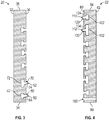
FIG. 4 is a partial cross-sectional view taken along section B-B. - A detailed description of one or more embodiments of the disclosed apparatus and method are presented herein by way of exemplification and not limitation with reference to the Figures.
- Referring to
FIGS. 1 and 2 , aduct assembly 10 having internal noise reduction features, thermal insulation, and leak detection features is shown. Theduct assembly 10 extends along and is disposed about anaxis 12. Theduct assembly 10 may have any appreciable shape while viewed in cross-section, such as ovate, rectangular, cylindrical, circular, or the like. Theduct assembly 10 includes afirst duct 20, asecond duct 22, and asupport member 24. - The
first duct 20 includes a firstinner wall 30 and a firstouter wall 32 that each extend between a first ductfirst end 34 and a first ductsecond end 36 along theaxis 12. The firstinner wall 30 defines an inner cavity or a first flow path 40 that is arranged to receive a fluid. For example, should theduct assembly 10 be incorporated into an environmental control system or bleed system, the first flow path 40 receives bleed air and directs the bleed air to another component of the environment control system or bleed system or directs the bleed air towards or within an aircraft cabin. - Referring to
FIGS. 1 and3 , thefirst duct 20 defines a plurality of resonators that are defined between the firstinner wall 30 and the firstouter wall 32. The plurality of resonators are built into thefirst duct 20 and have various sizes, shapes, or volumes that are tuned to the frequency range to damp flow resonated acoustic noise at specific frequencies. The resonators may be configured as Helmholtz resonators that are additively manufactured into thefirst duct 20. - Referring to
FIG. 3 , thefirst duct 20 defines a first ductfirst resonator 50 and a first ductsecond resonator 52. - The first duct
first resonator 50 extends between and is completely defined between the firstinner wall 30 and the firstouter wall 32. The first ductfirst resonator 50 includes afirst opening 60, afirst cavity 62, and afirst throat 64. Thefirst opening 60 extends through the firstinner wall 30. Thefirst cavity 62 is defined between and is spaced apart from each of the firstinner wall 30 and the firstouter wall 32. Thefirst cavity 62 has a first volume or a first resonator volume. Thefirst throat 64 extends between thefirst opening 60 and thefirst cavity 62 along an axis that is disposed substantially transverse to theaxis 12. Thefirst throat 64 has a first throat length. - The
first cavity 62 and thefirst throat 64 are sized to provide a spring effect or damping effect to damp or attenuate a particular frequency. The size or volume of thefirst cavity 62 and/or the first throat length of thefirst throat 64 are based on many factors, such as the density, temperature, or velocity of the fluid that flows through thefirst duct 20 and/or the diameter of thefirst duct 20. - The first duct
second resonator 52 is axially spaced apart from the first ductfirst resonator 50 along theaxis 12. The first ductsecond resonator 52 includes asecond opening 70, asecond cavity 72, and asecond throat 74. Thesecond opening 70 extends through the firstinner wall 30. Thesecond cavity 72 is defined between and is spaced apart from each of the firstinner wall 30 and the firstouter wall 32. Thesecond cavity 72 may be radially offset, relative to theaxis 12, from thefirst cavity 62. Thesecond cavity 72 has a second volume or a second resonator volume. Thesecond throat 74 extends between thesecond opening 70 and thesecond cavity 72 along an axis that is disposed substantially transverse to theaxis 12. Thesecond throat 74 has a second throat length. - The
second cavity 72 and thesecond throat 74 are sized to provide an acoustic or damping effect to damp or attenuate a particular acoustic frequency that may be different from the particular acoustic frequency that thefirst throat 64 and thefirst cavity 62 are to damp. The size or volume of thesecond cavity 72 and/or the second throat length of thesecond throat 74 based on many factors, such as the density, temperature, or velocity of the fluid that flows through thefirst duct 20 and/or the diameter of thefirst duct 20. - The first volume of the
first cavity 62 may be different from the second volume of thesecond cavity 72. In at least one embodiment, the first volume of thefirst cavity 62 may be less than the second volume of thesecond cavity 72. In other embodiments, the first volume of thefirst cavity 62 may be greater than or substantially equal to the second volume of thesecond cavity 72. - The first throat length of the
first throat 64 may be different from the second throat length of thesecond throat 74. In at least one embodiment, the first throat length of thefirst throat 64 may be less than the second throat length of thesecond throat 74. In other embodiments, the first throat length of thefirst throat 64 may be greater than or substantially equal to the second throat length of thesecond throat 74. - Additional first duct resonators may be defined between the first
inner wall 30 and the firstouter wall 32. The additional first duct resonators may be axially and/or radially spaced apart from the first ductfirst resonator 50 and the first ductsecond resonator 52. The size and shape of the additional first duct resonators may be different from the size and shape of the first ductfirst resonator 50 and the first ductsecond resonator 52. - Referring to
FIGS. 1 and4 , thesecond duct 22 is disposed about and is spaced apart from thefirst duct 20. Thesecond duct 22 includes a secondinner wall 80 and a secondouter wall 82 that each extend between a second ductfirst end 84 and a second ductsecond end 86 along theaxis 12. The secondinner wall 80 is spaced apart from the firstouter wall 32 such that an insulatingair gap 90 is defined between thefirst duct 20 and thesecond duct 22. - The insulating
air gap 90 acts as thermal insulation between thefirst duct 20 and thesecond duct 22. The size of insulatingair gap 90 may be based on a height, length, or width of thesupport member 24 that extends between thefirst duct 20 and thesecond duct 22. The insulatingair gap 90 is an insulating layer that is designed to accommodate a second outer wall touch temperature requirement. - The
second duct 22 defines aport 100. Theport 100 extends from the secondinner wall 80 to the secondouter wall 82. Theport 100 is fluidly connected to the insulatingair gap 90 such that a flow path may be created between a leak from thefirst duct 20 and theport 100. - A leakage detection sensor or
leakage detection system 102 is operatively connected to theport 100. Theleakage detection system 102 includes a sensing element that may detect leakage from within thefirst duct 20 that may bleed into the insulatingair gap 90 by detecting a change in flow within the insulatingair gap 90, a change in pressure within the insulatingair gap 90, or a change in temperature within the insulatingair gap 90. Theleakage detection system 102 is configured to output for display an indicator or warning indicative of leakage of fluid from within thefirst duct 20 responsive to the presence of fluid from within thefirst duct 20 being detected within the insulatingair gap 90 by a sensor of theleakage detection system 102. - Referring to
FIGS. 1 and4 , thesecond duct 22 defines a plurality of resonators that are defined between the secondinner wall 80 and the secondouter wall 82. The plurality of resonators are built into thesecond duct 22 and have various sizes, shapes, or volumes that are tuned to the specific frequency range to damp flow resonated acoustic noise at specific frequencies. The resonators may be configured as Helmholtz resonators that are additively manufactured into thesecond duct 22. - The
second duct 22 defines a second ductfirst resonator 110 and a second ductsecond resonator 112. In at least one embodiment, the second ductfirst resonator 110 may be out of phase with the first ductfirst resonator 50 such that the second ductfirst resonator 110 is axially offset from the first ductfirst resonator 50 along theaxis 12. In other embodiments, the second ductfirst resonator 110 may be in phase with the first ductfirst resonator 50 such that the second ductfirst resonator 110 is axially and radially aligned with the first ductfirst resonator 50. - The second duct
first resonator 110 extends between and is completely defined between the secondinner wall 80 and the secondouter wall 82. The second ductfirst resonator 110 includes a second duct first opening 120, a second ductfirst cavity 122, and a second duct first throat or a second ductfirst throat 124. The second duct first opening 120 extends through the secondinner wall 80. The second ductfirst cavity 122 is defined between and is spaced apart from each of the secondinner wall 80 and the secondouter wall 82. The second ductfirst cavity 122 has a first resonator volume. The second duct first throat 128 extends between the second duct first opening 120 and the second ductfirst cavity 122 along an axis that is disposed substantially transverse to theaxis 12. The second ductfirst throat 124 has a first throat length. - The second duct
first cavity 122 and the second ductfirst throat 124 are sized to provide an acoustic or damping effect to damp or attenuate a particular acoustic frequency. The size or volume of the second ductfirst cavity 122 and/or the first throat length of the second ductfirst throat 124 are based on many factors, such as the density, temperature, or velocity of the fluid that flows through thefirst duct 20 and/or the diameter of thefirst duct 20 orsecond duct 22. - The second duct
second resonator 112 is axially spaced apart from the second ductfirst resonator 110 along theaxis 12. The second ductsecond resonator 112 includes a second ductsecond opening 130, a second ductsecond cavity 132, and a second duct second throat or a second ductsecond throat 134. The second ductsecond opening 130 extends through the secondinner wall 80. The second ductsecond cavity 132 is defined between and is spaced apart from each of the secondinner wall 80 and the secondouter wall 82. The second ductsecond cavity 132 may be radially offset, relative to theaxis 12, from the second ductfirst cavity 122. The second ductsecond cavity 132 has a second resonator volume. The second ductsecond throat 134 extends between the second ductsecond opening 130 and the second ductsecond cavity 132 along an axis that is disposed substantially transverse to theaxis 12. The second ductsecond throat 134 has a second throat length. - The second duct
second cavity 132 and the second ductsecond throat 134 are sized to provide a spring effect or damping effect to damp a particular frequency that may be different from the particular frequency that the second ductfirst throat 124 and the second ductfirst cavity 122 are to damp. The size or volume of the second ductsecond cavity 132 and/or the second throat length of the second ductsecond throat 134 based on many factors, such as the density, temperature, or velocity of the fluid that flows through thefirst duct 20 and/or the diameter of thefirst duct 20 or thesecond duct 22. - The first resonator volume of the second duct
first cavity 122 may be different from the second resonator volume of the second ductsecond cavity 132. In at least one embodiment, the first resonator volume of the second ductfirst cavity 122 may be less than the second resonator volume of the second ductsecond cavity 132. In other embodiments, the first resonator volume of the second ductfirst cavity 122 may be greater than or substantially equal to the second resonator volume of the second ductsecond cavity 132. - The first throat length of the second duct
first throat 124 may be different from the second throat length of the second ductsecond throat 134. In at least one embodiment, the first throat length of the second ductfirst throat 124 may be less than the second throat length of the second ductsecond throat 134. In other embodiments, the first throat length of the second ductfirst throat 124 may be greater than or substantially equal to the second throat length of the second ductsecond throat 134. - Additional second duct resonators may be defined between the second
inner wall 80 and the secondouter wall 82. The additional second duct resonators may be axially and/or radially spaced apart from the second ductfirst resonator 110 and the second ductsecond resonator 112. The size and shape of the additional second duct resonators may be different from the size and shape of the second ductfirst resonator 110 and the second ductsecond resonator 112. - The
support member 24 extends between the firstouter wall 32 of thefirst duct 20 and the secondinner wall 80 of thesecond duct 22. In at least one embodiment, a plurality of circumferentially spaced apart support members extend between and are operatively connect thefirst duct 20 and thesecond duct 22. - The
support member 24 spaces thefirst duct 20 from thesecond duct 22. Thesupport member 24 may be additively manufactured along with thefirst duct 20 and thesecond duct 22 such that theduct assembly 10 is a single integrated unit that provides noise reduction features, insulation, and leak detection features. - The term "about" is intended to include the degree of error associated with measurement of the particular quantity based upon the equipment available at the time of filing the application.
- The terminology used herein is for the purpose of describing particular embodiments only and is not intended to be limiting of the present disclosure. As used herein, the singular forms "a", "an" and "the" are intended to include the plural forms as well, unless the context clearly indicates otherwise. It will be further understood that the terms "comprises" and/or "comprising," when used in this specification, specify the presence of stated features, integers, steps, operations, elements, and/or components, but do not preclude the presence or addition of one or more other features, integers, steps, operations, element components, and/or groups thereof.
- While the present disclosure has been described with reference to an exemplary embodiment or embodiments, it will be understood by those skilled in the art that various changes may be made and equivalents may be substituted for elements thereof without departing from the scope of the present disclosure. In addition, many modifications may be made to adapt a particular situation or material to the teachings of the present disclosure without departing from the essential scope thereof. Therefore, it is intended that the present disclosure not be limited to the particular embodiment disclosed as the best mode contemplated for carrying out this present disclosure, but that the present disclosure will include all embodiments falling within the scope of the claims.
Claims (11)
- A duct assembly (10), comprising:a first duct (20) having a first inner wall (30) and a first outer wall (32), each extending between a first duct first end (34) and a first duct second end (36), the first duct (20) defining a first duct first resonator (50) that extends between the first inner wall (30) and the first outer wall (32), the first inner wall (30) defining a first flow path.
- The duct assembly of claim 1, wherein the first duct first resonator (50) includes a first opening that extends through the first inner wall (30), a first cavity (62) defined between the first inner wall (30) and the first outer wall (32), and a first throat (64) extending between the first opening and the first cavity.
- The duct assembly of claim 2, wherein the first duct (20) defines a first duct second resonator (52) that is spaced apart from the first duct first resonator (50).
- The duct assembly of claim 3, wherein the first duct second resonator (52) defines a second opening (70) that extends through the first inner wall (30), a second cavity (72) that is defined between the first inner wall (30) and the first outer wall (32), and a second throat (74) that extends between the second opening (70) and the second cavity (32).
- The duct assembly of claim 4, wherein the first cavity (62) has a first volume and the second cavity (72) has a second volume.
- The duct assembly of claim 5, wherein the first volume is different from the second volume.
- The duct assembly of claim 2, further comprising:a second duct (22) that is disposed about the first duct (20), the second duct (22) having a second inner wall (80) spaced apart from the first outer wall (32) and a second outer wall (82), each extending between a second duct first end (84) and a second duct second end (86).
- The duct assembly of claim 7, wherein the second duct (22) defines a port (100) that extends from the second inner wall (80) to the second outer wall (82).
- The duct assembly of claim 7, further comprising:a support member (24) that extends between the first outer wall (32)) and the second inner wall (80), spacing the second duct (22) apart from the first duct (22).
- The duct assembly of claim 9, wherein an insulating air gap is defined between the first outer wall (32) of the first duct (20) and the second inner wall (82) of the second duct (22).
- The duct assembly of claim 7, wherein the second duct (22) defines a second duct first resonator (110) that is defined between the second inner wall (80) and the second outer wall (82).
Applications Claiming Priority (1)
| Application Number | Priority Date | Filing Date | Title |
|---|---|---|---|
| US15/790,786 US20190120414A1 (en) | 2017-10-23 | 2017-10-23 | Duct assembly having internal noise reduction features, thermal insulation and leak detection |
Publications (2)
| Publication Number | Publication Date |
|---|---|
| EP3473910A1 true EP3473910A1 (en) | 2019-04-24 |
| EP3473910B1 EP3473910B1 (en) | 2022-04-20 |
Family
ID=63965354
Family Applications (1)
| Application Number | Title | Priority Date | Filing Date |
|---|---|---|---|
| EP18201988.5A Active EP3473910B1 (en) | 2017-10-23 | 2018-10-23 | Duct assembly having internal noise reduction features, thermal insulation and leak detection |
Country Status (2)
| Country | Link |
|---|---|
| US (1) | US20190120414A1 (en) |
| EP (1) | EP3473910B1 (en) |
Cited By (1)
| Publication number | Priority date | Publication date | Assignee | Title |
|---|---|---|---|---|
| US20210207752A1 (en) * | 2020-01-02 | 2021-07-08 | The Boeing Company | Enhanced fluid deflection angle structures and methods for manufacturing |
Families Citing this family (2)
| Publication number | Priority date | Publication date | Assignee | Title |
|---|---|---|---|---|
| US12358627B2 (en) | 2022-10-21 | 2025-07-15 | The Boeing Company | Acoustic air duct for environmental control system in vehicle |
| EP4635849A1 (en) * | 2024-04-15 | 2025-10-22 | Goodrich Lighting Systems GmbH & Co. KG | Aircraft passenger service unit, aircraft comprising the same, and method for controlling an aircraft passenger service unit |
Citations (6)
| Publication number | Priority date | Publication date | Assignee | Title |
|---|---|---|---|---|
| GB1574480A (en) * | 1977-12-14 | 1980-09-10 | Eurovib Acoustic Products | Sound absorbing device |
| DE4232195C1 (en) * | 1992-09-25 | 1993-06-24 | Man Nutzfahrzeuge Ag, 8000 Muenchen, De | |
| EP1291570A2 (en) * | 2001-09-07 | 2003-03-12 | Avon Polymer Products Limited | Noise and vibration suppressors |
| US20100187038A1 (en) * | 2009-01-23 | 2010-07-29 | Dresser-Rand Company | Fluid-carrying conduit and method with noise attenuation |
| EP2952747A1 (en) * | 2014-06-02 | 2015-12-09 | Ingersoll-Rand Company | Compressor system with resonator |
| EP3086011A1 (en) * | 2015-04-21 | 2016-10-26 | Airbus Operations GmbH | Double-walled pipe with integrated heating capability for an aircraft or spacecraft |
Family Cites Families (29)
| Publication number | Priority date | Publication date | Assignee | Title |
|---|---|---|---|---|
| US2297046A (en) * | 1939-08-25 | 1942-09-29 | Maxim Silencer Co | Means for preventing shock excitation of acoustic conduits or chambers |
| US2810449A (en) * | 1955-04-12 | 1957-10-22 | North American Aviation Inc | Sound abatement device for jet engines |
| US3439774A (en) * | 1966-01-21 | 1969-04-22 | Boeing Co | Sound energy absorbing apparatus |
| GB1242864A (en) * | 1968-05-15 | 1971-08-18 | Dunlop Holdings Ltd | Acoustical elements |
| DE2131410C3 (en) * | 1971-06-24 | 1975-04-30 | Costa Silard Dipl.-Ing. Dr. 7400 Tuebingen Vasiljevic | Silencers, in particular for ventilation systems |
| US3920095A (en) * | 1974-02-01 | 1975-11-18 | Brunswick Corp | Free flow sound attenuating device and method of using |
| US4014369A (en) * | 1975-12-31 | 1977-03-29 | Exxon Research And Engineering Company | Triple pipe low temperature pipeline |
| US4615359A (en) * | 1982-08-30 | 1986-10-07 | Affa Stephen N | Shroud for aircraft duct |
| NL8602537A (en) * | 1986-10-09 | 1988-05-02 | Zwaan Adrianus J | SOUNDPROOFING VENTILATION DEVICE, IN PARTICULAR FOR A VENTILATION TRANSIT IN A WALL OR WALL. |
| US4786088A (en) * | 1987-06-25 | 1988-11-22 | Asahi/America, Inc. | Double-containment thermoplastic pipe assembly |
| US5048572A (en) * | 1987-10-15 | 1991-09-17 | Essex Group, Inc. | Vibration damping heat shrinkable tubing |
| US5497809A (en) * | 1994-01-05 | 1996-03-12 | Wolf; Lawrence W. | Vented bending sleeves for coaxial tubing systems |
| JPH0868490A (en) * | 1994-08-26 | 1996-03-12 | Excel Kk | Hollow molded body having silencer section |
| US6056019A (en) * | 1998-09-08 | 2000-05-02 | The United States Of America As Represented By The Secretary Of The Navy | Apparatus for acoustically isolating a high pressure steam pipe in a flooded structure |
| JP3683427B2 (en) * | 1999-02-04 | 2005-08-17 | 東海ゴム工業株式会社 | Soundproof material |
| GB9917733D0 (en) * | 1999-07-28 | 1999-09-29 | Kvaerner Earl & Wright | Thermal insulated pipelines |
| DE10112010B4 (en) * | 2001-03-13 | 2018-03-08 | Valeo Klimasysteme Gmbh | Air duct and motor vehicle heating, ventilation and air conditioning |
| EP1404501B1 (en) * | 2001-06-05 | 2012-08-01 | Mikro Systems Inc. | Method and mold system for manufacturing three-dimensional devices |
| US6799657B2 (en) * | 2002-10-02 | 2004-10-05 | Carrier Corporation | Absorptive/reactive muffler for variable speed compressors |
| KR20060008972A (en) * | 2003-05-02 | 2006-01-27 | 오웬스 코닝 | Muffler with improved acoustic performance at low and proper frequency |
| WO2007120642A2 (en) * | 2006-04-11 | 2007-10-25 | Daikin Industries, Ltd. | Dual-containment pipe containing fluoropolymer |
| EP2534343B1 (en) * | 2010-02-11 | 2017-03-15 | Faurecia Emissions Control Technologies, USA, LLC | Plastic muffler with helmholtz chamber |
| KR101211301B1 (en) * | 2011-01-13 | 2012-12-11 | 엘에스엠트론 주식회사 | resonator |
| WO2013152793A1 (en) * | 2012-04-12 | 2013-10-17 | Siemens Aktiengesellschaft | Reflection silencer |
| EP2900948B1 (en) * | 2012-09-27 | 2018-03-07 | Eaton Corporation | Integral resonators for roots-type supercharger |
| US9470343B2 (en) * | 2014-05-21 | 2016-10-18 | Motan Holding Gmbh | Pipe for a conveying line for conveying bulk material as well as device for leakage monitoring of a conveying line |
| EP3192068A1 (en) * | 2014-09-09 | 2017-07-19 | 3M Innovative Properties Company | Acoustic device |
| DE202014009602U1 (en) * | 2014-12-03 | 2016-03-04 | GM Global Technology Operations LLC (n. d. Ges. d. Staates Delaware) | Silencer for an internal combustion engine of a motor vehicle |
| US9376946B1 (en) * | 2015-04-02 | 2016-06-28 | Fisher Controls International Llc | Modal attenuator |
-
2017
- 2017-10-23 US US15/790,786 patent/US20190120414A1/en not_active Abandoned
-
2018
- 2018-10-23 EP EP18201988.5A patent/EP3473910B1/en active Active
Patent Citations (6)
| Publication number | Priority date | Publication date | Assignee | Title |
|---|---|---|---|---|
| GB1574480A (en) * | 1977-12-14 | 1980-09-10 | Eurovib Acoustic Products | Sound absorbing device |
| DE4232195C1 (en) * | 1992-09-25 | 1993-06-24 | Man Nutzfahrzeuge Ag, 8000 Muenchen, De | |
| EP1291570A2 (en) * | 2001-09-07 | 2003-03-12 | Avon Polymer Products Limited | Noise and vibration suppressors |
| US20100187038A1 (en) * | 2009-01-23 | 2010-07-29 | Dresser-Rand Company | Fluid-carrying conduit and method with noise attenuation |
| EP2952747A1 (en) * | 2014-06-02 | 2015-12-09 | Ingersoll-Rand Company | Compressor system with resonator |
| EP3086011A1 (en) * | 2015-04-21 | 2016-10-26 | Airbus Operations GmbH | Double-walled pipe with integrated heating capability for an aircraft or spacecraft |
Cited By (2)
| Publication number | Priority date | Publication date | Assignee | Title |
|---|---|---|---|---|
| US20210207752A1 (en) * | 2020-01-02 | 2021-07-08 | The Boeing Company | Enhanced fluid deflection angle structures and methods for manufacturing |
| US11549629B2 (en) * | 2020-01-02 | 2023-01-10 | The Boeing Company | Enhanced fluid deflection angle structures and methods for manufacturing |
Also Published As
| Publication number | Publication date |
|---|---|
| EP3473910B1 (en) | 2022-04-20 |
| US20190120414A1 (en) | 2019-04-25 |
Similar Documents
| Publication | Publication Date | Title |
|---|---|---|
| EP3473910B1 (en) | Duct assembly having internal noise reduction features, thermal insulation and leak detection | |
| CN108700495B (en) | Leak detection method for open type emission analysis and open type emission analysis device | |
| EP3106881B1 (en) | Pitot tube moisture removal enhancement | |
| EP4219987B1 (en) | Metering valve for a fuel metering unit | |
| US9926841B2 (en) | Acoustic measuring device | |
| US10808874B2 (en) | Inline fluid damper device | |
| CN110506198A (en) | Device for measuring ultrasonic wave flow | |
| KR20120044629A (en) | Noise reduction apparatus capable of compensating temperature | |
| CN105806550B (en) | Pneumatic filter | |
| KR101816020B1 (en) | Variable RPM type fan noise reducing device | |
| EP3540399B1 (en) | Asymmetric piezometer ring | |
| JP2021517645A (en) | Sensor configuration | |
| CN104061393B (en) | Test threeway for pressure transducer | |
| WO2016051197A1 (en) | Measurement system and methods | |
| EP3330690B1 (en) | Monitoring system and method for a multiple-walled fluid system | |
| WO2023027616A1 (en) | Acoustic spectroscopy assembly and a method for determining a property of a fluid in a pipe using the acoustic spectroscopy assembly | |
| EP3354575B1 (en) | Flow sensing ozone converter | |
| US10513945B2 (en) | Instrumented flow passage of a turbine engine | |
| Schroeder et al. | A New Test Rig for Time-Resolved Pressure Measurements in Rotating Cavities With Pulsed Inflow | |
| WO2016075048A1 (en) | Device for dampening pressure pulsations in a gas flow | |
| FI84758C (en) | FOERFARANDE FOER MAETNING AV LUFTSTROEM OCH LUFTSPRIDARE DAER FOERFARANDET HAR TILLAEMPATS. | |
| CN107438760A (en) | Improved vibrating member for vibrating densitometer | |
| HK1210830A1 (en) | Differential pressure flow meter with angled pressure ports | |
| HK1210830B (en) | Differential pressure flow meter with angled pressure ports | |
| KR20140003073A (en) | Measurement system and method variable valve |
Legal Events
| Date | Code | Title | Description |
|---|---|---|---|
| PUAI | Public reference made under article 153(3) epc to a published international application that has entered the european phase |
Free format text: ORIGINAL CODE: 0009012 |
|
| STAA | Information on the status of an ep patent application or granted ep patent |
Free format text: STATUS: THE APPLICATION HAS BEEN PUBLISHED |
|
| AK | Designated contracting states |
Kind code of ref document: A1 Designated state(s): AL AT BE BG CH CY CZ DE DK EE ES FI FR GB GR HR HU IE IS IT LI LT LU LV MC MK MT NL NO PL PT RO RS SE SI SK SM TR |
|
| AX | Request for extension of the european patent |
Extension state: BA ME |
|
| STAA | Information on the status of an ep patent application or granted ep patent |
Free format text: STATUS: REQUEST FOR EXAMINATION WAS MADE |
|
| 17P | Request for examination filed |
Effective date: 20191024 |
|
| RBV | Designated contracting states (corrected) |
Designated state(s): AL AT BE BG CH CY CZ DE DK EE ES FI FR GB GR HR HU IE IS IT LI LT LU LV MC MK MT NL NO PL PT RO RS SE SI SK SM TR |
|
| GRAP | Despatch of communication of intention to grant a patent |
Free format text: ORIGINAL CODE: EPIDOSNIGR1 |
|
| STAA | Information on the status of an ep patent application or granted ep patent |
Free format text: STATUS: GRANT OF PATENT IS INTENDED |
|
| RIC1 | Information provided on ipc code assigned before grant |
Ipc: F16L 55/027 20060101ALN20211026BHEP Ipc: B64D 13/00 20060101ALI20211026BHEP Ipc: B29C 64/00 20170101ALI20211026BHEP Ipc: B33Y 80/00 20150101ALI20211026BHEP Ipc: F16L 55/033 20060101ALI20211026BHEP Ipc: F16L 9/18 20060101AFI20211026BHEP |
|
| INTG | Intention to grant announced |
Effective date: 20211118 |
|
| GRAS | Grant fee paid |
Free format text: ORIGINAL CODE: EPIDOSNIGR3 |
|
| GRAA | (expected) grant |
Free format text: ORIGINAL CODE: 0009210 |
|
| STAA | Information on the status of an ep patent application or granted ep patent |
Free format text: STATUS: THE PATENT HAS BEEN GRANTED |
|
| AK | Designated contracting states |
Kind code of ref document: B1 Designated state(s): AL AT BE BG CH CY CZ DE DK EE ES FI FR GB GR HR HU IE IS IT LI LT LU LV MC MK MT NL NO PL PT RO RS SE SI SK SM TR |
|
| REG | Reference to a national code |
Ref country code: GB Ref legal event code: FG4D |
|
| REG | Reference to a national code |
Ref country code: CH Ref legal event code: EP |
|
| REG | Reference to a national code |
Ref country code: DE Ref legal event code: R096 Ref document number: 602018034069 Country of ref document: DE |
|
| REG | Reference to a national code |
Ref country code: IE Ref legal event code: FG4D |
|
| REG | Reference to a national code |
Ref country code: AT Ref legal event code: REF Ref document number: 1485391 Country of ref document: AT Kind code of ref document: T Effective date: 20220515 |
|
| REG | Reference to a national code |
Ref country code: LT Ref legal event code: MG9D |
|
| REG | Reference to a national code |
Ref country code: NL Ref legal event code: MP Effective date: 20220420 |
|
| REG | Reference to a national code |
Ref country code: AT Ref legal event code: MK05 Ref document number: 1485391 Country of ref document: AT Kind code of ref document: T Effective date: 20220420 |
|
| PG25 | Lapsed in a contracting state [announced via postgrant information from national office to epo] |
Ref country code: NL Free format text: LAPSE BECAUSE OF FAILURE TO SUBMIT A TRANSLATION OF THE DESCRIPTION OR TO PAY THE FEE WITHIN THE PRESCRIBED TIME-LIMIT Effective date: 20220420 |
|
| PG25 | Lapsed in a contracting state [announced via postgrant information from national office to epo] |
Ref country code: SE Free format text: LAPSE BECAUSE OF FAILURE TO SUBMIT A TRANSLATION OF THE DESCRIPTION OR TO PAY THE FEE WITHIN THE PRESCRIBED TIME-LIMIT Effective date: 20220420 Ref country code: PT Free format text: LAPSE BECAUSE OF FAILURE TO SUBMIT A TRANSLATION OF THE DESCRIPTION OR TO PAY THE FEE WITHIN THE PRESCRIBED TIME-LIMIT Effective date: 20220822 Ref country code: NO Free format text: LAPSE BECAUSE OF FAILURE TO SUBMIT A TRANSLATION OF THE DESCRIPTION OR TO PAY THE FEE WITHIN THE PRESCRIBED TIME-LIMIT Effective date: 20220720 Ref country code: LT Free format text: LAPSE BECAUSE OF FAILURE TO SUBMIT A TRANSLATION OF THE DESCRIPTION OR TO PAY THE FEE WITHIN THE PRESCRIBED TIME-LIMIT Effective date: 20220420 Ref country code: HR Free format text: LAPSE BECAUSE OF FAILURE TO SUBMIT A TRANSLATION OF THE DESCRIPTION OR TO PAY THE FEE WITHIN THE PRESCRIBED TIME-LIMIT Effective date: 20220420 Ref country code: GR Free format text: LAPSE BECAUSE OF FAILURE TO SUBMIT A TRANSLATION OF THE DESCRIPTION OR TO PAY THE FEE WITHIN THE PRESCRIBED TIME-LIMIT Effective date: 20220721 Ref country code: FI Free format text: LAPSE BECAUSE OF FAILURE TO SUBMIT A TRANSLATION OF THE DESCRIPTION OR TO PAY THE FEE WITHIN THE PRESCRIBED TIME-LIMIT Effective date: 20220420 Ref country code: ES Free format text: LAPSE BECAUSE OF FAILURE TO SUBMIT A TRANSLATION OF THE DESCRIPTION OR TO PAY THE FEE WITHIN THE PRESCRIBED TIME-LIMIT Effective date: 20220420 Ref country code: BG Free format text: LAPSE BECAUSE OF FAILURE TO SUBMIT A TRANSLATION OF THE DESCRIPTION OR TO PAY THE FEE WITHIN THE PRESCRIBED TIME-LIMIT Effective date: 20220720 Ref country code: AT Free format text: LAPSE BECAUSE OF FAILURE TO SUBMIT A TRANSLATION OF THE DESCRIPTION OR TO PAY THE FEE WITHIN THE PRESCRIBED TIME-LIMIT Effective date: 20220420 |
|
| PG25 | Lapsed in a contracting state [announced via postgrant information from national office to epo] |
Ref country code: RS Free format text: LAPSE BECAUSE OF FAILURE TO SUBMIT A TRANSLATION OF THE DESCRIPTION OR TO PAY THE FEE WITHIN THE PRESCRIBED TIME-LIMIT Effective date: 20220420 Ref country code: PL Free format text: LAPSE BECAUSE OF FAILURE TO SUBMIT A TRANSLATION OF THE DESCRIPTION OR TO PAY THE FEE WITHIN THE PRESCRIBED TIME-LIMIT Effective date: 20220420 Ref country code: LV Free format text: LAPSE BECAUSE OF FAILURE TO SUBMIT A TRANSLATION OF THE DESCRIPTION OR TO PAY THE FEE WITHIN THE PRESCRIBED TIME-LIMIT Effective date: 20220420 Ref country code: IS Free format text: LAPSE BECAUSE OF FAILURE TO SUBMIT A TRANSLATION OF THE DESCRIPTION OR TO PAY THE FEE WITHIN THE PRESCRIBED TIME-LIMIT Effective date: 20220820 |
|
| REG | Reference to a national code |
Ref country code: DE Ref legal event code: R097 Ref document number: 602018034069 Country of ref document: DE |
|
| PG25 | Lapsed in a contracting state [announced via postgrant information from national office to epo] |
Ref country code: SM Free format text: LAPSE BECAUSE OF FAILURE TO SUBMIT A TRANSLATION OF THE DESCRIPTION OR TO PAY THE FEE WITHIN THE PRESCRIBED TIME-LIMIT Effective date: 20220420 Ref country code: SK Free format text: LAPSE BECAUSE OF FAILURE TO SUBMIT A TRANSLATION OF THE DESCRIPTION OR TO PAY THE FEE WITHIN THE PRESCRIBED TIME-LIMIT Effective date: 20220420 Ref country code: RO Free format text: LAPSE BECAUSE OF FAILURE TO SUBMIT A TRANSLATION OF THE DESCRIPTION OR TO PAY THE FEE WITHIN THE PRESCRIBED TIME-LIMIT Effective date: 20220420 Ref country code: EE Free format text: LAPSE BECAUSE OF FAILURE TO SUBMIT A TRANSLATION OF THE DESCRIPTION OR TO PAY THE FEE WITHIN THE PRESCRIBED TIME-LIMIT Effective date: 20220420 Ref country code: DK Free format text: LAPSE BECAUSE OF FAILURE TO SUBMIT A TRANSLATION OF THE DESCRIPTION OR TO PAY THE FEE WITHIN THE PRESCRIBED TIME-LIMIT Effective date: 20220420 Ref country code: CZ Free format text: LAPSE BECAUSE OF FAILURE TO SUBMIT A TRANSLATION OF THE DESCRIPTION OR TO PAY THE FEE WITHIN THE PRESCRIBED TIME-LIMIT Effective date: 20220420 |
|
| PLBE | No opposition filed within time limit |
Free format text: ORIGINAL CODE: 0009261 |
|
| STAA | Information on the status of an ep patent application or granted ep patent |
Free format text: STATUS: NO OPPOSITION FILED WITHIN TIME LIMIT |
|
| 26N | No opposition filed |
Effective date: 20230123 |
|
| PG25 | Lapsed in a contracting state [announced via postgrant information from national office to epo] |
Ref country code: AL Free format text: LAPSE BECAUSE OF FAILURE TO SUBMIT A TRANSLATION OF THE DESCRIPTION OR TO PAY THE FEE WITHIN THE PRESCRIBED TIME-LIMIT Effective date: 20220420 |
|
| PG25 | Lapsed in a contracting state [announced via postgrant information from national office to epo] |
Ref country code: SI Free format text: LAPSE BECAUSE OF FAILURE TO SUBMIT A TRANSLATION OF THE DESCRIPTION OR TO PAY THE FEE WITHIN THE PRESCRIBED TIME-LIMIT Effective date: 20220420 Ref country code: MC Free format text: LAPSE BECAUSE OF FAILURE TO SUBMIT A TRANSLATION OF THE DESCRIPTION OR TO PAY THE FEE WITHIN THE PRESCRIBED TIME-LIMIT Effective date: 20220420 |
|
| REG | Reference to a national code |
Ref country code: CH Ref legal event code: PL |
|
| REG | Reference to a national code |
Ref country code: BE Ref legal event code: MM Effective date: 20221031 |
|
| P01 | Opt-out of the competence of the unified patent court (upc) registered |
Effective date: 20230522 |
|
| PG25 | Lapsed in a contracting state [announced via postgrant information from national office to epo] |
Ref country code: LU Free format text: LAPSE BECAUSE OF NON-PAYMENT OF DUE FEES Effective date: 20221023 |
|
| PG25 | Lapsed in a contracting state [announced via postgrant information from national office to epo] |
Ref country code: LI Free format text: LAPSE BECAUSE OF NON-PAYMENT OF DUE FEES Effective date: 20221031 Ref country code: CH Free format text: LAPSE BECAUSE OF NON-PAYMENT OF DUE FEES Effective date: 20221031 |
|
| PG25 | Lapsed in a contracting state [announced via postgrant information from national office to epo] |
Ref country code: BE Free format text: LAPSE BECAUSE OF NON-PAYMENT OF DUE FEES Effective date: 20221031 |
|
| PG25 | Lapsed in a contracting state [announced via postgrant information from national office to epo] |
Ref country code: IE Free format text: LAPSE BECAUSE OF NON-PAYMENT OF DUE FEES Effective date: 20221023 |
|
| PG25 | Lapsed in a contracting state [announced via postgrant information from national office to epo] |
Ref country code: IT Free format text: LAPSE BECAUSE OF FAILURE TO SUBMIT A TRANSLATION OF THE DESCRIPTION OR TO PAY THE FEE WITHIN THE PRESCRIBED TIME-LIMIT Effective date: 20220420 |
|
| PG25 | Lapsed in a contracting state [announced via postgrant information from national office to epo] |
Ref country code: HU Free format text: LAPSE BECAUSE OF FAILURE TO SUBMIT A TRANSLATION OF THE DESCRIPTION OR TO PAY THE FEE WITHIN THE PRESCRIBED TIME-LIMIT; INVALID AB INITIO Effective date: 20181023 |
|
| PG25 | Lapsed in a contracting state [announced via postgrant information from national office to epo] |
Ref country code: CY Free format text: LAPSE BECAUSE OF FAILURE TO SUBMIT A TRANSLATION OF THE DESCRIPTION OR TO PAY THE FEE WITHIN THE PRESCRIBED TIME-LIMIT Effective date: 20220420 |
|
| PG25 | Lapsed in a contracting state [announced via postgrant information from national office to epo] |
Ref country code: MK Free format text: LAPSE BECAUSE OF FAILURE TO SUBMIT A TRANSLATION OF THE DESCRIPTION OR TO PAY THE FEE WITHIN THE PRESCRIBED TIME-LIMIT Effective date: 20220420 |
|
| PG25 | Lapsed in a contracting state [announced via postgrant information from national office to epo] |
Ref country code: MT Free format text: LAPSE BECAUSE OF FAILURE TO SUBMIT A TRANSLATION OF THE DESCRIPTION OR TO PAY THE FEE WITHIN THE PRESCRIBED TIME-LIMIT Effective date: 20220420 |
|
| PG25 | Lapsed in a contracting state [announced via postgrant information from national office to epo] |
Ref country code: BG Free format text: LAPSE BECAUSE OF FAILURE TO SUBMIT A TRANSLATION OF THE DESCRIPTION OR TO PAY THE FEE WITHIN THE PRESCRIBED TIME-LIMIT Effective date: 20220420 |
|
| PG25 | Lapsed in a contracting state [announced via postgrant information from national office to epo] |
Ref country code: BG Free format text: LAPSE BECAUSE OF FAILURE TO SUBMIT A TRANSLATION OF THE DESCRIPTION OR TO PAY THE FEE WITHIN THE PRESCRIBED TIME-LIMIT Effective date: 20220420 |
|
| PGFP | Annual fee paid to national office [announced via postgrant information from national office to epo] |
Ref country code: GB Payment date: 20250923 Year of fee payment: 8 |
|
| PGFP | Annual fee paid to national office [announced via postgrant information from national office to epo] |
Ref country code: FR Payment date: 20250924 Year of fee payment: 8 |
|
| PG25 | Lapsed in a contracting state [announced via postgrant information from national office to epo] |
Ref country code: TR Free format text: LAPSE BECAUSE OF FAILURE TO SUBMIT A TRANSLATION OF THE DESCRIPTION OR TO PAY THE FEE WITHIN THE PRESCRIBED TIME-LIMIT Effective date: 20220420 |
|
| PGFP | Annual fee paid to national office [announced via postgrant information from national office to epo] |
Ref country code: DE Payment date: 20250923 Year of fee payment: 8 |