EP3473896B1 - Seal plate located between two housing portions in an integrated drive generator - Google Patents
Seal plate located between two housing portions in an integrated drive generator Download PDFInfo
- Publication number
- EP3473896B1 EP3473896B1 EP18197716.6A EP18197716A EP3473896B1 EP 3473896 B1 EP3473896 B1 EP 3473896B1 EP 18197716 A EP18197716 A EP 18197716A EP 3473896 B1 EP3473896 B1 EP 3473896B1
- Authority
- EP
- European Patent Office
- Prior art keywords
- zone
- zones
- seal plate
- bolt hole
- oil passage
- Prior art date
- Legal status (The legal status is an assumption and is not a legal conclusion. Google has not performed a legal analysis and makes no representation as to the accuracy of the status listed.)
- Active
Links
Images

Classifications
-
- F—MECHANICAL ENGINEERING; LIGHTING; HEATING; WEAPONS; BLASTING
- F02—COMBUSTION ENGINES; HOT-GAS OR COMBUSTION-PRODUCT ENGINE PLANTS
- F02C—GAS-TURBINE PLANTS; AIR INTAKES FOR JET-PROPULSION PLANTS; CONTROLLING FUEL SUPPLY IN AIR-BREATHING JET-PROPULSION PLANTS
- F02C7/00—Features, components parts, details or accessories, not provided for in, or of interest apart form groups F02C1/00 - F02C6/00; Air intakes for jet-propulsion plants
- F02C7/32—Arrangement, mounting, or driving, of auxiliaries
-
- F—MECHANICAL ENGINEERING; LIGHTING; HEATING; WEAPONS; BLASTING
- F16—ENGINEERING ELEMENTS AND UNITS; GENERAL MEASURES FOR PRODUCING AND MAINTAINING EFFECTIVE FUNCTIONING OF MACHINES OR INSTALLATIONS; THERMAL INSULATION IN GENERAL
- F16J—PISTONS; CYLINDERS; SEALINGS
- F16J15/00—Sealings
- F16J15/02—Sealings between relatively-stationary surfaces
- F16J15/06—Sealings between relatively-stationary surfaces with solid packing compressed between sealing surfaces
- F16J15/061—Sealings between relatively-stationary surfaces with solid packing compressed between sealing surfaces with positioning means
-
- F—MECHANICAL ENGINEERING; LIGHTING; HEATING; WEAPONS; BLASTING
- F16—ENGINEERING ELEMENTS AND UNITS; GENERAL MEASURES FOR PRODUCING AND MAINTAINING EFFECTIVE FUNCTIONING OF MACHINES OR INSTALLATIONS; THERMAL INSULATION IN GENERAL
- F16J—PISTONS; CYLINDERS; SEALINGS
- F16J15/00—Sealings
- F16J15/02—Sealings between relatively-stationary surfaces
- F16J15/06—Sealings between relatively-stationary surfaces with solid packing compressed between sealing surfaces
- F16J15/08—Sealings between relatively-stationary surfaces with solid packing compressed between sealing surfaces with exclusively metal packing
- F16J15/0818—Flat gaskets
-
- F—MECHANICAL ENGINEERING; LIGHTING; HEATING; WEAPONS; BLASTING
- F16—ENGINEERING ELEMENTS AND UNITS; GENERAL MEASURES FOR PRODUCING AND MAINTAINING EFFECTIVE FUNCTIONING OF MACHINES OR INSTALLATIONS; THERMAL INSULATION IN GENERAL
- F16J—PISTONS; CYLINDERS; SEALINGS
- F16J15/00—Sealings
- F16J15/02—Sealings between relatively-stationary surfaces
- F16J15/06—Sealings between relatively-stationary surfaces with solid packing compressed between sealing surfaces
- F16J15/10—Sealings between relatively-stationary surfaces with solid packing compressed between sealing surfaces with non-metallic packing
- F16J15/104—Sealings between relatively-stationary surfaces with solid packing compressed between sealing surfaces with non-metallic packing characterised by structure
-
- F—MECHANICAL ENGINEERING; LIGHTING; HEATING; WEAPONS; BLASTING
- F16—ENGINEERING ELEMENTS AND UNITS; GENERAL MEASURES FOR PRODUCING AND MAINTAINING EFFECTIVE FUNCTIONING OF MACHINES OR INSTALLATIONS; THERMAL INSULATION IN GENERAL
- F16J—PISTONS; CYLINDERS; SEALINGS
- F16J15/00—Sealings
- F16J15/02—Sealings between relatively-stationary surfaces
- F16J15/06—Sealings between relatively-stationary surfaces with solid packing compressed between sealing surfaces
- F16J15/10—Sealings between relatively-stationary surfaces with solid packing compressed between sealing surfaces with non-metallic packing
- F16J15/12—Sealings between relatively-stationary surfaces with solid packing compressed between sealing surfaces with non-metallic packing with metal reinforcement or covering
- F16J15/121—Sealings between relatively-stationary surfaces with solid packing compressed between sealing surfaces with non-metallic packing with metal reinforcement or covering with metal reinforcement
- F16J15/122—Sealings between relatively-stationary surfaces with solid packing compressed between sealing surfaces with non-metallic packing with metal reinforcement or covering with metal reinforcement generally parallel to the surfaces
- F16J15/123—Details relating to the edges of the packing
-
- F—MECHANICAL ENGINEERING; LIGHTING; HEATING; WEAPONS; BLASTING
- F16—ENGINEERING ELEMENTS AND UNITS; GENERAL MEASURES FOR PRODUCING AND MAINTAINING EFFECTIVE FUNCTIONING OF MACHINES OR INSTALLATIONS; THERMAL INSULATION IN GENERAL
- F16J—PISTONS; CYLINDERS; SEALINGS
- F16J15/00—Sealings
- F16J15/02—Sealings between relatively-stationary surfaces
- F16J15/06—Sealings between relatively-stationary surfaces with solid packing compressed between sealing surfaces
- F16J15/10—Sealings between relatively-stationary surfaces with solid packing compressed between sealing surfaces with non-metallic packing
- F16J15/12—Sealings between relatively-stationary surfaces with solid packing compressed between sealing surfaces with non-metallic packing with metal reinforcement or covering
- F16J15/121—Sealings between relatively-stationary surfaces with solid packing compressed between sealing surfaces with non-metallic packing with metal reinforcement or covering with metal reinforcement
- F16J15/127—Sealings between relatively-stationary surfaces with solid packing compressed between sealing surfaces with non-metallic packing with metal reinforcement or covering with metal reinforcement the reinforcement being a compression stopper
-
- F—MECHANICAL ENGINEERING; LIGHTING; HEATING; WEAPONS; BLASTING
- F02—COMBUSTION ENGINES; HOT-GAS OR COMBUSTION-PRODUCT ENGINE PLANTS
- F02C—GAS-TURBINE PLANTS; AIR INTAKES FOR JET-PROPULSION PLANTS; CONTROLLING FUEL SUPPLY IN AIR-BREATHING JET-PROPULSION PLANTS
- F02C7/00—Features, components parts, details or accessories, not provided for in, or of interest apart form groups F02C1/00 - F02C6/00; Air intakes for jet-propulsion plants
- F02C7/28—Arrangement of seals
-
- F—MECHANICAL ENGINEERING; LIGHTING; HEATING; WEAPONS; BLASTING
- F16—ENGINEERING ELEMENTS AND UNITS; GENERAL MEASURES FOR PRODUCING AND MAINTAINING EFFECTIVE FUNCTIONING OF MACHINES OR INSTALLATIONS; THERMAL INSULATION IN GENERAL
- F16J—PISTONS; CYLINDERS; SEALINGS
- F16J15/00—Sealings
- F16J15/02—Sealings between relatively-stationary surfaces
- F16J15/06—Sealings between relatively-stationary surfaces with solid packing compressed between sealing surfaces
- F16J15/08—Sealings between relatively-stationary surfaces with solid packing compressed between sealing surfaces with exclusively metal packing
- F16J15/0818—Flat gaskets
- F16J2015/0868—Aspects not related to the edges of the gasket
Definitions
- This application relates to a seal plate positioned between two housing portions in an integrated drive generator.
- Integrated drive generators are known and often utilized in aircraft.
- a gas turbine engine on the aircraft provides a drive input into a generator input shaft.
- the generator typically includes a disconnect shaft that can transmit the input into a gear differential.
- the gear differential selectively drives a main generator to provide electric power for various uses on the aircraft.
- the generated power be of a desired constant frequency.
- the speed from the input shaft will vary during operation of the gas turbine engine. This would result in variable frequency.
- Integrated drive generators are provided with speed trimming hydraulic units. Gears associated with the differential and, in particular, a ring gear portion, provide rotation from the differential back into the trimming unit. A carrier also rotates another portion of the trimming unit. The trimming unit is operable to result in the output speed of the differential being effectively constant, such that electric power of a desirable frequency is generated.
- the generator is mounted between two housing portions and a seal plate is mounted between the two housing portions.
- various accessory systems such as various pumps, are driven by the carrier of the differential through an accessory drive gear.
- a seal plate body has a first the zone including three bolt hole ears and an oil passage ear.
- a second zone includes four bolt hole ears.
- a third zone includes six bolt ears and one alignment pin hole ear.
- a fourth zone has three bolt hole ears.
- a fifth zone includes five bolt hole ears and one oil passage ear.
- a sixth zone includes three bolt hole ears and one bolt hole ear.
- Each of the bolt hole ears include a bolt hole, and each of the oil passage ears include an oil passage hole.
- FIG. 1 shows an integrated drive generator 20.
- housing portions 18 and 19 surround the integrated drive generator and a seal plate 17 sits between the housing portions 18 and 19.
- the seal plate 17 seals oil within the housing.
- bolts B and alignment pins A extend through holes in the seal plate to secure and align housing portions 18/19.
- a gas turbine engine 22 may drive an input shaft 23 which selectively drives a disconnect assembly 26.
- the disconnect assembly 26 in turn, drives a carrier shaft 28, which drives a carrier in a gear differential 30.
- Gears 38 have a gear interface 42 with a first ring gear portion 40.
- Gears 36 have a gear interface 48 with a second ring gear portion 46.
- Ring gear portion 40 has a gear interface 50 with a main generator drive gear 52.
- drive gear 52 When drive gear 52 is driven to rotate, it rotates a rotor 56 associated with a stator 58 of the main generator as well as an exciter rotor 60. Electric power is generated for a use 62, as known.
- the frequency of the generated electric power be at a desired frequency.
- a gear 15 that is part of the carrier has a gear interface 16 with a gear 13 driving a shaft 14 also within the speed trimmer.
- the speed trimmer 66 includes a variable unit 72 and a fixed unit 76.
- the units 72 and 76 may each be provided with a plurality of pistons and a swash plate arrangement. If the input speed of the gear 13 is too high, the speed of the gear 52 will also be too high, and hence, the speed trimmer 66 acts to lower the speed of the trim gear 46 which will drop the speed of gear 52. On the other hand, if the input speed is too low, the speed trimmer will increase the trim gear speed and he speed seen by gear 52 will increase.
- variable unit 72 receives an input through gear 13 that is proportional to the speed of the input shaft 23.
- the variable unit 72 also receives a control input from a control monitoring the speed of the generator rotor 56.
- the position of the swash plate in the variable unit 72 is changed to in turn change the speed and direction of the fixed unit 76.
- the fixed unit 76 can change the speed, and direction of rotation of the shaft 70, and this then provides control back through the trim ring gear 46 to change the speed reaching the generator.
- the speed trimmer 66 results in the frequency generated by the generator being closer to constant, and at the desired frequency.
- a permanent magnet generator 32 rotates with the ring gear 40.
- An accessory drive shaft 29 rotates with the carrier shaft 28 and drives a plurality of accessory gears 31.
- the operation of the integrated drive generator 20 is generally as known in the art. A worker of ordinary skill would recognize that the desired frequency and speed at use 62 would dictate a number of design functions.
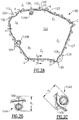
- FIG 2A shows a seal plate 100 which may be utilized at the location of the seal plate 17 of Figure 1 .
- Seal plate 100 includes a plurality of bolt hole ears 102 extending from an outer side of a seal plate body 103. Ears 102 contain bolt holes to receive bolts used to secure housings 18 and 19 together. Also, two alignment pin hole ears 200 are included.
- the seal plate body 103 surrounds an interior space 105 which will be within the housings. There are also oil passage ears 104 inward of the body 103 and within the space 105.
- the oil passage ears 104A and 104B are formed at distinct locations.
- the seal plate 100 can be defined as including six basic extending sides Z1-Z6.
- Z1 is defined between a point A and a point B.
- Z2 is defined between a point B and a point C.
- Z3 is defined between a point C and a point D.
- Z4 is defined between a point D and a point E.
- Z5 is defined between a point E and a point F.
- Z6 is defined between a point F and point A.
- the zone Z1 includes three bolt hole ears 102 and the oil passage ear 104A. As can be appreciated, none of the zones Z1-Z6 extend exactly straight, however, the directions of the zone Z1-Z6 are all generally straight.
- the Z1 zone extends along a first direction towards zone Z2.
- Zone Z2 extends at an angle in a second direction away from Z1 and towards Z3.
- the zone Z2 includes four bolt hole ears.
- the zone Z3 could be said to extend back in a direction having a component opposed to the first direction towards Z4.
- the zone Z3 includes six bolt hole ears and one alignment pin hole ear 200.
- the zone Z4 could be seen to extend in a direction from the end of the zone Z3 towards Z5.
- the Z4 zone includes three bolt hole ears.
- the zone Z5 can be seen to extend further in a direction having a component opposed to the first direction, but also back toward the first zone Z1.
- the zone Z5 includes five bolt hole ears and one oil passage ear 104B.
- the zone Z6 can be seen to extend with a component in the first direction and back to connect to an end of the first zone Z1.
- Z6 includes three bolt hole ears and one alignment pin hole ear 200.
- one bolt hole ear 109 is positioned on an opposed side of the body 103 from both oil passage ears 104A and 104B.
- a group of ears 108 in zone three actually includes two bolt hole ears 109 and one alignment pin ear 200. Others of the bolt hole ears generally have a thinner section 107 separating the bolt hole ears from the most adjacent bolt hole ear, and each of the bolt hole ears 102 including a single bolt hole.
- a second group of ears 111 includes two bolt hole ears 105 and an alignment pin hole ear 200, and is in zone six.
- Figure 2B illustrates details of the oil return ear 104A.
- a distance between a line that bisects the bolt hole ear 109 and the oil passage ear 104A and between the furthest spaced surfaces is defined as d 1 .
- d 1 was between 1.8 and 2.2.
- a diameter of the oil passage hole in oil return ear 104A was 1.03 cm (.406 inch).
- a diameter of all the bolt holes in the bolt hole ears 102/109 was 0.71 cm (0.281 inch).
- a diameter of the oil passage ear 104B was 1.8 cm (.710 inch).
- a distance d 2 between the outer surface of the bolt hole ear 109 and the oil return ear 104B is defined as d 2 .
- d 2 was between 2.1 and 2.5.
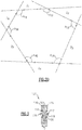
- Figure 2D shows geometric relationship across the six zones or sides Z1-Z6. If a line is drawn bisecting the outermost bolt holes at the outermost extents of each zones Z1-Z6, those lines would intersect as shown in Figure 2D .
- An included angle A 16 in one embodiment was 145° and in embodiments was between 135 and 155°.
- Included angle A 12 in one embodiment was 150°, and in embodiments is between 140 and 160°.
- Included angles A 23 in one embodiment was 95°, and in embodiments is between 85 and 105°.
- Included angle A 34 in one embodiment was 115°, and is embodiments is between 105 and 125°.
- Included angle A 45 in one embodiment was 125°, and is embodiments is between 115 and 135°.
- Included angle A 56 in one embodiment was 160°, and is embodiments is between 90 and 110°.
- the approximate location of the outermost bolt holes utilized to define each of the lines is shown by an X in Figure 2D . It should be understood that the lines illustrated may extend to intersect other lines outside the seal plate body 103.
- Figure 3 is a cross-sectional view along line 3-3. As shown, the body 103 extends between ends 110 and 112. A third distance d 3 , which may be called a thickness, is defined between the ends 110 and 112. In an embodiment, d 3 was 0.32 cm (125 inch).
- a ratio of d 1 to d 3 was between 14.4 and 17.6.
- a ratio of d 2 to d 3 is between 16.8 and 20.0.
- a ratio of the diameter of the oil passage hole in the ear 104B to d 3 is between 5.5 and 5.9.
- a ratio of the diameter of the oil passage hole in ear 104A to the distance d 3 is between 3.1 and 3.5.
- a ratio of the diameter of the bolt holes in the bolt hole ears 102/109 to the distance d 3 is between 2.0 and 2.5.
- a central channel 114 formed in the body 103 and a sealing gasket 106 is formed in the cavity 114 and has a central enlarged nub 117 spaced by nub ditches 118 and outer extending areas 120.
- the body 103 was formed of aluminum and the gasket 116 was formed of an elastomer.
- the seal plate body 103 could be said to include a thinner portion at channel 114, and receives a seal member 116 having outwardly extending nub 117.
- a method of replacing a seal plate in an integrated drive generator comprises the steps of removing an existing seal plate from an integrated drive generator.
- the generator has an input shaft for driving a differential, and the differential is connected for driving a generator rotor.
- a housing surrounds the integrated drive generator, and includes two housing portions.
- the existing seal plate is positioned between the two housing portions. The two housing portions are secured with a plurality of bolts.
- the method includes the further step of replacing the existing seal plate with a replacement seal plate.
- the replacement seal plate may be as disclosed herein.
Landscapes
- Engineering & Computer Science (AREA)
- General Engineering & Computer Science (AREA)
- Mechanical Engineering (AREA)
- Chemical & Material Sciences (AREA)
- Combustion & Propulsion (AREA)
- General Details Of Gearings (AREA)
- Sealing Devices (AREA)
Description
- This application relates to a seal plate positioned between two housing portions in an integrated drive generator.
- Integrated drive generators are known and often utilized in aircraft. As known, a gas turbine engine on the aircraft provides a drive input into a generator input shaft. The generator typically includes a disconnect shaft that can transmit the input into a gear differential. The gear differential selectively drives a main generator to provide electric power for various uses on the aircraft.
- It is desirable that the generated power be of a desired constant frequency. However, the speed from the input shaft will vary during operation of the gas turbine engine. This would result in variable frequency.
- Integrated drive generators are provided with speed trimming hydraulic units. Gears associated with the differential and, in particular, a ring gear portion, provide rotation from the differential back into the trimming unit. A carrier also rotates another portion of the trimming unit. The trimming unit is operable to result in the output speed of the differential being effectively constant, such that electric power of a desirable frequency is generated.
- The generator is mounted between two housing portions and a seal plate is mounted between the two housing portions.
- In addition, various accessory systems, such as various pumps, are driven by the carrier of the differential through an accessory drive gear.
- As can be appreciated, an integrated drive generator must be fully sealed. There are design challenges for the seal plate.
- A seal plate body has a first the zone including three bolt hole ears and an oil passage ear. A second zone includes four bolt hole ears. A third zone includes six bolt ears and one alignment pin hole ear. A fourth zone has three bolt hole ears. A fifth zone includes five bolt hole ears and one oil passage ear. A sixth zone includes three bolt hole ears and one bolt hole ear. Each of the bolt hole ears include a bolt hole, and each of the oil passage ears include an oil passage hole. An integrated drive generator and a method are also disclosed.
- These and other features may be best understood from the following drawings and specification.
-
-
Figure 1 schematically shows an integrated drive generator. -
Figure 2A shows a disclosed seal plate. -
Figure 2B shows a first detail. -
Figure 2C shows a second detail. -
Figure 2D shows another aspect. -
Figure 3 is a cross-sectional view through line 3-3. -
Figure 1 shows anintegrated drive generator 20. As shown,housing portions seal plate 17 sits between thehousing portions seal plate 17 seals oil within the housing. As shown schematically, at certain locations, bolts B and alignment pins A extend through holes in the seal plate to secure and alignhousing portions 18/19. - A
gas turbine engine 22 may drive aninput shaft 23 which selectively drives adisconnect assembly 26. Thedisconnect assembly 26, in turn, drives acarrier shaft 28, which drives a carrier in agear differential 30. - As the
carrier shaft 28 rotates,planet gears gear interface 42 with a firstring gear portion 40. Gears 36 have a gear interface 48 with a second ring gear portion 46. -
Ring gear portion 40 has agear interface 50 with a maingenerator drive gear 52. Whendrive gear 52 is driven to rotate, it rotates arotor 56 associated with astator 58 of the main generator as well as anexciter rotor 60. Electric power is generated for ause 62, as known. - It is desirable that the frequency of the generated electric power be at a desired frequency. This requires the input speed to
gear 52 to be relatively constant and at the desired speed. As such, the speed of theinput shaft 23 is added to the speed of thespeed trimmer 66 to result in a constant input speed togear 52. - A
gear 15 that is part of the carrier has agear interface 16 with agear 13 driving ashaft 14 also within the speed trimmer. - As known, the
speed trimmer 66 includes avariable unit 72 and afixed unit 76. Theunits gear 13 is too high, the speed of thegear 52 will also be too high, and hence, the speed trimmer 66 acts to lower the speed of the trim gear 46 which will drop the speed ofgear 52. On the other hand, if the input speed is too low, the speed trimmer will increase the trim gear speed and he speed seen bygear 52 will increase. - In essence, the
variable unit 72 receives an input throughgear 13 that is proportional to the speed of theinput shaft 23. Thevariable unit 72 also receives a control input from a control monitoring the speed of thegenerator rotor 56. The position of the swash plate in thevariable unit 72 is changed to in turn change the speed and direction of thefixed unit 76. Thefixed unit 76 can change the speed, and direction of rotation of theshaft 70, and this then provides control back through the trim ring gear 46 to change the speed reaching the generator. In this manner, the speed trimmer 66 results in the frequency generated by the generator being closer to constant, and at the desired frequency. - A
permanent magnet generator 32 rotates with thering gear 40. - An
accessory drive shaft 29 rotates with thecarrier shaft 28 and drives a plurality of accessory gears 31. - The operation of the integrated
drive generator 20 is generally as known in the art. A worker of ordinary skill would recognize that the desired frequency and speed atuse 62 would dictate a number of design functions. -
Figure 2A shows aseal plate 100 which may be utilized at the location of theseal plate 17 ofFigure 1 .Seal plate 100 includes a plurality of bolt hole ears 102 extending from an outer side of aseal plate body 103. Ears 102 contain bolt holes to receive bolts used to securehousings pin hole ears 200 are included. As can be appreciated, theseal plate body 103 surrounds aninterior space 105 which will be within the housings. There are also oil passage ears 104 inward of thebody 103 and within thespace 105. - The
oil passage ears - The
seal plate 100 can be defined as including six basic extending sides Z1-Z6. Z1 is defined between a point A and a point B. Z2 is defined between a point B and a point C. Z3 is defined between a point C and a point D. Z4 is defined between a point D and a point E. Z5 is defined between a point E and a point F. Z6 is defined between a point F and point A. - The zone Z1 includes three bolt hole ears 102 and the
oil passage ear 104A. As can be appreciated, none of the zones Z1-Z6 extend exactly straight, however, the directions of the zone Z1-Z6 are all generally straight. The Z1 zone extends along a first direction towards zone Z2. - Zone Z2 extends at an angle in a second direction away from Z1 and towards Z3. The zone Z2 includes four bolt hole ears.
- The zone Z3 could be said to extend back in a direction having a component opposed to the first direction towards Z4. The zone Z3 includes six bolt hole ears and one alignment
pin hole ear 200. - The zone Z4 could be seen to extend in a direction from the end of the zone Z3 towards Z5. The Z4 zone includes three bolt hole ears.
- The zone Z5 can be seen to extend further in a direction having a component opposed to the first direction, but also back toward the first zone Z1. The zone Z5 includes five bolt hole ears and one
oil passage ear 104B. - The zone Z6 can be seen to extend with a component in the first direction and back to connect to an end of the first zone Z1. Z6 includes three bolt hole ears and one alignment
pin hole ear 200. - Notably, one
bolt hole ear 109 is positioned on an opposed side of thebody 103 from bothoil passage ears - In an embodiment, there are thus 24 bolt holes and two alignment pin holes.
- As also shown, a group of
ears 108 in zone three actually includes twobolt hole ears 109 and onealignment pin ear 200. Others of the bolt hole ears generally have athinner section 107 separating the bolt hole ears from the most adjacent bolt hole ear, and each of the bolt hole ears 102 including a single bolt hole. A second group ofears 111 includes twobolt hole ears 105 and an alignmentpin hole ear 200, and is in zone six. -
Figure 2B illustrates details of theoil return ear 104A. A distance between a line that bisects thebolt hole ear 109 and theoil passage ear 104A and between the furthest spaced surfaces is defined as d1. In one embodiment, d1 was between 1.8 and 2.2. A diameter of the oil passage hole inoil return ear 104A was 1.03 cm (.406 inch). A diameter of all the bolt holes in the bolt hole ears 102/109 was 0.71 cm (0.281 inch). - As shown in
Figure 2C , a diameter of theoil passage ear 104B was 1.8 cm (.710 inch). A distance d2 between the outer surface of thebolt hole ear 109 and theoil return ear 104B is defined as d2. In one embodiment, d2 was between 2.1 and 2.5. -
Figure 2D shows geometric relationship across the six zones or sides Z1-Z6. If a line is drawn bisecting the outermost bolt holes at the outermost extents of each zones Z1-Z6, those lines would intersect as shown inFigure 2D . - There are interior included angles between the intersecting lines. An included angle A16 in one embodiment was 145° and in embodiments was between 135 and 155°. Included angle A12 in one embodiment was 150°, and in embodiments is between 140 and 160°. Included angles A23 in one embodiment was 95°, and in embodiments is between 85 and 105°. Included angle A34 in one embodiment was 115°, and is embodiments is between 105 and 125°. Included angle A45 in one embodiment was 125°, and is embodiments is between 115 and 135°. Included angle A56 in one embodiment was 160°, and is embodiments is between 90 and 110°. The approximate location of the outermost bolt holes utilized to define each of the lines is shown by an X in
Figure 2D . It should be understood that the lines illustrated may extend to intersect other lines outside theseal plate body 103. -
Figure 3 is a cross-sectional view along line 3-3. As shown, thebody 103 extends between ends 110 and 112. A third distance d3, which may be called a thickness, is defined between theends 110 and 112. In an embodiment, d3 was 0.32 cm (125 inch). - In embodiments, a ratio of d1 to d3 was between 14.4 and 17.6. A ratio of d2 to d3 is between 16.8 and 20.0. A ratio of the diameter of the oil passage hole in the
ear 104B to d3 is between 5.5 and 5.9. A ratio of the diameter of the oil passage hole inear 104A to the distance d3 is between 3.1 and 3.5. A ratio of the diameter of the bolt holes in the bolt hole ears 102/109 to the distance d3 is between 2.0 and 2.5. - As further shown, there is a
central channel 114 formed in thebody 103 and a sealinggasket 106 is formed in thecavity 114 and has a centralenlarged nub 117 spaced by nubditches 118 and outer extendingareas 120. - In one embodiment, the
body 103 was formed of aluminum and thegasket 116 was formed of an elastomer. - The
seal plate body 103 could be said to include a thinner portion atchannel 114, and receives aseal member 116 having outwardly extendingnub 117. There areseal members 116 on two opposed sides of theseal plate body 103, and extending along each of the six sides of theseal plate body 103 with the nubs having outer surfaces spaced by each from each other by a distance that is greater than the thickness d3 of the seal plate body. - A method of replacing a seal plate in an integrated drive generator comprises the steps of removing an existing seal plate from an integrated drive generator. The generator has an input shaft for driving a differential, and the differential is connected for driving a generator rotor. A housing surrounds the integrated drive generator, and includes two housing portions. The existing seal plate is positioned between the two housing portions. The two housing portions are secured with a plurality of bolts.
- The method includes the further step of replacing the existing seal plate with a replacement seal plate. The replacement seal plate may be as disclosed herein.
- Although an embodiment of this invention has been disclosed, a worker of ordinary skill in this art would recognize that certain modifications would come within the scope of this invention. For that reason, the following claims should be studied to determine the true scope and content of this invention.
Claims (9)
- A seal plate (100) suitable for use in an integrated drive generator (20) comprising:a seal plate body (103) having six zones (Z1 ... Z6), all of the zones are generally straight but not entirely straight;a first zone (Z1) of the zones includes three bolt hole ears (166) and an oil passage ear (104A), the first zone (Z1) extends along a first direction towards a second of the zones (Z2);the second zone (Z2) extends at an angle in a second direction away from the first zone (Z1), the second direction having a component extending in an opposite direction relative to the first direction, and towards a third of the zones (Z3), the second zone (Z2) includes four bolt hole ears;the third zone (Z3) extends in a direction having a component opposed to the first direction towards a fourth of the zones (Z4), the third zone (Z3) includes six bolt hole ears and one alignment pin ear (200);the fourth zone (Z4) extends from an end of the third zone (Z3) towards a fifth of the zones (Z5), the fourth zone (Z4) includes three bolt hole ears;the fifth zone (Z5) extends in a direction with a component in the second direction, and also with a component back toward the first zone (Z1), the fifth zone (Z5) includes five bolt hole ears and one oil passage ear (104B);a sixth zone (Z6) of the zones extends from an end of the fifth zone (Z5) in a direction with a component in the first direction and back to connect to an end of the first zone (Z1), the sixth zone (Z6) includes three bolt hole ears and one alignment pin ear (200); andeach of the bolt hole ears (106) including a bolt hole, and each of the oil passage ears (104A, 104B) including an oil passage hole.
- The seal plate as set forth in claim 1, wherein one of the bolt hole ears is aligned on an opposed side of the seal plate body (103) from the oil passage ear (104B) in the fifth zone (Z5), and a first distance is defined from a first position on an outer surface of the fifth side aligned bolt hole ear to a second position on an inner surface of the oil passage ear (104B) in the fifth zone (Z5) spaced furthest from the first position on a line bisecting both the bolt hole in the aligned bolt hole ear and the oil passage ear (104B) in the fifth zone (Z5), with a thickness of the seal plate body (103) also being defined and a ratio of the first distance to the thickness being between 16.8 and 20.0.
- The seal plate as set forth in claim 2, wherein one of the bolt hole ears is aligned on an opposed side of the seal plate body (103) from the oil passage ear (104A) in the first zone (Z1), a second distance is defined from a first position on an outer surface of the first zone (Z1) aligned bolt hole ear to a second position on an inner surface of the oil passage ear (104A) in the first zone (Z1) spaced furthest from the first position on a line bisecting both the bolt hole in the aligned bolt hole and the oil passage ear (104A) in the first zone (Z1), and a ratio of the second distance to the thickness being between 14.4 and 17.6.
- The seal plate as set forth in claim 3, wherein a corresponding line is defined for each of the zones, the line being drawn bisecting outermost bolt holes in the bolt hole ears at outermost extents of each of the zones, the lines intersecting to define included angles facing an interior of the seal plate body, an included angle between the sixth (Z6) and first zones (Z1) between 135 and 155°, an included angle between the first (Z1) and second zones (Z2) between 140 and 160°, an included angle between the second (Z2) and third zones (Z3) between 85 and 105°, an included angle between the third (Z3) and fourth zones (Z4) between 105 and 125°, an included angle between the fourth (Z4) and fifth zones (Z5) between 115 and 135°, and an included angle between the fifth (Z5) and sixth zones (Z6) between 90 and 110°.
- The seal plate as set forth in claim 4, wherein each of the bolt holes in the bolt hole ears defining a bolt hole diameter, and a ratio of the bolt hole diameter to the thickness being between 5.5 and 5.9, the oil passage hole in the first zone (Z1) having a first zone oil passage hole diameter, and a ratio of the first oil passage hole diameter to the thickness being between 3.1 and 3.5, and the oil passage hole in the fifth zone (Z5) having a fifth zone oil passage hole diameter, and a ratio of the fifth zone oil passage hole diameter to the thickness being between 2.0 and 2.5.
- The seal plate as set forth in claim 1, wherein a corresponding line is defined for each of the zones, the line being drawn bisecting outermost bolt holes in the bolt hole ears at outermost extents of each of the zones, the lines intersecting to define included angles facing an interior of the seal plate body, an included angle between the sixth (Z6) and first zones (Z1) between 135 and 155°, an included angle between the first (Z1) and second zones (Z2) between 140 and 160°, an included angle between the second (Z2) and third zones (Z3) between 85 and 105°, an included angle between the third (Z3) and fourth zones (Z4) between 105 and 125°, an included angle between the fourth (Z4) and fifth zones (Z5) between 115 and 135°, and an included angle between the fifth (Z5) and sixth zones (Z6) between 90 and 110°.
- The seal plate as set forth in claim 1, wherein each of the bolt holes in the bolt hole ears defining a bolt hole diameter, and a ratio of the bolt hole diameter to the thickness being between 5.5 and 5.9, the oil passage hole in the first zone (Z1) having a first zone oil passage hole diameter, and a ratio of the first oil passage hole diameter to a thickness of the seal plate body (103) being between 3.1 and 3.5, and the oil passage hole in the fifth zone (Z5) having a fifth zone oil passage hole diameter, and a ratio of the fifth zone oil passage hole diameter to the thickness being between 2.0 and 2.5.
- An integrated drive generator (20) comprising:an input shaft (23) for driving a differential, the differential connected for driving a generator rotor;a housing surrounding the integrated drive generator (20), and including two housing portions (18, 19), with a seal plate as claimed in any preceding claim, positioned between the two housing portions, and securing the two housing portions secured with a plurality of bolts.
- A method of replacing a seal plate in an integrated drive generator (20) comprising the steps of:removing an existing seal plate from an integrated drive generator (20) having an input shaft (23) for driving a differential, the differential connected for driving a generator rotor, a housing surrounding the integrated drive generator, and including two housing portions (18, 19), with the existing seal plate positioned between the two housing portions (18, 19), and the two housing portions (18, 19) being secured with a plurality of bolts; andreplacing the existing seal plate with a seal plate according to any one of claims 1 to 6.
Applications Claiming Priority (1)
| Application Number | Priority Date | Filing Date | Title |
|---|---|---|---|
| US15/723,495 US10533499B2 (en) | 2017-10-03 | 2017-10-03 | Seal plate located between two housing portions in an integrated drive generator |
Publications (2)
| Publication Number | Publication Date |
|---|---|
| EP3473896A1 EP3473896A1 (en) | 2019-04-24 |
| EP3473896B1 true EP3473896B1 (en) | 2021-04-28 |
Family
ID=63713714
Family Applications (1)
| Application Number | Title | Priority Date | Filing Date |
|---|---|---|---|
| EP18197716.6A Active EP3473896B1 (en) | 2017-10-03 | 2018-09-28 | Seal plate located between two housing portions in an integrated drive generator |
Country Status (2)
| Country | Link |
|---|---|
| US (1) | US10533499B2 (en) |
| EP (1) | EP3473896B1 (en) |
Family Cites Families (12)
| Publication number | Priority date | Publication date | Assignee | Title |
|---|---|---|---|---|
| US6173966B1 (en) | 1997-10-06 | 2001-01-16 | Freudenberg-Nok General Partnership | T-joint gasket assembly |
| US6418714B1 (en) * | 1999-10-22 | 2002-07-16 | Honeywell International, Inc. | Accumulator utilizing housing case pressure |
| US6367248B1 (en) * | 1999-10-22 | 2002-04-09 | Honeywell International Inc. | Active hydraulic control pressure system for adverse “G” flight conditions |
| US20110072634A1 (en) | 2005-04-08 | 2011-03-31 | Kamibayashiyama Julian F | Wedging retainer gasket construction |
| JP4700113B2 (en) * | 2009-02-06 | 2011-06-15 | 川崎重工業株式会社 | Aircraft generator |
| US9006942B2 (en) * | 2009-05-07 | 2015-04-14 | Hamilton Sundstrand Corporation | Generator main stator back-iron cooling sleeve |
| US8454326B2 (en) * | 2009-05-08 | 2013-06-04 | Hamilton Sundstrand Corporation | Idler gear and journal bearing assembly for a generator |
| US8316880B2 (en) * | 2009-05-08 | 2012-11-27 | Hamilton Sundstrand Corporation | Oil filter bypass valve assembly for a generator |
| CN103459807B (en) * | 2011-04-07 | 2016-08-17 | 川崎重工业株式会社 | aircraft generator |
| US9115794B2 (en) * | 2012-07-06 | 2015-08-25 | Hamilton Sundstrand Corporation | Integrated drive generator pump plate |
| EP3019722B1 (en) | 2013-07-09 | 2018-11-21 | United Technologies Corporation | Plated polymer components for a gas turbine engine |
| US9759305B2 (en) * | 2015-04-02 | 2017-09-12 | Hamilton Sundstrand Corporation | Planet gear for an integrated drive generator |
-
2017
- 2017-10-03 US US15/723,495 patent/US10533499B2/en active Active
-
2018
- 2018-09-28 EP EP18197716.6A patent/EP3473896B1/en active Active
Non-Patent Citations (1)
| Title |
|---|
| None * |
Also Published As
| Publication number | Publication date |
|---|---|
| US10533499B2 (en) | 2020-01-14 |
| EP3473896A1 (en) | 2019-04-24 |
| US20190101059A1 (en) | 2019-04-04 |
Similar Documents
| Publication | Publication Date | Title |
|---|---|---|
| EP3511550B1 (en) | Terminal lead support for use in integrated drive generator | |
| US10763722B2 (en) | Terminal block for use in integrated drive generator | |
| US10533499B2 (en) | Seal plate located between two housing portions in an integrated drive generator | |
| EP3514351B1 (en) | Port plate for integrated drive generator | |
| EP3514398B1 (en) | Fixed block shaft inner bearing race for integrated drive generator | |
| EP3509199B1 (en) | Main generator stator sleeve for integrated drive generator | |
| US10599165B2 (en) | Governor and inversion pump drive gear | |
| EP3511594B1 (en) | Fixed block shaft for integrated drive generator | |
| EP3514324B1 (en) | Cam liner for integrated drive generator | |
| EP3467349B1 (en) | Accessory drive gear for integrated drive generator | |
| EP3511521B1 (en) | Pump sleeve for a charge and scavenge pump of an integrated drive generator | |
| EP3502514B1 (en) | Output ring gear for integrated drive generator | |
| EP3511595B1 (en) | Variable block shaft for integrated drive generator | |
| EP3486529B1 (en) | Scavenge/charge pump drive gear for integrated drive generator | |
| EP3489532B1 (en) | Wear ring for integrated drive generator | |
| US10760665B2 (en) | Governor drive gear for integrated drive generator | |
| US20200158119A1 (en) | Seal arrangement for superchargers |
Legal Events
| Date | Code | Title | Description |
|---|---|---|---|
| PUAI | Public reference made under article 153(3) epc to a published international application that has entered the european phase |
Free format text: ORIGINAL CODE: 0009012 |
|
| STAA | Information on the status of an ep patent application or granted ep patent |
Free format text: STATUS: THE APPLICATION HAS BEEN PUBLISHED |
|
| AK | Designated contracting states |
Kind code of ref document: A1 Designated state(s): AL AT BE BG CH CY CZ DE DK EE ES FI FR GB GR HR HU IE IS IT LI LT LU LV MC MK MT NL NO PL PT RO RS SE SI SK SM TR |
|
| AX | Request for extension of the european patent |
Extension state: BA ME |
|
| STAA | Information on the status of an ep patent application or granted ep patent |
Free format text: STATUS: REQUEST FOR EXAMINATION WAS MADE |
|
| 17P | Request for examination filed |
Effective date: 20190731 |
|
| RBV | Designated contracting states (corrected) |
Designated state(s): AL AT BE BG CH CY CZ DE DK EE ES FI FR GB GR HR HU IE IS IT LI LT LU LV MC MK MT NL NO PL PT RO RS SE SI SK SM TR |
|
| STAA | Information on the status of an ep patent application or granted ep patent |
Free format text: STATUS: EXAMINATION IS IN PROGRESS |
|
| 17Q | First examination report despatched |
Effective date: 20191118 |
|
| GRAP | Despatch of communication of intention to grant a patent |
Free format text: ORIGINAL CODE: EPIDOSNIGR1 |
|
| STAA | Information on the status of an ep patent application or granted ep patent |
Free format text: STATUS: GRANT OF PATENT IS INTENDED |
|
| INTG | Intention to grant announced |
Effective date: 20201119 |
|
| GRAS | Grant fee paid |
Free format text: ORIGINAL CODE: EPIDOSNIGR3 |
|
| GRAA | (expected) grant |
Free format text: ORIGINAL CODE: 0009210 |
|
| STAA | Information on the status of an ep patent application or granted ep patent |
Free format text: STATUS: THE PATENT HAS BEEN GRANTED |
|
| AK | Designated contracting states |
Kind code of ref document: B1 Designated state(s): AL AT BE BG CH CY CZ DE DK EE ES FI FR GB GR HR HU IE IS IT LI LT LU LV MC MK MT NL NO PL PT RO RS SE SI SK SM TR |
|
| REG | Reference to a national code |
Ref country code: GB Ref legal event code: FG4D |
|
| REG | Reference to a national code |
Ref country code: CH Ref legal event code: EP |
|
| REG | Reference to a national code |
Ref country code: AT Ref legal event code: REF Ref document number: 1387428 Country of ref document: AT Kind code of ref document: T Effective date: 20210515 |
|
| REG | Reference to a national code |
Ref country code: DE Ref legal event code: R096 Ref document number: 602018016120 Country of ref document: DE |
|
| REG | Reference to a national code |
Ref country code: IE Ref legal event code: FG4D |
|
| REG | Reference to a national code |
Ref country code: LT Ref legal event code: MG9D |
|
| REG | Reference to a national code |
Ref country code: AT Ref legal event code: MK05 Ref document number: 1387428 Country of ref document: AT Kind code of ref document: T Effective date: 20210428 |
|
| PG25 | Lapsed in a contracting state [announced via postgrant information from national office to epo] |
Ref country code: HR Free format text: LAPSE BECAUSE OF FAILURE TO SUBMIT A TRANSLATION OF THE DESCRIPTION OR TO PAY THE FEE WITHIN THE PRESCRIBED TIME-LIMIT Effective date: 20210428 Ref country code: LT Free format text: LAPSE BECAUSE OF FAILURE TO SUBMIT A TRANSLATION OF THE DESCRIPTION OR TO PAY THE FEE WITHIN THE PRESCRIBED TIME-LIMIT Effective date: 20210428 Ref country code: FI Free format text: LAPSE BECAUSE OF FAILURE TO SUBMIT A TRANSLATION OF THE DESCRIPTION OR TO PAY THE FEE WITHIN THE PRESCRIBED TIME-LIMIT Effective date: 20210428 Ref country code: BG Free format text: LAPSE BECAUSE OF FAILURE TO SUBMIT A TRANSLATION OF THE DESCRIPTION OR TO PAY THE FEE WITHIN THE PRESCRIBED TIME-LIMIT Effective date: 20210728 Ref country code: AT Free format text: LAPSE BECAUSE OF FAILURE TO SUBMIT A TRANSLATION OF THE DESCRIPTION OR TO PAY THE FEE WITHIN THE PRESCRIBED TIME-LIMIT Effective date: 20210428 Ref country code: NL Free format text: LAPSE BECAUSE OF FAILURE TO SUBMIT A TRANSLATION OF THE DESCRIPTION OR TO PAY THE FEE WITHIN THE PRESCRIBED TIME-LIMIT Effective date: 20210428 |
|
| PG25 | Lapsed in a contracting state [announced via postgrant information from national office to epo] |
Ref country code: LV Free format text: LAPSE BECAUSE OF FAILURE TO SUBMIT A TRANSLATION OF THE DESCRIPTION OR TO PAY THE FEE WITHIN THE PRESCRIBED TIME-LIMIT Effective date: 20210428 Ref country code: PL Free format text: LAPSE BECAUSE OF FAILURE TO SUBMIT A TRANSLATION OF THE DESCRIPTION OR TO PAY THE FEE WITHIN THE PRESCRIBED TIME-LIMIT Effective date: 20210428 Ref country code: PT Free format text: LAPSE BECAUSE OF FAILURE TO SUBMIT A TRANSLATION OF THE DESCRIPTION OR TO PAY THE FEE WITHIN THE PRESCRIBED TIME-LIMIT Effective date: 20210830 Ref country code: NO Free format text: LAPSE BECAUSE OF FAILURE TO SUBMIT A TRANSLATION OF THE DESCRIPTION OR TO PAY THE FEE WITHIN THE PRESCRIBED TIME-LIMIT Effective date: 20210728 Ref country code: SE Free format text: LAPSE BECAUSE OF FAILURE TO SUBMIT A TRANSLATION OF THE DESCRIPTION OR TO PAY THE FEE WITHIN THE PRESCRIBED TIME-LIMIT Effective date: 20210428 Ref country code: RS Free format text: LAPSE BECAUSE OF FAILURE TO SUBMIT A TRANSLATION OF THE DESCRIPTION OR TO PAY THE FEE WITHIN THE PRESCRIBED TIME-LIMIT Effective date: 20210428 Ref country code: IS Free format text: LAPSE BECAUSE OF FAILURE TO SUBMIT A TRANSLATION OF THE DESCRIPTION OR TO PAY THE FEE WITHIN THE PRESCRIBED TIME-LIMIT Effective date: 20210828 Ref country code: GR Free format text: LAPSE BECAUSE OF FAILURE TO SUBMIT A TRANSLATION OF THE DESCRIPTION OR TO PAY THE FEE WITHIN THE PRESCRIBED TIME-LIMIT Effective date: 20210729 |
|
| REG | Reference to a national code |
Ref country code: NL Ref legal event code: MP Effective date: 20210428 |
|
| PG25 | Lapsed in a contracting state [announced via postgrant information from national office to epo] |
Ref country code: DK Free format text: LAPSE BECAUSE OF FAILURE TO SUBMIT A TRANSLATION OF THE DESCRIPTION OR TO PAY THE FEE WITHIN THE PRESCRIBED TIME-LIMIT Effective date: 20210428 Ref country code: CZ Free format text: LAPSE BECAUSE OF FAILURE TO SUBMIT A TRANSLATION OF THE DESCRIPTION OR TO PAY THE FEE WITHIN THE PRESCRIBED TIME-LIMIT Effective date: 20210428 Ref country code: RO Free format text: LAPSE BECAUSE OF FAILURE TO SUBMIT A TRANSLATION OF THE DESCRIPTION OR TO PAY THE FEE WITHIN THE PRESCRIBED TIME-LIMIT Effective date: 20210428 Ref country code: SK Free format text: LAPSE BECAUSE OF FAILURE TO SUBMIT A TRANSLATION OF THE DESCRIPTION OR TO PAY THE FEE WITHIN THE PRESCRIBED TIME-LIMIT Effective date: 20210428 Ref country code: SM Free format text: LAPSE BECAUSE OF FAILURE TO SUBMIT A TRANSLATION OF THE DESCRIPTION OR TO PAY THE FEE WITHIN THE PRESCRIBED TIME-LIMIT Effective date: 20210428 Ref country code: EE Free format text: LAPSE BECAUSE OF FAILURE TO SUBMIT A TRANSLATION OF THE DESCRIPTION OR TO PAY THE FEE WITHIN THE PRESCRIBED TIME-LIMIT Effective date: 20210428 Ref country code: ES Free format text: LAPSE BECAUSE OF FAILURE TO SUBMIT A TRANSLATION OF THE DESCRIPTION OR TO PAY THE FEE WITHIN THE PRESCRIBED TIME-LIMIT Effective date: 20210428 |
|
| REG | Reference to a national code |
Ref country code: DE Ref legal event code: R097 Ref document number: 602018016120 Country of ref document: DE |
|
| PLBE | No opposition filed within time limit |
Free format text: ORIGINAL CODE: 0009261 |
|
| STAA | Information on the status of an ep patent application or granted ep patent |
Free format text: STATUS: NO OPPOSITION FILED WITHIN TIME LIMIT |
|
| REG | Reference to a national code |
Ref country code: DE Ref legal event code: R119 Ref document number: 602018016120 Country of ref document: DE |
|
| 26N | No opposition filed |
Effective date: 20220131 |
|
| REG | Reference to a national code |
Ref country code: CH Ref legal event code: PL |
|
| REG | Reference to a national code |
Ref country code: BE Ref legal event code: MM Effective date: 20210930 |
|
| PG25 | Lapsed in a contracting state [announced via postgrant information from national office to epo] |
Ref country code: IS Free format text: LAPSE BECAUSE OF FAILURE TO SUBMIT A TRANSLATION OF THE DESCRIPTION OR TO PAY THE FEE WITHIN THE PRESCRIBED TIME-LIMIT Effective date: 20210828 Ref country code: MC Free format text: LAPSE BECAUSE OF FAILURE TO SUBMIT A TRANSLATION OF THE DESCRIPTION OR TO PAY THE FEE WITHIN THE PRESCRIBED TIME-LIMIT Effective date: 20210428 Ref country code: AL Free format text: LAPSE BECAUSE OF FAILURE TO SUBMIT A TRANSLATION OF THE DESCRIPTION OR TO PAY THE FEE WITHIN THE PRESCRIBED TIME-LIMIT Effective date: 20210428 |
|
| PG25 | Lapsed in a contracting state [announced via postgrant information from national office to epo] |
Ref country code: LU Free format text: LAPSE BECAUSE OF NON-PAYMENT OF DUE FEES Effective date: 20210928 Ref country code: IT Free format text: LAPSE BECAUSE OF FAILURE TO SUBMIT A TRANSLATION OF THE DESCRIPTION OR TO PAY THE FEE WITHIN THE PRESCRIBED TIME-LIMIT Effective date: 20210428 Ref country code: DE Free format text: LAPSE BECAUSE OF NON-PAYMENT OF DUE FEES Effective date: 20220401 Ref country code: BE Free format text: LAPSE BECAUSE OF NON-PAYMENT OF DUE FEES Effective date: 20210930 Ref country code: IE Free format text: LAPSE BECAUSE OF NON-PAYMENT OF DUE FEES Effective date: 20210928 |
|
| PG25 | Lapsed in a contracting state [announced via postgrant information from national office to epo] |
Ref country code: LI Free format text: LAPSE BECAUSE OF NON-PAYMENT OF DUE FEES Effective date: 20210930 Ref country code: CH Free format text: LAPSE BECAUSE OF NON-PAYMENT OF DUE FEES Effective date: 20210930 |
|
| P01 | Opt-out of the competence of the unified patent court (upc) registered |
Effective date: 20230522 |
|
| PG25 | Lapsed in a contracting state [announced via postgrant information from national office to epo] |
Ref country code: CY Free format text: LAPSE BECAUSE OF FAILURE TO SUBMIT A TRANSLATION OF THE DESCRIPTION OR TO PAY THE FEE WITHIN THE PRESCRIBED TIME-LIMIT Effective date: 20210428 |
|
| PG25 | Lapsed in a contracting state [announced via postgrant information from national office to epo] |
Ref country code: HU Free format text: LAPSE BECAUSE OF FAILURE TO SUBMIT A TRANSLATION OF THE DESCRIPTION OR TO PAY THE FEE WITHIN THE PRESCRIBED TIME-LIMIT; INVALID AB INITIO Effective date: 20180928 |
|
| PG25 | Lapsed in a contracting state [announced via postgrant information from national office to epo] |
Ref country code: MK Free format text: LAPSE BECAUSE OF FAILURE TO SUBMIT A TRANSLATION OF THE DESCRIPTION OR TO PAY THE FEE WITHIN THE PRESCRIBED TIME-LIMIT Effective date: 20210428 |
|
| PG25 | Lapsed in a contracting state [announced via postgrant information from national office to epo] |
Ref country code: MT Free format text: LAPSE BECAUSE OF FAILURE TO SUBMIT A TRANSLATION OF THE DESCRIPTION OR TO PAY THE FEE WITHIN THE PRESCRIBED TIME-LIMIT Effective date: 20210428 |
|
| PGFP | Annual fee paid to national office [announced via postgrant information from national office to epo] |
Ref country code: GB Payment date: 20250820 Year of fee payment: 8 |
|
| PGFP | Annual fee paid to national office [announced via postgrant information from national office to epo] |
Ref country code: FR Payment date: 20250820 Year of fee payment: 8 |
|
| PG25 | Lapsed in a contracting state [announced via postgrant information from national office to epo] |
Ref country code: TR Free format text: LAPSE BECAUSE OF FAILURE TO SUBMIT A TRANSLATION OF THE DESCRIPTION OR TO PAY THE FEE WITHIN THE PRESCRIBED TIME-LIMIT Effective date: 20210428 |