EP3473891A1 - Electric linear actuator and electric brake device - Google Patents
Electric linear actuator and electric brake device Download PDFInfo
- Publication number
- EP3473891A1 EP3473891A1 EP17813104.1A EP17813104A EP3473891A1 EP 3473891 A1 EP3473891 A1 EP 3473891A1 EP 17813104 A EP17813104 A EP 17813104A EP 3473891 A1 EP3473891 A1 EP 3473891A1
- Authority
- EP
- European Patent Office
- Prior art keywords
- carrier
- rotary shaft
- axially
- outer ring
- load
- Prior art date
- Legal status (The legal status is an assumption and is not a legal conclusion. Google has not performed a legal analysis and makes no representation as to the accuracy of the status listed.)
- Withdrawn
Links
Images












Classifications
-
- B—PERFORMING OPERATIONS; TRANSPORTING
- B60—VEHICLES IN GENERAL
- B60T—VEHICLE BRAKE CONTROL SYSTEMS OR PARTS THEREOF; BRAKE CONTROL SYSTEMS OR PARTS THEREOF, IN GENERAL; ARRANGEMENT OF BRAKING ELEMENTS ON VEHICLES IN GENERAL; PORTABLE DEVICES FOR PREVENTING UNWANTED MOVEMENT OF VEHICLES; VEHICLE MODIFICATIONS TO FACILITATE COOLING OF BRAKES
- B60T13/00—Transmitting braking action from initiating means to ultimate brake actuator with power assistance or drive; Brake systems incorporating such transmitting means, e.g. air-pressure brake systems
- B60T13/74—Transmitting braking action from initiating means to ultimate brake actuator with power assistance or drive; Brake systems incorporating such transmitting means, e.g. air-pressure brake systems with electrical assistance or drive
- B60T13/741—Transmitting braking action from initiating means to ultimate brake actuator with power assistance or drive; Brake systems incorporating such transmitting means, e.g. air-pressure brake systems with electrical assistance or drive acting on an ultimate actuator
-
- F—MECHANICAL ENGINEERING; LIGHTING; HEATING; WEAPONS; BLASTING
- F16—ENGINEERING ELEMENTS AND UNITS; GENERAL MEASURES FOR PRODUCING AND MAINTAINING EFFECTIVE FUNCTIONING OF MACHINES OR INSTALLATIONS; THERMAL INSULATION IN GENERAL
- F16D—COUPLINGS FOR TRANSMITTING ROTATION; CLUTCHES; BRAKES
- F16D65/00—Parts or details
- F16D65/14—Actuating mechanisms for brakes; Means for initiating operation at a predetermined position
- F16D65/16—Actuating mechanisms for brakes; Means for initiating operation at a predetermined position arranged in or on the brake
- F16D65/18—Actuating mechanisms for brakes; Means for initiating operation at a predetermined position arranged in or on the brake adapted for drawing members together, e.g. for disc brakes
-
- B—PERFORMING OPERATIONS; TRANSPORTING
- B60—VEHICLES IN GENERAL
- B60T—VEHICLE BRAKE CONTROL SYSTEMS OR PARTS THEREOF; BRAKE CONTROL SYSTEMS OR PARTS THEREOF, IN GENERAL; ARRANGEMENT OF BRAKING ELEMENTS ON VEHICLES IN GENERAL; PORTABLE DEVICES FOR PREVENTING UNWANTED MOVEMENT OF VEHICLES; VEHICLE MODIFICATIONS TO FACILITATE COOLING OF BRAKES
- B60T13/00—Transmitting braking action from initiating means to ultimate brake actuator with power assistance or drive; Brake systems incorporating such transmitting means, e.g. air-pressure brake systems
- B60T13/74—Transmitting braking action from initiating means to ultimate brake actuator with power assistance or drive; Brake systems incorporating such transmitting means, e.g. air-pressure brake systems with electrical assistance or drive
-
- F—MECHANICAL ENGINEERING; LIGHTING; HEATING; WEAPONS; BLASTING
- F16—ENGINEERING ELEMENTS AND UNITS; GENERAL MEASURES FOR PRODUCING AND MAINTAINING EFFECTIVE FUNCTIONING OF MACHINES OR INSTALLATIONS; THERMAL INSULATION IN GENERAL
- F16D—COUPLINGS FOR TRANSMITTING ROTATION; CLUTCHES; BRAKES
- F16D55/00—Brakes with substantially-radial braking surfaces pressed together in axial direction, e.g. disc brakes
- F16D55/02—Brakes with substantially-radial braking surfaces pressed together in axial direction, e.g. disc brakes with axially-movable discs or pads pressed against axially-located rotating members
- F16D55/22—Brakes with substantially-radial braking surfaces pressed together in axial direction, e.g. disc brakes with axially-movable discs or pads pressed against axially-located rotating members by clamping an axially-located rotating disc between movable braking members, e.g. movable brake discs or brake pads
- F16D55/224—Brakes with substantially-radial braking surfaces pressed together in axial direction, e.g. disc brakes with axially-movable discs or pads pressed against axially-located rotating members by clamping an axially-located rotating disc between movable braking members, e.g. movable brake discs or brake pads with a common actuating member for the braking members
- F16D55/225—Brakes with substantially-radial braking surfaces pressed together in axial direction, e.g. disc brakes with axially-movable discs or pads pressed against axially-located rotating members by clamping an axially-located rotating disc between movable braking members, e.g. movable brake discs or brake pads with a common actuating member for the braking members the braking members being brake pads
- F16D55/226—Brakes with substantially-radial braking surfaces pressed together in axial direction, e.g. disc brakes with axially-movable discs or pads pressed against axially-located rotating members by clamping an axially-located rotating disc between movable braking members, e.g. movable brake discs or brake pads with a common actuating member for the braking members the braking members being brake pads in which the common actuating member is moved axially, e.g. floating caliper disc brakes
-
- F—MECHANICAL ENGINEERING; LIGHTING; HEATING; WEAPONS; BLASTING
- F16—ENGINEERING ELEMENTS AND UNITS; GENERAL MEASURES FOR PRODUCING AND MAINTAINING EFFECTIVE FUNCTIONING OF MACHINES OR INSTALLATIONS; THERMAL INSULATION IN GENERAL
- F16D—COUPLINGS FOR TRANSMITTING ROTATION; CLUTCHES; BRAKES
- F16D65/00—Parts or details
- F16D65/14—Actuating mechanisms for brakes; Means for initiating operation at a predetermined position
- F16D65/16—Actuating mechanisms for brakes; Means for initiating operation at a predetermined position arranged in or on the brake
- F16D65/18—Actuating mechanisms for brakes; Means for initiating operation at a predetermined position arranged in or on the brake adapted for drawing members together, e.g. for disc brakes
- F16D65/183—Actuating mechanisms for brakes; Means for initiating operation at a predetermined position arranged in or on the brake adapted for drawing members together, e.g. for disc brakes with force-transmitting members arranged side by side acting on a spot type force-applying member
-
- F—MECHANICAL ENGINEERING; LIGHTING; HEATING; WEAPONS; BLASTING
- F16—ENGINEERING ELEMENTS AND UNITS; GENERAL MEASURES FOR PRODUCING AND MAINTAINING EFFECTIVE FUNCTIONING OF MACHINES OR INSTALLATIONS; THERMAL INSULATION IN GENERAL
- F16D—COUPLINGS FOR TRANSMITTING ROTATION; CLUTCHES; BRAKES
- F16D66/00—Arrangements for monitoring working conditions, e.g. wear, temperature
-
- F—MECHANICAL ENGINEERING; LIGHTING; HEATING; WEAPONS; BLASTING
- F16—ENGINEERING ELEMENTS AND UNITS; GENERAL MEASURES FOR PRODUCING AND MAINTAINING EFFECTIVE FUNCTIONING OF MACHINES OR INSTALLATIONS; THERMAL INSULATION IN GENERAL
- F16H—GEARING
- F16H25/00—Gearings comprising primarily only cams, cam-followers and screw-and-nut mechanisms
- F16H25/18—Gearings comprising primarily only cams, cam-followers and screw-and-nut mechanisms for conveying or interconverting oscillating or reciprocating motions
- F16H25/20—Screw mechanisms
-
- F—MECHANICAL ENGINEERING; LIGHTING; HEATING; WEAPONS; BLASTING
- F16—ENGINEERING ELEMENTS AND UNITS; GENERAL MEASURES FOR PRODUCING AND MAINTAINING EFFECTIVE FUNCTIONING OF MACHINES OR INSTALLATIONS; THERMAL INSULATION IN GENERAL
- F16D—COUPLINGS FOR TRANSMITTING ROTATION; CLUTCHES; BRAKES
- F16D66/00—Arrangements for monitoring working conditions, e.g. wear, temperature
- F16D2066/005—Force, torque, stress or strain
-
- F—MECHANICAL ENGINEERING; LIGHTING; HEATING; WEAPONS; BLASTING
- F16—ENGINEERING ELEMENTS AND UNITS; GENERAL MEASURES FOR PRODUCING AND MAINTAINING EFFECTIVE FUNCTIONING OF MACHINES OR INSTALLATIONS; THERMAL INSULATION IN GENERAL
- F16D—COUPLINGS FOR TRANSMITTING ROTATION; CLUTCHES; BRAKES
- F16D2121/00—Type of actuator operation force
- F16D2121/18—Electric or magnetic
- F16D2121/24—Electric or magnetic using motors
-
- F—MECHANICAL ENGINEERING; LIGHTING; HEATING; WEAPONS; BLASTING
- F16—ENGINEERING ELEMENTS AND UNITS; GENERAL MEASURES FOR PRODUCING AND MAINTAINING EFFECTIVE FUNCTIONING OF MACHINES OR INSTALLATIONS; THERMAL INSULATION IN GENERAL
- F16D—COUPLINGS FOR TRANSMITTING ROTATION; CLUTCHES; BRAKES
- F16D2125/00—Components of actuators
- F16D2125/18—Mechanical mechanisms
- F16D2125/20—Mechanical mechanisms converting rotation to linear movement or vice versa
- F16D2125/34—Mechanical mechanisms converting rotation to linear movement or vice versa acting in the direction of the axis of rotation
- F16D2125/40—Screw-and-nut
-
- F—MECHANICAL ENGINEERING; LIGHTING; HEATING; WEAPONS; BLASTING
- F16—ENGINEERING ELEMENTS AND UNITS; GENERAL MEASURES FOR PRODUCING AND MAINTAINING EFFECTIVE FUNCTIONING OF MACHINES OR INSTALLATIONS; THERMAL INSULATION IN GENERAL
- F16D—COUPLINGS FOR TRANSMITTING ROTATION; CLUTCHES; BRAKES
- F16D2125/00—Components of actuators
- F16D2125/18—Mechanical mechanisms
- F16D2125/44—Mechanical mechanisms transmitting rotation
- F16D2125/46—Rotating members in mutual engagement
- F16D2125/48—Rotating members in mutual engagement with parallel stationary axes, e.g. spur gears
-
- F—MECHANICAL ENGINEERING; LIGHTING; HEATING; WEAPONS; BLASTING
- F16—ENGINEERING ELEMENTS AND UNITS; GENERAL MEASURES FOR PRODUCING AND MAINTAINING EFFECTIVE FUNCTIONING OF MACHINES OR INSTALLATIONS; THERMAL INSULATION IN GENERAL
- F16D—COUPLINGS FOR TRANSMITTING ROTATION; CLUTCHES; BRAKES
- F16D2125/00—Components of actuators
- F16D2125/18—Mechanical mechanisms
- F16D2125/44—Mechanical mechanisms transmitting rotation
- F16D2125/46—Rotating members in mutual engagement
- F16D2125/50—Rotating members in mutual engagement with parallel non-stationary axes, e.g. planetary gearing
-
- F—MECHANICAL ENGINEERING; LIGHTING; HEATING; WEAPONS; BLASTING
- F16—ENGINEERING ELEMENTS AND UNITS; GENERAL MEASURES FOR PRODUCING AND MAINTAINING EFFECTIVE FUNCTIONING OF MACHINES OR INSTALLATIONS; THERMAL INSULATION IN GENERAL
- F16D—COUPLINGS FOR TRANSMITTING ROTATION; CLUTCHES; BRAKES
- F16D2131/00—Overall arrangement of the actuators or their elements, e.g. modular construction
-
- F—MECHANICAL ENGINEERING; LIGHTING; HEATING; WEAPONS; BLASTING
- F16—ENGINEERING ELEMENTS AND UNITS; GENERAL MEASURES FOR PRODUCING AND MAINTAINING EFFECTIVE FUNCTIONING OF MACHINES OR INSTALLATIONS; THERMAL INSULATION IN GENERAL
- F16H—GEARING
- F16H25/00—Gearings comprising primarily only cams, cam-followers and screw-and-nut mechanisms
- F16H25/18—Gearings comprising primarily only cams, cam-followers and screw-and-nut mechanisms for conveying or interconverting oscillating or reciprocating motions
- F16H25/20—Screw mechanisms
- F16H2025/2062—Arrangements for driving the actuator
- F16H2025/2081—Parallel arrangement of drive motor to screw axis
-
- F—MECHANICAL ENGINEERING; LIGHTING; HEATING; WEAPONS; BLASTING
- F16—ENGINEERING ELEMENTS AND UNITS; GENERAL MEASURES FOR PRODUCING AND MAINTAINING EFFECTIVE FUNCTIONING OF MACHINES OR INSTALLATIONS; THERMAL INSULATION IN GENERAL
- F16H—GEARING
- F16H25/00—Gearings comprising primarily only cams, cam-followers and screw-and-nut mechanisms
- F16H25/18—Gearings comprising primarily only cams, cam-followers and screw-and-nut mechanisms for conveying or interconverting oscillating or reciprocating motions
- F16H25/20—Screw mechanisms
- F16H25/22—Screw mechanisms with balls, rollers, or similar members between the co-operating parts; Elements essential to the use of such members
- F16H25/2247—Screw mechanisms with balls, rollers, or similar members between the co-operating parts; Elements essential to the use of such members with rollers
- F16H25/2252—Planetary rollers between nut and screw
Definitions
- the present invention relates to an electric linear motion actuator, and an electromechanical brake system in which the electric linear motion actuator is used.
- hydraulic brake systems driven by oil pressure have been widely used.
- hydraulic brake systems use brake oil, a burden on the environment is high.
- electromechanical brake systems which are driven by an electric motor, are gathering attention.
- Electromechanical brake systems include a brake disk that rotate together with a vehicle wheel; a brake pad opposed to the brake disk; and an electric linear motion actuator for linearly driving the brake pad to press the brake pad against the brake disk, thereby generating a braking force.
- Patent document 1 discloses an electric linear motion actuator used in such electromechanical brake systems, and including an electric motor; a rotary shaft to which the rotation of the electric motor is transmitted; a plurality of planetary rollers kept in rolling contact with the outer periphery of the rotary shaft; a carrier retaining the planetary rollers such that the planetary rollers can revolve around the rotary shaft while rotating about their respective center axes; an outer ring member surrounding the planetary rollers; and a housing in which the outer ring member is axially movably received.
- the outer ring has a helical rib on the inner periphery.
- Each planetary roller has, in the outer periphery, a helical groove or circumferential grooves in which the helical rib is engaged.
- Patent document 1 proposes a structure which enables the load conversion rate to be switched according to the magnitude of the axial load applied to an object by the outer ring member.
- an elastic member supports the carrier such that, due to the axially rearward reaction force which the outer ring member receives when the outer ring member applies an axially forward load to the object, the carrier moves in the axially rearward direction relative to the rotary shaft.
- a frictionally coupling portion is disposed on the outer periphery of the rotary shaft such that, while the carrier has not moved in the axially rearward direction relative to the rotary shaft, the carrier and the frictionally coupling portion are frictionally coupled together so as to restrict the relative rotation of the carrier and the rotary shaft, and such that, when the carrier has moved in the axially rearward direction relative to the rotary shaft, the carrier and the frictionally coupling portion are uncoupled from each other so as to allow the carrier and the rotary shaft to rotate relative to each other.
- the rotation of the rotary shaft transmitted from outside causes the planetary rollers to revolve around the rotary shaft while rotating about their respective center axes, and thus the outer ring member axially moves at a high reduction ratio.
- the load conversion rate reduction ratio
- Patent document 2 discloses a load sensor used in an electromechanical brake system, and configured to detect the magnitude of the axially rearward reaction force which the electric linear motion actuator of the brake system receives when it presses the brake pad against the brake disk.
- This load sensor is disposed to support, through the planetary rollers and the carrier, the axially rearward reaction force which the outer ring member receives from the object when the outer ring member applies an axially forward load to the object.
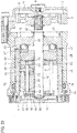
- an electric linear motion actuator 77 including, as illustrated in Fig. 14 , a planetary roller screw type linear motion actuator 74 configured to axially move an outer ring 72 due to the engagement of a helical rib 73 on the inner periphery of the outer ring member 72 in circumferential grooves 71 in the outer peripheries of the planetary rollers 70; and a load sensor 76 configured to support, through the planetary rollers 70 and a carrier 75, the axially rearward reaction force which the outer ring member 72 receives from an object when the outer ring member applies the axially forward load to the object. Then, the inventor conducted an experiment to find the relationship between the magnitude of the axially forward load applied to the object from the outer ring member 72, and the output from the load sensor 76.
- the electric linear motion actuator 77 used in the above experiment includes (though some of the below elements are already mentioned above) a rotary shaft 78 to which the rotation of an electric motor (not shown) is transmitted; plural planetary rollers 70 in rolling contact with the outer periphery of the rotary shaft 78; a carrier 75 which retains the planetary rollers 70 such that the planetary rollers 70 can revolve around the rotary shaft 78 while rotating about their respective center axes; an outer ring member 72 surroundings the planetary rollers 70; a housing 79 in which the outer ring member 72 is axially movably received; a helical rib 73 on the inner periphery of the outer ring member 72; and circumferential grooves 71 in the outer peripheries of the planetary rollers 70.
- the rotary shaft 78 is provided, on its outer periphery, with an frictionally engaging surface 80 configured to restrict the range within which the carrier 75 is movable in the axially forward direction relative to the rotary shaft 78; and a snap ring 81 configured to restrict the range within which the carrier 75 is movable in the axially rearward direction relative to the rotary shaft 78.
- An elastic member 82 is mounted between the carrier 75 and the load sensor 76 so as to bias the carrier 75 in the axially forward direction relative to the rotary shaft 78.
- the frictionally engaging surface 80 comprises a tapered surface configured such that, while the carrier 75 has not moved in the axially rearward direction relative to the rotary shaft 78, the tapered surface and the carrier 75 are frictionally coupled together so as to restrict the relative rotation of the carrier 75 and the rotary shaft 78, and such that, when the carrier 75 has moved in the axially rearward direction relative to the rotary shaft 78, the tapered surface and the carrier 75 are uncoupled from each other so as to allow the carrier 75 and the rotary shaft 78 to rotate relative to each other.
- the load sensor 76 is fixedly mounted at a position axially rearward of the carrier 75.
- the load sensor 76 includes a flange member 83 configured to support the axially rearward reaction force which the outer ring member 72 receives when the outer ring member 72 applies the axially forward load to the object such that the flange member 83 is deflected by the axially rearward reaction force; a circular annular support member 84 disposed axially rearward of the flange member 83; a magnetic target 85 configured to generate a magnetic field; and a magnetism detector 86 configured to detect the magnetic field generated by the magnetic target 85.
- the load sensor 76 is configured such that, as the flange member 83 is deflected, the magnetic target 85 and the magnetism detector 86 are displaced from each other according to the degree of such deflection, and is capable of detecting the magnitude of the reaction force based on the magnetic field which the magnetism detector 86 detects.
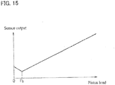
- the reaction force value detected by the load sensor 76 also monotonically increases according to the magnitude of this load.
- reaction force value detected by the load sensor 76 decreased temporarily for the following reasons.
- F OR is the magnitude of the axially rearward reaction force which the outer ring member 72 receives when the outer ring member 72 applies an axially forward load to the object
- Fc is the magnitude of the axial load applied to the load sensor 76 from the carrier 75
- F SR is the magnitude of the axially forward load applied to the load sensor 76 through the snap ring 81
- F H is the magnitude of the axial load which the support member 84 receives from the housing 79
- Fs is the magnitude of the preload applied to the carrier 75 by the elastic member 82 while no axially forward load is being applied to the object by the outer ring member 72
- the reaction force value detected by the load sensor 76 decreases temporarily, since the value detected by the load sensor 76 is not in a one-to-one relationship with the magnitude of the actual reaction force anymore, it is impossible to stably control the magnitude of the axial load based on the value detected by the load sensor 76.
- An object of the present invention is, in an electric linear motion actuator including a carrier axially movably supported by the elastic member, to enable the load sensor to stably detect the axially rearward reaction force which the outer ring member receives from the object when the outer ring member applies the axially forward load to the object.
- an electric linear motion actuator comprising: an electric motor; a rotary shaft to which rotation of the electric motor is to be transmitted; a plurality of planetary rollers in rolling contact with an outer periphery of the rotary shaft, and each having an outer periphery; a carrier retaining the planetary rollers such that the planetary rollers can revolve around the rotary shaft while rotating about respective center axes of the planetary rollers; an outer ring member surrounding the planetary rollers, and supported so as to be axially movable; a housing in which the outer ring member is axially movably received; a helical rib disposed on an inner periphery of the outer ring member; either helical grooves each disposed in the outer periphery of a respective one of the planetary rollers, or circumferential grooves, a plurality of the circumferential grooves being disposed in the outer periphery of a respective one of the planetary rollers, wherein the helical rib
- the load sensor can stably detect the axially rearward reaction force which the outer ring member receives form the object when the outer ring member applies an axially forward load to the object.
- the above electric linear motion actuator may be an actuator wherein the load sensor comprises: a flange member configured to be deflected by the axially rearward reaction force; a circular annular plate-shaped support member disposed axially rearward of the flange member; a magnetic target configured to generate a magnetic field; and a magnetism detector configured to detect the magnetic field generated by the magnetic target, wherein one of the magnetic target and the magnetism detector is fixed to the flange member, and the other of the magnetic target and the magnetism detector is fixed to the circular annular plate-shaped support member such that, as the flange member is deflected, the magnetic target and the magnetism detector are displaced from each other according to a degree of deflection of the flange member, wherein the circular annular plate-shaped support member is disposed between the carrier and the rear engagement portion such that the second axially forward load is applied to the circular annular plate-shaped support member, and wherein the circular annular plate-shaped support member includes, on an axial side surface of the
- the above electric linear motion actuator may be an actuator wherein the load sensor comprises: a flange member configured to be deflected by the axially rearward reaction force; a circular annular plate-shaped support member disposed axially rearward of the flange member; a magnetic target configured to generate a magnetic field; and a magnetism detector configured to detect the magnetic field generated by the magnetic target, wherein one of the magnetic target and the magnetism detector is fixed to the flange member, and the other of the magnetic target and the magnetism detector is fixed to the circular annular plate-shaped support member such that, as the flange member is deflected, the magnetic target and the magnetism detector are displaced from each other according to a degree of deflection of the flange member, wherein the circular annular plate-shaped support member has a radially outer edge, and is disposed between the carrier and the rear engagement portion such that the second axially forward load is applied to the radially outer edge of the circular annular plate-shaped support member such that, even when
- the load sensor may be disposed axially rearward of the rear engagement portion such that, even when the magnitude of the axially forward load applied from the rear engagement portion changes, the reaction force value detected by the load sensor is not affected.
- the electric linear motion actuator may further comprise: a first thrust bearing arranged to allow the carrier and the load sensor to rotate relative to each other, while transmitting any axial load between the carrier and the load sensor; and a second thrust bearing arranged to allow the carrier and the rear engagement portion to rotate relative to each other, while transmitting any axial load between the carrier and the rear engagement portion.
- the front engagement portion may comprise a frictionally coupling surface configured such that, while the carrier has not moved in the axially rearward direction relative to the rotary shaft, the frictionally coupling surface and the carrier are frictionally coupled together so as to restrict a relative rotation of the carrier and the rotary shaft, and such that, when the carrier has moved in the axially rearward direction relative to the rotary shaft, the frictionally coupling surface and the carrier are uncoupled from each other so as to allow the carrier and the rotary shaft to rotate relative to each other.
- the present invention also provides an electromechanical brake system comprising: a brake disk configured to rotate together with a vehicle wheel; a brake pad opposed to the brake disk; and the above-described electric linear motion actuator, which is configured to linearly drive the brake pad.
- the load sensor can stably detect the axially rearward reaction force which the outer ring member receives form the object when the outer ring member applies an axially forward load to the object.
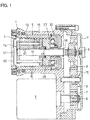
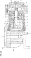
- this electric linear motion actuator 1 includes an electric motor 2; a reduction gear train 3 configured to reduce the rotational speed of the electric motor 2; and a planetary roller screw type linear motion mechanism 5 configured to convert the rotation transmitted from the electric motor 2 through the reduction gear train 3, into a linear motion of an outer ring member 4.
- the reduction gear train 3 includes an input gear 7 fixed to the motor shaft 6 of the electric motor 2; an output gear 9 fixed to a rotary shaft 8 of the planetary roller screw type linear motion mechanism 5; an intermediate gear 10 through which rotation is transmitted from the input gear 7 to the output gear 9; and a gear case 11 in which the gears 7, 9 and 10 are received.
- the respective gears 7, 9 and 10 have teeth different in number from each other.
- the planetary roller screw type linear motion mechanism 5 includes the above-mentioned rotary shaft 8, which has a cylindrical surface 12 on its outer periphery; a plurality of planetary rollers 13 in rolling contact with the cylindrical surface 12; a carrier 14 retaining the planetary rollers 13 such that the planetary rollers 13 can revolve around the rotary shaft 8 while rotating about their respective center axes; the above-mentioned outer ring member 4, which is a hollow tubular member surrounding the planetary rollers 13; and a housing 15 in which the outer ring member 4 is axially movably received.
- the planetary rollers 13 are circumferentially spaced apart from each other between the inner periphery of the outer ring member 4 and the outer periphery of the rotary shaft 8.
- axial refers to the direction parallel to the rotary shaft 8
- axially forward refers to the direction in which the outer ring member 4 moves to protrude from the housing 15
- axially rearward refers to the direction opposite to the axially forward direction, specifically, the direction in which the outer ring member 4 moves into the housing 15 so that its portion protruding from the housing 15 decreases
- circumferential refers to the (circumferential) direction about the rotary shaft 8
- radial refer to a direction orthogonal to the rotary shaft 8.
- the outer ring member 4 has, on its inner periphery, a helical rib 16 having a predetermined lead angle so as to extend obliquely with respect to the circumferential direction.
- Each planetary roller 13 has, in its outer periphery, a plurality of axially spaced apart circumferential grooves 17 in which the helical rib 16 is engaged. The interval between each axially adjacent pair of circumferential grooves 17 is equal in size to the pitch of the helical rib 16.
- each planetary roller 13 may have a helical groove different in lead angle from the helical rib 16.
- the carrier 14 includes a plurality of support pins 18 supporting the respective planetary rollers 13 such that the planetary rollers 13 are rotatable about their respective center axes; an axially front disk 19 retaining the axially front ends of the support pins 18; an axially rear disk 20 retaining the axially rear ends of the support pins 18; and pillars 21 which extend between the respective circumferentially adjacent pairs of planetary rollers 13, and through which the axially front disk 19 and the axially rear disk 20 are fixedly coupled together so as to be unmovable relative to each other in the axial and circumferential directions.
- the axially front disk 19 and the axially rear disk 20 are annular disks through which the rotary shaft 8 extends.
- a sliding bearing 22 is mounted on the inner periphery of the axially rear disk 20, and is in sliding contact with the outer periphery of the rotary shaft 8.
- Radial bearings 23 are mounted between the outer periphery of each support pin 18 and the inner periphery of the planetary roller 13, and support the planetary roller 13 so that the planetary roller 13 is rotatable about its center axis.
- a thrust bearing 24 is mounted between each planetary roller 13 and the axially rear disk 20, and axially supports the planetary roller 13 so that the planetary roller 13 is rotatable about its center axis.
- An aligning seat 25 is mounted between each thrust bearing 24 and the axially rear disk 21, and supports the corresponding planetary roller 13 through the thrust bearing 24 such that the planetary roller 13 is inclinable.
- the outer ring member 4 is axially slidably supported by the inner surface of a receiving hole 26 formed in the housing 15.
- a load sensor 30 is fixedly mounted inside the housing 15 at a position away from the carrier 14 in the axially rearward direction.
- a thrust bearing 27 is mounted between the carrier 14 and the load sensor 30, and supports the carrier 14 from its axially rear side such that the carrier 14 can revolve around the rotary shaft 8.
- a spacer 28 is mounted between the carrier 14 and the thrust bearing 27 such that an axial load is transmitted from the carrier 14 to the thrust bearing 27 through the spacer 28.
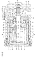
- the load sensor 30 includes a flange member 31 configured to be deflected by the axially rearward reaction force which the outer ring member 4 receives when the outer ring member 4 applies an axially forward load to an object; a circular annular plate-shaped support member 32 disposed axially rearward of the flange member 31; a magnetic target 33 configured to generate a magnetic field; and a magnetism detector 34 configured to detect the magnetic field generated by the magnetic target 33.
- the support member 32 includes a circular annular plate 35 disposed axially reward of the flange member 31 so as to be opposed to the flange member 31; an outer tubular portion 36 connected to the radially outer edge of the circular annular plate 35; and an inner tubular portion 37 connected to the radially inner edge of the circular annular plate 35.
- the outer tubular portion 36 extends from the circular annular plate 35 in the axially forward direction such that the flange member 31 is received in the tubular portion 36.
- the outer tubular portion 36 has, on its inner periphery, a step 38 configured to restrict the axially rearward movement of the radially outer edge of the flange member 31.
- the support member 32 supports the radially outer edge of the flange member 31 from its axially rear side such that, when the axially rearward reaction force is applied to the flange member 31, the flange member 31 is deflected in the axially rearward direction about the radially outer edge of the flange member 31.
- the inner tubular portion 37 of the support member 32 extends from the circular annular plate 35 in the axially forward direction so as to be radially opposed to the inner periphery of the flange member 31.
- Radial bearings 39 are mounted to the inner periphery of the inner tubular portion 37 so as to rotatably support the rotary shaft 8.
- the radial bearings 39 may be, for example, sintered sliding bearings or deep groove ball bearings.
- the housing 15 includes a support protrusion 40 disposed axially rearward of the portion of the inner periphery of the housing 15 on which the support member 32 is fitted, the support protrusion 40 protruding in the radially inward direction, and extending in the circumferential direction.
- the support protrusion 40 is in contact with the axially rear end of the outer tubular portion 36 of the support member 32, thereby restricting the axially rearward movement of the support member 32.
- a snap ring 41 is mounted to the inner periphery of the housing 15, and restricts the axially forward movement of the support member 32.
- the circular annular plate 35 includes, on the axially rear side surface thereof, a plurality of radially inwardly extending ribs 42 circumferentially spaced apart from each other.
- the radially outer ends of the ribs 42 are radially opposed to the radially inner edge of the support protrusion 40 (see Fig. 4 ).
- the magnetic target 33 is fixed to the inner periphery of the flange member 31, and the magnetism detector 34 is fixed to the outer periphery of the inner tubular portion 37 such that the magnetic target 33 and the magnetism detector 34 are displaced from each other according to the degree of deflection of the flange member 31.
- the magnetic target 33 is constituted by two permanent magnets 43 magnetized in the radial direction, and arranged such that the north pole of one of the two permanent magnets 43 is axially adjacent to the south pole of the other permanent magnet 43.
- the magnetism detector 34 is disposed so as to be radially opposed to the magnetic target 33, in the vicinity of the boundary between the adjacent magnetic poles of the two permanent magnets 43.
- the magnetism detector 34 may be, for example, a Hall IC.
- the load sensor 30 is configured such that, when the axially rearward load is input to the flange member 31, the flange member 31 is deflected in the radially rearward direction about the radially outer edge of the flange member 31; the magnetic target 33 and the magnetism detector 34 are axially displaced from each other by the deflection of the flange member 31; and the output signal from the magnetism detector 34 changes according to the degree of relative displacement between the magnetic target 33 and the magnetism detector 34.
- the load sensor 30 can detect the magnitude of the axial load applied to the flange member 31 based on the output signal from the magnetism detector 34.
- an elastic member 45 is mounted between the carrier 14 and the spacer 28 so as to bias the carrier 14 in the axially forward direction with respect to the rotary shaft 8, and an axial gap 46 is defined between the carrier 14 and the spacer 28 so as to allow the axial movement of the carrier 14.
- the elastic member 45 is an annular member through which the rotary shaft 8 extends.
- the elastic member 45 is, for example, a disk spring, but a wave spring or a coil spring may be used instead.
- the elastic member 45 is mounted such that, while no axially forward load is being applied to the object by the outer ring member 4 (i.e., while no axially rearward reaction force is being applied to the carrier 14), the elastic member 45 is already axially compressed, thereby applying a preload to the carrier 14 from the elastic member 45.
- the elastic member 45 is mounted between the carrier 14 and the spacer 28, the elastic member 45 may be mounted to another portion of the actuator 1 between the carrier 14 and the load sensor 30, for example, may be mounted between the spacer 28 and the thrust bearing 27, or between the thrust bearing 27 and the load sensor 30.
- the elastic member 45 may be mounted between the two divided members.
- the rotary shaft 8 is provided, on its outer periphery, with a frictionally coupling surface 47 (front engagement portion) for restricting the range within which the carrier 14 is movable in the axially forward direction relative to the rotary shaft 8; and a snap ring 48 (rear engagement portion) for restricting the range within which the carrier 14 is movable in the axially rearward direction relative to the rotary shaft 8.
- the frictionally coupling surface 47 comprises a tapered surface whose diameter increases toward the axially front side thereof at an inclination angle (angle relative to the axial direction) of 5 to 20 degree.
- the axially front disk 19 of the carrier 14 has, on its inner periphery, a tapered inner peripheral surface 49 opposed to the frictionally coupling surface 47 on the outer periphery of the rotary shaft 8.
- the tapered inner peripheral surface 49 has an inclination angle (angle relative to the axial direction) of 5 to 20 degree.
- the tapered inner peripheral surface 49 is preferably equal in inclination angle to the frictionally coupling surface 47.
- the tapered inner peripheral surface 49 and the frictionally coupling surface 47 are frictionally coupled together, and the relative rotation between the carrier 14 and the rotary shaft 8 is restricted by the frictional force between the tapered inner peripheral surface 49 and the frictionally coupling surface 47. Therefore, in this state, the rotation of the rotary shaft 8 illustrated in Fig. 2 causes the carrier 14 to rotate together with the rotary shaft 8, so that the planetary rollers 13 revolve around the rotary shaft 8 without rotating about their respective center axes.
- the revolution speed of the planetary rollers 13 is relatively fast, compared with when they are revolving around the rotary shaft 8 while rotating about their respective center axes. Therefore, the outer ring member 4 axially moves at a higher speed, and thus the load conversion rate is low.
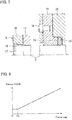
- the axially forward load applied to the object by the outer ring member 4 further increases thereafter, and the axially rearward reaction force which the outer ring member 4 receives from the object exceeds the preload by the elastic member 45, as illustrated in Fig. 7 , the amount by which the elastic member 45 is axially compressed increases, and the carrier 14 moves in the axially rearward direction relative to the rotary shaft 8 within the range of the axial gap 46 between the carrier 14 and the spacer 28.
- the tapered inner peripheral surface 49 and the frictionally coupling surface 47 are uncoupled from each other, thereby allowing the carrier 14 and the rotary shaft 8 to rotate relative to each other.
- the axial gap 46 between the carrier 14 and the spacer 28 is minute such that the distance by which the carrier 14 is movable in the axially rearward direction relative to the rotary shaft 8 is extremely small/short (e.g., 0.5 mm or less).
- the electric linear motion actuator 1 is configured such that the load conversion rate can be switched according to the magnitude of the axial load applied to the object by the outer ring member 4.
- the load sensor 30 can detect the magnitude of the axial load applied to the load sensor 30 based on the output signal from the magnetism detector 34.
- the support member 32 is not deflected by the axially forward load applied to the support member 32 through the snap ring 48. Therefore, even when the magnitude of the axially forward load applied through the snap ring 48 changes, such a change will not affect the reaction force value detected by the load sensor 30. In other words, as illustrated in Fig. 8 , before the axially rearward reaction force which the outer ring member 4 receives from the object exceeds the preload by the elastic member 45, the reaction force value detected by the load sensor 30 does not decrease.
- the load sensor 30 can stably detect the axially rearward reaction force which the outer ring member 4 receives from the object when the outer ring member 4 applies the axially forward load to the object.
- F s in Fig. 8 indicates the magnitude of the preload applied to the carrier 14 from the elastic member 45 while no axially forward load is being applied to the object by the outer ring member 4.
- Figs. 12 and 13 illustrate such an electromechanical brake system.
- This electromechanical brake system includes a brake disk 50 configured to rotate together with a vehicle wheel (not shown); a mounting bracket 51 fixed to the vehicle body so as to be axially unmovable relative to the brake disk 50; a caliper body 52 supported by the mounting bracket 51 so as to be slidable in the axial direction of the brake disk 50 relative to the mounting bracket 51; an inboard brake pad 53 and an outboard brake pad 54 which are opposed to the respective axial sides of the brake disk 50; and the electric linear motion actuator 1, which is arranged to linearly drive the inboard brake pad 53.
- a minute clearance 55 is defined between the inboard brake pad 53 and the brake disk 50.
- the inboard and outboard brake pads 53 and 54 are retained by the mounting bracket 51 so as to be axially movable and circumferentially unmovable.
- the caliper body 52 includes a claw portion 56 axially opposed to the back of the outboard brake pad 54; and an outer shell portion 57 opposed to the radially outer portion of the brake disk 50.
- the outer shell portion 57 of the caliper body 52 is integral with the housing 15 of the electric linear motion actuator 1, but the outer shell portion 57 of the caliper body 52 and the housing 15 of the electric linear motion actuator 1 may be formed separately from each other, and fixedly coupled together, e.g., by bolts.
- the outer ring member 4 is attached to the back side of the inboard brake pad 53 so that the inboard brake pad 53 is movable together with the outer ring member 4 when the outer ring member 4 moves.
- the outer ring member 4 includes, in its end close to the brake disk 50, an engagement recess 59 in which an engagement protrusion 58 formed on the back side of the inboard brake pad 53 is engaged so that the outer ring member 4 is rotationally fixed.
- the outer ring member 4 of the electric linear motion actuator 1 is moved in the axially forward direction to move the inboard brake pad 53 in the axially forward direction. Since, as illustrated in Fig. 6 , the carrier 14 is frictionally coupled to the frictionally coupling surface 47 of the rotary shaft 8 until the inboard brake pad 53 comes into contact with the brake disk 50, the outer ring member 4 illustrated in Fig. 12 axially moves at a relatively high speed until the inboard brake pad 53 comes into contact with the brake disk 50. Therefore, it is possible to bring the inboard brake pad 53 into contact with the brake disk 50 quickly, and thus to improve the response of the brake.
- the electric linear motion actuator 1 in an electromechanical brake system, it is possible to improve the response of the brake, and simultaneously to increase the force with which the inboard brake pad 53 presses the brake disk 50. Also, even while the force with which the inboard brake pad 53 presses the brake disk 50 is small, it is possible to stably control the pressing force of the inboard brake pad 53 based on the output from the load sensor 30.
- Fig. 9 illustrates an electric linear motion actuator 1 according to the second embodiment of the first aspect of the present invention. Elements of the second embodiment corresponding to those of the first embodiment are denoted by the same reference numerals, and their description is omitted.
- This electric linear motion actuator 1 includes a second support member 60 disposed between the support member 32 and the snap ring 48.
- the second support member 60 is a circular annular member through which the rotary shaft 8 extends.
- the radially inner edge of the second support member 60 is supported from its axially rear side by the snap ring 48, and the radially outer edge of the second support member 60 supports the radially outer edge of the support member 32 from its axially rear side.
- the support member 32 and the second support member 60 are in contact with each other only at their radially outer edges, and are out of contact with each other at the portions of the support members 32 and 60 located radially inwardly of their radially outer edges.
- the second support member 60 By providing the second support member 60 between the snap ring 48 and the support member 32, the axially forward load transmitted through the snap ring 48 is applied to the radially outer edge of the support member 32.
- the radially outer edge of the second support member 60 is axially sandwiched between the support protrusion 40 and the snap ring 41.
- the second support member 60 may be integral with the housing 15.
- the electric linear motion actuator 1 is configured such that the axially forward load transmitted through the snap ring 48 is applied to the radially outer edge of the support member 32, the support member 32 is not deflected by this axially forward load. Therefore, even when the magnitude of the axially forward load applied through the snap ring 48 changes due to the axially rearward reaction force which the outer ring member 4 receives from the object, such a change will not affect the reaction force value detected by the load sensor 30. In other words, as illustrated in Fig. 8 , before the axially rearward reaction force which the outer ring member 4 receives from the object exceeds the preload by the elastic member 45, the reaction force value detected by the load sensor 30 does not decrease. Therefore, the load sensor 30 can stably detect the axially rearward reaction force which the outer ring member 4 receives from the object when outer ring member applies the axially forward load to the object.
- Fig. 10 illustrates an electric linear motion actuator 1 according to the third embodiment of the first aspect of the present invention. Elements of the third embodiment corresponding to those of the first embodiment are denoted by the same reference numerals, and their description is omitted.
- the electric linear motion actuator 1 of the third embodiment includes, on the portion of the outer periphery of the rotary shaft 8 between the carrier 14 and the load sensor 30, a snap ring 48 (rear engagement portion) for restricting the range within which the carrier 14 is movable in the axially rearward direction relative to the rotary shaft 8.
- the load sensor 30 is located axially rearward of the snap ring 48.
- a first thrust bearing 27 is mounted between the spacer 28 and the flange member 31 so as to allow the carrier 14 and the load sensor 30 to rotate relative to each other, while transmitting an axial load between the carrier 14 and the load sensor 30.
- a second thrust bearing 61 is mounted between the spacer 28 and the snap ring 48 so as to allow the carrier 14 and the snap ring 48 to rotate relative to each other, while transmitting an axial load between the carrier 14 and the snap ring 48.
- the second thrust bearing 61 may be a sliding bearing. However, by using a rolling bearing as the second thrust bearing 61, it is possible to more effectively reduce the rotational resistance of the carrier 14.
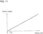
- the load sensor 30 Since, in this embodiment, the load sensor 30 is disposed axially rearward of the snap ring 48, the axially forward load transmitted through the snap ring 48 is not applied to the load sensor 30. Therefore, even when the magnitude of the axially forward load through the snap ring 48 changes, such a change will not affect the reaction force value detected by the load. sensor 30. In other words, as illustrated in Fig. 11 , before the axially rearward reaction force which the outer ring member 4 receives from the object exceeds the preload by the elastic member 45, the reaction force value detected by the load sensor 30 does not decrease. Therefore, the load sensor 30 can stably detect the axially rearward reaction force which the outer ring member 4 receives from the object when the outer ring member 4 applies the axially forward load to the object.
- the load sensor 30 is not located between the frictionally coupling surface 47 (front engagement portion) for restricting the range within which the carrier 14 is movable in the axially forward direction relative to the rotary shaft 8, and the snap ring 48 (rear engagement portion) for restricting the range within which the carrier 14 is movable in the axially rearward direction relative to the rotary shaft 8, the force of the elastic member 45 does not affect the load sensor 30 at all, so that, as illustrated in Fig. 11 , a linear output can be obtained as the output from the load sensor 30.
- the axially front disk 19 and the axially rear disk 20 are annular disks through which the rotary shaft 8 extends.
- a sliding bearing 62 is mounted on the inner periphery of the axially front disk 19, and is in sliding contact with the outer periphery of the rotary shaft 8.
- the outer ring member 4 is axially slidably supported by the inner surface of a receiving hole 26 formed in the housing 15.
- a bearing supporting member 63 is fixedly mounted inside the housing 15 at a position away from the outer ring member 4 in the axially rearward direction.
- the bearing supporting member 63 is a circular annular member through which the rotary shaft 8 extends.
- a radial bearing 39 is mounted on the inner periphery of the bearing supporting member 63 so as to rotatably support the rotary shaft 8.
- the radial bearing 39 may be, for example, a sintered sliding bearing or a deep groove ball bearing.
- the axially rearward movement of the bearing supporting member 63 is restricted by a support protrusion 40 disposed on the inner periphery of the receiving hole 26, whereas the axially forward movement of the bearing supporting member 63 is restricted by a snap ring 41 mounted to the inner periphery of the receiving hole 26.
- the axially forward movement of the rotary shaft 8 relative to the bearing supporting member 63 is restricted by a snap ring 48 mounted on the outer periphery of the rotary shaft 8.
- the axially forward movement of the carrier 14 relative to the rotary shaft 8 is restricted by a snap ring 64 mounted on the outer periphery of the rotary shaft 8 at its axially front end.
- the radial bearing 39 is mounted with its axially forward movement relative to the bearing supporting member 63 restricted.
- the snap ring 48 is disposed axially rearward of the radial bearing 39.
- the snap ring 64 is disposed axially forward of the sliding bearing 62.
- a thrust bearing 27 is mounted between the carrier 14 and the bearing supporting member 63, and rotatably supports the carrier 14 from its axially rear side.
- a spacer 28 is mounted between the carrier 14 and the thrust bearing 27 such that an axial load is transmitted from the carrier 14 to the thrust bearing 27 through the spacer 28.
- An elastic member 45 is mounted between the carrier 14 and the spacer 28, and an axial gap 46 is defined between the carrier 14 and the spacer 28 so as to allow the axial movement of the carrier 14. Due to this, when an axially rearward load is applied to the carrier 14, this load axially compresses the elastic member 45, and moves the carrier 14 in the axially rearward direction relative to the rotary shaft 8 within the range of the axial gap 46 between the carrier 14 and the spacer 28.
- the axial gap 46 between the carrier 14 and the spacer 28 is minute such that the distance by which the carrier 14 is movable in the axially rearward direction relative to the rotary shaft 8 is extremely small/short (e.g., 0.5 mm or
- the elastic member 45 is an annular member through which the rotary shaft 8 extends.
- the elastic member 45 is, for example, a disk spring, but a wave spring or a coil spring may be used instead.
- the elastic member 45 is mounted such that, while no axially rearward load is being applied to the carrier 14 at all, the elastic member 45 is already axially compressed, thereby biasing the carrier 14, and when an axially rearward load is applied to the carrier 14, the amount by which the elastic member 45 is axially compressed increases according to the magnitude of this load.
- a receiving recess 65 is formed in the surface of the spacer 28 opposed to the carrier 14. A portion of the elastic member 45 is received in the receiving recess 65, and the remaining portion of the elastic member 65 is located out of the receiving recess 65.
- the elastic member 45 is mounted between the carrier 14 and the spacer 28, the elastic member 45 may be mounted to another portion of the actuator 1 between the carrier 14 and the bearing supporting member 63, for example, may be mounted between the spacer 28 and the thrust bearing 27, or between the thrust bearing 27 and the bearing supporting member 63.
- the elastic member 45 may be mounted between the two divided members.
- the rotary shaft 8 has, on its outer periphery, a cylindrical surface 12 with which the planetary rollers 13 are in rolling contact; a tapered surface 66 (frictionally coupling portion) located axially rearward of the cylindrical surface 12; and a cylindrical surface 67 connected to the axially rear end of the tapered surface 66.
- the cylindrical surface 67 is supported by the radial bearing 39, and is smaller in diameter than the cylindrical surface 12.
- the tapered surface 66 is a conical surface whose diameter decreases toward the axially rear side thereof at an inclination angle (angle relative to the axial direction) of 5 to 20 degree.
- the axially rear disk 20 of the carrier 14 has, on its inner periphery, a tapered inner peripheral surface 68 opposed to the tapered surface 66 on the outer periphery of the rotary shaft 8.
- the tapered inner peripheral surface 68 has an inclination angle (angle relative to the axial direction) of 5 to 20 degree.
- the tapered inner peripheral surface 68 is preferably equal in inclination angle to the tapered surface 66.
- the tapered inner peripheral surface 68 of the carrier 14 is in contact with the tapered surface 66 on the outer periphery of the rotary shaft 8.
- the tapered inner peripheral surface 68 and the tapered surface 66 are frictionally coupled together by the force of the elastic member 45, so that the relative rotation of the carrier 14 and the rotary shaft 8 is restricted by the frictional force between the surfaces 66 and 68.
- the tapered inner peripheral surface 68 of the carrier 14 is separated from the tapered surface 66 on the outer periphery of the rotary shaft 8.
- the tapered inner peripheral surface 68 and the tapered surface 66 are uncoupled from each other, thereby allowing the carrier 14 and the rotary shaft 8 to rotate relative to each other.
- Fig. 20 illustrates the electromechanical brake system in which the above-described electric linear motion actuator 1 is used. It is described how this electromechanical brake system operates.
- the planetary roller screw type linear motion mechanism 5 is configured such that, while no axially forward load is being applied to the object by the outer ring member 4, the carrier 14 is frictionally coupled to the frictionally coupling portion on the outer periphery of the rotary shaft 8, and thus the relative rotation of the carrier 14 and the rotary shaft 8 is restricted.
- the outer ring member 4 axially moves at a high speed, and the load conversion rate is low.
- the carrier 14 and the frictionally coupling portion on the outer periphery of the rotary shaft 8 are uncoupled from each other, and thus the carrier 14 and the rotary shaft 8 are allowed to rotate relative to each other.
- the planetary roller screw type linear motion mechanism 5 is configured such that the load conversion rate can be switched according to the magnitude of the axial load applied to the object by the outer ring member 4.
- the tapered surface 66 illustrated in Fig. 17 axially forward (i.e., on the left side (in Fig. 17 )) of the cylindrical surface 12, with which the planetary rollers 13 are in rolling contact, and provide the tapered surface 68 on the inner periphery of the axially front disk 19.
- the tapered surface 66 is larger in diameter than the cylindrical surface 12, when the cylindrical surface 12 is finished, e.g., by polishing, it is impossible to use a low-cost machining method (e.g., centerless polishing), thus increasing the machining costs for finishing the cylindrical surface 12 with high accuracy.
- the tapered surface 66 (frictionally coupling portion) on the outer periphery of the rotary shaft 8 is disposed axially rearward of the planetary rollers 13 (i.e., axially rearward of the cylindrical surface 12), the cylindrical surface 12, with which the planetary rollers 13 are in rolling contact, is larger in diameter than any other portion of the rotary shaft 8. Therefore, it is possible to use a low-cost machining method (i.e., a method by which the outer periphery of the rotary shaft 8 is ground with the rotary shaft 8 rollably supported, such as centerless polishing), and to finish the cylindrical surface 12 easily.
- a low-cost machining method i.e., a method by which the outer periphery of the rotary shaft 8 is ground with the rotary shaft 8 rollably supported, such as centerless polishing
- Centerless polishing is a machining method in which, with a workpiece sandwiched between a grinding wheel configured to rotate at a fixed position, and a regulating wheel configured to rotate at a position opposed to the grinding wheel through the workpiece, the outer periphery of the workpiece is continuously polished, while axially feeding the workpiece, with the grinding wheel and the regulating wheel.
- the frictionally coupling portion of the rotary shaft 8 may be, for example, a surface connecting the cylindrical surfaces 12 and 67 together and extending perpendicularly to the axis of the rotary shaft 8.
- the tapered surface 66 is used as the frictionally coupling portion of the rotary shaft 8, when the carrier 14 is frictionally coupled to the rotary shaft 8, it is possible to generate a large frictional force due to the wedge effect of the tapered surface 66.
- the rotary shaft 8 may be, instead, frictionally coupled to a member configured to rotate together with the carrier 14.
- the electric linear motion actuator may be configured such that the elastic member 45 is disposed between the spacer 28 and the thrust bearing 27, the spacer 28 is coupled to the carrier 14 so as to be rotatable together with the carrier 14, and the spacer 28 has the tapered inner peripheral surface 68, which is frictionally coupled to the tapered surface 66 on the outer periphery of the rotary shaft 8.
- a planetary roller screw type linear motion mechanism comprising:
- the planetary roller screw type linear motion mechanism according to additional description 1, wherein the frictionally coupling portion comprises a tapered surface (66) whose diameter decreases toward the one axial direction.
- An electromechanical brake system comprising:
- Electric linear motion actuators 1 according to the first and second embodiments of the third aspect of the present invention are now described with reference to Figs. 21 to 28 .
- Elements of the actuators 1 of the third aspect corresponding to those of the previous embodiments are denoted by the same reference numerals, and their description is omitted.
- the outer ring member 4 is axially slidably supported by the inner surface of a receiving hole 26 formed in the housing 15.
- a bearing supporting member 63 is fixedly mounted inside the housing 15 at a position away from the carrier 14 in the axially rearward direction.
- the bearing supporting member 63 is a circular annular member through which the rotary shaft 8 extends.
- a radial bearing 39 is mounted on the inner periphery of the bearing supporting member 63 so as to rotatably support the rotary shaft 8.
- the radial bearing 39 may be, for example, a sintered sliding bearing or a deep groove ball bearing.
- the axially rearward movement of the bearing supporting member 63 is restricted by a support protrusion 40 disposed on the inner periphery of the receiving hole 26, whereas the axially forward movement of the bearing supporting member 63 is restricted by a snap ring 41 mounted to the inner periphery of the receiving hole 26.
- the axially forward movement of the rotary shaft 8 relative to the bearing supporting member 63 is restricted by a snap ring 48 mounted on the outer periphery of the rotary shaft 8.
- the axially forward movement of the carrier 14 relative to the rotary shaft 8 is restricted by a snap ring 64 mounted on the outer periphery of the rotary shaft 8 at its axially front end.
- the radial bearing 39 is mounted with its axially forward movement relative to the bearing supporting member 63 restricted.
- the snap ring 48 is disposed axially rearward of the radial bearing 39.
- the snap ring 64 is disposed axially forward of the sliding bearing 62, which is on the inner periphery of the axially front disk 19.
- the elastic member 45 is an annular member through which the rotary shaft 8 extends, and is, for example, a disk spring, but a wave spring or a coil spring may be used instead.
- the elastic member 4 is mounted such that, while no axially forward load is being applied to the object by the outer ring member 4 (i.e., while no axially rearward reaction force is being applied to the carrier 14), the elastic member 45 is already axially compressed, so that a preload is applied from the elastic member 45 to the carrier 14.
- a frictionally coupling portion 87 is mounted to the outer periphery of the rotary shaft 8 so as to be axially opposed to the axially front disk 19.
- the frictionally coupling portion 87 is a disk-shaped member formed separately from the rotary shaft 8, and fitted and mounted to the outer periphery of the rotary shaft 8.
- an anti-rotation arrangement 88 is disposed between the fitting surfaces of the frictionally coupling portion 87 and the rotary shaft 8 to prevent the rotation of the frictionally coupling portion 87 relative to the rotary shaft 8.
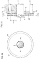
- the anti-rotation arrangement 88 comprises flat surfaces formed by cutting portions of the circumference of the rotary shaft 8 so as to extend parallel to the center axis of the rotary shaft 8. The axially forward movement of the frictionally coupling portion 87 relative to the rotary shaft 8 is restricted by the snap ring 64 on the outer periphery of the rotary shaft 8.
- the frictionally coupling portion 87 has an outer diameter larger than the diameter of the imaginary circle passing through the centers of the planetary rollers 13 (this diameter is hereinafter simply referred to as "the PCD of the planetary rollers 13").
- the carrier 14 is configured to contact the frictionally coupling portion 87 at a contact surface of the frictionally coupling portion 87 which is located radially outwardly of the PCD of the planetary rollers 13, and which has a center at the center of the rotary shaft 8.
- the contact surface of the frictionally coupling portion 87 is a flat surface orthogonal to the axial direction.
- a circular recess 89 is formed in the surface of the frictionally coupling portion 87 opposed to the axially front disk 19 such that the center of the recess 89 coincides with the center of the rotary shaft 8.
- the recess 89 has a diameter larger than the PCD of the planetary rollers 13. Therefore, the carrier 14 comes into contact with the frictionally coupling portion 87 so as to be out of contact with the entire area of the frictionally coupling portion 87 located radially inwardly of the PCD of the planetary rollers 13.
- Fig. 28 illustrates the electromechanical brake system in which the above-described electric linear motion actuator 1 of this embodiment is used. It is described how this electromechanical brake system operates.
- the planetary roller screw type linear motion mechanism 5 is configured such that, while no axially forward load is being applied to the object by the outer ring member 4, the carrier 14 is frictionally coupled to the frictionally coupling portion 87 on the outer periphery of the rotary shaft 8, and thus the relative rotation of the carrier 14 and the rotary shaft 8 is restricted.
- the outer ring member 4 axially moves at a high speed, and the load conversion rate is low.
- the carrier 14 and the frictionally coupling portion 87 on the outer periphery of the rotary shaft 8 are uncoupled from each other, and thus the carrier 14 and the rotary shaft 8 are allowed to rotate relative to each other.
- the planetary roller screw type linear motion mechanism 5 is configured such that the load conversion rate can be switched according to the magnitude of the axial load applied to the object by the outer ring member 4.
- the frictionally coupling portion 87 is formed separately from the rotary shaft 8, it is possible to easily machine both the rotary shaft 8 and the frictionally coupling portion 87, and thus to reduce the total manufacturing cost.
- the frictionally coupling portion 87 is formed such that the carrier 14 comes into contact with the frictionally coupling portion 87 so as to be out of contact with the entire area of the frictionally coupling portion 87 located radially inwardly of the PCD of the planetary rollers 13, it is possible to ensure contact pressure at the area thereof located radially outwardly of the PCD of the planetary rollers 13, and thus to effectively prevent the slippage between the rotary shaft 8 and the carrier 14.
- Fig. 27 shows the second embodiment of the third aspect of the present invention.
- the frictionally coupling portion 87 is mounted to the outer periphery of the rotary shaft 8 so as to be axially opposed to the axially front disk 19. That is, the frictionally coupling portion 87 is a disk-shaped member formed separately from the rotary shaft 8, and fitted and mounted to the outer periphery of the rotary shaft 8.
- the frictionally coupling portion 87 includes a disk portion 90 having an outer diameter larger than the PCD of the planetary rollers 13; and a cylindrical portion 91 extending in the axially rearward direction from the radially outer edge of the disk portion 90, and having, on its inner periphery, a tapered surface 92 opposed to the outer periphery of the axially front disk 19.
- the tapered surface 92 is a tapered inner peripheral surface whose diameter decreases toward the axially front side thereof at an inclination angle (angle relative to the axial direction) of 5 to 20 degree.
- the axially front disk 19 of the carrier 14 has, on its outer periphery, a tapered outer peripheral surface 93 opposed to the tapered surface 92 of the frictionally coupling portion 87, and having an inclination angle (angle relative to the axial direction) of 5 to 20 degree.
- the tapered outer peripheral surface 93 is preferably equal in inclination angle to the tapered surface 92.
- the minimum diameter of the tapered surface 92 on the inner periphery of the cylindrical portion 91 is smaller than the minimum diameter of the tapered outer peripheral surface 93 of the carrier 14. As a result thereof, the carrier 14 comes into contact with the frictionally coupling portion 87 so as to be out of contact with the entire area of the frictionally coupling portion 87 located radially inwardly of the PCD of the planetary rollers 13.
- the planetary roller screw type linear motion mechanism 5 of this embodiment is configured such that, as illustrated in Fig. 27 , when the carrier 14 is frictionally coupled to the frictionally coupling portion 87, the carrier (14) comes into contact with an area of the frictionally coupling portion 87 located radially outwardly of the PCD of the planetary rollers 13, and having a center at the center of the rotary shaft 8, the contact areas of the frictionally coupling portion 87 and the carrier 14 are large in radius, so that large torque is transmittable with the carrier 14 and the frictionally coupling portion 87 frictionally coupled together. Therefore, even when the rotary shaft 8 accelerates or decelerates rapidly, it is possible to prevent the slippage between the rotary shaft 8 and the carrier 14, thus enabling the linear motion mechanism 5 to operate in a reliable manner.
- the contact surface of the frictionally coupling portion 87 with which the carrier 14 comes into contact comprises a tapered surface 92 whose center coincides with the center of the rotary shaft 8 and whose diameter is larger than the PCD of the planetary rollers 13, the contact surface pressure between the frictionally coupling portion 87 and the carrier 14 is high due to the wedge action/effect of the tapered surface 92, thereby making it possible to more effectively prevent the slippage between the rotary shaft 8 and the carrier 14.
- the frictionally coupling portion 87 is formed such that the carrier 14 comes into contact with the frictionally coupling portion 87 so as to be out of contact with the entire area of the frictionally coupling portion 87 located radially inwardly of the PCD of the planetary rollers 13, it is possible to ensure contact pressure at an area thereof located radially outwardly of the PCD of the planetary rollers 13, and thus to effectively prevent the slippage between the rotary shaft 8 and the carrier 14.
- a planetary roller screw type linear motion mechanism comprising:
- the planetary roller screw type linear motion mechanism according to additional description 4, wherein the carrier (14) includes:
- the planetary roller screw type linear motion mechanism according to any of additional descriptions 4 to 6, wherein the contact surface of the frictionally coupling portion (87) with which the carrier (14) comes into contact comprises a tapered surface (92) whose center coincides with the center of the rotary shaft (8), and whose diameter is larger than the diameter (PCD) of the imaginary circle passing through the centers of the planetary rollers (13).
- An electromechanical brake system comprising:
- Electric linear motion actuators 1 according to the first to seventh embodiments of the fourth aspect of the present invention are now described with reference to Figs. 29 to 43 .
- Elements of the fourth aspect corresponding to those of the previous embodiments are denoted by the same reference numerals, and their description is omitted.
- the axially rearward movement of the bearing supporting member 63 is restricted by a support protrusion 40 disposed on the inner periphery of the receiving hole 26, whereas the axially forward movement of the bearing supporting member 63 is restricted by a snap ring 41 mounted to the inner periphery of the receiving hole 26.
- the axially forward movement of the rotary shaft 8 relative to the bearing supporting member 63 is restricted by a snap ring 48 mounted on the outer periphery of the rotary shaft 8.
- the axially forward movement of the carrier 14 relative to the rotary shaft 8 is restricted by a frictionally coupling portion 87 fixed to the outer periphery of the rotary shaft 8 at its axially front end.
- the frictionally coupling portion 87 is an annular member formed separately from the portion of the rotary shaft 8 having a cylindrical surface 12, and is fixedly fitted to the outer periphery of a fitting shaft portion 8a formed on the axially front end of the rotary shaft 8.
- the fitting shaft portion 8a has no portion that radially outwardly protrudes beyond the cylindrical surface 12.
- the frictionally coupling portion 87 has an outer diameter larger than the diameter of the cylindrical surface 12 (that is, the frictionally coupling portion 87 has a portion that radially outwardly protrudes beyond the cylindrical surface 12).
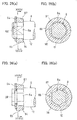
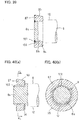
- the rotation of the frictionally coupling portion 87 relative to the rotary shaft 8 is restricted by fitting the frictionally coupling portion 87 to an anti-rotation arrangement 88 formed on the outer periphery of the fitting shaft portion 8a of the rotary shaft 8 and having a non-circular cross section.
- the anti-rotation arrangement 88 comprise flat surfaces formed by cutting portions of the circumference of the rotary shaft 8 so as to extend parallel to the center axis of the rotary shaft 8.
- the axially forward movement of the frictionally coupling portion 87 relative to the rotary shaft 8 is restricted by a snap ring 64 mounted on the outer periphery of the fitting shaft portion 8a of the rotary shaft 8, whereas the axially rearward movement of the frictionally coupling portion 87 relative to the rotary shaft 8 is restricted by a step 94 defined at the axially rear end of the fitting shaft portion 8a.
- the step 94 has an axially rearwardly increasing diameter.
- the frictionally coupling portion 87 has, on its outer periphery, a tapered surface 95 whose diameter decreases toward the axially rear side thereof at an inclination angle (relative to the axial direction) of 5 to 20 degree.
- the axially front disk 19 of the carrier 14 has, on its inner periphery, a tapered inner peripheral surface 96 opposed to the tapered surface 95 of the frictionally coupling portion 87, and having an inclination angle (relative to the axial direction) of 5 to 20 degree.
- the tapered inner peripheral surface 96 is preferably equal in inclination angle to the tapered surface 95.
- the tapered inner peripheral surface 96 of the carrier 14 is in contact with the tapered surface 95 on the outer periphery of the frictionally coupling portion 87.
- the tapered inner peripheral surface 96 and the tapered surface 95 are frictionally coupled together by the force of the elastic member 45, so that the relative rotation of the carrier 14 and the rotary shaft 8 is restricted by the frictional force between the surfaces 96 and 95.
- Fig. 43 illustrates the electromechanical brake system in which the above-described electric linear motion actuator 1 is used. It is described how this electromechanical brake system operates.
- the carrier 14 is frictionally coupled to the frictionally coupling portion 87, and thus the relative rotation of the carrier 14 and the rotary shaft 8 is restricted, so that, in this state, the outer ring member 4 axially moves at a high speed, and the load conversion rate is low.
- the carrier 14 and the frictionally coupling portion 87 are uncoupled from each other, and thus the carrier 14 and the rotary shaft 8 are allowed to rotate relative to each other, so that, in this state, the outer ring member 4 axially moves at a low speed, and the load conversion rate is high.
- the planetary roller screw type linear motion mechanism 5 is configured such that the load conversion rate can be switched according to the magnitude of the axial load applied to the object by the outer ring member 4.
- the frictionally coupling portion 87 illustrated in Fig. 30 may be formed integral with the portion of the rotary shaft 8 having the cylindrical surface 12, if the frictionally coupling portion 87 is integral with the rotary shaft 8, since the tapered surface 95 is larger in diameter than the cylindrical surface 12, when the cylindrical surface 12 is finished, e.g., by polishing, it is impossible to use a low-cost machining method (e.g., centerless polishing), thus increasing the machining costs for finishing the cylindrical surface 12 with high accuracy.
- a low-cost machining method e.g., centerless polishing
- the frictionally coupling portion 87 is an annular member formed separately from the portion of the rotary shaft 8 having the cylindrical surface 12, the cylindrical surface 12, with which the planetary rollers 13 are in rolling contact, is larger in diameter than any other portion of the rotary shaft 8. Therefore, it is possible to use a low-cost machining method, i.e., a method by which the outer periphery of the rotary shaft 8 is machined with the rotary shaft 8 rollably supported (e.g., centerless polishing), and to easily finish the cylindrical surface 12, e.g., by polishing.
- Centerless polishing is a machining method in which, with a workpiece sandwiched between a grinding wheel configured to rotate at a fixed position, and a regulating wheel configured to rotate at the position opposed to the grinding stone through the workpiece, the outer periphery of the workpiece is continuously polished, while axially feeding the workpiece, with the grinding wheel and the regulating wheel.
- the rotation of the frictionally coupling portion 87 relative to the rotary shaft 8 is restricted by fitting the frictionally coupling portion 87 to the anti-rotation arrangement 88 disposed on the outer periphery of the fitting shaft portion 8a of the rotary shaft 8, and having a non-circular cross section, and the axial movement of the frictionally coupling portion 87 relative to the rotary shaft 8 is restricted by the snap ring 64 on the outer periphery of the rotary shaft 8, it is possible to easily mount the frictionally coupling portion 87 to the outer periphery of the rotary shaft 8.
- the anti-rotation arrangement 88 having a non-circular cross section comprises a plurality of (two in Fig. 32 ) flat surfaces formed by cutting portions of the circumference of the rotary shaft 8 so as to extend parallel to the center axis of the rotary shaft 8 and so as to be circumferentially equidistantly spaced apart from each other, it is possible to more accurately position the center of the frictionally coupling portion 87 on the center of the rotary shaft 8.
- the anti-rotation arrangement 88 may comprise only one such flat surface as illustrated in Figs. 35 (a) and (b) .
- Figs. 36(a) and 36(b) illustrate the second embodiment of the fourth aspect of the present invention.
- the rotation of the frictionally coupling portion 87 relative to the rotary shaft 8 is restricted by fitting the frictionally coupling portion 87 to an anti-rotation arrangement 88 disposed on the outer periphery of the fitting shaft portion 8a of the rotary shaft 8 and having a non-circular cross section.
- the anti-rotation arrangement has a polygonal cross section.
- Figs. 37(a) and 37(b) illustrate the third embodiment of the fourth aspect of the present invention.
- the rotation of the frictionally coupling portion 87 relative to the rotary shaft 8 is restricted by fitting the frictionally coupling portion 87 to an anti-rotation arrangement 88 disposed on the outer periphery of the fitting shaft portion 8a of the rotary shaft 8 and having a non-circular cross section.
- the anti-rotation arrangement 88 of this embodiment comprises splines (a plurality of circumferentially equidistantly spaced apart, axially extending protrusions).
- Fig. 38 illustrates the fourth embodiment of the fourth aspect of the present invention.
- the frictionally coupling portion 87 is fitted on the outer periphery of the fitting shaft portion 8a of the rotary shaft 8 with interference.
- the frictionally coupling portion 87 has a cylindrical surface 97 on its inner periphery
- the fitting shaft portion 8a also has a cylindrical surface 98 on its outer periphery.
- the cylindrical surface 97 on the inner periphery of the frictionally coupling portion 87 is smaller in diameter than the cylindrical surface 98 on the outer periphery of the fitting shaft portion 8a.
- Fig. 39 illustrates the fifth embodiment of the fourth aspect of the present invention.
- the frictionally coupling portion 87 is welded to the outer periphery of the fitting shaft portion 8a of the rotary shaft 8.
- the frictionally coupling portion 87 has a cylindrical surface 99 on its inner periphery
- the fitting shaft portion 8a also has a cylindrical surface 100 on its outer periphery.
- the cylindrical surface 99 on the inner periphery of the frictionally coupling portion 87 is slightly larger in diameter than the cylindrical surface 100 on the outer periphery of the fitting shaft portion 8a.
- the base materials of the frictionally coupling portion 87 and the rotary shaft 8 are partially melted and integrated into beads 101 at the axially front ends of the portions of the cylindrical surfaces 99 and 100 fitted to each other.
- Figs. 40(a) and 40(b) illustrate the sixth embodiment of the fourth aspect of the present invention.
- the fitting shaft portion 8a of the rotary shaft 8 includes, on its outer periphery, splines 102 higher in hardness than the inner peripheral portion of the frictionally coupling portion 87. By wedging the splines 102 against the inner peripheral portion of the frictionally coupling portion 87, the frictionally coupling portion 87 is fixed to the rotary shaft 8.
- the frictionally coupling portion 87 is fixed to the fitting shaft portion 8a.
- the splines 102 are formed on the outer periphery of the fitting shaft portion 8a of the rotary shaft 8.
- the outer periphery of the fitting shaft portion 8a is hardened by heat treatment.
- the inner peripheral portion of the frictionally coupling portion 87 comprises a cylindrical surface 103 which is not subjected to heat treatment. Therefore, the splines 102 are higher in hardness than the inner peripheral portion of the frictionally coupling portion 87.
- the circumcircle of the splines 102 is larger in diameter than the cylindrical surface 103.
- Fig. 42 illustrates a fixing method for fixing the frictionally coupling portion 87 to the fitting shaft portion 8a in the actuator 1 according to the seventh embodiment of the fourth group of the present invention.
- splines 104 are formed on the inner periphery of the frictionally coupling portion 87.
- the inner periphery of the frictionally coupling portion 87 is hardened by heat treatment.
- the outer peripheral portion of the fitting shaft portion 8a of the rotary shaft 8 comprises a cylindrical surface 105 which is not subjected to heat treatment. Therefore, the splines 104 of the frictionally coupling portion 87 are higher in hardness than the outer peripheral portion of the fitting shaft portion 8a of the rotary shaft 8.
- the inscribed circle of the splines 104 is smaller in diameter than the cylindrical surface 105.
- the splines 104 are wedged against the cylindrical surface 105 on the outer periphery of the fitting shaft portion 8a, thereby plastically deforming the outer peripheral portion of the fitting shaft portion 8a. Due to this plastic deformation, the frictionally coupling portion 87 is firmly fixed to the fitting shaft portion 8a.
- a planetary roller screw type linear motion mechanism comprising:
- the planetary roller screw type linear motion mechanism according to additional description 9, further comprising:
- the planetary roller screw type linear motion mechanism according to additional description 9, wherein the rotary shaft (8) includes, on its outer periphery, splines (102) higher in hardness than the inner peripheral portion of the frictionally coupling portion (87), and wedged against the inner peripheral portion of the frictionally coupling portion (87) so that the frictionally coupling portion (87) is fixed to the rotary shaft (8).
- the planetary roller screw type linear motion mechanism according to additional description 9, wherein the frictionally coupling portion (87) includes, on its inner periphery, splines (104) higher in hardness than the outer peripheral portion of the rotary shaft (8) fitted to the frictionally coupling portion (87), and wedged against the outer peripheral portion of the rotary shaft (8) so that the frictionally coupling portion (87) is fixed to the rotary shaft (8).
- the planetary roller screw type linear motion mechanism according to any of additional descriptions 9 to 14, wherein the contact surface of the frictionally coupling portion (87) with which the carrier (14) comes into contact comprises a tapered surface whose diameter decreases toward the axially rearward side thereof.
- An electromechanical brake system comprising:
Landscapes
- Engineering & Computer Science (AREA)
- General Engineering & Computer Science (AREA)
- Mechanical Engineering (AREA)
- Transportation (AREA)
- Braking Arrangements (AREA)
- Transmission Devices (AREA)
Abstract
Description
- The present invention relates to an electric linear motion actuator, and an electromechanical brake system in which the electric linear motion actuator is used.
- As brake systems for vehicle, hydraulic brake systems driven by oil pressure have been widely used. However, since hydraulic brake systems use brake oil, a burden on the environment is high. Also, it is difficult to add, to hydraulic brake systems, sophisticated functions such as an anti-lock brake control function, a stability control function, and a brake assisting function. In order to further increase the functionality of brake systems, and reduce the burden on the environment, electromechanical brake systems, which are driven by an electric motor, are gathering attention.
- Electromechanical brake systems include a brake disk that rotate together with a vehicle wheel; a brake pad opposed to the brake disk; and an electric linear motion actuator for linearly driving the brake pad to press the brake pad against the brake disk, thereby generating a braking force.
- For example, the below-identified
Patent document 1 discloses an electric linear motion actuator used in such electromechanical brake systems, and including an electric motor; a rotary shaft to which the rotation of the electric motor is transmitted; a plurality of planetary rollers kept in rolling contact with the outer periphery of the rotary shaft; a carrier retaining the planetary rollers such that the planetary rollers can revolve around the rotary shaft while rotating about their respective center axes; an outer ring member surrounding the planetary rollers; and a housing in which the outer ring member is axially movably received. The outer ring has a helical rib on the inner periphery. Each planetary roller has, in the outer periphery, a helical groove or circumferential grooves in which the helical rib is engaged. - For this electric linear motion actuator, when the electric motor is rotated, the rotation of the rotary shaft is transmitted to the planetary rollers kept in rolling contact with the outer periphery of the rotary shaft, and thus the planetary rollers revolve around the rotary shaft while rotating about their respective center axis. As a result thereof, since the helical rib on the inner periphery of the outer ring member is engaged in the helical grooves or the circumferential grooves in the outer peripheries of the planetary rollers, the outer ring member axially moves.
- When this electric linear motion actuator is used in an electromechanical brake system, if the helical rib on the inner periphery of the outer ring member has a large lead angle, since the outer ring member axially moves at a high speed, it is possible to bring the brake pad into contact with the brake disk quickly in order to generate the braking force, and thus to improve the response of the brake. However, since the load conversion rate is low, the force with which the brake pad presses the brake disk is small.
- On the other hand, if the helical rib on the inner periphery of the outer ring member has a small lead angle, since the load conversion rate is high, it is possible to press the brake pad against the brake disk with a large force when applying the brake. However, since the outer ring member axially moves at a low speed, it is impossible to bring the brake pad into contact with the brake disk quickly, that is, the response of the brake is slow. Namely, in this conventional arrangement, improving the response of the brake is in conflict with increasing the force with which the brake pad presses the brake disk.
- In order to improve the response of the brake, and simultaneously increase the force with which the brake pad presses the brake disk, the below-identified
Patent document 1 proposes a structure which enables the load conversion rate to be switched according to the magnitude of the axial load applied to an object by the outer ring member. - Namely, in
Patent Document 1, an elastic member supports the carrier such that, due to the axially rearward reaction force which the outer ring member receives when the outer ring member applies an axially forward load to the object, the carrier moves in the axially rearward direction relative to the rotary shaft. Also, a frictionally coupling portion is disposed on the outer periphery of the rotary shaft such that, while the carrier has not moved in the axially rearward direction relative to the rotary shaft, the carrier and the frictionally coupling portion are frictionally coupled together so as to restrict the relative rotation of the carrier and the rotary shaft, and such that, when the carrier has moved in the axially rearward direction relative to the rotary shaft, the carrier and the frictionally coupling portion are uncoupled from each other so as to allow the carrier and the rotary shaft to rotate relative to each other. - With this arrangement, while no axially forward load is being applied to the object by the outer ring member, the carrier and the frictionally coupling portion on the outer periphery of the rotary shaft are frictionally coupled together, thereby restricting the relative rotation of the carrier and the rotary shaft. Therefore, in this state, the rotation of the rotary shaft transmitted from outside causes the carrier to rotate together with the rotary shaft, so that the outer ring member axially moves at a low reduction ratio. On the other hand, when the axially forward load is applied to the object by the outer ring member, the carrier and the frictionally coupling portion on the outer periphery of the rotary shaft are uncoupled from each other, thereby allowing the carrier and the rotary shaft to rotate relative to each other. Therefore, the rotation of the rotary shaft transmitted from outside causes the planetary rollers to revolve around the rotary shaft while rotating about their respective center axes, and thus the outer ring member axially moves at a high reduction ratio. In this way, it is possible to switch the load conversion rate (reduction ratio) according to the magnitude of the axial load applied to the object by the outer ring member.
- On the other hand, the below-identified
Patent document 2 discloses a load sensor used in an electromechanical brake system, and configured to detect the magnitude of the axially rearward reaction force which the electric linear motion actuator of the brake system receives when it presses the brake pad against the brake disk. This load sensor is disposed to support, through the planetary rollers and the carrier, the axially rearward reaction force which the outer ring member receives from the object when the outer ring member applies an axially forward load to the object. -
- Patent document 1: Japanese Patent No.
5496836 - Patent document 2: Japanese Unexamined Patent Application Publication No.
2014-016307 - The inventor of the present application experimentally prepared, in his company, an electric
linear motion actuator 77 including, as illustrated inFig. 14 , a planetary roller screw typelinear motion actuator 74 configured to axially move anouter ring 72 due to the engagement of ahelical rib 73 on the inner periphery of theouter ring member 72 incircumferential grooves 71 in the outer peripheries of theplanetary rollers 70; and aload sensor 76 configured to support, through theplanetary rollers 70 and acarrier 75, the axially rearward reaction force which theouter ring member 72 receives from an object when the outer ring member applies the axially forward load to the object. Then, the inventor conducted an experiment to find the relationship between the magnitude of the axially forward load applied to the object from theouter ring member 72, and the output from theload sensor 76. - The electric
linear motion actuator 77 used in the above experiment includes (though some of the below elements are already mentioned above) arotary shaft 78 to which the rotation of an electric motor (not shown) is transmitted; pluralplanetary rollers 70 in rolling contact with the outer periphery of therotary shaft 78; acarrier 75 which retains theplanetary rollers 70 such that theplanetary rollers 70 can revolve around therotary shaft 78 while rotating about their respective center axes; anouter ring member 72 surroundings theplanetary rollers 70; ahousing 79 in which theouter ring member 72 is axially movably received; ahelical rib 73 on the inner periphery of theouter ring member 72; andcircumferential grooves 71 in the outer peripheries of theplanetary rollers 70. - The
rotary shaft 78 is provided, on its outer periphery, with an frictionallyengaging surface 80 configured to restrict the range within which thecarrier 75 is movable in the axially forward direction relative to therotary shaft 78; and asnap ring 81 configured to restrict the range within which thecarrier 75 is movable in the axially rearward direction relative to therotary shaft 78. Anelastic member 82 is mounted between thecarrier 75 and theload sensor 76 so as to bias thecarrier 75 in the axially forward direction relative to therotary shaft 78. - The frictionally
engaging surface 80 comprises a tapered surface configured such that, while thecarrier 75 has not moved in the axially rearward direction relative to therotary shaft 78, the tapered surface and thecarrier 75 are frictionally coupled together so as to restrict the relative rotation of thecarrier 75 and therotary shaft 78, and such that, when thecarrier 75 has moved in the axially rearward direction relative to therotary shaft 78, the tapered surface and thecarrier 75 are uncoupled from each other so as to allow thecarrier 75 and therotary shaft 78 to rotate relative to each other. - The
load sensor 76 is fixedly mounted at a position axially rearward of thecarrier 75. Theload sensor 76 includes aflange member 83 configured to support the axially rearward reaction force which theouter ring member 72 receives when theouter ring member 72 applies the axially forward load to the object such that theflange member 83 is deflected by the axially rearward reaction force; a circularannular support member 84 disposed axially rearward of theflange member 83; amagnetic target 85 configured to generate a magnetic field; and amagnetism detector 86 configured to detect the magnetic field generated by themagnetic target 85. Theload sensor 76 is configured such that, as theflange member 83 is deflected, themagnetic target 85 and themagnetism detector 86 are displaced from each other according to the degree of such deflection, and is capable of detecting the magnitude of the reaction force based on the magnetic field which themagnetism detector 86 detects. - By the experiment conducted to find the relationship between the magnitude of the axially forward load applied to the object from the
outer ring member 72, and the output from theload sensor 76, the below-described problem was discovered. - Namely, it is expected that, as the magnitude of the axially forward load applied to the object from the
outer ring member 72 is monotonically increased, the reaction force value detected by theload sensor 76 also monotonically increases according to the magnitude of this load. - Actually, however, it turned out that, when the magnitude of the axially forward load applied to the object from the
outer ring member 72 was monotonically increased, as illustrated inFig. 15 , the reaction force value detected by theload sensor 76 decreased temporarily, and then increased. - It is considered that the reaction force value detected by the
load sensor 76 decreased temporarily for the following reasons. - Assuming that: FOR is the magnitude of the axially rearward reaction force which the
outer ring member 72 receives when theouter ring member 72 applies an axially forward load to the object; Fc is the magnitude of the axial load applied to theload sensor 76 from thecarrier 75; FSR is the magnitude of the axially forward load applied to theload sensor 76 through thesnap ring 81; FH is the magnitude of the axial load which thesupport member 84 receives from thehousing 79; and Fs is the magnitude of the preload applied to thecarrier 75 by theelastic member 82 while no axially forward load is being applied to the object by theouter ring member 72, then the relations FC = FS, FSR = FS - FOR, and FH = FOR are satisfied while FOR ≤ FS; and the relations FC = FOR, FSR = 0, and FH = FOR are met while FOR > FS. - The reason why FSR = FS - FOR while FOR ≤ FS is because, when the axially rearward reaction force FOR is applied to the
outer ring member 72 from the object, the axial load applied to the frictionallyengaging surface 80 from thecarrier 75 decreases by the amount equal to the reaction force FOR, so that the axially forward load FSR applied through thesnap ring 81 also decreases. Also, the load FSR elastically deforms thesupport member 84 of theload sensor 76 in the axially forward direction. - This led to the discovery that, not only because load FSR that deflects the
support member 84 of theload sensor 76 in the axially forward direction is actually applied to thesupport member 84, but because the load FsR changes according to the magnitude of For, when the magnitude of the axially forward load applied to the object from theouter ring member 72 monotonically increases, the reaction force value detected by theload sensor 76 decreases temporarily as illustrated inFig. 15 . - If, as illustrated in
Fig. 15 , the reaction force value detected by theload sensor 76 decreases temporarily, since the value detected by theload sensor 76 is not in a one-to-one relationship with the magnitude of the actual reaction force anymore, it is impossible to stably control the magnitude of the axial load based on the value detected by theload sensor 76. - An object of the present invention is, in an electric linear motion actuator including a carrier axially movably supported by the elastic member, to enable the load sensor to stably detect the axially rearward reaction force which the outer ring member receives from the object when the outer ring member applies the axially forward load to the object.
- In order to achieve the above object, the present invention provides an electric linear motion actuator comprising: an electric motor; a rotary shaft to which rotation of the electric motor is to be transmitted; a plurality of planetary rollers in rolling contact with an outer periphery of the rotary shaft, and each having an outer periphery; a carrier retaining the planetary rollers such that the planetary rollers can revolve around the rotary shaft while rotating about respective center axes of the planetary rollers; an outer ring member surrounding the planetary rollers, and supported so as to be axially movable; a housing in which the outer ring member is axially movably received; a helical rib disposed on an inner periphery of the outer ring member; either helical grooves each disposed in the outer periphery of a respective one of the planetary rollers, or circumferential grooves, a plurality of the circumferential grooves being disposed in the outer periphery of a respective one of the planetary rollers, wherein the helical rib is engaged in the helical grooves or the circumferential grooves such that the outer ring member is axially movable when the planetary rollers revolve around the rotary shaft while rotating about the respective center axes thereof, a front engagement portion disposed on the outer periphery of the rotary shaft so as to restrict a range within which the carrier is movable in an axially forward direction relative to the rotary shaft; a rear engagement portion disposed on the outer periphery of the rotary shaft so as to restrict a range within which the carrier is movable in an axially rearward direction relative to the rotary shaft; and an elastic member configured to bias the carrier in the axially forward direction relative to the rotary shaft; wherein the electric linear motion actuator is configured such that:while a first axially forward load is not being applied to an object by the outer ring member, a preload is applied to the front engagement portion by the elastic member, and when the first axially forward load is applied to the object by the outer ring member, an axial load applied to the front engagement portion decreases by an amount equal to an axially rearward reaction force which the outer ring member receives from the object when the first axially forward load is applied to the object by the outer ring member, characterized in that the electric linear motion actuator further comprises a load sensor configured to support, through the planetary rollers and the carrier, the axially rearward reaction force, wherein the load sensor is disposed such that any change in magnitude of a second axially forward load applied through the rear engagement portion does not affect a value of the axially rearward reaction force detected by the load sensor.
- With this arrangement, since, even when the magnitude of the axially forward load applied from the rear engagement portion changes, the reaction force value detected by the load sensor is not affected, the load sensor can stably detect the axially rearward reaction force which the outer ring member receives form the object when the outer ring member applies an axially forward load to the object.
- The above electric linear motion actuator may be an actuator wherein the load sensor comprises: a flange member configured to be deflected by the axially rearward reaction force; a circular annular plate-shaped support member disposed axially rearward of the flange member; a magnetic target configured to generate a magnetic field; and a magnetism detector configured to detect the magnetic field generated by the magnetic target, wherein one of the magnetic target and the magnetism detector is fixed to the flange member, and the other of the magnetic target and the magnetism detector is fixed to the circular annular plate-shaped support member such that, as the flange member is deflected, the magnetic target and the magnetism detector are displaced from each other according to a degree of deflection of the flange member, wherein the circular annular plate-shaped support member is disposed between the carrier and the rear engagement portion such that the second axially forward load is applied to the circular annular plate-shaped support member, and wherein the circular annular plate-shaped support member includes, on an axial side surface of the circular annular plate-shaped support member, a plurality of radially extending ribs circumferentially spaced apart from each other, and configured such that, due to the ribs, even when the magnitude of the axially forward load applied from the rear engagement portion changes, the reaction force value detected by the load sensor is not affected.
- With this arrangement, since the ribs on the axial side surface of the support member increase the rigidity of the support member, the support member is not deflected by the axially forward load input to the support member. Therefore, even when the magnitude of the axially forward load applied from the rear engagement portion changes, the reaction force value detected by the load sensor is not affected.
- Also, the above electric linear motion actuator may be an actuator wherein the load sensor comprises: a flange member configured to be deflected by the axially rearward reaction force; a circular annular plate-shaped support member disposed axially rearward of the flange member; a magnetic target configured to generate a magnetic field; and a magnetism detector configured to detect the magnetic field generated by the magnetic target, wherein one of the magnetic target and the magnetism detector is fixed to the flange member, and the other of the magnetic target and the magnetism detector is fixed to the circular annular plate-shaped support member such that, as the flange member is deflected, the magnetic target and the magnetism detector are displaced from each other according to a degree of deflection of the flange member, wherein the circular annular plate-shaped support member has a radially outer edge, and is disposed between the carrier and the rear engagement portion such that the second axially forward load is applied to the radially outer edge of the circular annular plate-shaped support member such that, even when the magnitude of the axially forward load applied from the rear engagement portion changes, the reaction force value detected by the load sensor is not affected.
- With this arrangement, since an axially forward load is input to the radially outer edge of the support member, the support member is not deflected by the axially forward load input to the support member. Therefore, even when the magnitude of the axially forward load applied from the rear engagement portion changes, the reaction force value detected by the load sensor is not affected.
- The load sensor may be disposed axially rearward of the rear engagement portion such that, even when the magnitude of the axially forward load applied from the rear engagement portion changes, the reaction force value detected by the load sensor is not affected.
- With this arrangement, since the load sensor is disposed axially rearward of the rear engagement portion, the axially forward load applied from the rear engagement portion is not input to the load sensor. Therefore, even when the magnitude of the axially forward load applied from the rear engagement portion changes, the reaction force value detected by the load sensor is not affected.
- The electric linear motion actuator may further comprise: a first thrust bearing arranged to allow the carrier and the load sensor to rotate relative to each other, while transmitting any axial load between the carrier and the load sensor; and a second thrust bearing arranged to allow the carrier and the rear engagement portion to rotate relative to each other, while transmitting any axial load between the carrier and the rear engagement portion.
- With this arrangement, it is possible to stably detect a reaction force with the load sensor, while effectively reducing the rotational resistance of the carrier.
- The front engagement portion may comprise a frictionally coupling surface configured such that, while the carrier has not moved in the axially rearward direction relative to the rotary shaft, the frictionally coupling surface and the carrier are frictionally coupled together so as to restrict a relative rotation of the carrier and the rotary shaft, and such that, when the carrier has moved in the axially rearward direction relative to the rotary shaft, the frictionally coupling surface and the carrier are uncoupled from each other so as to allow the carrier and the rotary shaft to rotate relative to each other.
- The present invention also provides an electromechanical brake system comprising: a brake disk configured to rotate together with a vehicle wheel; a brake pad opposed to the brake disk; and the above-described electric linear motion actuator, which is configured to linearly drive the brake pad.
- For the electric linear motion actuator of the present invention, since, even when the magnitude of the axially forward load applied from the rear engagement portion changes, the reaction force value detected by the load sensor is not affected, the load sensor can stably detect the axially rearward reaction force which the outer ring member receives form the object when the outer ring member applies an axially forward load to the object.
-
-
Fig. 1 is a sectional view of an electric linear motion actuator according to a first embodiment of a first aspect of the present invention. -
Fig. 2 is an enlarged sectional view illustrating a planetary roller screw type linear motion mechanism ofFig. 1 and its vicinity. -
Fig. 3 is a sectional view taken along line III-III ofFig. 2 . -
Fig. 4 is an enlarged sectional view illustrating a load sensor ofFig. 2 and its vicinity. -
Fig. 5 is a sectional view taken along line V-V ofFig. 4 . -
Fig. 6 is a view illustrating the state in which no axially rearward load is being applied to a carrier ofFig. 2 , and thus a tapered inner peripheral surface of the carrier and a frictionally coupling surface of a rotary shaft are frictionally coupled together. -
Fig. 7 is a view illustrating the state in which an axially rearward load is being applied to the carrier ofFig. 2 , and thus the tapered inner peripheral surface of the carrier and the frictionally coupling surface of the rotary shaft are uncoupled from each other. -
Fig. 8 is a graph illustrating the relationship between the magnitude of the axially forward load applied to an object from an outer ring member, and the output from the load sensor in the electric linear motion actuator according to each of the first and second embodiments of the first aspect of the present invention. -
Fig. 9 is an enlarged sectional view illustrating the load sensor of the electric linear motion actuator according to the second embodiment of the first aspect of the present invention, and the vicinity of the load sensor. -
Fig. 10 is an enlarged sectional view illustrating a load sensor of an electric linear motion actuator according to a third embodiment of the first aspect of the present invention, and the vicinity of the load sensor. -
Fig. 11 is a graph illustrating the relationship between the magnitude of the axially forward load applied to the object from an outer ring member, and the output from the load sensor in the electric linear motion actuator according to the third embodiment of the first aspect of the present invention. -
Fig. 12 is a sectional view of an electromechanical brake system in which the electric linear motion actuator ofFig. 1 is used. -
Fig. 13 is a view of the electromechanical brake system ofFig. 12 , when seen from the inboard side. -
Fig. 14 is a sectional view of an electric linear motion actuator illustrated as a comparative example. -
Fig. 15 is a graph illustrating the relationship between the magnitude of the axially forward load applied to the object from the outer ring member, and the output from the load sensor in the electric linear motion actuator ofFig. 14 . -
Fig. 16 is a sectional view of an electric linear motion actuator including a planetary roller screw type linear motion mechanism embodying a second aspect of the present invention. -
Fig. 17 is an enlarged sectional view illustrating the planetary roller screw type linear motion mechanism ofFig. 16 and its vicinity. -
Fig. 18 is an enlarged sectional view illustrating an elastic member ofFig. 17 and its vicinity. -
Fig. 19 is a view illustrating the state in which an axially rearward reaction force is applied to a carrier ofFig. 18 . -
Fig. 20 is a sectional view of an electromechanical brake system in which the electric linear motion actuator ofFig. 16 is used. -
Fig. 21 is a sectional view of an electric linear motion actuator including a planetary roller screw type linear motion mechanism according to a first embodiment of a third aspect of the present invention. -
Fig. 22 is an enlarged sectional view illustrating the planetary roller screw type linear motion mechanism ofFig. 21 and its vicinity. -
Fig. 23 is an enlarged sectional view illustrating a frictionally coupling portion ofFig. 22 and its vicinity. -
Fig. 24 is a sectional view taken along line XXIV-XXIV ofFig. 23 . -
Fig. 25 is a view illustrating the state in which no axially rearward load is being applied to a carrier ofFig. 22 , and thus the carrier and the frictionally coupling portion are frictionally coupled together. -
Fig. 26 is a view illustrating the state in which an axially rearward load is applied to the carrier ofFig. 22 , and thus the carrier and the frictionally coupling portion are uncoupled from each other. -
Fig. 27 is an enlarged sectional view illustrating a frictionally coupling portion of a planetary roller screw type linear motion mechanism according to a second embodiment of the third aspect of the present invention, and the vicinity of the frictionally coupling portion. -
Fig. 28 is a sectional view of an electromechanical brake system in which the electric linear motion actuator ofFig. 21 is used. -
Fig. 29 is a sectional view of an electric linear motion actuator including a planetary roller screw type linear motion mechanism according to a first embodiment of a fourth aspect of the present invention. -
Fig. 30 is an enlarged sectional view illustrating the planetary roller screw type linear motion mechanism ofFig. 29 and its vicinity. -
Fig. 31 is an enlarged sectional view illustrating a frictionally coupling portion ofFig. 30 and its vicinity. -
Fig. 32 is a sectional view taken along line XXXII-XXXII ofFig. 31 . -
Fig. 33 is a view illustrating the state in which no axially rearward load is being applied to a carrier ofFig. 30 , and thus the carrier and the frictionally coupling portion are frictionally coupled together. -
Fig. 34 is a view illustrating the state in which an axially rearward load is applied to the carrier ofFig. 30 , and thus the carrier and the frictionally coupling portion are uncoupled from each other. -
Fig. 35(a) is a view illustrating a variation of the fictionally coupling portion ofFig. 31 . -
Fig. 35(b) is a sectional view taken along line XXXV-XXXV ofFig. 35(a) . -
Fig. 36(a) is an enlarged view illustrating a frictionally coupling portion of a planetary roller screw type linear motion mechanism according to a second embodiment of the fourth aspect of the present invention. -
Fig. 36(b) is a sectional view taken along line XXXVI-XXXVI ofFig. 36(a) . -
Fig. 37(a) is an enlarged view illustrating a frictionally coupling portion of a planetary roller screw type linear motion mechanism according to a third embodiment of the fourth aspect of the present invention. -
Fig. 37(b) is a sectional view taken along line XXXVII-XXXVII ofFig. 37(a) . -
Fig. 38 is an enlarged view illustrating a frictionally coupling portion of a planetary roller screw type linear motion mechanism according to a fourth embodiment of the fourth aspect of the present invention. -
Fig. 39 is an enlarged view illustrating a frictionally coupling portion of a planetary roller screw type linear motion mechanism according to a fifth embodiment of the fourth aspect of the present invention. -
Fig. 40(a) is an enlarged view illustrating a frictionally coupling portion of a planetary roller screw type linear motion mechanism according to a sixth embodiment of the fourth aspect of the present invention. -
Fig. 40(b) is a sectional view taken along line XL-XL ofFig. 40(a) . -
Fig. 41 is a view illustrating the step of fixing the frictionally coupling portion ofFig. 40 to a fitting shaft portion of the rotary shaft. -
Fig. 42 is a view illustrating the step of fixing a frictionally coupling portion of a planetary roller screw type linear motion mechanism according to a seventh embodiment of the fourth aspect of the present invention to a fitting shaft portion of the rotary shaft. -
Fig. 43 is a sectional view of an electromechanical brake system in which the electric linear motion actuator ofFig. 29 is used. - As illustrated in
Fig. 1 , this electriclinear motion actuator 1 includes anelectric motor 2; areduction gear train 3 configured to reduce the rotational speed of theelectric motor 2; and a planetary roller screw typelinear motion mechanism 5 configured to convert the rotation transmitted from theelectric motor 2 through thereduction gear train 3, into a linear motion of anouter ring member 4. - The
reduction gear train 3 includes aninput gear 7 fixed to themotor shaft 6 of theelectric motor 2; anoutput gear 9 fixed to arotary shaft 8 of the planetary roller screw typelinear motion mechanism 5; anintermediate gear 10 through which rotation is transmitted from theinput gear 7 to theoutput gear 9; and agear case 11 in which thegears respective gears input gear 7 from themotor shaft 6 of theelectric motor 2 to theintermediate gear 10, and then theoutput gear 9, thereduction gear train 3 reduces the rotation in speed, and outputs the rotation reduced in speed from theoutput gear 9 to therotary shaft 8. - As illustrated in
Figs. 2 and3 , the planetary roller screw typelinear motion mechanism 5 includes the above-mentionedrotary shaft 8, which has acylindrical surface 12 on its outer periphery; a plurality ofplanetary rollers 13 in rolling contact with thecylindrical surface 12; acarrier 14 retaining theplanetary rollers 13 such that theplanetary rollers 13 can revolve around therotary shaft 8 while rotating about their respective center axes; the above-mentionedouter ring member 4, which is a hollow tubular member surrounding theplanetary rollers 13; and ahousing 15 in which theouter ring member 4 is axially movably received. Theplanetary rollers 13 are circumferentially spaced apart from each other between the inner periphery of theouter ring member 4 and the outer periphery of therotary shaft 8. - As used herein, "axial", "axially", and "axial direction" refer to the direction parallel to the
rotary shaft 8; "axially forward" and "axially forward direction" refer to the direction in which theouter ring member 4 moves to protrude from thehousing 15; "axially rearward" and "axially rearward direction" refer to the direction opposite to the axially forward direction, specifically, the direction in which theouter ring member 4 moves into thehousing 15 so that its portion protruding from thehousing 15 decreases; "circumferential", "circumferentially" and "circumferential direction" refer to the (circumferential) direction about therotary shaft 8; and "radial", "radially" and "radial direction" refer to a direction orthogonal to therotary shaft 8. - As illustrated in
Fig. 2 , theouter ring member 4 has, on its inner periphery, ahelical rib 16 having a predetermined lead angle so as to extend obliquely with respect to the circumferential direction. Eachplanetary roller 13 has, in its outer periphery, a plurality of axially spaced apartcircumferential grooves 17 in which thehelical rib 16 is engaged. The interval between each axially adjacent pair ofcircumferential grooves 17 is equal in size to the pitch of thehelical rib 16. Instead of thecircumferential grooves 17, which have a 0 degree lead angle, eachplanetary roller 13 may have a helical groove different in lead angle from thehelical rib 16. - As illustrated in
Figs. 2 and3 , thecarrier 14 includes a plurality of support pins 18 supporting the respectiveplanetary rollers 13 such that theplanetary rollers 13 are rotatable about their respective center axes; an axiallyfront disk 19 retaining the axially front ends of the support pins 18; an axiallyrear disk 20 retaining the axially rear ends of the support pins 18; andpillars 21 which extend between the respective circumferentially adjacent pairs ofplanetary rollers 13, and through which the axiallyfront disk 19 and the axiallyrear disk 20 are fixedly coupled together so as to be unmovable relative to each other in the axial and circumferential directions. - As illustrated in
Fig. 2 , the axiallyfront disk 19 and the axiallyrear disk 20 are annular disks through which therotary shaft 8 extends. A slidingbearing 22 is mounted on the inner periphery of the axiallyrear disk 20, and is in sliding contact with the outer periphery of therotary shaft 8. -
Radial bearings 23 are mounted between the outer periphery of eachsupport pin 18 and the inner periphery of theplanetary roller 13, and support theplanetary roller 13 so that theplanetary roller 13 is rotatable about its center axis. Athrust bearing 24 is mounted between eachplanetary roller 13 and the axiallyrear disk 20, and axially supports theplanetary roller 13 so that theplanetary roller 13 is rotatable about its center axis. An aligningseat 25 is mounted between each thrust bearing 24 and the axiallyrear disk 21, and supports the correspondingplanetary roller 13 through the thrust bearing 24 such that theplanetary roller 13 is inclinable. - The
outer ring member 4 is axially slidably supported by the inner surface of a receivinghole 26 formed in thehousing 15. Aload sensor 30 is fixedly mounted inside thehousing 15 at a position away from thecarrier 14 in the axially rearward direction. Athrust bearing 27 is mounted between thecarrier 14 and theload sensor 30, and supports thecarrier 14 from its axially rear side such that thecarrier 14 can revolve around therotary shaft 8. Aspacer 28 is mounted between thecarrier 14 and the thrust bearing 27 such that an axial load is transmitted from thecarrier 14 to the thrust bearing 27 through thespacer 28. - The
load sensor 30 includes aflange member 31 configured to be deflected by the axially rearward reaction force which theouter ring member 4 receives when theouter ring member 4 applies an axially forward load to an object; a circular annular plate-shapedsupport member 32 disposed axially rearward of theflange member 31; amagnetic target 33 configured to generate a magnetic field; and amagnetism detector 34 configured to detect the magnetic field generated by themagnetic target 33. - As illustrated in
Fig. 4 , thesupport member 32 includes a circularannular plate 35 disposed axially reward of theflange member 31 so as to be opposed to theflange member 31; an outertubular portion 36 connected to the radially outer edge of the circularannular plate 35; and an innertubular portion 37 connected to the radially inner edge of the circularannular plate 35. The outertubular portion 36 extends from the circularannular plate 35 in the axially forward direction such that theflange member 31 is received in thetubular portion 36. The outertubular portion 36 has, on its inner periphery, astep 38 configured to restrict the axially rearward movement of the radially outer edge of theflange member 31. Thesupport member 32 supports the radially outer edge of theflange member 31 from its axially rear side such that, when the axially rearward reaction force is applied to theflange member 31, theflange member 31 is deflected in the axially rearward direction about the radially outer edge of theflange member 31. - The inner
tubular portion 37 of thesupport member 32 extends from the circularannular plate 35 in the axially forward direction so as to be radially opposed to the inner periphery of theflange member 31.Radial bearings 39 are mounted to the inner periphery of the innertubular portion 37 so as to rotatably support therotary shaft 8. Theradial bearings 39 may be, for example, sintered sliding bearings or deep groove ball bearings. - The
housing 15 includes asupport protrusion 40 disposed axially rearward of the portion of the inner periphery of thehousing 15 on which thesupport member 32 is fitted, thesupport protrusion 40 protruding in the radially inward direction, and extending in the circumferential direction. Thesupport protrusion 40 is in contact with the axially rear end of the outertubular portion 36 of thesupport member 32, thereby restricting the axially rearward movement of thesupport member 32. Asnap ring 41 is mounted to the inner periphery of thehousing 15, and restricts the axially forward movement of thesupport member 32. - As illustrated in
Fig. 5 , the circularannular plate 35 includes, on the axially rear side surface thereof, a plurality of radially inwardly extendingribs 42 circumferentially spaced apart from each other. The radially outer ends of theribs 42 are radially opposed to the radially inner edge of the support protrusion 40 (seeFig. 4 ). - As illustrated in
Fig. 4 , themagnetic target 33 is fixed to the inner periphery of theflange member 31, and themagnetism detector 34 is fixed to the outer periphery of the innertubular portion 37 such that themagnetic target 33 and themagnetism detector 34 are displaced from each other according to the degree of deflection of theflange member 31. Themagnetic target 33 is constituted by twopermanent magnets 43 magnetized in the radial direction, and arranged such that the north pole of one of the twopermanent magnets 43 is axially adjacent to the south pole of the otherpermanent magnet 43. Themagnetism detector 34 is disposed so as to be radially opposed to themagnetic target 33, in the vicinity of the boundary between the adjacent magnetic poles of the twopermanent magnets 43. Themagnetism detector 34 may be, for example, a Hall IC. - The
load sensor 30 is configured such that, when the axially rearward load is input to theflange member 31, theflange member 31 is deflected in the radially rearward direction about the radially outer edge of theflange member 31; themagnetic target 33 and themagnetism detector 34 are axially displaced from each other by the deflection of theflange member 31; and the output signal from themagnetism detector 34 changes according to the degree of relative displacement between themagnetic target 33 and themagnetism detector 34. Therefore, by grasping, beforehand, the relationship between the magnitude of the axial load applied to theflange member 31, and the output signal from themagnetism detector 34, theload sensor 30 can detect the magnitude of the axial load applied to theflange member 31 based on the output signal from themagnetism detector 34. - As illustrated in
Fig. 2 , anelastic member 45 is mounted between thecarrier 14 and thespacer 28 so as to bias thecarrier 14 in the axially forward direction with respect to therotary shaft 8, and anaxial gap 46 is defined between thecarrier 14 and thespacer 28 so as to allow the axial movement of thecarrier 14. - The
elastic member 45 is an annular member through which therotary shaft 8 extends. Theelastic member 45 is, for example, a disk spring, but a wave spring or a coil spring may be used instead. Theelastic member 45 is mounted such that, while no axially forward load is being applied to the object by the outer ring member 4 (i.e., while no axially rearward reaction force is being applied to the carrier 14), theelastic member 45 is already axially compressed, thereby applying a preload to thecarrier 14 from theelastic member 45. - While, in this embodiment, the
elastic member 45 is mounted between thecarrier 14 and thespacer 28, theelastic member 45 may be mounted to another portion of theactuator 1 between thecarrier 14 and theload sensor 30, for example, may be mounted between thespacer 28 and thethrust bearing 27, or between thethrust bearing 27 and theload sensor 30. Alternatively, by constituting thespacer 28 with two divided members axially movable relative to each other, theelastic member 45 may be mounted between the two divided members. - The
rotary shaft 8 is provided, on its outer periphery, with a frictionally coupling surface 47 (front engagement portion) for restricting the range within which thecarrier 14 is movable in the axially forward direction relative to therotary shaft 8; and a snap ring 48 (rear engagement portion) for restricting the range within which thecarrier 14 is movable in the axially rearward direction relative to therotary shaft 8. - The
frictionally coupling surface 47 comprises a tapered surface whose diameter increases toward the axially front side thereof at an inclination angle (angle relative to the axial direction) of 5 to 20 degree. - The axially
front disk 19 of thecarrier 14 has, on its inner periphery, a tapered innerperipheral surface 49 opposed to thefrictionally coupling surface 47 on the outer periphery of therotary shaft 8. The tapered innerperipheral surface 49 has an inclination angle (angle relative to the axial direction) of 5 to 20 degree. The tapered innerperipheral surface 49 is preferably equal in inclination angle to thefrictionally coupling surface 47. - It is now described how the above-described electric
linear motion actuator 1 operates. - When the
motor shaft 6 of theelectric motor 2 illustrated inFig. 1 rotates, the rotation of themotor shaft 6 is transmitted to therotary shaft 8 of the planetary roller screw typelinear motion mechanism 5, after reduced in speed by thereduction gear train 3. - While no axially forward load is being applied to the object by the
outer ring member 4 illustrated inFig. 2 (i.e., while no axially rearward reaction force is being applied to the carrier 14), theelastic member 45 presses the tapered innerperipheral surface 49 of thecarrier 14 against thefrictionally coupling surface 47 on the outer periphery of therotary shaft 8, thereby applying a preload to thefrictionally coupling surface 47. Due to the preload (axial load) applied to thefrictionally coupling surface 47 by theelastic member 45 through thecarrier 14, therotary shaft 8 is biased in the axially forward direction. As a result thereof, an axially forward load is applied to thesupport member 32 through thesnap ring 48. In this state, as illustrated inFig. 6 , the tapered innerperipheral surface 49 and thefrictionally coupling surface 47 are frictionally coupled together, and the relative rotation between thecarrier 14 and therotary shaft 8 is restricted by the frictional force between the tapered innerperipheral surface 49 and thefrictionally coupling surface 47. Therefore, in this state, the rotation of therotary shaft 8 illustrated inFig. 2 causes thecarrier 14 to rotate together with therotary shaft 8, so that theplanetary rollers 13 revolve around therotary shaft 8 without rotating about their respective center axes. As a result thereof, since thehelical rib 16 on the inner periphery of theouter ring member 4 is engaged in thecircumferential grooves 17 in the outer peripheries of theplanetary rollers 13, theplanetary rollers 13 and theouter ring member 4 axially move relative to each other. However, since the axial movement of theplanetary rollers 13 is restricted along with thecarrier 14, theplanetary rollers 13 do not axially move relative to thehousing 15, and theouter ring member 4 axially moves relative to thehousing 15. - At this time, since the
carrier 14 rotates together with therotary shaft 8, and theplanetary rollers 13 revolve around therotary shaft 8 without rotating about their respective center axes, the revolution speed of theplanetary rollers 13 is relatively fast, compared with when they are revolving around therotary shaft 8 while rotating about their respective center axes. Therefore, theouter ring member 4 axially moves at a higher speed, and thus the load conversion rate is low. - When the axially forward load starts to be applied to the object by the
outer ring member 4, an axially rearward reaction force acts on theouter ring member 4 and is transmitted to thecarrier 14 through theplanetary rollers 13, thereby reducing the axial load applied to thefrictionally coupling surface 47 through thecarrier 14. This in turn reduces the magnitude of the axially forward load applied to thesupport member 32 through thesnap ring 48. - When the axially forward load applied to the object by the
outer ring member 4 further increases thereafter, and the axially rearward reaction force which theouter ring member 4 receives from the object exceeds the preload by theelastic member 45, as illustrated inFig. 7 , the amount by which theelastic member 45 is axially compressed increases, and thecarrier 14 moves in the axially rearward direction relative to therotary shaft 8 within the range of theaxial gap 46 between thecarrier 14 and thespacer 28. As a result thereof, the tapered innerperipheral surface 49 and thefrictionally coupling surface 47 are uncoupled from each other, thereby allowing thecarrier 14 and therotary shaft 8 to rotate relative to each other. Theaxial gap 46 between thecarrier 14 and thespacer 28 is minute such that the distance by which thecarrier 14 is movable in the axially rearward direction relative to therotary shaft 8 is extremely small/short (e.g., 0.5 mm or less). - When the
carrier 14 becomes rotatable relative to theplanetary rollers 13, since theplanetary rollers 13 illustrated inFig. 2 revolve around therotary shaft 8 while rotating about their respective center axes, the revolution speed of theplanetary rollers 13 is relatively slow compared with when they are revolving around therotary shaft 8 without rotating about their respective axes. Therefore, theouter ring member 4 axially moves at a lower speed, and thus the load conversion rate is high. - As described above, the electric
linear motion actuator 1 is configured such that the load conversion rate can be switched according to the magnitude of the axial load applied to the object by theouter ring member 4. By using this electriclinear motion actuator 1 in an electromechanical brake system, as describe below, it is possible to improve the response of the brake, and simultaneously to increase the pressing force of the brake. - When the axially forward load is applied to the object by the
outer ring member 4 illustrated inFig. 2 , an axially rearward reaction force is applied to theouter ring member 4, and is received by theload sensor 30 through theplanetary rollers 13, thethrust bearings 24, thecarrier 14, thespacer 28, and thethrust bearing 27. Due to this reaction force, theflange member 31 of theload sensor 30 is deflected in the radially rearward direction, so that themagnetic target 33 and themagnetism detector 34 are displaced from each other. Since the output signal from themagnetism detector 34 changes according to the degree of relative displacement between themagnetic target 33 and themagnetism detector 34, theload sensor 30 can detect the magnitude of the axial load applied to theload sensor 30 based on the output signal from themagnetism detector 34. - When the magnitude of the axially forward load applied to the object from the
outer ring member 4 monotonically increases, the axial load applied to thefrictionally coupling surface 47 through thecarrier 14 decreases, so that the axially forward load applied from thesnap ring 48 also decreases. Therefore, before the axially rearward reaction force which theouter ring member 4 receives from the object exceeds the preload by theelastic member 45, the reaction force value detected by theload sensor 30 could also decrease. - However, in this embodiment, since the
ribs 42 on the axially rear side surface of thesupport member 32 increase the rigidity of thesupport member 32, thesupport member 32 is not deflected by the axially forward load applied to thesupport member 32 through thesnap ring 48. Therefore, even when the magnitude of the axially forward load applied through thesnap ring 48 changes, such a change will not affect the reaction force value detected by theload sensor 30. In other words, as illustrated inFig. 8 , before the axially rearward reaction force which theouter ring member 4 receives from the object exceeds the preload by theelastic member 45, the reaction force value detected by theload sensor 30 does not decrease. Therefore, theload sensor 30 can stably detect the axially rearward reaction force which theouter ring member 4 receives from the object when theouter ring member 4 applies the axially forward load to the object. Fs inFig. 8 indicates the magnitude of the preload applied to thecarrier 14 from theelastic member 45 while no axially forward load is being applied to the object by theouter ring member 4. -
Figs. 12 and13 illustrate such an electromechanical brake system. This electromechanical brake system includes abrake disk 50 configured to rotate together with a vehicle wheel (not shown); a mountingbracket 51 fixed to the vehicle body so as to be axially unmovable relative to thebrake disk 50; acaliper body 52 supported by the mountingbracket 51 so as to be slidable in the axial direction of thebrake disk 50 relative to the mountingbracket 51; aninboard brake pad 53 and anoutboard brake pad 54 which are opposed to the respective axial sides of thebrake disk 50; and the electriclinear motion actuator 1, which is arranged to linearly drive theinboard brake pad 53. Aminute clearance 55 is defined between theinboard brake pad 53 and thebrake disk 50. The inboard andoutboard brake pads bracket 51 so as to be axially movable and circumferentially unmovable. - The
caliper body 52 includes aclaw portion 56 axially opposed to the back of theoutboard brake pad 54; and anouter shell portion 57 opposed to the radially outer portion of thebrake disk 50. In the example shown, theouter shell portion 57 of thecaliper body 52 is integral with thehousing 15 of the electriclinear motion actuator 1, but theouter shell portion 57 of thecaliper body 52 and thehousing 15 of the electriclinear motion actuator 1 may be formed separately from each other, and fixedly coupled together, e.g., by bolts. Theouter ring member 4 is attached to the back side of theinboard brake pad 53 so that theinboard brake pad 53 is movable together with theouter ring member 4 when theouter ring member 4 moves. - The
outer ring member 4 includes, in its end close to thebrake disk 50, anengagement recess 59 in which anengagement protrusion 58 formed on the back side of theinboard brake pad 53 is engaged so that theouter ring member 4 is rotationally fixed. - It is now described how the above-described electromechanical brake system operates.
- To apply the brake, the
outer ring member 4 of the electriclinear motion actuator 1 is moved in the axially forward direction to move theinboard brake pad 53 in the axially forward direction. Since, as illustrated inFig. 6 , thecarrier 14 is frictionally coupled to thefrictionally coupling surface 47 of therotary shaft 8 until theinboard brake pad 53 comes into contact with thebrake disk 50, theouter ring member 4 illustrated inFig. 12 axially moves at a relatively high speed until theinboard brake pad 53 comes into contact with thebrake disk 50. Therefore, it is possible to bring theinboard brake pad 53 into contact with thebrake disk 50 quickly, and thus to improve the response of the brake. - When the
inboard brake pad 53 comes into contact with thebrake disk 50 thereafter, and applies the axial load to thebrake disk 50, as illustrated inFig. 7 , thecarrier 14 moves in the axially rearward direction relative to therotary shaft 8, and thus thecarrier 14 and thefrictionally coupling surface 47 of therotary shaft 8 are uncoupled from each other. As a result thereof, the axial moving speed of theouter ring member 4 illustrated inFig. 12 decreases, and the load conversion rate increases, thereby generating a large axial load. It is thus possible to increase the force with which theinboard brake pad 53 presses thebrake disk 50. - As described above, by using the electric
linear motion actuator 1 in an electromechanical brake system, it is possible to improve the response of the brake, and simultaneously to increase the force with which theinboard brake pad 53 presses thebrake disk 50. Also, even while the force with which theinboard brake pad 53 presses thebrake disk 50 is small, it is possible to stably control the pressing force of theinboard brake pad 53 based on the output from theload sensor 30. -
Fig. 9 illustrates an electriclinear motion actuator 1 according to the second embodiment of the first aspect of the present invention. Elements of the second embodiment corresponding to those of the first embodiment are denoted by the same reference numerals, and their description is omitted. - This electric
linear motion actuator 1 includes asecond support member 60 disposed between thesupport member 32 and thesnap ring 48. Thesecond support member 60 is a circular annular member through which therotary shaft 8 extends. The radially inner edge of thesecond support member 60 is supported from its axially rear side by thesnap ring 48, and the radially outer edge of thesecond support member 60 supports the radially outer edge of thesupport member 32 from its axially rear side. Thesupport member 32 and thesecond support member 60 are in contact with each other only at their radially outer edges, and are out of contact with each other at the portions of thesupport members second support member 60 between thesnap ring 48 and thesupport member 32, the axially forward load transmitted through thesnap ring 48 is applied to the radially outer edge of thesupport member 32. The radially outer edge of thesecond support member 60 is axially sandwiched between thesupport protrusion 40 and thesnap ring 41. Thesecond support member 60 may be integral with thehousing 15. - Since the electric
linear motion actuator 1 according to the second embodiment is configured such that the axially forward load transmitted through thesnap ring 48 is applied to the radially outer edge of thesupport member 32, thesupport member 32 is not deflected by this axially forward load. Therefore, even when the magnitude of the axially forward load applied through thesnap ring 48 changes due to the axially rearward reaction force which theouter ring member 4 receives from the object, such a change will not affect the reaction force value detected by theload sensor 30. In other words, as illustrated inFig. 8 , before the axially rearward reaction force which theouter ring member 4 receives from the object exceeds the preload by theelastic member 45, the reaction force value detected by theload sensor 30 does not decrease. Therefore, theload sensor 30 can stably detect the axially rearward reaction force which theouter ring member 4 receives from the object when outer ring member applies the axially forward load to the object. -
Fig. 10 illustrates an electriclinear motion actuator 1 according to the third embodiment of the first aspect of the present invention. Elements of the third embodiment corresponding to those of the first embodiment are denoted by the same reference numerals, and their description is omitted. - The electric
linear motion actuator 1 of the third embodiment includes, on the portion of the outer periphery of therotary shaft 8 between thecarrier 14 and theload sensor 30, a snap ring 48 (rear engagement portion) for restricting the range within which thecarrier 14 is movable in the axially rearward direction relative to therotary shaft 8. Theload sensor 30 is located axially rearward of thesnap ring 48. - A first thrust bearing 27 is mounted between the
spacer 28 and theflange member 31 so as to allow thecarrier 14 and theload sensor 30 to rotate relative to each other, while transmitting an axial load between thecarrier 14 and theload sensor 30. A second thrust bearing 61 is mounted between thespacer 28 and thesnap ring 48 so as to allow thecarrier 14 and thesnap ring 48 to rotate relative to each other, while transmitting an axial load between thecarrier 14 and thesnap ring 48. The second thrust bearing 61 may be a sliding bearing. However, by using a rolling bearing as the second thrust bearing 61, it is possible to more effectively reduce the rotational resistance of thecarrier 14. - Since, in this embodiment, the
load sensor 30 is disposed axially rearward of thesnap ring 48, the axially forward load transmitted through thesnap ring 48 is not applied to theload sensor 30. Therefore, even when the magnitude of the axially forward load through thesnap ring 48 changes, such a change will not affect the reaction force value detected by the load.sensor 30. In other words, as illustrated inFig. 11 , before the axially rearward reaction force which theouter ring member 4 receives from the object exceeds the preload by theelastic member 45, the reaction force value detected by theload sensor 30 does not decrease. Therefore, theload sensor 30 can stably detect the axially rearward reaction force which theouter ring member 4 receives from the object when theouter ring member 4 applies the axially forward load to the object. - Since, in this embodiment, the
load sensor 30 is not located between the frictionally coupling surface 47 (front engagement portion) for restricting the range within which thecarrier 14 is movable in the axially forward direction relative to therotary shaft 8, and the snap ring 48 (rear engagement portion) for restricting the range within which thecarrier 14 is movable in the axially rearward direction relative to therotary shaft 8, the force of theelastic member 45 does not affect theload sensor 30 at all, so that, as illustrated inFig. 11 , a linear output can be obtained as the output from theload sensor 30. - The above-described embodiments are merely examples in every respect, and the present invention is not limited to the above embodiments. The scope of the present invention is indicated not by the above description but by the claims, and should be understood to include all modifications within the scope of the claims and the meaning equivalent to the scope of the claims.
- An electric
linear motion actuator 1 according to the embodiment of the second aspect of the present invention is now described with reference toFigs. 16 to 20 . Elements of this embodiment corresponding to those of the above embodiments are denoted by the same reference numerals, and their description is omitted. - In this embodiment, as illustrated in
Fig. 17 , the axiallyfront disk 19 and the axiallyrear disk 20 are annular disks through which therotary shaft 8 extends. A slidingbearing 62 is mounted on the inner periphery of the axiallyfront disk 19, and is in sliding contact with the outer periphery of therotary shaft 8. - The
outer ring member 4 is axially slidably supported by the inner surface of a receivinghole 26 formed in thehousing 15. Abearing supporting member 63 is fixedly mounted inside thehousing 15 at a position away from theouter ring member 4 in the axially rearward direction. Thebearing supporting member 63 is a circular annular member through which therotary shaft 8 extends. Aradial bearing 39 is mounted on the inner periphery of thebearing supporting member 63 so as to rotatably support therotary shaft 8. Theradial bearing 39 may be, for example, a sintered sliding bearing or a deep groove ball bearing. - The axially rearward movement of the
bearing supporting member 63 is restricted by asupport protrusion 40 disposed on the inner periphery of the receivinghole 26, whereas the axially forward movement of thebearing supporting member 63 is restricted by asnap ring 41 mounted to the inner periphery of the receivinghole 26. The axially forward movement of therotary shaft 8 relative to thebearing supporting member 63 is restricted by asnap ring 48 mounted on the outer periphery of therotary shaft 8. The axially forward movement of thecarrier 14 relative to therotary shaft 8 is restricted by asnap ring 64 mounted on the outer periphery of therotary shaft 8 at its axially front end. - The
radial bearing 39 is mounted with its axially forward movement relative to thebearing supporting member 63 restricted. Thesnap ring 48 is disposed axially rearward of theradial bearing 39. Thesnap ring 64 is disposed axially forward of the slidingbearing 62. - A
thrust bearing 27 is mounted between thecarrier 14 and thebearing supporting member 63, and rotatably supports thecarrier 14 from its axially rear side. Aspacer 28 is mounted between thecarrier 14 and the thrust bearing 27 such that an axial load is transmitted from thecarrier 14 to the thrust bearing 27 through thespacer 28. Anelastic member 45 is mounted between thecarrier 14 and thespacer 28, and anaxial gap 46 is defined between thecarrier 14 and thespacer 28 so as to allow the axial movement of thecarrier 14. Due to this, when an axially rearward load is applied to thecarrier 14, this load axially compresses theelastic member 45, and moves thecarrier 14 in the axially rearward direction relative to therotary shaft 8 within the range of theaxial gap 46 between thecarrier 14 and thespacer 28. Theaxial gap 46 between thecarrier 14 and thespacer 28 is minute such that the distance by which thecarrier 14 is movable in the axially rearward direction relative to therotary shaft 8 is extremely small/short (e.g., 0.5 mm or less). - The
elastic member 45 is an annular member through which therotary shaft 8 extends. Theelastic member 45 is, for example, a disk spring, but a wave spring or a coil spring may be used instead. Theelastic member 45 is mounted such that, while no axially rearward load is being applied to thecarrier 14 at all, theelastic member 45 is already axially compressed, thereby biasing thecarrier 14, and when an axially rearward load is applied to thecarrier 14, the amount by which theelastic member 45 is axially compressed increases according to the magnitude of this load. - A receiving
recess 65 is formed in the surface of thespacer 28 opposed to thecarrier 14. A portion of theelastic member 45 is received in the receivingrecess 65, and the remaining portion of theelastic member 65 is located out of the receivingrecess 65. - While, in this embodiment, the
elastic member 45 is mounted between thecarrier 14 and thespacer 28, theelastic member 45 may be mounted to another portion of theactuator 1 between thecarrier 14 and thebearing supporting member 63, for example, may be mounted between thespacer 28 and thethrust bearing 27, or between thethrust bearing 27 and thebearing supporting member 63. Alternatively, by constituting thespacer 28 with two divided members axially movable relative to each other, theelastic member 45 may be mounted between the two divided members. - The
rotary shaft 8 has, on its outer periphery, acylindrical surface 12 with which theplanetary rollers 13 are in rolling contact; a tapered surface 66 (frictionally coupling portion) located axially rearward of thecylindrical surface 12; and acylindrical surface 67 connected to the axially rear end of the taperedsurface 66. Thecylindrical surface 67 is supported by theradial bearing 39, and is smaller in diameter than thecylindrical surface 12. - As illustrated in
Fig. 18 , the taperedsurface 66 is a conical surface whose diameter decreases toward the axially rear side thereof at an inclination angle (angle relative to the axial direction) of 5 to 20 degree. - The axially
rear disk 20 of thecarrier 14 has, on its inner periphery, a tapered innerperipheral surface 68 opposed to the taperedsurface 66 on the outer periphery of therotary shaft 8. The tapered innerperipheral surface 68 has an inclination angle (angle relative to the axial direction) of 5 to 20 degree. The tapered innerperipheral surface 68 is preferably equal in inclination angle to the taperedsurface 66. - While, as shown in
Fig. 18 , thecarrier 14 has not moved in the axially rearward direction relative to the rotary shaft 8 (that is, while no axially rearward load is being applied to the carrier 14), the tapered innerperipheral surface 68 of thecarrier 14 is in contact with the taperedsurface 66 on the outer periphery of therotary shaft 8. In particular, the tapered innerperipheral surface 68 and the taperedsurface 66 are frictionally coupled together by the force of theelastic member 45, so that the relative rotation of thecarrier 14 and therotary shaft 8 is restricted by the frictional force between thesurfaces - On the other hand, when, as shown in
Fig. 19 , thecarrier 14 has moved in the axially rearward direction relative to the rotary shaft 8 (i.e., when the axially rearward load is applied to thecarrier 14, and theelastic member 45 is compressed further by this load), the tapered innerperipheral surface 68 of thecarrier 14 is separated from the taperedsurface 66 on the outer periphery of therotary shaft 8. In particular, the tapered innerperipheral surface 68 and the taperedsurface 66 are uncoupled from each other, thereby allowing thecarrier 14 and therotary shaft 8 to rotate relative to each other. - It is now described how the above-described electric
linear motion actuator 1 operates. - When the
motor shaft 6 of theelectric motor 2 illustrated inFig. 16 rotates, the rotation of themotor shaft 6 is transmitted to therotary shaft 8 of the planetary roller screw typelinear motion mechanism 5, after reduced in speed by thereduction gear train 3. - Since, while no axially forward load is being applied to the object by the
outer ring member 4, no axially rearward load is applied to thecarrier 14, as illustrated inFig. 18 , the tapered innerperipheral surface 68 of thecarrier 14 and the taperedsurface 66 on the outer periphery of therotary shaft 8 are frictionally coupled together, thereby restricting the relative rotation of thecarrier 14 and therotary shaft 8. Therefore, in this state, the rotation of therotary shaft 8 transmitted from theelectric motor 2 illustrated inFig. 16 through thereduction gear train 3 causes thecarrier 14 to rotate together with therotary shaft 8, so that theplanetary rollers 13 revolve around therotary shaft 8 without rotating about their respective center axes. As a result thereof, since thehelical rib 16 on the inner periphery of theouter ring member 4 is engaged in thecircumferential grooves 17 in the outer peripheries of theplanetary rollers 13, theplanetary rollers 13 and theouter ring member 4 axially move relative to each other. However, since the axial movement of theplanetary rollers 13 is restricted along with thecarrier 14, theplanetary rollers 13 do not axially move relative to thehousing 15, and theouter ring member 4 axially moves relative to thehousing 15. - On the other hand, while the axially forward load is being applied to the object by the
outer ring member 4, an axially rearward reaction force is applied to theouter ring member 4 and transmitted to thecarrier 14 through theplanetary rollers 13 and then thethrust bearing 24, thereby moving thecarrier 14 in the axially rearward direction relative to therotary shaft 8. As a result thereof, as illustrated inFig. 19 , the tapered innerperipheral surface 68 of thecarrier 14 and the taperedsurface 66 on the outer periphery of therotary shaft 8 are uncoupled from each other, thus allowing thecarrier 14 and therotary shaft 8 to rotate relative to each other. Therefore, in this state, the rotation of therotary shaft 8 transmitted from theelectric motor 2 illustrated inFig. 16 through thereduction gear train 3 causes theplanetary rollers 13 to revolve around therotary shaft 8 while rotating about the support pins 18, i.e., their respective center axes. As a result thereof, since thehelical rib 16 on the inner periphery of theouter ring member 4 is engaged in thecircumferential grooves 17 in the outer peripheries of theplanetary rollers 13, theplanetary rollers 13 and theouter ring member 4 axially move relative to each other. However, since the axial movement of theplanetary rollers 13 is restricted along with thecarrier 14, theplanetary rollers 13 do not axially move relative to thehousing 15, and theouter ring member 4 axially moves relative to thehousing 15. -
Fig. 20 illustrates the electromechanical brake system in which the above-described electriclinear motion actuator 1 is used. It is described how this electromechanical brake system operates. - When the electric motor 2 (see
Fig. 16 ) is rotated to apply the brake, the rotation thereof is transmitted to therotary shaft 8 through thereduction gear train 3, and is converted to the axial movement of theouter ring member 4 by the planetary roller screw typelinear motion mechanism 5, so that theinboard brake pad 53 is pushed and moved in the axially forward direction by theouter ring member 4. Since, as illustrated inFig. 18 , thecarrier 14 is frictionally coupled to the taperedsurface 66 of therotary shaft 8 until theinboard brake pad 53 comes into contact with thebrake disk 50, theouter ring member 4 illustrated inFig. 16 axially moves at a relatively high speed until theinboard brake pad 53 comes into contact with thebrake disk 50. Therefore, it is possible to bring theinboard brake pad 53 into contact with thebrake disk 50 quickly, and thus to improve the response of the brake. - When the
inboard brake pad 53 comes into contact with thebrake disk 50 thereafter, and applies the axial load to thebrake disk 50, as illustrated inFig. 19 , thecarrier 14 moves in the axially rearward direction relative to therotary shaft 8, and thus thecarrier 14 and the taperedsurface 66 of therotary shaft 8 are uncoupled from each other. As a result thereof, the axial moving speed of theouter ring member 4 illustrated inFig. 16 decreases, and the load conversion rate increases, thereby generating a large axial load. Thus, it is possible to increase the force with which theinboard brake pad 53 presses thebrake disk 50. - As described above, the planetary roller screw type
linear motion mechanism 5 is configured such that, while no axially forward load is being applied to the object by theouter ring member 4, thecarrier 14 is frictionally coupled to the frictionally coupling portion on the outer periphery of therotary shaft 8, and thus the relative rotation of thecarrier 14 and therotary shaft 8 is restricted. Thus, in this state, theouter ring member 4 axially moves at a high speed, and the load conversion rate is low. On the other hand, when the axially forward load is applied to the object by theouter ring member 4, thecarrier 14 and the frictionally coupling portion on the outer periphery of therotary shaft 8 are uncoupled from each other, and thus thecarrier 14 and therotary shaft 8 are allowed to rotate relative to each other. This reduces the axial moving speed of theouter ring member 4, and increases the load conversion rate. In this way, the planetary roller screw typelinear motion mechanism 5 is configured such that the load conversion rate can be switched according to the magnitude of the axial load applied to the object by theouter ring member 4. - In this embodiment, when the
cylindrical surface 12 on the outer periphery of therotary shaft 8, with which theplanetary rollers 13 are in rolling contact, is finished with high accuracy, e.g., by polishing, it is possible to use a low-cost machining method such as centerless polishing. - Namely, it would be possible, for example, to arrange the tapered
surface 66 illustrated inFig. 17 axially forward (i.e., on the left side (inFig. 17 )) of thecylindrical surface 12, with which theplanetary rollers 13 are in rolling contact, and provide the taperedsurface 68 on the inner periphery of the axiallyfront disk 19. However, since, in this arrangement, the taperedsurface 66 is larger in diameter than thecylindrical surface 12, when thecylindrical surface 12 is finished, e.g., by polishing, it is impossible to use a low-cost machining method (e.g., centerless polishing), thus increasing the machining costs for finishing thecylindrical surface 12 with high accuracy. - In contrast thereto, in this embodiment, since the tapered surface 66 (frictionally coupling portion) on the outer periphery of the
rotary shaft 8 is disposed axially rearward of the planetary rollers 13 (i.e., axially rearward of the cylindrical surface 12), thecylindrical surface 12, with which theplanetary rollers 13 are in rolling contact, is larger in diameter than any other portion of therotary shaft 8. Therefore, it is possible to use a low-cost machining method (i.e., a method by which the outer periphery of therotary shaft 8 is ground with therotary shaft 8 rollably supported, such as centerless polishing), and to finish thecylindrical surface 12 easily. Centerless polishing is a machining method in which, with a workpiece sandwiched between a grinding wheel configured to rotate at a fixed position, and a regulating wheel configured to rotate at a position opposed to the grinding wheel through the workpiece, the outer periphery of the workpiece is continuously polished, while axially feeding the workpiece, with the grinding wheel and the regulating wheel. - The frictionally coupling portion of the
rotary shaft 8 may be, for example, a surface connecting thecylindrical surfaces rotary shaft 8. However, if, as in this embodiment, the taperedsurface 66 is used as the frictionally coupling portion of therotary shaft 8, when thecarrier 14 is frictionally coupled to therotary shaft 8, it is possible to generate a large frictional force due to the wedge effect of the taperedsurface 66. - While, in this embodiment, the
carrier 14 and therotary shaft 8 are frictionally coupled together, therotary shaft 8 may be, instead, frictionally coupled to a member configured to rotate together with thecarrier 14. For example, the electric linear motion actuator may be configured such that theelastic member 45 is disposed between thespacer 28 and thethrust bearing 27, thespacer 28 is coupled to thecarrier 14 so as to be rotatable together with thecarrier 14, and thespacer 28 has the tapered innerperipheral surface 68, which is frictionally coupled to the taperedsurface 66 on the outer periphery of therotary shaft 8. - The embodiment of the second aspect of the present invention, which has been described above with reference to
Figs. 16 to 20 , can be summarized as follows: - A planetary roller screw type linear motion mechanism comprising:
- a rotary shaft (8) having a cylindrical surface (12) on its outer periphery;
- a plurality of planetary rollers (13) in rolling contact with the cylindrical surface (12);
- a carrier (14) retaining the planetary rollers (13) such that the planetary rollers (13) can revolve around the rotary shaft (8) while rotating about their respective center axes;
- an outer ring member (4) surrounding the planetary rollers (13), and supported to be axially movable;
- a helical rib (16) disposed on the inner periphery of the outer ring member (4); and
- a helical groove or circumferential grooves (17) which are disposed in the outer periphery of each of the planetary rollers (13), and in which the helical rib (16) is engaged,
- wherein the outer ring member (4) is axially movable due to the engagement of the helical rib (16) in the helical groove or the circumferential grooves (17) of each of the planetary rollers (13),
- characterized in that the planetary roller screw type linear motion mechanism further comprises:
- an elastic member (45) supporting the carrier (14) such that the carrier (14) moves in one axial direction of two opposite axial directions relative to the rotary shaft (8) under the reaction force in the one axial direction which the outer ring member (4) receives when a load in the other axial direction of the two opposite axial directions is applied to an object by the outer ring member (4); and
- a frictionally coupling portion disposed on the outer periphery of the rotary shaft (8),
- the frictionally coupling portion being configured, while the carrier (14) has not moved in the one axial direction relative to the rotary shaft (8), to be frictionally coupled to the carrier (14) so as to restrict the relative rotation of the carrier (14) and the rotary shaft (8),
- the frictionally coupling portion being furhter configured, when the carrier (14) has moved in the one axial direction relative to the rotary shaft (8), to be uncoupled from the carrier (14) so as to allow the carrier (14) and the rotary shaft (8) to rotate relative to each other, and
- wherein the frictionally coupling portion is disposed forward of the planetary rollers (13) in the one axial direction.
- The planetary roller screw type linear motion mechanism according to
additional description 1, wherein the frictionally coupling portion comprises a tapered surface (66) whose diameter decreases toward the one axial direction. - An electromechanical brake system comprising:
- the planetary roller screw type linear motion mechanism (5) according to
additional description - an electric motor (2) configured to drive and rotate the rotary shaft (8) of the planetary roller screw type linear motion mechanism (5);
- a brake pad (53) configured to move together with the outer ring member (4) of the planetary roller screw type linear motion mechanism (5); and
- a brake disk (50) opposed to the brake pad (53).
- Electric
linear motion actuators 1 according to the first and second embodiments of the third aspect of the present invention are now described with reference toFigs. 21 to 28 . Elements of theactuators 1 of the third aspect corresponding to those of the previous embodiments are denoted by the same reference numerals, and their description is omitted. - As illustrated in
Fig. 22 , in the first embodiment of the third aspect of the invention, theouter ring member 4 is axially slidably supported by the inner surface of a receivinghole 26 formed in thehousing 15. Abearing supporting member 63 is fixedly mounted inside thehousing 15 at a position away from thecarrier 14 in the axially rearward direction. Thebearing supporting member 63 is a circular annular member through which therotary shaft 8 extends. Aradial bearing 39 is mounted on the inner periphery of thebearing supporting member 63 so as to rotatably support therotary shaft 8. Theradial bearing 39 may be, for example, a sintered sliding bearing or a deep groove ball bearing. - The axially rearward movement of the
bearing supporting member 63 is restricted by asupport protrusion 40 disposed on the inner periphery of the receivinghole 26, whereas the axially forward movement of thebearing supporting member 63 is restricted by asnap ring 41 mounted to the inner periphery of the receivinghole 26. The axially forward movement of therotary shaft 8 relative to thebearing supporting member 63 is restricted by asnap ring 48 mounted on the outer periphery of therotary shaft 8. The axially forward movement of thecarrier 14 relative to therotary shaft 8 is restricted by asnap ring 64 mounted on the outer periphery of therotary shaft 8 at its axially front end. - The
radial bearing 39 is mounted with its axially forward movement relative to thebearing supporting member 63 restricted. Thesnap ring 48 is disposed axially rearward of theradial bearing 39. Thesnap ring 64 is disposed axially forward of the slidingbearing 62, which is on the inner periphery of the axiallyfront disk 19. - The
elastic member 45 is an annular member through which therotary shaft 8 extends, and is, for example, a disk spring, but a wave spring or a coil spring may be used instead. Theelastic member 4 is mounted such that, while no axially forward load is being applied to the object by the outer ring member 4 (i.e., while no axially rearward reaction force is being applied to the carrier 14), theelastic member 45 is already axially compressed, so that a preload is applied from theelastic member 45 to thecarrier 14. - A
frictionally coupling portion 87 is mounted to the outer periphery of therotary shaft 8 so as to be axially opposed to the axiallyfront disk 19. Thefrictionally coupling portion 87 is a disk-shaped member formed separately from therotary shaft 8, and fitted and mounted to the outer periphery of therotary shaft 8. - As illustrated in
Fig. 23 , ananti-rotation arrangement 88 is disposed between the fitting surfaces of thefrictionally coupling portion 87 and therotary shaft 8 to prevent the rotation of thefrictionally coupling portion 87 relative to therotary shaft 8. In the shown example(seeFig. 24 ), theanti-rotation arrangement 88 comprises flat surfaces formed by cutting portions of the circumference of therotary shaft 8 so as to extend parallel to the center axis of therotary shaft 8. The axially forward movement of thefrictionally coupling portion 87 relative to therotary shaft 8 is restricted by thesnap ring 64 on the outer periphery of therotary shaft 8. - The
frictionally coupling portion 87 has an outer diameter larger than the diameter of the imaginary circle passing through the centers of the planetary rollers 13 (this diameter is hereinafter simply referred to as "the PCD of theplanetary rollers 13"). Thecarrier 14 is configured to contact thefrictionally coupling portion 87 at a contact surface of thefrictionally coupling portion 87 which is located radially outwardly of the PCD of theplanetary rollers 13, and which has a center at the center of therotary shaft 8. The contact surface of thefrictionally coupling portion 87 is a flat surface orthogonal to the axial direction. - A
circular recess 89 is formed in the surface of thefrictionally coupling portion 87 opposed to the axiallyfront disk 19 such that the center of therecess 89 coincides with the center of therotary shaft 8. Therecess 89 has a diameter larger than the PCD of theplanetary rollers 13. Therefore, thecarrier 14 comes into contact with thefrictionally coupling portion 87 so as to be out of contact with the entire area of thefrictionally coupling portion 87 located radially inwardly of the PCD of theplanetary rollers 13. - While the
carrier 14 has not moved in the axially rearward direction relative to therotary shaft 8 as illustrated inFig. 25 (that is, while no axially rearward load is being applied to the carrier 14), thefrictionally coupling portion 87 is in contact with an area of thecarrier 14 located radially outwardly of the PCD of theplanetary rollers 13. In this state, thefrictionally coupling portion 87 and thecarrier 14 are frictionally coupled together by the force of theelastic member 45, so that the relative rotation of thecarrier 14 and therotary shaft 8 is restricted by the frictional force between the contact surfaces of thefrictionally coupling portion 87 and thecarrier 14. - On the other hand, when the
carrier 14 has moved in the axially rearward direction relative to therotary shaft 8 as illustrated inFig. 26 (i.e., when the axially rearward load is applied to thecarrier 14, and theelastic member 45 is further compressed), the axiallyfront disk 19 of thecarrier 14 is separated, i.e., uncoupled, from thefrictionally coupling portion 87, so that thecarrier 14 and therotary shaft 8 become rotatable relative to each other. - It is now described how the above-described electric
linear motion actuator 1 operates. - When the
motor shaft 6 of theelectric motor 2 illustrated inFig. 21 rotates, the rotation of themotor shaft 6 is transmitted to therotary shaft 8 of the planetary roller screw typelinear motion mechanism 5, after reduced in speed by thereduction gear train 3. - While no axially forward load is being applied to the object by the
outer ring member 4 illustrated inFig. 22 (i.e., while no axially rearward reaction force is being applied to the carrier 14), thecarrier 14 and thefrictionally coupling portion 87 are frictionally coupled together as illustrated inFig. 25 , thereby restricting the relative rotation of thecarrier 14 and therotary shaft 8. Therefore, in this state, the rotation of therotary shaft 8 transmitted from theelectric motor 2 illustrated inFig. 21 through thereduction gear train 3 causes thecarrier 14 to rotate together with therotary shaft 8, so that theplanetary rollers 13 revolve around therotary shaft 8 without rotating about their respective center axes. As a result thereof, since thehelical rib 16 on the inner periphery of theouter ring member 4 is engaged in thecircumferential grooves 17 in the outer peripheries of theplanetary rollers 13, theplanetary rollers 13 and theouter ring member 4 axially move relative to each other. However, since the axial movement of theplanetary rollers 13 is restricted along with thecarrier 14, theplanetary rollers 13 do not axially move relative to thehousing 15, and theouter ring member 4 axially moves relative to thehousing 15. - On the other hand, while the axially forward load is being applied to the object by the
outer ring member 4, the axially rearward reaction force is applied to the outer ring member 4and transmitted to thecarrier 14 through theplanetary rollers 13 and then thethrust bearing 24, thereby moving thecarrier 14 in the axially rearward direction relative to therotary shaft 8. As a result thereof, as illustrated inFig. 26 , thecarrier 14 and thefrictionally coupling portion 87 are uncoupled from each other, thus allowing thecarrier 14 and therotary shaft 8 to rotate relative to each other. Therefore, in this state, the rotation of therotary shaft 8 transmitted from theelectric motor 2 illustrated inFig. 21 through thereduction gear train 3 causes theplanetary rollers 13 to revolve around therotary shaft 8 while rotating about the support pins 18, i.e., their respective center axes. As a result thereof, since thehelical rib 16 on the inner periphery of theouter ring member 4 is engaged in thecircumferential grooves 17 in the outer peripheries of theplanetary rollers 13, theplanetary rollers 13 and theouter ring member 4 axially move relative to each other. However, since the axial movement of theplanetary rollers 13 is restricted along with thecarrier 14, theplanetary rollers 13 do not axially move relative to thehousing 15, and theouter ring member 4 axially moves relative to thehousing 15. -
Fig. 28 illustrates the electromechanical brake system in which the above-described electriclinear motion actuator 1 of this embodiment is used. It is described how this electromechanical brake system operates. - When the electric motor 2 (see
Fig. 21 ) is rotated to apply the brake, the rotation thereof is transmitted to therotary shaft 8 through thereduction gear train 3, and is converted to the axial movement of theouter ring member 4 by the planetary roller screw typelinear motion mechanism 5, so that theinboard brake pad 53 is pushed and moved in the axially forward direction by theouter ring member 4. Since, as illustrated inFig. 25 , thecarrier 14 is frictionally coupled to thefrictionally coupling portion 87 until theinboard brake pad 53 comes into contact with thebrake disk 50, theouter ring member 4 illustrated inFig. 28 axially moves at a relatively high speed until theinboard brake pad 53 comes into contact with thebrake disk 50. Therefore, it is possible to bring theinboard brake pad 53 into contact with thebrake disk 50 quickly, and thus to improve the response of the brake. - When, thereafter, the
inboard brake pad 53 comes into contact with thebrake disk 50, and applies an axial load to thebrake disk 50, as illustrated inFig. 26 , thecarrier 14 moves in the axially rearward direction relative to therotary shaft 8, and thus thecarrier 14 and thefrictionally coupling portion 87 are uncoupled from each other. As a result thereof, the axial moving speed of theouter ring member 4 illustrated inFig. 28 decreases, and the load conversion rate increases, thereby generating a large axial load. It is thus possible to increase the force with which theinboard brake pad 53 presses thebrake disk 50. - As described above, the planetary roller screw type
linear motion mechanism 5 is configured such that, while no axially forward load is being applied to the object by theouter ring member 4, thecarrier 14 is frictionally coupled to thefrictionally coupling portion 87 on the outer periphery of therotary shaft 8, and thus the relative rotation of thecarrier 14 and therotary shaft 8 is restricted. Thus, in this state, theouter ring member 4 axially moves at a high speed, and the load conversion rate is low. On the other hand, when the axially forward load is applied to the object by theouter ring member 4, thecarrier 14 and thefrictionally coupling portion 87 on the outer periphery of therotary shaft 8 are uncoupled from each other, and thus thecarrier 14 and therotary shaft 8 are allowed to rotate relative to each other. This reduces the axial moving speed of theouter ring member 4, and increases the load conversion rate. In this way, the planetary roller screw typelinear motion mechanism 5 is configured such that the load conversion rate can be switched according to the magnitude of the axial load applied to the object by theouter ring member 4. - In this embodiment, since, as illustrated in
Fig. 23 , when thecarrier 14 is frictionally coupled to thefrictionally coupling portion 87, the carrier (14) comes into contact with an area of thefrictionally coupling portion 87 located radially outwardly of the PCD of theplanetary rollers 13, and having a center at the center of therotary shaft 8, the contact areas of thefrictionally coupling portion 87 and thecarrier 14 are large in radius, so that large torque is transmittable with thecarrier 14 and thefrictionally coupling portion 87 frictionally coupled together. Therefore, even when therotary shaft 8 accelerates or decelerates rapidly, it is possible to prevent the slippage between therotary shaft 8 and thecarrier 14, thus enabling thelinear motion mechanism 5 to operate in a reliable manner. - In this embodiment, since the
frictionally coupling portion 87 is formed separately from therotary shaft 8, it is possible to easily machine both therotary shaft 8 and thefrictionally coupling portion 87, and thus to reduce the total manufacturing cost. - In this embodiment, since the
frictionally coupling portion 87 is formed such that thecarrier 14 comes into contact with thefrictionally coupling portion 87 so as to be out of contact with the entire area of thefrictionally coupling portion 87 located radially inwardly of the PCD of theplanetary rollers 13, it is possible to ensure contact pressure at the area thereof located radially outwardly of the PCD of theplanetary rollers 13, and thus to effectively prevent the slippage between therotary shaft 8 and thecarrier 14. -
Fig. 27 shows the second embodiment of the third aspect of the present invention. In this embodiment, thefrictionally coupling portion 87 is mounted to the outer periphery of therotary shaft 8 so as to be axially opposed to the axiallyfront disk 19. That is, thefrictionally coupling portion 87 is a disk-shaped member formed separately from therotary shaft 8, and fitted and mounted to the outer periphery of therotary shaft 8. - The
frictionally coupling portion 87 includes adisk portion 90 having an outer diameter larger than the PCD of theplanetary rollers 13; and acylindrical portion 91 extending in the axially rearward direction from the radially outer edge of thedisk portion 90, and having, on its inner periphery, atapered surface 92 opposed to the outer periphery of the axiallyfront disk 19. The taperedsurface 92 is a tapered inner peripheral surface whose diameter decreases toward the axially front side thereof at an inclination angle (angle relative to the axial direction) of 5 to 20 degree. - The axially
front disk 19 of thecarrier 14 has, on its outer periphery, a tapered outerperipheral surface 93 opposed to the taperedsurface 92 of thefrictionally coupling portion 87, and having an inclination angle (angle relative to the axial direction) of 5 to 20 degree. The tapered outerperipheral surface 93 is preferably equal in inclination angle to the taperedsurface 92. - The minimum diameter of the tapered
surface 92 on the inner periphery of thecylindrical portion 91 is smaller than the minimum diameter of the tapered outerperipheral surface 93 of thecarrier 14. As a result thereof, thecarrier 14 comes into contact with thefrictionally coupling portion 87 so as to be out of contact with the entire area of thefrictionally coupling portion 87 located radially inwardly of the PCD of theplanetary rollers 13. - Since the planetary roller screw type
linear motion mechanism 5 of this embodiment is configured such that, as illustrated inFig. 27 , when thecarrier 14 is frictionally coupled to thefrictionally coupling portion 87, the carrier (14) comes into contact with an area of thefrictionally coupling portion 87 located radially outwardly of the PCD of theplanetary rollers 13, and having a center at the center of therotary shaft 8, the contact areas of thefrictionally coupling portion 87 and thecarrier 14 are large in radius, so that large torque is transmittable with thecarrier 14 and thefrictionally coupling portion 87 frictionally coupled together. Therefore, even when therotary shaft 8 accelerates or decelerates rapidly, it is possible to prevent the slippage between therotary shaft 8 and thecarrier 14, thus enabling thelinear motion mechanism 5 to operate in a reliable manner. - Since the contact surface of the
frictionally coupling portion 87 with which thecarrier 14 comes into contact comprises a taperedsurface 92 whose center coincides with the center of therotary shaft 8 and whose diameter is larger than the PCD of theplanetary rollers 13, the contact surface pressure between thefrictionally coupling portion 87 and thecarrier 14 is high due to the wedge action/effect of the taperedsurface 92, thereby making it possible to more effectively prevent the slippage between therotary shaft 8 and thecarrier 14. - In this embodiment, as in the first embodiment, since the
frictionally coupling portion 87 is formed separately from therotary shaft 8, it is possible to easily machine both therotary shaft 8 and thefrictionally coupling portion 87, and thus to reduce the total manufacturing cost. - In this embodiment, since the
frictionally coupling portion 87 is formed such that thecarrier 14 comes into contact with thefrictionally coupling portion 87 so as to be out of contact with the entire area of thefrictionally coupling portion 87 located radially inwardly of the PCD of theplanetary rollers 13, it is possible to ensure contact pressure at an area thereof located radially outwardly of the PCD of theplanetary rollers 13, and thus to effectively prevent the slippage between therotary shaft 8 and thecarrier 14. - The above embodiments of the third aspect of the present invention, which have been described with reference to
Figs. 21 to 28 , can be summarized as follows: - A planetary roller screw type linear motion mechanism comprising:
- a rotary shaft (8) configured to be rotated from outside;
- a plurality of planetary rollers (13) in rolling contact with the outer periphery of the rotary shaft (8);
- a carrier (14) retaining the planetary rollers (13) such that the planetary rollers (13) can revolve around the rotary shaft (8) while rotating about their respective center axes;
- an outer ring member (4) surrounding the planetary rollers (13), and supported so as to be axially movable;
- a helical rib (16) disposed on the inner periphery of the outer ring member (4);
- a helical groove or circumferential grooves (17) which are disposed in the outer periphery of each of the planetary rollers (13), and in which the helical rib (16) is engaged such that the outer ring member (4) axially moves when the planetary rollers (13) revolve around the rotary shaft (8) while rotating about their respective center axes:
- an elastic member (45) supporting the carrier (14) such that the carrier (14) moves in the axially rearward direction relative to the rotary shaft (8) due to the axially rearward reaction force which the outer ring member (4) receives when the outer ring member (4) applies an axially forward load to an object; and
- a frictionally coupling portion (87) disposed on the outer periphery of the rotary shaft (8), and configured such that, while the carrier (14) has not moved in the axially rearward direction relative to the rotary shaft (8), the frictionally coupling portion (87) and the carrier (14) are frictionally coupled together so as to restrict the relative rotation of the carrier (14) and the rotary shaft (8), and such that, when the carrier (14) has moved in the axially rearward direction relative to the rotary shaft (8), the frictionally coupling portion (87) and the carrier (14) are uncoupled from each other so as to allow the carrier (14) and the rotary shaft (8) to rotate relative to each other,
- characterized in that the frictionally coupling portion (87) is shaped such that, when the carrier (14) is frictionally coupled to the frictionally coupling portion (87), the carrier (14) comes into contact with an area of the frictionally coupling portion (87) located radially outwardly of the diameter (PCD) of the imaginary circle passing through the centers of the planetary rollers (13), and having a center at the center of the rotary shaft (8).
- The planetary roller screw type linear motion mechanism according to
additional description 4, wherein the carrier (14) includes: - a plurality of support pins (18) supporting the respective planetary rollers (13) such that the planetary rollers (13) are rotatable about their respective center axes;
- an axially front disk (19) retaining the axially front ends of the support pins (18); and
- an axially rear disk (20) retaining the axially rear ends of the support pins (18),
- wherein the frictionally coupling portion (87) is a member formed separately from the rotary shaft (8), and mounted to the outer periphery of the rotary shaft (8) so as to be axially opposed to the axially front disk (19).
- The planetary roller screw type linear motion mechanism according to
additional description frictionally coupling portion 87 is formed such that the carrier (14) comes into contact with the frictionally coupling portion (87) so as to be out of contact with the entire area of the frictionally coupling portion (87) located radially inwardly of the diameter (PCD) of the imaginary circle passing through the centers of the planetary rollers (13). - The planetary roller screw type linear motion mechanism according to any of
additional descriptions 4 to 6, wherein the contact surface of the frictionally coupling portion (87) with which the carrier (14) comes into contact comprises a tapered surface (92) whose center coincides with the center of the rotary shaft (8), and whose diameter is larger than the diameter (PCD) of the imaginary circle passing through the centers of the planetary rollers (13). - An electromechanical brake system comprising:
- the planetary roller screw type linear motion mechanism (5) according to any of
additional descriptions 4 to 6; - an electric motor (2) configured to drive and rotate the rotary shaft (8) of the planetary roller screw type linear motion mechanism (5);
- a brake pad (53) configured to move together with the outer ring member (4) of the planetary roller screw type linear motion mechanism (5); and
- a brake disk (50) opposed to the brake pad (53).
- Electric
linear motion actuators 1 according to the first to seventh embodiments of the fourth aspect of the present invention are now described with reference toFigs. 29 to 43 . Elements of the fourth aspect corresponding to those of the previous embodiments are denoted by the same reference numerals, and their description is omitted. - In the first embodiment, as illustrated in
Fig. 30 , the axially rearward movement of thebearing supporting member 63 is restricted by asupport protrusion 40 disposed on the inner periphery of the receivinghole 26, whereas the axially forward movement of thebearing supporting member 63 is restricted by asnap ring 41 mounted to the inner periphery of the receivinghole 26. The axially forward movement of therotary shaft 8 relative to thebearing supporting member 63 is restricted by asnap ring 48 mounted on the outer periphery of therotary shaft 8. The axially forward movement of thecarrier 14 relative to therotary shaft 8 is restricted by africtionally coupling portion 87 fixed to the outer periphery of therotary shaft 8 at its axially front end. - As illustrated in
Figs. 31 and 32 , thefrictionally coupling portion 87 is an annular member formed separately from the portion of therotary shaft 8 having acylindrical surface 12, and is fixedly fitted to the outer periphery of afitting shaft portion 8a formed on the axially front end of therotary shaft 8. Thefitting shaft portion 8a has no portion that radially outwardly protrudes beyond thecylindrical surface 12. On the other hand, thefrictionally coupling portion 87 has an outer diameter larger than the diameter of the cylindrical surface 12 (that is, thefrictionally coupling portion 87 has a portion that radially outwardly protrudes beyond the cylindrical surface 12). - The rotation of the
frictionally coupling portion 87 relative to therotary shaft 8 is restricted by fitting thefrictionally coupling portion 87 to ananti-rotation arrangement 88 formed on the outer periphery of thefitting shaft portion 8a of therotary shaft 8 and having a non-circular cross section. In this embodiment, theanti-rotation arrangement 88 comprise flat surfaces formed by cutting portions of the circumference of therotary shaft 8 so as to extend parallel to the center axis of therotary shaft 8. The axially forward movement of thefrictionally coupling portion 87 relative to therotary shaft 8 is restricted by asnap ring 64 mounted on the outer periphery of thefitting shaft portion 8a of therotary shaft 8, whereas the axially rearward movement of thefrictionally coupling portion 87 relative to therotary shaft 8 is restricted by astep 94 defined at the axially rear end of thefitting shaft portion 8a. Thestep 94 has an axially rearwardly increasing diameter. - The
frictionally coupling portion 87 has, on its outer periphery, atapered surface 95 whose diameter decreases toward the axially rear side thereof at an inclination angle (relative to the axial direction) of 5 to 20 degree. - The axially
front disk 19 of thecarrier 14 has, on its inner periphery, a tapered innerperipheral surface 96 opposed to the taperedsurface 95 of thefrictionally coupling portion 87, and having an inclination angle (relative to the axial direction) of 5 to 20 degree. The tapered innerperipheral surface 96 is preferably equal in inclination angle to the taperedsurface 95. - While the
carrier 14 has not moved in the axially rearward direction relative to therotary shaft 8 as illustrated inFig. 33 (that is, while no axially rearward load is being applied to the carrier 14), the tapered innerperipheral surface 96 of thecarrier 14 is in contact with the taperedsurface 95 on the outer periphery of thefrictionally coupling portion 87. In this state, the tapered innerperipheral surface 96 and the taperedsurface 95 are frictionally coupled together by the force of theelastic member 45, so that the relative rotation of thecarrier 14 and therotary shaft 8 is restricted by the frictional force between thesurfaces - On the other hand, when the
carrier 14 has moved in the axially rearward direction relative to therotary shaft 8 as illustrated inFig. 34 (i.e., when the axially rearward load is applied to thecarrier 14, and as a result, theelastic member 45 is compressed further), the tapered innerperipheral surface 96 of thecarrier 14 is separated, i.e., uncoupled, from the taperedsurface 95 on the outer periphery of thefrictionally coupling portion 87, so that thecarrier 14 and therotary shaft 8 become rotatable relative to each other. - It is now described how the above-described electric
linear motion actuator 1 operates. - When the
motor shaft 6 of theelectric motor 2 illustrated inFig. 29 rotates, the rotation of themotor shaft 6 is transmitted to therotary shaft 8 of the planetary roller screw typelinear motion mechanism 5, after reduced in speed by thereduction gear train 3. - While no axially forward load is being applied to the object by the
outer ring member 4 illustrated inFig. 30 (i.e., while no axially rearward reaction force is being applied to the carrier 14), thecarrier 14 and thefrictionally coupling portion 87 are frictionally coupled together as illustrated inFig. 33 , thereby restricting the relative rotation of thecarrier 14 and therotary shaft 8. Therefore, in this state, the rotation of therotary shaft 8 transmitted from theelectric motor 2 illustrated inFig. 29 through thereduction gear train 3 causes thecarrier 14 to rotate together with therotary shaft 8, so that theplanetary rollers 13 revolve around therotary shaft 8 without rotating about their respective center axes. As a result thereof, since thehelical rib 16 on the inner periphery of theouter ring member 4 is engaged in thecircumferential grooves 17 in the outer peripheries of theplanetary rollers 13, theplanetary rollers 13 and theouter ring member 4 axially move relative to each other. However, since the axial movement of theplanetary rollers 13 is restricted along with thecarrier 14, theplanetary rollers 13 do not axially move relative to thehousing 15, and theouter ring member 4 axially moves relative to thehousing 15. - On the other hand, while the axially forward load is being applied to the object by the
outer ring member 4, the axially rearward reaction force is applied to theouter ring member 4 and transmitted to thecarrier 14 through theplanetary rollers 13 and then thethrust bearing 24, thereby moving thecarrier 14 in the axially rearward direction relative to therotary shaft 8. As a result thereof, as illustrated inFig. 34 , thecarrier 14 and thefrictionally coupling portion 87 are uncoupled from each other, thus allowing thecarrier 14 and therotary shaft 8 to rotate relative to each other. Therefore, in this state, the rotation of therotary shaft 8 transmitted from theelectric motor 2 illustrated inFig. 29 through thereduction gear train 3 causes theplanetary rollers 13 to revolve around therotary shaft 8 while rotating about the support pins 18, i.e., their respective center axes. As a result thereof, since thehelical rib 16 on the inner periphery of theouter ring member 4 is engaged in thecircumferential grooves 17 in the outer peripheries of theplanetary rollers 13, theplanetary rollers 13 and theouter ring member 4 axially move relative to each other. However, since the axial movement of theplanetary rollers 13 is restricted along with thecarrier 14, theplanetary rollers 13 do not axially move relative to thehousing 15, and theouter ring member 4 axially moves relative to thehousing 15. -
Fig. 43 illustrates the electromechanical brake system in which the above-described electriclinear motion actuator 1 is used. It is described how this electromechanical brake system operates. - When the electric motor 2 (see
Fig. 29 ) is rotated to apply the brake, the rotation thereof is transmitted to therotary shaft 8 through thereduction gear train 3, and is converted to the axial movement of theouter ring member 4 by the planetary roller screw typelinear motion mechanism 5, so that theinboard brake pad 53 is pushed and moved in the axially forward direction by theouter ring member 4. Since, as illustrated inFig. 33 , thecarrier 14 is frictionally coupled to thefrictionally coupling portion 87 until theinboard brake pad 53 comes into contact with thebrake disk 50, theouter ring member 4 illustrated inFig. 43 axially moves at a relatively high speed until theinboard brake pad 53 comes into contact with thebrake disk 50. Therefore, it is possible to bring theinboard brake pad 53 into contact with thebrake disk 50 quickly, and thus to improve the response of the brake. - When, thereafter, the
inboard brake pad 53 comes into contact with thebrake disk 50, and applies an axial load to thebrake disk 50, as illustrated inFig. 34 , thecarrier 14 moves in the axially rearward direction relative to therotary shaft 8, and thus thecarrier 14 and thefrictionally coupling portion 87 are uncoupled from each other. This reduces the axial moving speed of theouter ring member 4 illustrated inFig. 43 , and increases the load conversion rate, thereby generating a large axial load. Thus, it is possible to increase the force with which theinboard brake pad 53 presses thebrake disk 50. - As described above, in the planetary roller screw type
linear motion mechanism 5, while no axially forward load is being applied to the object by theouter ring member 4, thecarrier 14 is frictionally coupled to thefrictionally coupling portion 87, and thus the relative rotation of thecarrier 14 and therotary shaft 8 is restricted, so that, in this state, theouter ring member 4 axially moves at a high speed, and the load conversion rate is low. On the other hand, when the axially forward load is applied to the object by theouter ring member 4, thecarrier 14 and thefrictionally coupling portion 87 are uncoupled from each other, and thus thecarrier 14 and therotary shaft 8 are allowed to rotate relative to each other, so that, in this state, theouter ring member 4 axially moves at a low speed, and the load conversion rate is high. In this way, the planetary roller screw typelinear motion mechanism 5 is configured such that the load conversion rate can be switched according to the magnitude of the axial load applied to the object by theouter ring member 4. - In this embodiment, when the
cylindrical surface 12 on the outer periphery of therotary shaft 8, with which theplanetary rollers 13 are in rolling contact, is finished with high accuracy, e.g., by polishing, it is possible to use a low-cost machining method such as centerless polishing. - Namely, while, for example, the
frictionally coupling portion 87 illustrated inFig. 30 may be formed integral with the portion of therotary shaft 8 having thecylindrical surface 12, if thefrictionally coupling portion 87 is integral with therotary shaft 8, since the taperedsurface 95 is larger in diameter than thecylindrical surface 12, when thecylindrical surface 12 is finished, e.g., by polishing, it is impossible to use a low-cost machining method (e.g., centerless polishing), thus increasing the machining costs for finishing thecylindrical surface 12 with high accuracy. - In contrast thereto, in this embodiment, since the
frictionally coupling portion 87 is an annular member formed separately from the portion of therotary shaft 8 having thecylindrical surface 12, thecylindrical surface 12, with which theplanetary rollers 13 are in rolling contact, is larger in diameter than any other portion of therotary shaft 8. Therefore, it is possible to use a low-cost machining method, i.e., a method by which the outer periphery of therotary shaft 8 is machined with therotary shaft 8 rollably supported (e.g., centerless polishing), and to easily finish thecylindrical surface 12, e.g., by polishing. Centerless polishing is a machining method in which, with a workpiece sandwiched between a grinding wheel configured to rotate at a fixed position, and a regulating wheel configured to rotate at the position opposed to the grinding stone through the workpiece, the outer periphery of the workpiece is continuously polished, while axially feeding the workpiece, with the grinding wheel and the regulating wheel. - Since, in this embodiment, the rotation of the
frictionally coupling portion 87 relative to therotary shaft 8 is restricted by fitting thefrictionally coupling portion 87 to theanti-rotation arrangement 88 disposed on the outer periphery of thefitting shaft portion 8a of therotary shaft 8, and having a non-circular cross section, and the axial movement of thefrictionally coupling portion 87 relative to therotary shaft 8 is restricted by thesnap ring 64 on the outer periphery of therotary shaft 8, it is possible to easily mount thefrictionally coupling portion 87 to the outer periphery of therotary shaft 8. - If, as shown in
Fig. 32 , theanti-rotation arrangement 88 having a non-circular cross section comprises a plurality of (two inFig. 32 ) flat surfaces formed by cutting portions of the circumference of therotary shaft 8 so as to extend parallel to the center axis of therotary shaft 8 and so as to be circumferentially equidistantly spaced apart from each other, it is possible to more accurately position the center of thefrictionally coupling portion 87 on the center of therotary shaft 8. However, theanti-rotation arrangement 88 may comprise only one such flat surface as illustrated inFigs. 35 (a) and (b) . -
Figs. 36(a) and 36(b) illustrate the second embodiment of the fourth aspect of the present invention. - In this embodiment, the rotation of the
frictionally coupling portion 87 relative to therotary shaft 8 is restricted by fitting thefrictionally coupling portion 87 to ananti-rotation arrangement 88 disposed on the outer periphery of thefitting shaft portion 8a of therotary shaft 8 and having a non-circular cross section. In the example shown, the anti-rotation arrangement has a polygonal cross section. The axially forward movement of thefrictionally coupling portion 87 relative to therotary shaft 8 is restricted by asnap ring 64 mounted on the outer periphery of thefitting shaft portion 8a of therotary shaft 8, whereas the axially rearward movement of thefrictionally coupling portion 87 relative to therotary shaft 8 is restricted by astep 94 formed on the axially rear end of thefitting shaft portion 8a. With this arrangement, too, as in the first embodiment of the fourth aspect of the invention, it is possible to easily mount thefrictionally coupling portion 87 to the outer periphery of therotary shaft 8. -
Figs. 37(a) and 37(b) illustrate the third embodiment of the fourth aspect of the present invention. - In this embodiment, the rotation of the
frictionally coupling portion 87 relative to therotary shaft 8 is restricted by fitting thefrictionally coupling portion 87 to ananti-rotation arrangement 88 disposed on the outer periphery of thefitting shaft portion 8a of therotary shaft 8 and having a non-circular cross section. Theanti-rotation arrangement 88 of this embodiment comprises splines (a plurality of circumferentially equidistantly spaced apart, axially extending protrusions). The axially forward movement of thefrictionally coupling portion 87 relative to therotary shaft 8 is restricted by asnap ring 64 mounted on the outer periphery of thefitting shaft portion 8a of therotary shaft 8, whereas the axially rearward movement of thefrictionally coupling portion 87 relative to therotary shaft 8 is restricted by astep 94 formed on the axially rear end of thefitting shaft portion 8a. With this arrangement, too, as in the first embodiment of the fourth aspect of the invention, it is possible to easily mount thefrictionally coupling portion 87 to the outer periphery of therotary shaft 8. -
Fig. 38 illustrates the fourth embodiment of the fourth aspect of the present invention. - In this embodiment, the
frictionally coupling portion 87 is fitted on the outer periphery of thefitting shaft portion 8a of therotary shaft 8 with interference. Thefrictionally coupling portion 87 has acylindrical surface 97 on its inner periphery, and thefitting shaft portion 8a also has acylindrical surface 98 on its outer periphery. In the state in which thefrictionally coupling portion 87 is not fitted on (i.e., is removed from) thefitting shaft portion 8a, thecylindrical surface 97 on the inner periphery of thefrictionally coupling portion 87 is smaller in diameter than thecylindrical surface 98 on the outer periphery of thefitting shaft portion 8a. By press-fitting thefitting shaft portion 8a to thefrictionally coupling portion 87, it is possible to keep the outer periphery of thefitting shaft portion 8a tightened by the inner periphery of thefrictionally coupling portion 87. With this arrangement, it is possible to simplify the inner peripheral shape of thefrictionally coupling portion 87, and the outer peripheral shape of the portion of therotary shaft 8 fitted to thefrictionally coupling portion 87, and thus to reduce the cost for manufacturing thefrictionally coupling portion 87 and therotary shaft 8. Instead of press-fitting, shrink-fitting may be used. -
Fig. 39 illustrates the fifth embodiment of the fourth aspect of the present invention. - In this embodiment, the
frictionally coupling portion 87 is welded to the outer periphery of thefitting shaft portion 8a of therotary shaft 8. Thefrictionally coupling portion 87 has acylindrical surface 99 on its inner periphery, and thefitting shaft portion 8a also has acylindrical surface 100 on its outer periphery. Thecylindrical surface 99 on the inner periphery of thefrictionally coupling portion 87 is slightly larger in diameter than thecylindrical surface 100 on the outer periphery of thefitting shaft portion 8a. The base materials of thefrictionally coupling portion 87 and therotary shaft 8 are partially melted and integrated intobeads 101 at the axially front ends of the portions of thecylindrical surfaces frictionally coupling portion 87, and the outer peripheral shape of the portion of therotary shaft 8 fitted to thefrictionally coupling portion 87, and thus to reduce the cost for manufacturing thefrictionally coupling portion 87 and therotary shaft 8. -
Figs. 40(a) and 40(b) illustrate the sixth embodiment of the fourth aspect of the present invention. - The
fitting shaft portion 8a of therotary shaft 8 includes, on its outer periphery, splines 102 higher in hardness than the inner peripheral portion of thefrictionally coupling portion 87. By wedging thesplines 102 against the inner peripheral portion of thefrictionally coupling portion 87, thefrictionally coupling portion 87 is fixed to therotary shaft 8. - It is now described how the
frictionally coupling portion 87 is fixed to thefitting shaft portion 8a. As illustrated inFig. 41 , first, thesplines 102 are formed on the outer periphery of thefitting shaft portion 8a of therotary shaft 8. Next, the outer periphery of thefitting shaft portion 8a is hardened by heat treatment. The inner peripheral portion of thefrictionally coupling portion 87 comprises acylindrical surface 103 which is not subjected to heat treatment. Therefore, thesplines 102 are higher in hardness than the inner peripheral portion of thefrictionally coupling portion 87. The circumcircle of thesplines 102 is larger in diameter than thecylindrical surface 103. When thefitting shaft portion 8a of therotary shaft 8, which includessuch splines 102, is press-fitted to thefrictionally coupling portion 87, thesplines 102 are wedged against thecylindrical surface 103 of thefrictionally coupling portion 87 on its inner periphery, thereby plastically deforming the inner peripheral portion of thefrictionally coupling portion 87. Due to this plastic deformation, thefrictionally coupling portion 87 is firmly fixed to thefitting shaft portion 8a. - By fixing the
frictionally coupling portion 87 to therotary shaft 8 by wedging thesplines 102 against the inner peripheral portion of thefrictionally coupling portion 87, it is possible to fix thefrictionally coupling portion 87 in position with extremely high strength. -
Fig. 42 illustrates a fixing method for fixing thefrictionally coupling portion 87 to thefitting shaft portion 8a in theactuator 1 according to the seventh embodiment of the fourth group of the present invention. - In this embodiment, first, splines 104 are formed on the inner periphery of the
frictionally coupling portion 87. Next, the inner periphery of thefrictionally coupling portion 87 is hardened by heat treatment. The outer peripheral portion of thefitting shaft portion 8a of therotary shaft 8 comprises acylindrical surface 105 which is not subjected to heat treatment. Therefore, thesplines 104 of thefrictionally coupling portion 87 are higher in hardness than the outer peripheral portion of thefitting shaft portion 8a of therotary shaft 8. The inscribed circle of thesplines 104 is smaller in diameter than thecylindrical surface 105. When thefitting shaft portion 8a of therotary shaft 8 is press-fitted to thefrictionally coupling portion 87, which includessuch splines 104, thesplines 104 are wedged against thecylindrical surface 105 on the outer periphery of thefitting shaft portion 8a, thereby plastically deforming the outer peripheral portion of thefitting shaft portion 8a. Due to this plastic deformation, thefrictionally coupling portion 87 is firmly fixed to thefitting shaft portion 8a. - By fixing the
frictionally coupling portion 87 to therotary shaft 8 by wedging thesplines 104 against the outer peripheral portion of thefitting shaft portion 8a, it is possible to fix thefrictionally coupling portion 87 in position with extremely high strength. - The above embodiments of the fourth aspect of the present invention, which have been described with reference to
Figs. 29 to 43 , can be summarized as follows: - A planetary roller screw type linear motion mechanism comprising:
- a rotary shaft (8) having a cylindrical surface (12) on its outer periphery;
- a plurality of planetary rollers (13) in rolling contact with the cylindrical surface (12);
- a carrier (14) retaining the planetary rollers (13) such that the planetary rollers (13) can revolve around the rotary shaft (8) while rotating about their respective center axes;
- an outer ring member (4) surrounding the planetary rollers (13), and supported so as to be axially movable;
- a helical rib (16) disposed on the inner periphery of the outer ring member (4);
- a helical groove or circumferential grooves (17) which are disposed in the outer periphery of each of the planetary rollers (13), and in which the helical rib (16) is engaged such that the outer ring member (4) axially moves when the planetary rollers (13) revolve around the rotary shaft (8) while rotating about their respective center axes;
- an elastic member (45) supporting the carrier (14) such that the carrier (14) moves in the axially rearward direction relative to the rotary shaft (8) due to the axially rearward reaction force which the outer ring member (4) receives when the outer ring member (4) applies an axially forward load to an object; and
- a frictionally coupling portion (87) disposed on the outer periphery of the rotary shaft (8), and configured such that, while the carrier (14) has not moved in the axially rearward direction relative to the rotary shaft (8), the frictionally coupling portion (87) and the carrier (14) are frictionally coupled together so as to restrict the relative rotation of the carrier (14) and the rotary shaft (8), and such that, when the carrier (14) has moved in the "axially rearward direction relative to the rotary shaft (8), the frictionally coupling portion (87) and the carrier (14) are uncoupled from each other so as to allow the carrier (14) and the rotary shaft (8) to rotate relative to each other,
- wherein the frictionally coupling portion (87) has an outer diameter larger than the diameter of the cylindrical surface (12),
- characterized in that the frictionally coupling portion (87) comprises an annular member formed separately from the portion of the rotary shaft (8) having the cylindrical surface (12), and fixedly fitted on the outer periphery of the rotary shaft (8).
- The planetary roller screw type linear motion mechanism according to
additional description 9, further comprising: - an anti-rotation arrangement (88) disposed on the outer periphery of the rotary shaft (8), and having a non-circular cross section, wherein the frictionally coupling portion (87) is fitted to the anti-rotation arrangement (88) such that the rotation of the frictionally coupling portion (87) relative to the rotary shaft (8) is restricted by fitting the frictionally coupling portion (87); and.
- a snap ring (64) mounted on the outer periphery of the rotary shaft (8) so as to restrict the axial movement of the frictionally coupling portion (87) relative to the rotary shaft (8); and
- The planetary roller screw type linear motion mechanism according to
additional description 9, wherein the frictionally coupling portion (87) is fitted on the outer periphery of the rotary shaft (8) with interference. - The planetary roller screw type linear motion mechanism according to
additional description 9, wherein the frictionally coupling portion (87) is welded to the outer periphery of the rotary shaft (8). - The planetary roller screw type linear motion mechanism according to
additional description 9, wherein the rotary shaft (8) includes, on its outer periphery, splines (102) higher in hardness than the inner peripheral portion of the frictionally coupling portion (87), and wedged against the inner peripheral portion of the frictionally coupling portion (87) so that the frictionally coupling portion (87) is fixed to the rotary shaft (8). - The planetary roller screw type linear motion mechanism according to
additional description 9, wherein the frictionally coupling portion (87) includes, on its inner periphery, splines (104) higher in hardness than the outer peripheral portion of the rotary shaft (8) fitted to the frictionally coupling portion (87), and wedged against the outer peripheral portion of the rotary shaft (8) so that the frictionally coupling portion (87) is fixed to the rotary shaft (8). - The planetary roller screw type linear motion mechanism according to any of
additional descriptions 9 to 14, wherein the contact surface of the frictionally coupling portion (87) with which the carrier (14) comes into contact comprises a tapered surface whose diameter decreases toward the axially rearward side thereof. - An electromechanical brake system comprising:
- the planetary roller screw type linear motion mechanism (5) according to any of
additional descriptions 9 to 15; - an electric motor (2) configured to drive and rotate the rotary shaft (8) of the planetary roller screw type linear motion mechanism (5);
- a brake pad (53) configured to move together with the outer ring member (4) of the planetary roller screw type linear motion mechanism (5); and
- a brake disk (50) opposed to the brake pad (53).
-
- 1:
- electric linear motion actuator
- 2:
- electric motor
- 4:
- outer ring member
- 8:
- rotary shaft
- 13:
- planetary roller
- 14:
- carrier
- 15:
- housing
- 16:
- helical rib
- 17:
- circumferential groove
- 27:
- first thrust bearing
- 30:
- load sensor
- 31:
- flange member
- 32:
- support member
- 33:
- magnetic target
- 34:
- magnetism detector
- 42:
- rib
- 45:
- elastic member
- 47:
- frictionally coupling surface
- 48:
- snap ring
- 50:
- brake disk
- 53:
- inboard brake pad
- 61:
- second thrust bearing
Claims (7)
- An electric linear motion actuator comprising:an electric motor (2);a rotary shaft (8) to which rotation of the electric motor (2) is to be transmitted;a plurality of planetary rollers (13) in rolling contact with an outer periphery of the rotary shaft (8), and each having an outer periphery;a carrier (14) retaining the planetary rollers (13) such that the planetary rollers (13) can revolve around the rotary shaft (8) while rotating about respective center axes of the planetary rollers (13);an outer ring member (4) surrounding the planetary rollers (13), and supported so as to be axially movable;a housing (15) in which the outer ring member (4) is axially movably received;a helical rib (16) disposed on an inner periphery of the outer ring member (4);either helical grooves each disposed in the outer periphery of a respective one of the planetary rollers (13), or circumferential grooves (17), a plurality of the circumferential grooves (17) being disposed in the outer periphery of a respective one of the planetary rollers (13), wherein the helical rib (16) is engaged in the helical grooves or the circumferential grooves such that the outer ring member (4) is axially movable when the planetary rollers (13) revolve around the rotary shaft (8) while rotating about the respective center axes thereof,a front engagement portion (47) disposed on the outer periphery of the rotary shaft (8) so as to restrict a range within which the carrier (14) is movable in an axially forward direction relative to the rotary shaft (8);a rear engagement portion (48) disposed on the outer periphery of the rotary shaft (8) so as to restrict a range within which the carrier (14) is movable in an axially rearward direction relative to the rotary shaft (8); andan elastic member (45) configured to bias the carrier (14) in the axially forward direction relative to the rotary shaft (8);wherein the electric linear motion actuator is configured such that:while a first axially forward load is not being applied to an object by the outer ring member (4), a preload is applied to the front engagement portion (47) by the elastic member (45), andwhen the first axially forward load is applied to the object by the outer ring member (4), an axial load applied to the front engagement portion (47) decreases by an amount equal to an axially rearward reaction force which the outer ring member (4) receives from the object when the first axially forward load is applied to the object by the outer ring member (4),characterized in that the electric linear motion actuator further comprises a load sensor (30) configured to support, through the planetary rollers (13) and the carrier (14), the axially rearward reaction force,wherein the load sensor (30) is disposed such that any change in magnitude of a second axially forward load applied through the rear engagement portion (48) does not affect a value of the axially rearward reaction force detected by the load sensor (30).
- The electric linear motion actuator according to claim 1, wherein the load sensor (30) comprises:a flange member (31) configured to be deflected by the axially rearward reaction force;a circular annular plate-shaped support member (32) disposed axially rearward of the flange member (31);a magnetic target (33) configured to generate a magnetic field; anda magnetism detector (34) configured to detect the magnetic field generated by the magnetic target (33),wherein one of the magnetic target (33) and the magnetism detector (34) is fixed to the flange member (31), and the other of the magnetic target (33) and the magnetism detector (34) is fixed to the circular annular plate-shaped support member (32) such that, as the flange member (31) is deflected, the magnetic target (33) and the magnetism detector (34) are displaced from each other according to a degree of deflection of the flange member (31),wherein the circular annular plate-shaped support member (32) is disposed between the carrier (14) and the rear engagement portion (48) such that the second axially forward load is applied to the circular annular plate-shaped support member (32), andwherein the circular annular plate-shaped support member (32) includes, on an axial side surface of the circular annular plate-shaped support member (32), a plurality of radially extending ribs (42) circumferentially spaced apart from each other.
- The electric linear motion actuator according to claim 1, wherein the load sensor (30) comprises:a flange member (31) configured to be deflected by the axially rearward reaction force;a circular annular plate-shaped support member (32) disposed axially rearward of the flange member (31);a magnetic target (33) configured to generate a magnetic field; anda magnetism detector (34) configured to detect the magnetic field generated by the magnetic target (33),wherein one of the magnetic target (33) and the magnetism detector (34) is fixed to the flange member (31), and the other of the magnetic target (33) and the magnetism detector (34) is fixed to the circular annular plate-shaped support member (32) such that, as the flange member (31) is deflected, the magnetic target (33) and the magnetism detector (34) are displaced from each other according to a degree of deflection of the flange member (31),wherein the circular annular plate-shaped support member (32) has a radially outer edge, and is disposed between the carrier (14) and the rear engagement portion (48) such that the second axially forward load is applied to the radially outer edge of the circular annular plate-shaped support member (32).
- The electric linear motion actuator according to claim 1, wherein the load sensor (30) is disposed axially rearward of the rear engagement portion (48).
- The electric linear motion actuator according to claim 4, further comprising:a first thrust bearing (27) arranged to allow the carrier (14) and the load sensor (30) to rotate relative to each other, while transmitting any axial load between the carrier (14) and the load sensor (30); anda second thrust bearing (61) arranged to allow the carrier (14) and the rear engagement portion (48) to rotate relative to each other, while transmitting any axial load between the carrier (14) and the rear engagement portion (48).
- The electric linear motion actuator according to any of claims 1 to 5, wherein the front engagement portion (47) comprises a frictionally coupling surface (47) configured such that, while the carrier (14) has not moved in the axially rearward direction relative to the rotary shaft (8), the frictionally coupling surface (47) and the carrier (14) are frictionally coupled together so as to restrict a relative rotation of the carrier (14) and the rotary shaft (8), and such that, when the carrier (14) has moved in the axially rearward direction relative to the rotary shaft (8), the frictionally coupling surface (47) and the carrier (14) are uncoupled from each other so as to allow the carrier (14) and the rotary shaft (8) to rotate relative to each other.
- An electromechanical brake system comprising:a brake disk (50) configured to rotate together with a vehicle wheel;a brake pad (53) opposed to the brake disk (50); andthe electric linear motion actuator (1) according to any of claims 1 to 6, which is configured to linearly drive the brake pad (53).
Applications Claiming Priority (5)
| Application Number | Priority Date | Filing Date | Title |
|---|---|---|---|
| JP2016119661A JP6758937B2 (en) | 2016-06-16 | 2016-06-16 | Planetary roller screw type linear motion mechanism and electric braking device |
| JP2016135297A JP6739262B2 (en) | 2016-07-07 | 2016-07-07 | Electric linear actuator and electric brake device |
| JP2016139543A JP2018009660A (en) | 2016-07-14 | 2016-07-14 | Planetary roller screw type linear motion mechanism and electric brake device |
| JP2016142495A JP2018013167A (en) | 2016-07-20 | 2016-07-20 | Planetary roller screw type direct motion mechanism and electric brake device |
| PCT/JP2017/019404 WO2017217202A1 (en) | 2016-06-16 | 2017-05-24 | Electric linear actuator and electric brake device |
Publications (2)
| Publication Number | Publication Date |
|---|---|
| EP3473891A1 true EP3473891A1 (en) | 2019-04-24 |
| EP3473891A4 EP3473891A4 (en) | 2019-06-19 |
Family
ID=60663617
Family Applications (1)
| Application Number | Title | Priority Date | Filing Date |
|---|---|---|---|
| EP17813104.1A Withdrawn EP3473891A4 (en) | 2016-06-16 | 2017-05-24 | ELECTRICAL LINEAR ACTUATOR AND ELECTRIC BRAKE DEVICE |
Country Status (4)
| Country | Link |
|---|---|
| US (1) | US10808781B2 (en) |
| EP (1) | EP3473891A4 (en) |
| CN (1) | CN109312837B (en) |
| WO (1) | WO2017217202A1 (en) |
Families Citing this family (5)
| Publication number | Priority date | Publication date | Assignee | Title |
|---|---|---|---|---|
| KR102111356B1 (en) * | 2018-07-26 | 2020-05-15 | 주식회사 만도 | Actuator for electric parking brake |
| JP7640471B2 (en) * | 2019-05-13 | 2025-03-05 | ブレンボ・ソチエタ・ペル・アツィオーニ | Brake caliper for disc brake, disc brake system and detection device |
| CN111114517B (en) * | 2020-01-14 | 2025-08-22 | 芜湖伯特利汽车安全系统股份有限公司 | Electronic brake actuator |
| US12509048B2 (en) | 2023-03-29 | 2025-12-30 | ZF Active Safety US Inc. | Load sensing device for electric brake |
| EP4556331A1 (en) * | 2023-11-15 | 2025-05-21 | Continental Automotive Technologies GmbH | Electromechanical brake caliper assembly with integrated brake force sensor |
Family Cites Families (12)
| Publication number | Priority date | Publication date | Assignee | Title |
|---|---|---|---|---|
| EP2615323B1 (en) * | 2010-09-07 | 2017-04-05 | NTN Corporation | Electric direct-acting actuator and electric disc brake device |
| JP5496836B2 (en) * | 2010-09-07 | 2014-05-21 | Ntn株式会社 | Electric linear actuator and electric disc brake device |
| JP5676382B2 (en) * | 2011-07-13 | 2015-02-25 | Ntn株式会社 | Electric brake device |
| JP5778513B2 (en) * | 2011-07-28 | 2015-09-16 | Ntn株式会社 | Magnetic load sensor and linear actuator for linear actuator |
| JP5977016B2 (en) * | 2011-10-26 | 2016-08-24 | Ntn株式会社 | Electric linear actuator and electric brake device |
| JP5877134B2 (en) * | 2012-07-11 | 2016-03-02 | Ntn株式会社 | Magnetic load sensor and electric brake device |
| JP6076023B2 (en) * | 2012-10-12 | 2017-02-08 | Ntn株式会社 | Electric parking brake device and electric brake device |
| JP6182314B2 (en) * | 2013-01-08 | 2017-08-16 | Ntn株式会社 | Electric brake device |
| JP5947229B2 (en) * | 2013-01-10 | 2016-07-06 | Ntn株式会社 | Magnetic load sensor and electric brake device |
| JP6080682B2 (en) * | 2013-05-17 | 2017-02-15 | Ntn株式会社 | Electric linear actuator and electric brake device |
| JP6505399B2 (en) * | 2014-09-02 | 2019-04-24 | Ntn株式会社 | Load sensor for vehicle brake device, electric linear actuator and electric brake device |
| JP6055125B2 (en) * | 2016-01-22 | 2016-12-27 | Ntn株式会社 | Linear actuator |
-
2017
- 2017-05-24 EP EP17813104.1A patent/EP3473891A4/en not_active Withdrawn
- 2017-05-24 WO PCT/JP2017/019404 patent/WO2017217202A1/en not_active Ceased
- 2017-05-24 CN CN201780036571.2A patent/CN109312837B/en not_active Expired - Fee Related
- 2017-05-24 US US16/309,755 patent/US10808781B2/en not_active Expired - Fee Related
Also Published As
| Publication number | Publication date |
|---|---|
| US20190128351A1 (en) | 2019-05-02 |
| EP3473891A4 (en) | 2019-06-19 |
| CN109312837A (en) | 2019-02-05 |
| WO2017217202A1 (en) | 2017-12-21 |
| US10808781B2 (en) | 2020-10-20 |
| CN109312837B (en) | 2022-03-22 |
Similar Documents
| Publication | Publication Date | Title |
|---|---|---|
| US10808781B2 (en) | Electric linear motion actuator and electromechanical brake system | |
| JP5977016B2 (en) | Electric linear actuator and electric brake device | |
| EP3009705B1 (en) | Electric linear motion actuator and electric brake system | |
| JP5376279B2 (en) | Electric linear actuator and electric brake device | |
| JP6076059B2 (en) | Electric brake device for vehicle | |
| EP2767812B1 (en) | Magnetic load sensor for use in a linear motion actuator and linear motion actuator | |
| US9797462B2 (en) | Electric linear motion actuator and electric brake system | |
| US8220594B2 (en) | Electric brake device | |
| EP2615323B1 (en) | Electric direct-acting actuator and electric disc brake device | |
| US9353837B2 (en) | Electric linear motion actuator | |
| US9528889B2 (en) | Magnetic load sensor unit and electric brake system | |
| EP2891823A1 (en) | Electric direct-acting actuator and electric disc brake device | |
| EP2957432B1 (en) | Hub-bearing having a light alloy rotor-hub | |
| JP2018013167A (en) | Planetary roller screw type direct motion mechanism and electric brake device | |
| EP3564640B1 (en) | Load sensor and electromechanical brake system | |
| JP2018009660A (en) | Planetary roller screw type linear motion mechanism and electric brake device | |
| JP2017180760A (en) | Planetary roller screw type linear motion mechanism and electric brake device | |
| JP6758937B2 (en) | Planetary roller screw type linear motion mechanism and electric braking device | |
| JP2017180506A (en) | Planetary roller screw type linear motion mechanism and electric brake device | |
| JP6739262B2 (en) | Electric linear actuator and electric brake device | |
| JP2014088911A (en) | Electric linear motion actuator | |
| JP4988280B2 (en) | Electric linear actuator and electric brake device | |
| JP5077603B2 (en) | Electric disc brake | |
| JP2009097631A (en) | Electric brake device |
Legal Events
| Date | Code | Title | Description |
|---|---|---|---|
| STAA | Information on the status of an ep patent application or granted ep patent |
Free format text: STATUS: THE INTERNATIONAL PUBLICATION HAS BEEN MADE |
|
| PUAI | Public reference made under article 153(3) epc to a published international application that has entered the european phase |
Free format text: ORIGINAL CODE: 0009012 |
|
| STAA | Information on the status of an ep patent application or granted ep patent |
Free format text: STATUS: REQUEST FOR EXAMINATION WAS MADE |
|
| 17P | Request for examination filed |
Effective date: 20190110 |
|
| AK | Designated contracting states |
Kind code of ref document: A1 Designated state(s): AL AT BE BG CH CY CZ DE DK EE ES FI FR GB GR HR HU IE IS IT LI LT LU LV MC MK MT NL NO PL PT RO RS SE SI SK SM TR |
|
| AX | Request for extension of the european patent |
Extension state: BA ME |
|
| A4 | Supplementary search report drawn up and despatched |
Effective date: 20190521 |
|
| RIC1 | Information provided on ipc code assigned before grant |
Ipc: F16D 55/226 20060101ALI20190515BHEP Ipc: F16H 25/20 20060101AFI20190515BHEP Ipc: F16D 65/18 20060101ALI20190515BHEP Ipc: F16D 121/24 20120101ALI20190515BHEP Ipc: B60T 13/74 20060101ALI20190515BHEP Ipc: F16D 125/50 20120101ALI20190515BHEP Ipc: F16D 125/06 20120101ALI20190515BHEP Ipc: F16D 125/40 20120101ALI20190515BHEP |
|
| DAV | Request for validation of the european patent (deleted) | ||
| DAX | Request for extension of the european patent (deleted) | ||
| STAA | Information on the status of an ep patent application or granted ep patent |
Free format text: STATUS: EXAMINATION IS IN PROGRESS |
|
| 17Q | First examination report despatched |
Effective date: 20211018 |
|
| GRAP | Despatch of communication of intention to grant a patent |
Free format text: ORIGINAL CODE: EPIDOSNIGR1 |
|
| STAA | Information on the status of an ep patent application or granted ep patent |
Free format text: STATUS: GRANT OF PATENT IS INTENDED |
|
| INTG | Intention to grant announced |
Effective date: 20230302 |
|
| STAA | Information on the status of an ep patent application or granted ep patent |
Free format text: STATUS: THE APPLICATION IS DEEMED TO BE WITHDRAWN |
|
| 18D | Application deemed to be withdrawn |
Effective date: 20230713 |