EP3473886A1 - Sliding member for vehicular suspension, and method for manufacturing sliding member - Google Patents
Sliding member for vehicular suspension, and method for manufacturing sliding member Download PDFInfo
- Publication number
- EP3473886A1 EP3473886A1 EP17813400.3A EP17813400A EP3473886A1 EP 3473886 A1 EP3473886 A1 EP 3473886A1 EP 17813400 A EP17813400 A EP 17813400A EP 3473886 A1 EP3473886 A1 EP 3473886A1
- Authority
- EP
- European Patent Office
- Prior art keywords
- titanium oxide
- oxide layer
- sliding member
- layer
- film thickness
- Prior art date
- Legal status (The legal status is an assumption and is not a legal conclusion. Google has not performed a legal analysis and makes no representation as to the accuracy of the status listed.)
- Granted
Links
Images



Classifications
-
- F—MECHANICAL ENGINEERING; LIGHTING; HEATING; WEAPONS; BLASTING
- F16—ENGINEERING ELEMENTS AND UNITS; GENERAL MEASURES FOR PRODUCING AND MAINTAINING EFFECTIVE FUNCTIONING OF MACHINES OR INSTALLATIONS; THERMAL INSULATION IN GENERAL
- F16F—SPRINGS; SHOCK-ABSORBERS; MEANS FOR DAMPING VIBRATION
- F16F9/00—Springs, vibration-dampers, shock-absorbers, or similarly-constructed movement-dampers using a fluid or the equivalent as damping medium
- F16F9/32—Details
-
- C—CHEMISTRY; METALLURGY
- C23—COATING METALLIC MATERIAL; COATING MATERIAL WITH METALLIC MATERIAL; CHEMICAL SURFACE TREATMENT; DIFFUSION TREATMENT OF METALLIC MATERIAL; COATING BY VACUUM EVAPORATION, BY SPUTTERING, BY ION IMPLANTATION OR BY CHEMICAL VAPOUR DEPOSITION, IN GENERAL; INHIBITING CORROSION OF METALLIC MATERIAL OR INCRUSTATION IN GENERAL
- C23C—COATING METALLIC MATERIAL; COATING MATERIAL WITH METALLIC MATERIAL; SURFACE TREATMENT OF METALLIC MATERIAL BY DIFFUSION INTO THE SURFACE, BY CHEMICAL CONVERSION OR SUBSTITUTION; COATING BY VACUUM EVAPORATION, BY SPUTTERING, BY ION IMPLANTATION OR BY CHEMICAL VAPOUR DEPOSITION, IN GENERAL
- C23C14/00—Coating by vacuum evaporation, by sputtering or by ion implantation of the coating forming material
- C23C14/06—Coating by vacuum evaporation, by sputtering or by ion implantation of the coating forming material characterised by the coating material
- C23C14/08—Oxides
-
- C—CHEMISTRY; METALLURGY
- C23—COATING METALLIC MATERIAL; COATING MATERIAL WITH METALLIC MATERIAL; CHEMICAL SURFACE TREATMENT; DIFFUSION TREATMENT OF METALLIC MATERIAL; COATING BY VACUUM EVAPORATION, BY SPUTTERING, BY ION IMPLANTATION OR BY CHEMICAL VAPOUR DEPOSITION, IN GENERAL; INHIBITING CORROSION OF METALLIC MATERIAL OR INCRUSTATION IN GENERAL
- C23C—COATING METALLIC MATERIAL; COATING MATERIAL WITH METALLIC MATERIAL; SURFACE TREATMENT OF METALLIC MATERIAL BY DIFFUSION INTO THE SURFACE, BY CHEMICAL CONVERSION OR SUBSTITUTION; COATING BY VACUUM EVAPORATION, BY SPUTTERING, BY ION IMPLANTATION OR BY CHEMICAL VAPOUR DEPOSITION, IN GENERAL
- C23C14/00—Coating by vacuum evaporation, by sputtering or by ion implantation of the coating forming material
- C23C14/06—Coating by vacuum evaporation, by sputtering or by ion implantation of the coating forming material characterised by the coating material
- C23C14/08—Oxides
- C23C14/083—Oxides of refractory metals or yttrium
-
- C—CHEMISTRY; METALLURGY
- C23—COATING METALLIC MATERIAL; COATING MATERIAL WITH METALLIC MATERIAL; CHEMICAL SURFACE TREATMENT; DIFFUSION TREATMENT OF METALLIC MATERIAL; COATING BY VACUUM EVAPORATION, BY SPUTTERING, BY ION IMPLANTATION OR BY CHEMICAL VAPOUR DEPOSITION, IN GENERAL; INHIBITING CORROSION OF METALLIC MATERIAL OR INCRUSTATION IN GENERAL
- C23C—COATING METALLIC MATERIAL; COATING MATERIAL WITH METALLIC MATERIAL; SURFACE TREATMENT OF METALLIC MATERIAL BY DIFFUSION INTO THE SURFACE, BY CHEMICAL CONVERSION OR SUBSTITUTION; COATING BY VACUUM EVAPORATION, BY SPUTTERING, BY ION IMPLANTATION OR BY CHEMICAL VAPOUR DEPOSITION, IN GENERAL
- C23C14/00—Coating by vacuum evaporation, by sputtering or by ion implantation of the coating forming material
- C23C14/22—Coating by vacuum evaporation, by sputtering or by ion implantation of the coating forming material characterised by the process of coating
- C23C14/24—Vacuum evaporation
- C23C14/32—Vacuum evaporation by explosion; by evaporation and subsequent ionisation of the vapours, e.g. ion-plating
-
- C—CHEMISTRY; METALLURGY
- C23—COATING METALLIC MATERIAL; COATING MATERIAL WITH METALLIC MATERIAL; CHEMICAL SURFACE TREATMENT; DIFFUSION TREATMENT OF METALLIC MATERIAL; COATING BY VACUUM EVAPORATION, BY SPUTTERING, BY ION IMPLANTATION OR BY CHEMICAL VAPOUR DEPOSITION, IN GENERAL; INHIBITING CORROSION OF METALLIC MATERIAL OR INCRUSTATION IN GENERAL
- C23C—COATING METALLIC MATERIAL; COATING MATERIAL WITH METALLIC MATERIAL; SURFACE TREATMENT OF METALLIC MATERIAL BY DIFFUSION INTO THE SURFACE, BY CHEMICAL CONVERSION OR SUBSTITUTION; COATING BY VACUUM EVAPORATION, BY SPUTTERING, BY ION IMPLANTATION OR BY CHEMICAL VAPOUR DEPOSITION, IN GENERAL
- C23C28/00—Coating for obtaining at least two superposed coatings either by methods not provided for in a single one of groups C23C2/00 - C23C26/00 or by combinations of methods provided for in subclasses C23C and C25C or C25D
- C23C28/30—Coatings combining at least one metallic layer and at least one inorganic non-metallic layer
- C23C28/32—Coatings combining at least one metallic layer and at least one inorganic non-metallic layer including at least one pure metallic layer
- C23C28/322—Coatings combining at least one metallic layer and at least one inorganic non-metallic layer including at least one pure metallic layer only coatings of metal elements only
-
- C—CHEMISTRY; METALLURGY
- C23—COATING METALLIC MATERIAL; COATING MATERIAL WITH METALLIC MATERIAL; CHEMICAL SURFACE TREATMENT; DIFFUSION TREATMENT OF METALLIC MATERIAL; COATING BY VACUUM EVAPORATION, BY SPUTTERING, BY ION IMPLANTATION OR BY CHEMICAL VAPOUR DEPOSITION, IN GENERAL; INHIBITING CORROSION OF METALLIC MATERIAL OR INCRUSTATION IN GENERAL
- C23C—COATING METALLIC MATERIAL; COATING MATERIAL WITH METALLIC MATERIAL; SURFACE TREATMENT OF METALLIC MATERIAL BY DIFFUSION INTO THE SURFACE, BY CHEMICAL CONVERSION OR SUBSTITUTION; COATING BY VACUUM EVAPORATION, BY SPUTTERING, BY ION IMPLANTATION OR BY CHEMICAL VAPOUR DEPOSITION, IN GENERAL
- C23C28/00—Coating for obtaining at least two superposed coatings either by methods not provided for in a single one of groups C23C2/00 - C23C26/00 or by combinations of methods provided for in subclasses C23C and C25C or C25D
- C23C28/30—Coatings combining at least one metallic layer and at least one inorganic non-metallic layer
- C23C28/34—Coatings combining at least one metallic layer and at least one inorganic non-metallic layer including at least one inorganic non-metallic material layer, e.g. metal carbide, nitride, boride, silicide layer and their mixtures, enamels, phosphates and sulphates
- C23C28/345—Coatings combining at least one metallic layer and at least one inorganic non-metallic layer including at least one inorganic non-metallic material layer, e.g. metal carbide, nitride, boride, silicide layer and their mixtures, enamels, phosphates and sulphates with at least one oxide layer
-
- B—PERFORMING OPERATIONS; TRANSPORTING
- B62—LAND VEHICLES FOR TRAVELLING OTHERWISE THAN ON RAILS
- B62K—CYCLES; CYCLE FRAMES; CYCLE STEERING DEVICES; RIDER-OPERATED TERMINAL CONTROLS SPECIALLY ADAPTED FOR CYCLES; CYCLE AXLE SUSPENSIONS; CYCLE SIDECARS, FORECARS, OR THE LIKE
- B62K25/00—Axle suspensions
- B62K25/04—Axle suspensions for mounting axles resiliently on cycle frame or fork
- B62K25/06—Axle suspensions for mounting axles resiliently on cycle frame or fork with telescopic fork, e.g. including auxiliary rocking arms
-
- B—PERFORMING OPERATIONS; TRANSPORTING
- B62—LAND VEHICLES FOR TRAVELLING OTHERWISE THAN ON RAILS
- B62K—CYCLES; CYCLE FRAMES; CYCLE STEERING DEVICES; RIDER-OPERATED TERMINAL CONTROLS SPECIALLY ADAPTED FOR CYCLES; CYCLE AXLE SUSPENSIONS; CYCLE SIDECARS, FORECARS, OR THE LIKE
- B62K25/00—Axle suspensions
- B62K25/04—Axle suspensions for mounting axles resiliently on cycle frame or fork
- B62K25/06—Axle suspensions for mounting axles resiliently on cycle frame or fork with telescopic fork, e.g. including auxiliary rocking arms
- B62K25/08—Axle suspensions for mounting axles resiliently on cycle frame or fork with telescopic fork, e.g. including auxiliary rocking arms for front wheel
-
- B—PERFORMING OPERATIONS; TRANSPORTING
- B62—LAND VEHICLES FOR TRAVELLING OTHERWISE THAN ON RAILS
- B62K—CYCLES; CYCLE FRAMES; CYCLE STEERING DEVICES; RIDER-OPERATED TERMINAL CONTROLS SPECIALLY ADAPTED FOR CYCLES; CYCLE AXLE SUSPENSIONS; CYCLE SIDECARS, FORECARS, OR THE LIKE
- B62K25/00—Axle suspensions
- B62K25/04—Axle suspensions for mounting axles resiliently on cycle frame or fork
- B62K25/06—Axle suspensions for mounting axles resiliently on cycle frame or fork with telescopic fork, e.g. including auxiliary rocking arms
- B62K25/10—Axle suspensions for mounting axles resiliently on cycle frame or fork with telescopic fork, e.g. including auxiliary rocking arms for rear wheel
Definitions
- the present invention relates to a sliding member for vehicular suspension and a method for producing the same.
- the surface of a sliding member for vehicular suspension for example, the surface of an inner tube to be used for a front fork of motorcycle or bicycle, is subjected to a surface treatment for the purpose of improving the slidability or corrosion resistance.
- a film to be formed by the surface treatment a hard chromium plating film was general.
- a titanium nitride film assuming a gold color, and a titanium oxide film assuming a dark blue or brown color, which are formed by the ion plating method, are known (see Patent Literature 1).
- the color tone of the conventional hard chromium plating film is limited to a silver white metallic luster, so that its designability was poor.
- the titanium nitride film that is formed by the ion plating method is excellent in wear resistance, low frictional resistance, etc. and assumes a gold color, so that its designability is high; however, its color tone is limited to the gold color and lacks in variation.
- its color tone is also limited to a dark blue or brown color and lacks in variation.
- Patent Literature 1 Japanese Patent No. 3023530
- an object of the present invention is to provide a sliding member for vehicular suspension including a wear resistant layer having appropriate mechanical strength and high designability on its outer peripheral sliding face and a method for producing the same.
- a titanium nitride film is applied on the surface of a titanium layer, and a titanium oxide film is applied on that surface.
- this conventional technology there was involved such a problem that when once scratched due to sliding, the films are liable to be peeled at an interface between the titanium nitride film and the titanium oxide film starting at the scratch.
- the present inventors made extensive and intensive investigations. As a result, they investigated replacement of the titanium nitride film with a wear resistant layer made of a titanium oxide film and a titanium film. According to this, it has been found that even when one scratched due to sliding, not only the films are hardly peeled, but also it becomes possible to improve the designability, thereby leading to accomplishment of the present invention.
- a sliding member for vehicular suspension comprising, on its outer peripheral sliding face, a colored wear resistant layer formed by an ion plating method and having a film thickness of 0.75 ⁇ m or more and 10 ⁇ m or less, the wear resistant layer including a dark blue titanium oxide layer, a titanium intermediate layer, and a colored titanium oxide layer, which are laminated in this order from an inner peripheral side toward an outer peripheral side of the sliding member.
- the colored titanium oxide layer may be a bluish green titanium oxide layer having a film thickness of 0.15 ⁇ m or more and 0.19 ⁇ m or less.
- a method for producing a sliding member for vehicular suspension including, on its outer peripheral sliding face, a colored wear resistant layer formed by an ion plating method and having a film thickness of 0.75 ⁇ m or more and 10 ⁇ m or less, the wear resistant layer including a dark blue titanium oxide layer, a titanium intermediate layer, and a colored titanium oxide layer, which are laminated in this order from an inner peripheral side toward an outer peripheral side of the sliding member, wherein the ion plating method comprises using an HCD type ion plating apparatus, setting a beam output of the apparatus on forming the colored titanium oxide layer to 180 to 280 A, and controlling an oxygen gas partial pressure within a vacuum tank of the apparatus to a range of 8.1 ⁇ 10 -2 Pa or more and 1.2 ⁇ 10 -1 Pa or less.
- the colored titanium oxide layer may be a bluish green titanium oxide layer having a film thickness of 0.15 ⁇ m or more and 0.19 ⁇ m or less.
- a sliding member for vehicular suspension including a wear resistant layer having appropriate mechanical strength and high designability on its outer peripheral sliding face and a method for producing the same are provided.
- a sliding member 1 for vehicular suspension includes a base material 2 of a cylindrical sliding member (one having a hard chromium plating 4 applied on a steel material 3) and a colored wear resistant layer 5 that is provided on an outer peripheral sliding face of the base material 2.
- This wear resistant layer 5 is formed by the ion plating method.
- the wear resistant layer 5 is provided on the base material 2 via an undercoat layer 6 of titanium.
- the wear resistant layer 5 includes a dark blue titanium oxide layer 7, a titanium intermediate layer 8, and a colored (yellow, reddish purple, or bluish green) titanium oxide layer 9, which are successively laminated from the inner peripheral side toward the outer peripheral side.
- the dark blue titanium oxide layer 7, the titanium intermediate layer 8, and the colored titanium oxide layer 9, which are laminated in this order from the inner peripheral side toward the outer peripheral side, are defined as a set of layer structure.
- the wear resistant layer 5 in the present invention has only to include at least one set of layer structure, and one or more sets of layer structure may be provided between the wear resistant layer 5 and the base material 2.
- the dark blue titanium oxide layer 7, the titanium intermediate layer 8, and the colored titanium oxide layer 9 are successively laminated, and the dark blue titanium oxide layer 7, the titanium intermediate layer 8, and the colored titanium oxide layer 9 are further successively laminated thereon.
- the wear resistant layer 5 may be constituted such that the dark blue titanium oxide layer 7, the titanium intermediate layer 8, and the colored titanium oxide layer 9 are successively laminated on a brown titanium oxide layer.
- the dark blue titanium oxide layer 7, the titanium intermediate layer 8, the colored titanium oxide layer 9, titanium intermediate layer 8, and the colored titanium oxide layer 9 may also be successively laminated.
- the undercoat layer 6 may not be provided depending upon the material quality of the base material 2.
- FIG. 1 though the cylindrical sliding member is illustrated, there is a case of a round bar-shaped sliding member.
- Examples of the sliding member 1 for vehicular suspension include an inner tube of a front fork and a piston rod of a rear suspension of motorcycle, an inner tube of a front fork of bicycle, and an inner tube of a shock absorber of car.
- the ion plating method is a vacuum deposition method utilizing a phenomenon in which an evaporated metal that has been ionized by discharge and a reactive gas form a film of a metal or ceramics while repeating an appropriate impact against the negatively impressed base material 2.
- an electrically active evaporated metal is favorably attached to the base material 2 upon being given energy due to an electric field. According to this, a film having excellent adhesion can be formed.
- a film thickness of the colored wear resistant layer 5 (the dark blue titanium oxide layer 7, the titanium intermediate layer 8, and the colored titanium oxide layer 9) that is formed on the surface of the base material 2 of the sliding member by the foregoing ion plating method is in a range of from 0.75 to 10 ⁇ m, and preferably from 1 to 2 ⁇ m.
- the film thickness is less than 0.75 ⁇ m, the designability is liable to be worsened due to a wear scar.
- the upper limit of the film thickness is not particularly limited, in the case of thickening the film, only the dark blue titanium oxide layer 7 is thickened. As the dark blue titanium oxide layer 7 becomes thicker, a longer treatment time is required, resulting in high costs. When the dark blue titanium oxide layer 7 becomes extremely thick (exceeding 10 ⁇ m), it is liable to be peeled due to the impact.
- the film thickness ranging from 1 to 2 ⁇ m provides sufficient wear resistance and is advantageous in cost and practically useful.
- the titanium intermediate layer 8 plays an important role for the purpose of obtaining a desired color (yellow, reddish purple, or bluish green color) while securing the film thickness of a predetermined value or more (0.75 ⁇ m or more) in order to keep the sufficient wear resistance.
- a material quality of the base material 2 of the sliding member for vehicular suspension a structural alloy steel that is excellent in toughness is general.
- the hard chromium plating 4 may be applied on such a structural alloy steel 3.
- an aluminum material, a carbon fiber material, and so on may also be used.
- the titanium oxide film 9 serving as an outermost layer of the wear resistant layer 5 assumes a color (yellow, reddish purple, or bluish green color).
- the titanium oxide film 9 can be colored to a desired color.
- the introduction amount of an oxygen gas is regulated according to the beam output (180 to 280 A, and preferably 200 to 260 A), to control an oxygen gas partial pressure within the vacuum tank to a range of from 8.1 ⁇ 10 -2 to 1.2 ⁇ 10 -1 Pa, and preferably from 9.7 ⁇ 10 -2 to 1.1 ⁇ 10 -1 Pa.
- the oxygen gas partial pressure When the oxygen gas partial pressure is more than 1.2 ⁇ 10 -1 Pa, a feeling of transparency increases and becomes polychromic, so that there is a case where the desired color is hardly obtained, or the coating treatment becomes difficult depending upon a performance of the ion plating apparatus.
- the oxygen gas partial pressure When the oxygen gas partial pressure is less than 8.1 ⁇ 10 -2 Pa, both chroma and brightness become low, and it becomes dark, so that the desired color is hardly obtained.
- the beam output When the beam output is less than 180 A, a long time is needed for the treatment, and the productivity is worsened.
- the beam output When the beam output is more than 280 A, a deposition rate becomes large, and the film thickness of each site on the member surface is scattered to cause color irregularity, so that the product value is lowered.
- the oxygen gas pressure is controlled to 1.1 ⁇ 10 -1 Pa.
- the oxygen gas pressure is controlled to 9.7 ⁇ 10 -2 Pa.
- the color tone of the titanium oxide film 9 successively changes to yellow, red, and blue, and again changes to yellow, red, and blue, and this is repeated several times.
- the color tone the brightness, the chroma, and the hue change every repetition. Then, at the point of time when the titanium oxide film 9 becomes the desired color, a shutter is closed to terminate the deposition.
- a film thickness of the titanium oxide film 9 is approximately 0.05 to 0.3 ⁇ m, the target film thickness varies with the color to be obtained.
- its film thickness is in a range of from 0.15 to 0.19 ⁇ m, and preferably from 0.16 to 0.18 ⁇ m.
- the film thickness is more than 0.19 ⁇ m, the color becomes yellowish green to yellow, so that the bluish green color is not obtained, whereas when the film thickness is less than 0.15 ⁇ m, the color becomes reddish purple, so that the bluish green color is not obtained.
- FIG. 2 An outline of an HCD (hollow cathode discharge) type ion plating apparatus 10 that is used in the present invention is shown in FIG. 2 .
- a work 12 that is an object to the coating treatment is arranged within a vacuum tank 11.
- a water-cooled copper hearth 14 for receiving a Ti raw material 13 that is a metal to be evaporated is arranged beneath the work 12.
- a hollow cathode-type electron gun (hollow cathode) 15 that melts and evaporates the Ti raw material 13 is provided right above the hearth 14.
- An Ar gas introduction pipe 16 is connected to the hollow cathode 15.
- a focusing coil 17 for focusing electron beams to irradiate them on the Ti raw material 13 is arranged between the hearth 14 and the hollow cathode 15.
- a symbol 18 is an introduction pipe for introducing a reactive gas O 2 ; a symbol 19 is a direct current bias power source for impressing a bias voltage to the work 12; a symbol 20 is a direct current power source for flowing a high-frequency superimposed direct current between the hollow cathode 15 and the hearth 14; and a symbol 21 is a vent.
- a heater 22 for heating the work 12 is provided within the vacuum tank 11.
- a shutter 23 is provided between the work 12 and the hollow cathode-type electron gun 15.
- the inside of the vacuum tank 11 is allowed to reduce the pressure to approximately 7.7 ⁇ 10 -3 Pa or less while heating to 300°C or higher (approximately 300 to 320°C), and after the work reaches the predetermined temperature, the temperature is kept for a fixed time (approximately 30 to 60 minutes). It is to be noted that the heating temperature may be higher than this temperature so long as the material quality of the metallographic structure or mechanical strength of the work does not alter.
- a high-purity argon gas is introduced into the vacuum tank 11, and a negative voltage of approximately 500 V is impressed to the work 12 under a pressure of approximately 4.67 ⁇ 10 -2 Pa, thereby performing cleaning of the work surface by means of an ion bombardment treatment.
- an argon gas is introduced into the Ta-made hollow cathode 15 to achieve ignition (the electric current is approximately 300A).
- the electric current is approximately 300A.
- the titanium 13 in the hearth 14 is melted, whereby the titanium evaporates, and after stabilized, the electric current is raised to approximately 360 A.
- impurities such as oxides, of the surface of the titanium 13 accommodated in the hearth 14 are flied and removed.
- the shutter 23 between the hearth 14 and the work 12 is closed.
- a thickness of the undercoat layer 6 is preferably 0.05 to 0.2 ⁇ m from the standpoint of improving the adhesion.
- the processing is performed at a beam output of 320 to 360 A for an arbitrary time (approximately 1 to 3 minutes).
- an oxygen gas is introduced from the reactive gas introduction pipe 18, to form the titanium oxide film 7.
- the treatment conditions are set such that the beam output is 320 to 360 A; the oxygen gas partial pressure is 5.6 ⁇ 10 -2 to 7.3 ⁇ 10 -2 Pa; the bias voltage is 40 V; the heating temperature is 300 to 320°C; and the deposition time is 15 to 30 minutes.
- the color tone of the film 7 successively changes to yellow, red, and blue, and again changes to yellow, red, and blue, and this is repeated several times.
- the color tone gradually becomes cloudy and assumes a dark blue color. After this, even if the film thickness becomes larger, the color tone becomes constant.
- the introduction of the oxygen gas is stopped, the beam output is decreased to 200 to 260 A, and only the titanium is deposited in a thickness of approximately 0.05 to 0.2 ⁇ m for an arbitrary time (approximately 1 to 2 minutes) in the same manner as in the undercoat layer, thereby forming an intermediate titanium layer.
- This step is necessary for regulating the chroma, the brightness, and the hue of the colored color to be deposited, and the desired color can be obtained by this step.
- the oxygen gas is again introduced (the oxygen gas partial pressure is 8.1 ⁇ 10 -2 to 1.2 ⁇ 10 -1 Pa, and preferably 9.7 ⁇ 10 -2 to 1.1 ⁇ 10 -1 Pa), and the beam output is regulated to 180 to 280 A, and preferably 200 to 260 A, thereby depositing a titanium oxide film.
- the color tone successively changes to yellow, red, and blue, and again changes to yellow, red, and blue.
- This time is the stage on the way where the bluish green system to be obtained changes from the blue color of the second lap to the yellow color of the third lap in the color change, and when reaching the desired color, the shutter is closed to terminate the deposition.
- the ion plating treatment was performed under the treatment conditions shown in Table 1, thereby preparing samples of Example 1 and Comparative Examples 1 to 4, followed by performing a durability test and judgement for film thickness, designability, etc.
- Table 1 As for the beam output and the gas partial pressure, the treatment conditions on the occasion of forming a titanium oxide film or a titanium nitride film that is an outermost layer are shown.
- Titanium undercoat + titanium nitride Gold 230 A N 2 1.7 ⁇ 10 -1 to 1.7 ⁇ 10 -1 0.98 Good
- the designability is high; and the exposure of Cr plating is not observed.
- Exclusive Comparative Example 2 Titanium undercoat + titanium oxide (dark blue) Dark blue 230 A O 2 : 6.2 ⁇ 10 -2 to 6.4 ⁇ 10 -2 1.29 Good The designability is high; and the exposure of Cr plating is not observed.
- the test of durability was evaluated in terms of adhesion (peeling resistance) with the following micro hardness tester. That is, so far as a micro hardness tester ("Nanoindentation Tester", manufactured by Anton Paar) 25, an outline of which is shown in FIG. 3 , was used; a Berkovich indenter 26 having a triangular pyramid shape was pushed into a sample 27 at a load (Fz) of 50 mN (milliNewton); the peripheral state of the indentation generated by the indenter 26 was observed, and as a result, no peeling was confirmed; and an applied load curve was a smooth quadratic curve, such case was considered to be acceptable.
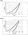
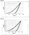
- Example 1 With respect to, as the Comparative Examples, the single-layered film of titanium nitride (Comparative Example 1), the single-layered film of titanium oxide (dark blue) (Comparative Example 2), the single-layered film of titanium oxide (bluish green) (Comparative Example 3), and the film having titanium oxide (bluish green) superimposed on titanium nitride (Comparative Example 4), indentation photographs ( FIGs. 4(a) to 4(e) ) and applied load curves ( FIGs. 5 to 7B ) are shown. It is to be noted that with respect to each of Example 1 and Comparative Examples 1 to 4, the measurement results of three spots (three indentation photographs and applied load curves) are shown. In the indentation photographs, one side is 9 ⁇ m. The abscissa in each of the applied load curves indicates a pushed-in depth.
- the three photographs lined up vertically in the column of FIG. 4 (a) are photographs showing the indentation shape of Example 1.
- the three photographs lined up vertically in the column of FIG. 4(b) are photographs showing the indentation shape of Comparative Example 1.
- the three photographs lined up vertically in the column of FIG. 4(c) are photographs showing the indentation shape of Comparative Example 2.
- the three photographs lined up vertically in the column of FIG. 4(d) are photographs showing the indentation shape of Comparative Example 3.
- the three photographs lined up vertically in the column of FIG. 4(e) are photographs showing the indentation shape of Comparative Example 4.
- FIG. 5 shows an applied load curve of Example 1;
- FIG. 6A shows an applied load curve of Comparative Example 1;
- FIG. 6B shows an applied load curve of Comparative Example 2;
- FIG. 7A shows an applied load curve of Comparative Example 3; and
- FIG. 7B shows an applied load curve of Comparative Example 4.
- Comparative Example 5 in which the beam output is less than 180 A (170 A) required a long time for the treatment and was inferior in the productivity. Examples 2 to 5 in which the beam output is 180 A to 280 A were good. Comparative Example 6 in which the beam output is more than 280 A (290 A) had color irregularity and was poor.
- Comparative Example 7 in which the oxygen gas partial pressure is less than 8.1 ⁇ 10 -2 Pa (8.0 ⁇ 10 -2 Pa) was low in the brightness (dark) and poor.
- Comparative Example 8 in which the oxygen gas partial pressure is more than 1.2 ⁇ 10 -1 Pa (1.3 ⁇ 10 -1 Pa) coating was impossible from the standpoint of performance of the ion plating apparatus.
- samples having a film thickness of the wear resistant layer of 0.70 ⁇ m and 0.75 ⁇ m, respectively were prepared.
- the color tone changes at a dizzying pace according to the change in the film thickness.
- the film thickness is preferably in a range of from 0.15 to 0.19 ⁇ m, and preferably from 0.16 to 0.18 ⁇ m. This range is the stage on the way of changing from the blue color of the second lap to the yellow color of the third lap.
- a sliding member for vehicular suspension including a wear resistant layer having appropriate mechanical strength and high designability on its outer peripheral sliding face and a method for producing the same are provided.
Landscapes
- Chemical & Material Sciences (AREA)
- Engineering & Computer Science (AREA)
- Mechanical Engineering (AREA)
- Chemical Kinetics & Catalysis (AREA)
- Materials Engineering (AREA)
- Metallurgy (AREA)
- Organic Chemistry (AREA)
- General Engineering & Computer Science (AREA)
- Inorganic Chemistry (AREA)
- Physical Vapour Deposition (AREA)
- Fluid-Damping Devices (AREA)
Abstract
Description
- The present invention relates to a sliding member for vehicular suspension and a method for producing the same.
- Hitherto, the surface of a sliding member for vehicular suspension, for example, the surface of an inner tube to be used for a front fork of motorcycle or bicycle, is subjected to a surface treatment for the purpose of improving the slidability or corrosion resistance. As a film to be formed by the surface treatment, a hard chromium plating film was general. In addition, as a special film, a titanium nitride film assuming a gold color, and a titanium oxide film assuming a dark blue or brown color, which are formed by the ion plating method, are known (see Patent Literature 1).
- In the sliding member for vehicular suspension, such as an inner tube, a part of the outer surface is exposed to the outside. For this reason, designability is also required for the sliding member. However, the color tone of the conventional hard chromium plating film is limited to a silver white metallic luster, so that its designability was poor. In addition, the titanium nitride film that is formed by the ion plating method is excellent in wear resistance, low frictional resistance, etc. and assumes a gold color, so that its designability is high; however, its color tone is limited to the gold color and lacks in variation. In addition, in the titanium oxide film, its color tone is also limited to a dark blue or brown color and lacks in variation.
- Patent Literature 1: Japanese Patent No.
3023530 - Then, an object of the present invention is to provide a sliding member for vehicular suspension including a wear resistant layer having appropriate mechanical strength and high designability on its outer peripheral sliding face and a method for producing the same.
- In the conventional technology, a titanium nitride film is applied on the surface of a titanium layer, and a titanium oxide film is applied on that surface. However, according to this conventional technology, there was involved such a problem that when once scratched due to sliding, the films are liable to be peeled at an interface between the titanium nitride film and the titanium oxide film starting at the scratch. In order to solve the foregoing problem, the present inventors made extensive and intensive investigations. As a result, they investigated replacement of the titanium nitride film with a wear resistant layer made of a titanium oxide film and a titanium film. According to this, it has been found that even when one scratched due to sliding, not only the films are hardly peeled, but also it becomes possible to improve the designability, thereby leading to accomplishment of the present invention.
- According to an aspect of the present invention,
there is provided a sliding member for vehicular suspension comprising, on its outer peripheral sliding face, a colored wear resistant layer formed by an ion plating method and having a film thickness of 0.75 µm or more and 10 µm or less,
the wear resistant layer including a dark blue titanium oxide layer, a titanium intermediate layer, and a colored titanium oxide layer, which are laminated in this order from an inner peripheral side toward an outer peripheral side of the sliding member. - In the above-described aspect of the present invention, the colored titanium oxide layer may be a bluish green titanium oxide layer having a film thickness of 0.15 µm or more and 0.19 µm or less.
- According to an aspect of the present invention,
there is provided a method for producing a sliding member for vehicular suspension including, on its outer peripheral sliding face, a colored wear resistant layer formed by an ion plating method and having a film thickness of 0.75 µm or more and 10 µm or less,
the wear resistant layer including a dark blue titanium oxide layer, a titanium intermediate layer, and a colored titanium oxide layer, which are laminated in this order from an inner peripheral side toward an outer peripheral side of the sliding member, wherein
the ion plating method comprises using an HCD type ion plating apparatus, setting a beam output of the apparatus on forming the colored titanium oxide layer to 180 to 280 A, and controlling an oxygen gas partial pressure within a vacuum tank of the apparatus to a range of 8.1 × 10⁻² Pa or more and 1.2 × 10⁻¹ Pa or less. - In the above-described aspect of the present invention, the colored titanium oxide layer may be a bluish green titanium oxide layer having a film thickness of 0.15 µm or more and 0.19 µm or less.
- In accordance with the present invention, a sliding member for vehicular suspension including a wear resistant layer having appropriate mechanical strength and high designability on its outer peripheral sliding face and a method for producing the same are provided.
-
-
FIG. 1 is a cross-sectional view of a sliding member for vehicular suspension by the Examples of the present invention. -
FIG. 2 is a view showing an ion plating apparatus that is used for carrying out the present invention. -
FIG. 3 is a view showing an adhesion test method. -
FIGs. 4(a) to 4(e) are photographs each of which shows an indentation shape,FIG. 4(a) is Example 1,FIG. 4(b) is Comparative Example 1,FIG. 4(c) is Comparative Example 2,FIG. 4(d) is Comparative Example 3, andFIG. 4(e) is Comparative Example 4. -
FIG. 5 is an applied load curve of Example 1. -
FIG. 6A is an applied load curve of Comparative Example 1. -
FIG. 6B is an applied load curve of Comparative Example 2. -
FIG. 7A is an applied load curve of Comparative Example 3. -
FIG. 7B is an applied load curve of Comparative Example 4. - Modes for carrying out the present invention are hereunder described specifically on the basis of the accompanying drawings. In the present invention, the wording "high designability" refers to the matter that an interference color is assumed. As shown in the sectional explanatory view of
FIG. 1 , a slidingmember 1 for vehicular suspension according to the Examples of the present invention includes a base material 2 of a cylindrical sliding member (one having a hard chromium plating 4 applied on a steel material 3) and a colored wearresistant layer 5 that is provided on an outer peripheral sliding face of the base material 2. This wearresistant layer 5 is formed by the ion plating method. Here, the wearresistant layer 5 is provided on the base material 2 via anundercoat layer 6 of titanium. The wearresistant layer 5 includes a dark blue titanium oxide layer 7, a titaniumintermediate layer 8, and a colored (yellow, reddish purple, or bluish green) titanium oxide layer 9, which are successively laminated from the inner peripheral side toward the outer peripheral side. - The dark blue titanium oxide layer 7, the titanium
intermediate layer 8, and the colored titanium oxide layer 9, which are laminated in this order from the inner peripheral side toward the outer peripheral side, are defined as a set of layer structure. The wearresistant layer 5 in the present invention has only to include at least one set of layer structure, and one or more sets of layer structure may be provided between the wearresistant layer 5 and the base material 2. For example, in the wearresistant layer 5 made of two sets of layer structure, the dark blue titanium oxide layer 7, the titaniumintermediate layer 8, and the colored titanium oxide layer 9 are successively laminated, and the dark blue titanium oxide layer 7, the titaniumintermediate layer 8, and the colored titanium oxide layer 9 are further successively laminated thereon. - Alternatively, a layer different from the foregoing layer may intervene between the base material 2 and the set of layer structure. For example, the wear
resistant layer 5 may be constituted such that the dark blue titanium oxide layer 7, the titaniumintermediate layer 8, and the colored titanium oxide layer 9 are successively laminated on a brown titanium oxide layer. In addition, the dark blue titanium oxide layer 7, the titaniumintermediate layer 8, the colored titanium oxide layer 9, titaniumintermediate layer 8, and the colored titanium oxide layer 9 may also be successively laminated. - It is to be noted that the
undercoat layer 6 may not be provided depending upon the material quality of the base material 2. InFIG. 1 , though the cylindrical sliding member is illustrated, there is a case of a round bar-shaped sliding member. - Examples of the sliding
member 1 for vehicular suspension include an inner tube of a front fork and a piston rod of a rear suspension of motorcycle, an inner tube of a front fork of bicycle, and an inner tube of a shock absorber of car. - The ion plating method is a vacuum deposition method utilizing a phenomenon in which an evaporated metal that has been ionized by discharge and a reactive gas form a film of a metal or ceramics while repeating an appropriate impact against the negatively impressed base material 2. In the vacuum deposition method, an electrically active evaporated metal is favorably attached to the base material 2 upon being given energy due to an electric field. According to this, a film having excellent adhesion can be formed.
- It is desired that a film thickness of the colored wear resistant layer 5 (the dark blue titanium oxide layer 7, the titanium
intermediate layer 8, and the colored titanium oxide layer 9) that is formed on the surface of the base material 2 of the sliding member by the foregoing ion plating method is in a range of from 0.75 to 10 µm, and preferably from 1 to 2 µm. When the film thickness is less than 0.75 µm, the designability is liable to be worsened due to a wear scar. On the other hand, though the upper limit of the film thickness is not particularly limited, in the case of thickening the film, only the dark blue titanium oxide layer 7 is thickened. As the dark blue titanium oxide layer 7 becomes thicker, a longer treatment time is required, resulting in high costs. When the dark blue titanium oxide layer 7 becomes extremely thick (exceeding 10 µm), it is liable to be peeled due to the impact. The film thickness ranging from 1 to 2 µm provides sufficient wear resistance and is advantageous in cost and practically useful. - In the wear
resistant layer 5, the titaniumintermediate layer 8 plays an important role for the purpose of obtaining a desired color (yellow, reddish purple, or bluish green color) while securing the film thickness of a predetermined value or more (0.75 µm or more) in order to keep the sufficient wear resistance. It is to be noted that as a material quality of the base material 2 of the sliding member for vehicular suspension, a structural alloy steel that is excellent in toughness is general. Alternately, as illustrated inFIG. 1 , the hard chromium plating 4 may be applied on such a structural alloy steel 3. Besides, an aluminum material, a carbon fiber material, and so on may also be used. - The titanium oxide film 9 serving as an outermost layer of the wear
resistant layer 5 assumes a color (yellow, reddish purple, or bluish green color). By properly controlling the treatment conditions by the ion plating method, particularly an introduction amount of an oxygen gas into a vacuum tank of an ion plating apparatus and a beam output, the titanium oxide film 9 can be colored to a desired color. The introduction amount of an oxygen gas is regulated according to the beam output (180 to 280 A, and preferably 200 to 260 A), to control an oxygen gas partial pressure within the vacuum tank to a range of from 8.1 × 10⁻² to 1.2 × 10⁻¹ Pa, and preferably from 9.7 × 10⁻² to 1.1 × 10⁻¹ Pa. When the oxygen gas partial pressure is more than 1.2 × 10⁻¹ Pa, a feeling of transparency increases and becomes polychromic, so that there is a case where the desired color is hardly obtained, or the coating treatment becomes difficult depending upon a performance of the ion plating apparatus. When the oxygen gas partial pressure is less than 8.1 × 10⁻² Pa, both chroma and brightness become low, and it becomes dark, so that the desired color is hardly obtained. When the beam output is less than 180 A, a long time is needed for the treatment, and the productivity is worsened. When the beam output is more than 280 A, a deposition rate becomes large, and the film thickness of each site on the member surface is scattered to cause color irregularity, so that the product value is lowered. - Specifically, in order to obtain the titanium oxide film 9 having a yellow, reddish purple, or bluish green color, for example, when the beam output is 260 A, the oxygen gas pressure is controlled to 1.1 × 10⁻¹ Pa. When the beam output is 200 A, the oxygen gas pressure is controlled to 9.7 × 10⁻² Pa.
- At the stage of introducing the oxygen gas, the color tone of the titanium oxide film 9 successively changes to yellow, red, and blue, and again changes to yellow, red, and blue, and this is repeated several times. However, as for the color tone, the brightness, the chroma, and the hue change every repetition. Then, at the point of time when the titanium oxide film 9 becomes the desired color, a shutter is closed to terminate the deposition.
- Though a film thickness of the titanium oxide film 9 is approximately 0.05 to 0.3 µm, the target film thickness varies with the color to be obtained. In the bluish green titanium oxide film 9, its film thickness is in a range of from 0.15 to 0.19 µm, and preferably from 0.16 to 0.18 µm. When the film thickness is more than 0.19 µm, the color becomes yellowish green to yellow, so that the bluish green color is not obtained, whereas when the film thickness is less than 0.15 µm, the color becomes reddish purple, so that the bluish green color is not obtained.
- An outline of an HCD (hollow cathode discharge) type
ion plating apparatus 10 that is used in the present invention is shown inFIG. 2 . InFIG. 2 , awork 12 that is an object to the coating treatment is arranged within avacuum tank 11. A water-cooledcopper hearth 14 for receiving a Tiraw material 13 that is a metal to be evaporated is arranged beneath thework 12. A hollow cathode-type electron gun (hollow cathode) 15 that melts and evaporates the Tiraw material 13 is provided right above thehearth 14. An Argas introduction pipe 16 is connected to thehollow cathode 15. A focusingcoil 17 for focusing electron beams to irradiate them on the Tiraw material 13 is arranged between thehearth 14 and thehollow cathode 15. - A
symbol 18 is an introduction pipe for introducing a reactive gas O2; asymbol 19 is a direct current bias power source for impressing a bias voltage to thework 12; asymbol 20 is a direct current power source for flowing a high-frequency superimposed direct current between thehollow cathode 15 and thehearth 14; and asymbol 21 is a vent. Aheater 22 for heating thework 12 is provided within thevacuum tank 11. Ashutter 23 is provided between thework 12 and the hollow cathode-type electron gun 15. - An example of a process of coating the wear resistant layer on the outer peripheral sliding face of the inner tube by using the above-described apparatus is shown. First of all, a stain or grease of a structural alloy steel-made inner tube base material to which a hard chromium plating serving as the work has been applied is removed. Furthermore, a pre-treatment for removing an oxide film on the outer peripheral face is performed. The
work 12 which has been subjected to the foregoing pre-treatment is installed in a non-illustrated tool within thevacuum tank 11, and the Tiraw material 13 is inserted into thehearth 14. - When the foregoing pre-treatment has been completed, the inside of the
vacuum tank 11 is allowed to reduce the pressure to approximately 7.7 × 10⁻³ Pa or less while heating to 300°C or higher (approximately 300 to 320°C), and after the work reaches the predetermined temperature, the temperature is kept for a fixed time (approximately 30 to 60 minutes). It is to be noted that the heating temperature may be higher than this temperature so long as the material quality of the metallographic structure or mechanical strength of the work does not alter. - Subsequently, a high-purity argon gas is introduced into the
vacuum tank 11, and a negative voltage of approximately 500 V is impressed to thework 12 under a pressure of approximately 4.67 × 10⁻² Pa, thereby performing cleaning of the work surface by means of an ion bombardment treatment. - Subsequently, an argon gas is introduced into the Ta-made
hollow cathode 15 to achieve ignition (the electric current is approximately 300A). Thetitanium 13 in thehearth 14 is melted, whereby the titanium evaporates, and after stabilized, the electric current is raised to approximately 360 A. By keeping for a fixed time (approximately 3 to 5 minutes), impurities, such as oxides, of the surface of thetitanium 13 accommodated in thehearth 14 are flied and removed. In the treatment process up to the moment, in order to prevent deposition of the impurities on thework 12 from occurring, theshutter 23 between thehearth 14 and thework 12 is closed. It is to be noted that as for the numerical values as described above, such as the temperatures, the pressures, the voltages, and the electric current values, only one example is shown, and it should be construed that they are not limited to the foregoing numerical values. - Subsequently, the
shutter 23 is opened, only the titanium is evaporated, and only the titanium is deposited on thework 12 to form theundercoat layer 6, thereby contemplating to improve the adhesion. A thickness of theundercoat layer 6 is preferably 0.05 to 0.2 µm from the standpoint of improving the adhesion. The processing is performed at a beam output of 320 to 360 A for an arbitrary time (approximately 1 to 3 minutes). - After undercoating the titanium, an oxygen gas is introduced from the reactive
gas introduction pipe 18, to form the titanium oxide film 7. At this time, the treatment conditions are set such that the beam output is 320 to 360 A; the oxygen gas partial pressure is 5.6 × 10⁻² to 7.3 × 10⁻² Pa; the bias voltage is 40 V; the heating temperature is 300 to 320°C; and the deposition time is 15 to 30 minutes. At the initial stage of introducing the oxygen gas, the color tone of the film 7 successively changes to yellow, red, and blue, and again changes to yellow, red, and blue, and this is repeated several times. However, as the film thickness of the film 7 becomes large, the color tone gradually becomes cloudy and assumes a dark blue color. After this, even if the film thickness becomes larger, the color tone becomes constant. - After reaching the predetermined time, the introduction of the oxygen gas is stopped, the beam output is decreased to 200 to 260 A, and only the titanium is deposited in a thickness of approximately 0.05 to 0.2 µm for an arbitrary time (approximately 1 to 2 minutes) in the same manner as in the undercoat layer, thereby forming an intermediate titanium layer. This step is necessary for regulating the chroma, the brightness, and the hue of the colored color to be deposited, and the desired color can be obtained by this step.
- Subsequently, the oxygen gas is again introduced (the oxygen gas partial pressure is 8.1 × 10⁻² to 1.2 × 10⁻¹ Pa, and preferably 9.7 × 10⁻² to 1.1 × 10⁻¹ Pa), and the beam output is regulated to 180 to 280 A, and preferably 200 to 260 A, thereby depositing a titanium oxide film. Here, at the initial stage of introducing the oxygen gas, the color tone successively changes to yellow, red, and blue, and again changes to yellow, red, and blue.
- This time is the stage on the way where the bluish green system to be obtained changes from the blue color of the second lap to the yellow color of the third lap in the color change, and when reaching the desired color, the shutter is closed to terminate the deposition.
- On the structural alloy steel-made base material 2 having the hard chromium plating 4 serving as the work applied thereto, the ion plating treatment was performed under the treatment conditions shown in Table 1, thereby preparing samples of Example 1 and Comparative Examples 1 to 4, followed by performing a durability test and judgement for film thickness, designability, etc. The results are also shown in Table 1. In Table 1, as for the beam output and the gas partial pressure, the treatment conditions on the occasion of forming a titanium oxide film or a titanium nitride film that is an outermost layer are shown.
[Table 1] Film quality Color tone Beam output Gas partial pressure (Pa) Film thickness (µm) Judgement of indentation observation Judgement of designability of sliding scar free from influence against functions Overall judgement Example 1 Titanium undercoat + titanium oxide (dark blue) + titanium intermediate layer + titanium oxide (bluish green) Bluish green 230 A O2: 9.7 × 10⁻² to 1.1 × 10⁻¹ 1.05 Good The designability is high; the exposure of Cr plating is not observed; and though the exposure of titanium oxide (dark blue) layer is observed but not noticeable. Good Comparative Example 1 Titanium undercoat + titanium nitride Gold 230 A N2: 1.7 × 10⁻¹ to 1.7 × 10⁻¹ 0.98 Good The designability is high; and the exposure of Cr plating is not observed. Exclusive Comparative Example 2 Titanium undercoat + titanium oxide (dark blue) Dark blue 230 A O2: 6.2 × 10⁻² to 6.4 × 10⁻² 1.29 Good The designability is high; and the exposure of Cr plating is not observed. Exclusive Comparative Example 3 Titanium oxide (bluish green) Bluish green 230 A O2: 9.7 × 10⁻² to 9.7 × 10⁻² 0.18 Good The designability is low; and the exposure of Cr plating is observed. Poor Comparative Example 4 Titanium undercoat + titanium nitride + titanium oxide (bluish green) Bluish green 230 A O2: 9.7 × 10⁻² to 9.7 × 10⁻² 0.88 Poor The designability is low; and the exposure of TiN layer is noticeable. Poor - Here, the test of durability was evaluated in terms of adhesion (peeling resistance) with the following micro hardness tester. That is, so far as a micro hardness tester ("Nanoindentation Tester", manufactured by Anton Paar) 25, an outline of which is shown in
FIG. 3 , was used; aBerkovich indenter 26 having a triangular pyramid shape was pushed into asample 27 at a load (Fz) of 50 mN (milliNewton); the peripheral state of the indentation generated by theindenter 26 was observed, and as a result, no peeling was confirmed; and an applied load curve was a smooth quadratic curve, such case was considered to be acceptable. - Besides Example 1, with respect to, as the Comparative Examples, the single-layered film of titanium nitride (Comparative Example 1), the single-layered film of titanium oxide (dark blue) (Comparative Example 2), the single-layered film of titanium oxide (bluish green) (Comparative Example 3), and the film having titanium oxide (bluish green) superimposed on titanium nitride (Comparative Example 4), indentation photographs (
FIGs. 4(a) to 4(e) ) and applied load curves (FIGs. 5 to 7B ) are shown. It is to be noted that with respect to each of Example 1 and Comparative Examples 1 to 4, the measurement results of three spots (three indentation photographs and applied load curves) are shown. In the indentation photographs, one side is 9 µm. The abscissa in each of the applied load curves indicates a pushed-in depth. - The three photographs lined up vertically in the column of
FIG. 4 (a) are photographs showing the indentation shape of Example 1. The three photographs lined up vertically in the column ofFIG. 4(b) are photographs showing the indentation shape of Comparative Example 1. The three photographs lined up vertically in the column ofFIG. 4(c) are photographs showing the indentation shape of Comparative Example 2. The three photographs lined up vertically in the column ofFIG. 4(d) are photographs showing the indentation shape of Comparative Example 3. The three photographs lined up vertically in the column ofFIG. 4(e) are photographs showing the indentation shape of Comparative Example 4. -
FIG. 5 shows an applied load curve of Example 1;FIG. 6A shows an applied load curve of Comparative Example 1;FIG. 6B shows an applied load curve of Comparative Example 2;FIG. 7A shows an applied load curve of Comparative Example 3; andFIG. 7B shows an applied load curve of Comparative Example 4. - As noted from these results, the single-layered film of titanium nitride (Comparative Example 1), the single-layered film of titanium oxide (dark blue) (Comparative Example 2), and the single-layered of titanium oxide (bluish green) (Comparative Example 3) are free from peeling in the indentation portion and good (
FIGs. 4(b) to 4(d) ). - In the single-layered film of titanium oxide (bluish green) (Comparative Example 3), though the results of the peeling test with the micro hardness tester are good (see
FIG. 4(d) ), since the film thickness is thin, the chromium plating layer is exposed due to a wear scar, thereby impairing the designability (see Table 1). But, even when the film thickness is thin in this way, the functionality is not impaired. - In the film having titanium oxide (bluish green) superimposed on titanium nitride (Comparative Example 4), as is clear from the photographs regarding the test results with the micro hardness tester (
FIG. 4(e) ), peeling is generated in the indentation portion, and therefore, it is not suitable for practical use. In addition, the applied load curve does not become a smooth quadratic curve (FIG. 7B ), and it is poor. - In the film according to Example 1, in which the titanium intermediate layer and the titanium oxide (bluish green) are superimposed on the titanium oxide (dark blue), no peeling is generated in the indentation portion (
FIG. 4(a) ). The bluish green color and the dark blue color have a similar color to each other. For this reason, in the wear resistant layer of Example 1, even when the titanium oxide (dark blue) film is exposed from the titanium oxide (bluish green) film due to the wear scar, the exposed portion of the titanium oxide (dark blue) film is hardly noticeable from the titanium oxide (bluish green) film. In addition, the wear resistant layer of Example 1 has a desired color (bluish green system). In this way, the wear resistant layer of Example 1 is extremely excellent in the designability. In addition, the applied load curve becomes a smooth quadratic curve), and it is good (FIG. 5 ). In addition, even when the film thickness is thin in this way, there is no problem from the standpoint of functionality. - As to the treatment conditions on the occasion of forming the titanium oxide film that is an outermost layer, the beam output was changed in various ways to prepare samples, which were then evaluated. The results are shown in Table 2.
[Table 2] Beam output (A) Film thickness (µm) Color irregularity in the rotational direction Evaluation Good or not Comparative Example 5 170 0.17 No Long time is required Poor Example 2 180 0.15 No Good Good Example 3 200 0.17 No Good Good Example 4 260 0.18 No Good Good Example 5 280 0.18 No Good Good Comparative Example 6 290 0.17 Yes Color irregularity is present Poor - As noted from the results of Table 2, Comparative Example 5 in which the beam output is less than 180 A (170 A) required a long time for the treatment and was inferior in the productivity. Examples 2 to 5 in which the beam output is 180 A to 280 A were good. Comparative Example 6 in which the beam output is more than 280 A (290 A) had color irregularity and was poor.
- As to the treatment conditions on the occasion of forming the titanium oxide film that is an outermost layer, the oxygen gas partial pressure was changed in various ways to prepare samples, which were then evaluated. The results are shown in Table 3.
[Table 3] Beam output (A) Oxygen partial pressure (Pa) Film thickness (µm) Chroma and brightness Good or not Comparative Example 7 230 8.0 × 10^2 0.17 Dark Poor Example 6 230 8.1 × 10^2 0.17 Good Good Example 7 230 9.7 × 10^2 0.17 Good Good Example 8 230 1.1 × 10^1 0.18 Good Good Example 9 230 1.2 × 10^1 0.17 Good Good Comparative Example 8 230 1.3 × 10^1 - Impossible for coating from the standpoint of performance of apparatus - - As noted from the results of Table 3, Comparative Example 7 in which the oxygen gas partial pressure is less than 8.1 × 10⁻² Pa (8.0 × 10⁻² Pa) was low in the brightness (dark) and poor. Examples 6 to 9 in which the oxygen gas partial pressure is 8.1 × 10⁻² Pa to 1.2 × 10⁻¹ Pa were good in both the brightness and the chroma. In Comparative Example 8 in which the oxygen gas partial pressure is more than 1.2 × 10⁻¹ Pa (1.3 × 10⁻¹ Pa), coating was impossible from the standpoint of performance of the ion plating apparatus.
- In order to verify the lower limit value of the total film thickness of the wear resistant layer, samples having a film thickness of the wear resistant layer of 0.70 µm and 0.75 µm, respectively were prepared.
- When the total film thickness of the titanium intermediate film and the colored titanium oxide layer was 0.20 µm, the color tone exhibited a bluish green system. In consequence, in order that the total film thickness of the wear resistant layer may become 0.70 µm, the film thickness of the dark blue titanium oxide layer becomes 0.50 µm; and in order that the total film thickness may become 0.75 µm, the film thickness of the dark blue titanium oxide layer becomes 0.55 µm. Then, the samples having a film thickness of the dark blue titanium oxide layer of 0.50 µm and 0.55 µm, respectively were prepared and evaluated. The results are shown in Table 4.
[Table 4] Beam output (A) Film thickness of dark blue titanium oxide layer (µm) Evaluation Good or not Comparative Example 9 335 0.50 The color tone is brownish; and the wear scar is brown. Poor Example 10 330 0.55 The color tone is dark blue; and the wear scar is dark blue. Good - As noted from the results of Table 4, in Comparative Example 9 in which the film thickness of the dark blue titanium oxide layer is 0.50 µm, the color tone was not dark blue but brownish. For this reason, the wear scar became brown, and the brown wear scar was noticeable on the bluish green ground, so that the designability was inferior.
- On the other hand, Example 10 in which the film thickness of the dark blue titanium oxide layer is 0.55 µm assumed a dark blue color tone. For this reason, the wear scar became dark blue, and the dark blue wear scar was hardly noticeable on the bluish green ground, so that the designability was not significantly worsened.
- A test was performed for the purpose of examining a relation between the color tone and the film thickness of the colored titanium oxide layer serving as an outermost layer. The results are shown in Table 5.
[Table 5] Film thickness (µm) Color tone 0.04 Bright yellow 0.05 Bluish purple 0.06 Blue 0.08 Light blue 0.09 Transparent 0.10 Yellow 0.11 Yellow 0.12 Bright yellow 0.14 Reddish purple 0.15 Bluish purple + bluish green 0.16 Bluish green 0.17 Bluish green 0.18 Bluish green 0.19 Bluish green + green 0.20 Green + bluish green 0.21 Green 0.23 Yellowish green + yellow 0.25 Reddish purple 0.27 Bluish green 0.28 Bluish green 0.29 Green 0.30 Green 0.31 Green - In the foregoing, while the outline has been described in such a manner that the color tone successively changes to yellow, red, and blue, and again changes to yellow, red, and blue, in more detail, as noted from the results of Table 5, the color tone changes at a dizzying pace according to the change in the film thickness. In the course where the color tone changes at a dizzying pace in this way, by stopping the treatment at the stage of reaching the desired color tone, a product having a desired color tone is obtained. Among those, it may be said that as the bluish green color, the film thickness is preferably in a range of from 0.15 to 0.19 µm, and preferably from 0.16 to 0.18 µm. This range is the stage on the way of changing from the blue color of the second lap to the yellow color of the third lap.
- It is to be noted that in the above-described treatment process, it is desired to regulate the film thickness of the oxide film to be deposited on the work such that it is uniform in all of the proportions by rotating the work or moving it right and left. In addition, a color tone with reproducibility is hardly obtained unless the amount of Ti flied from the evaporation source is uniform, and therefore, it is desired to regulate the amount of Ti within the hearth every time such that the flying amount of Ti is constant in every batch.
- The present application is based on a Japanese patent application filed on June 17, 2016 (Japanese Patent Application No.
2016-120468 2017-87733 - In accordance with the present invention, a sliding member for vehicular suspension including a wear resistant layer having appropriate mechanical strength and high designability on its outer peripheral sliding face and a method for producing the same are provided.
-
- 1
- Sliding member for vehicular suspension
- 2
- Base material
- 3
- Steel material (structural alloy steel)
- 4
- Hard chromium plating
- 5
- Wear resistant layer
- 6
- Undercoat layer
- 7
- Dark blue titanium oxide layer
- 8
- Titanium intermediate layer
- 9
- Colored titanium oxide layer
- 10
- HCD type ion plating apparatus
- 11
- Vacuum tank
- 12
- Work
- 13
- Ti raw material
- 14
- Hearth
- 15
- Hollow cathode-type electron gun (hollow cathode)
- 16
- Ar gas introduction pipe
- 17
- Focusing coil
- 18
- Reactive gas introduction pipe
- 19
- Direct current bias power source
- 20
- Direct current power source
- 21
- Vent
- 22
- Heater
- 23
- Shutter
- 25
- Micro hardness tester
- 26
- Berkovich indenter
- 27
- Sample
Claims (4)
- A sliding member for vehicular suspension comprising, on its outer peripheral sliding face, a colored wear resistant layer formed by an ion plating method and having a film thickness of 0.75 µm or more and 10 µm or less,
the wear resistant layer including a dark blue titanium oxide layer, a titanium intermediate layer, and a colored titanium oxide layer, which are laminated in this order from an inner peripheral side toward an outer peripheral side of the sliding member. - The sliding member for vehicular suspension according to claim 1, wherein the colored titanium oxide layer is a bluish green titanium oxide layer having a film thickness of 0.15 µm or more and 0.19 µm or less.
- A method for producing a sliding member for vehicular suspension including, on its outer peripheral sliding face, a colored wear resistant layer formed by an ion plating method and having a film thickness of 0.75 µm or more and 10 µm or less,
the wear resistant layer including a dark blue titanium oxide layer, a titanium intermediate layer, and a colored titanium oxide layer, which are laminated in this order from an inner peripheral side toward an outer peripheral side of the sliding member, wherein
the ion plating method comprises using an HCD type ion plating apparatus, setting a beam output of the apparatus on forming the colored titanium oxide layer to 180 to 280 A, and controlling an oxygen gas partial pressure within a vacuum tank of the apparatus to a range of 8.1 × 10⁻² Pa or more and 1.2 × 10⁻¹ Pa or less. - The method for producing the sliding member for vehicular suspension according to claim 3, wherein the colored titanium oxide layer is a bluish green titanium oxide layer having a film thickness of 0.15 µm or more and 0.19 µm or less.
Applications Claiming Priority (3)
| Application Number | Priority Date | Filing Date | Title |
|---|---|---|---|
| JP2016120468 | 2016-06-17 | ||
| JP2017087733 | 2017-04-26 | ||
| PCT/JP2017/022184 WO2017217506A1 (en) | 2016-06-17 | 2017-06-15 | Sliding member for vehicular suspension, and method for manufacturing sliding member |
Publications (3)
| Publication Number | Publication Date |
|---|---|
| EP3473886A1 true EP3473886A1 (en) | 2019-04-24 |
| EP3473886A4 EP3473886A4 (en) | 2020-03-11 |
| EP3473886B1 EP3473886B1 (en) | 2021-10-20 |
Family
ID=60664454
Family Applications (1)
| Application Number | Title | Priority Date | Filing Date |
|---|---|---|---|
| EP17813400.3A Active EP3473886B1 (en) | 2016-06-17 | 2017-06-15 | Sliding member for vehicular suspension, and method for manufacturing sliding member |
Country Status (4)
| Country | Link |
|---|---|
| US (1) | US10844471B2 (en) |
| EP (1) | EP3473886B1 (en) |
| JP (1) | JP6884775B2 (en) |
| WO (1) | WO2017217506A1 (en) |
Family Cites Families (10)
| Publication number | Priority date | Publication date | Assignee | Title |
|---|---|---|---|---|
| JPS6362867A (en) * | 1986-09-02 | 1988-03-19 | Seikosha Co Ltd | Colored article |
| USRE34173E (en) * | 1988-10-11 | 1993-02-02 | Midwest Research Technologies, Inc. | Multi-layer wear resistant coatings |
| JP3023530B2 (en) * | 1994-07-07 | 2000-03-21 | 有限会社伊藤鋼材加工センター | Method for manufacturing sliding member of vehicle suspension having titanium oxide coating |
| JPH07207446A (en) * | 1994-12-28 | 1995-08-08 | Niigata Eng Co Ltd | Forming method of titanium coating film |
| DE19511628C2 (en) * | 1995-03-30 | 2001-05-17 | Walter Hunger | Method for coating a tread of a piston rod of a hydraulic piston-cylinder unit |
| EP0903204A3 (en) * | 1997-09-22 | 2002-04-10 | SANYO ELECTRIC Co., Ltd. | Sliding member, inner and outer blades of an electric shaver and film-forming method |
| JP2005282589A (en) * | 2004-03-26 | 2005-10-13 | Showa Corp | Sliding member and surface treatment method of sliding member |
| CN101092309A (en) * | 2007-02-02 | 2007-12-26 | 冯健生 | A composite ceramic brick |
| DE202008007669U1 (en) * | 2008-06-09 | 2008-10-09 | Kamm, Thomas | Nanofarbschichtsystem on spring / damper elements as a lubricating film and spring travel indicator |
| DE212014000269U1 (en) * | 2014-06-23 | 2017-01-27 | Apple Inc. | Interference coloring of thick, porous oxide films |
-
2017
- 2017-06-15 US US16/307,403 patent/US10844471B2/en active Active
- 2017-06-15 WO PCT/JP2017/022184 patent/WO2017217506A1/en not_active Ceased
- 2017-06-15 JP JP2018524010A patent/JP6884775B2/en active Active
- 2017-06-15 EP EP17813400.3A patent/EP3473886B1/en active Active
Also Published As
| Publication number | Publication date |
|---|---|
| JP6884775B2 (en) | 2021-06-09 |
| WO2017217506A1 (en) | 2017-12-21 |
| EP3473886B1 (en) | 2021-10-20 |
| US20190301005A1 (en) | 2019-10-03 |
| JPWO2017217506A1 (en) | 2019-05-16 |
| EP3473886A4 (en) | 2020-03-11 |
| US10844471B2 (en) | 2020-11-24 |
Similar Documents
| Publication | Publication Date | Title |
|---|---|---|
| US10487412B2 (en) | Chromium-containing coating, a method for its production and a coated object | |
| CN105849633B (en) | W-Ni sputter target | |
| EP3676421B1 (en) | Zn-mg coated metallic substrate, method and installation for making it | |
| DE102013109706B4 (en) | Method of shape compensation and recovery using HVOF injection | |
| EP3835452B1 (en) | Method for manufacturing a decorative surface | |
| US4758280A (en) | Decorative black wear protection coating | |
| US20200277707A1 (en) | Method for producing coating with colored surface | |
| US20090130436A1 (en) | Spray coating member having excellent heat emmision property and so on and method for producing the same | |
| US11555240B2 (en) | Black plated steel sheet and manufacturing method thereof | |
| US20170036258A1 (en) | Hard coating film having anti-adhesion property to soft metal | |
| GB2202237A (en) | Cathodic arc plasma deposition of hard coatings | |
| EP3473886B1 (en) | Sliding member for vehicular suspension, and method for manufacturing sliding member | |
| CN111032901A (en) | Coated metal substrate | |
| DE19629728A1 (en) | Process for coating brass | |
| CN102031483B (en) | Method for performing surface treatment on golf head by forming carbon, nitrogen, titanium, chromium composite coating | |
| US20250305110A1 (en) | Metal free coating comprising tetrahedral hydrogen-free amorphous carbon | |
| EP3375904B1 (en) | Cylindrical titanium oxide sputtering target and process for manufacturing the same | |
| DE102005055035B4 (en) | Hard material-coated glass or glass-ceramic article, process for its production and its use | |
| JPS63125660A (en) | External parts for timepiece | |
| JP3023530B2 (en) | Method for manufacturing sliding member of vehicle suspension having titanium oxide coating | |
| US20170233858A9 (en) | Dark surface finishes on titanium alloys | |
| JPH08176804A (en) | Method of surface-treating metallic member | |
| CN115612887B (en) | High-strength k gold jewelry and preparation method thereof | |
| JP6568770B2 (en) | Colored titanium material | |
| JP2007254851A (en) | Metallic oxide film, and member coated with the metallic oxide film |
Legal Events
| Date | Code | Title | Description |
|---|---|---|---|
| STAA | Information on the status of an ep patent application or granted ep patent |
Free format text: STATUS: THE INTERNATIONAL PUBLICATION HAS BEEN MADE |
|
| PUAI | Public reference made under article 153(3) epc to a published international application that has entered the european phase |
Free format text: ORIGINAL CODE: 0009012 |
|
| STAA | Information on the status of an ep patent application or granted ep patent |
Free format text: STATUS: REQUEST FOR EXAMINATION WAS MADE |
|
| 17P | Request for examination filed |
Effective date: 20181206 |
|
| AK | Designated contracting states |
Kind code of ref document: A1 Designated state(s): AL AT BE BG CH CY CZ DE DK EE ES FI FR GB GR HR HU IE IS IT LI LT LU LV MC MK MT NL NO PL PT RO RS SE SI SK SM TR |
|
| AX | Request for extension of the european patent |
Extension state: BA ME |
|
| DAV | Request for validation of the european patent (deleted) | ||
| DAX | Request for extension of the european patent (deleted) | ||
| A4 | Supplementary search report drawn up and despatched |
Effective date: 20200207 |
|
| RIC1 | Information provided on ipc code assigned before grant |
Ipc: C23C 14/32 20060101ALI20200203BHEP Ipc: C23C 28/00 20060101ALI20200203BHEP Ipc: C23C 14/08 20060101ALI20200203BHEP Ipc: B62K 25/08 20060101ALI20200203BHEP Ipc: F16F 9/32 20060101AFI20200203BHEP |
|
| RIC1 | Information provided on ipc code assigned before grant |
Ipc: C23C 28/00 20060101ALI20200827BHEP Ipc: F16F 9/32 20060101AFI20200827BHEP Ipc: B62K 25/06 20060101ALI20200827BHEP Ipc: C23C 14/08 20060101ALI20200827BHEP Ipc: C23C 14/32 20060101ALI20200827BHEP Ipc: B62K 25/08 20060101ALI20200827BHEP |
|
| GRAP | Despatch of communication of intention to grant a patent |
Free format text: ORIGINAL CODE: EPIDOSNIGR1 |
|
| STAA | Information on the status of an ep patent application or granted ep patent |
Free format text: STATUS: GRANT OF PATENT IS INTENDED |
|
| INTG | Intention to grant announced |
Effective date: 20201102 |
|
| GRAS | Grant fee paid |
Free format text: ORIGINAL CODE: EPIDOSNIGR3 |
|
| GRAJ | Information related to disapproval of communication of intention to grant by the applicant or resumption of examination proceedings by the epo deleted |
Free format text: ORIGINAL CODE: EPIDOSDIGR1 |
|
| GRAL | Information related to payment of fee for publishing/printing deleted |
Free format text: ORIGINAL CODE: EPIDOSDIGR3 |
|
| STAA | Information on the status of an ep patent application or granted ep patent |
Free format text: STATUS: REQUEST FOR EXAMINATION WAS MADE |
|
| INTC | Intention to grant announced (deleted) | ||
| GRAP | Despatch of communication of intention to grant a patent |
Free format text: ORIGINAL CODE: EPIDOSNIGR1 |
|
| STAA | Information on the status of an ep patent application or granted ep patent |
Free format text: STATUS: GRANT OF PATENT IS INTENDED |
|
| INTG | Intention to grant announced |
Effective date: 20210510 |
|
| GRAA | (expected) grant |
Free format text: ORIGINAL CODE: 0009210 |
|
| STAA | Information on the status of an ep patent application or granted ep patent |
Free format text: STATUS: THE PATENT HAS BEEN GRANTED |
|
| AK | Designated contracting states |
Kind code of ref document: B1 Designated state(s): AL AT BE BG CH CY CZ DE DK EE ES FI FR GB GR HR HU IE IS IT LI LT LU LV MC MK MT NL NO PL PT RO RS SE SI SK SM TR |
|
| REG | Reference to a national code |
Ref country code: GB Ref legal event code: FG4D |
|
| REG | Reference to a national code |
Ref country code: CH Ref legal event code: EP |
|
| REG | Reference to a national code |
Ref country code: DE Ref legal event code: R096 Ref document number: 602017047983 Country of ref document: DE |
|
| REG | Reference to a national code |
Ref country code: IE Ref legal event code: FG4D |
|
| REG | Reference to a national code |
Ref country code: AT Ref legal event code: REF Ref document number: 1440197 Country of ref document: AT Kind code of ref document: T Effective date: 20211115 |
|
| REG | Reference to a national code |
Ref country code: LT Ref legal event code: MG9D |
|
| REG | Reference to a national code |
Ref country code: NL Ref legal event code: MP Effective date: 20211020 |
|
| REG | Reference to a national code |
Ref country code: AT Ref legal event code: MK05 Ref document number: 1440197 Country of ref document: AT Kind code of ref document: T Effective date: 20211020 |
|
| RAP2 | Party data changed (patent owner data changed or rights of a patent transferred) |
Owner name: HITACHI AUTOMOTIVE SYSTEMS, LTD. Owner name: RC-LOGO CO., LTD. |
|
| PG25 | Lapsed in a contracting state [announced via postgrant information from national office to epo] |
Ref country code: RS Free format text: LAPSE BECAUSE OF FAILURE TO SUBMIT A TRANSLATION OF THE DESCRIPTION OR TO PAY THE FEE WITHIN THE PRESCRIBED TIME-LIMIT Effective date: 20211020 Ref country code: LT Free format text: LAPSE BECAUSE OF FAILURE TO SUBMIT A TRANSLATION OF THE DESCRIPTION OR TO PAY THE FEE WITHIN THE PRESCRIBED TIME-LIMIT Effective date: 20211020 Ref country code: FI Free format text: LAPSE BECAUSE OF FAILURE TO SUBMIT A TRANSLATION OF THE DESCRIPTION OR TO PAY THE FEE WITHIN THE PRESCRIBED TIME-LIMIT Effective date: 20211020 Ref country code: BG Free format text: LAPSE BECAUSE OF FAILURE TO SUBMIT A TRANSLATION OF THE DESCRIPTION OR TO PAY THE FEE WITHIN THE PRESCRIBED TIME-LIMIT Effective date: 20220120 Ref country code: AT Free format text: LAPSE BECAUSE OF FAILURE TO SUBMIT A TRANSLATION OF THE DESCRIPTION OR TO PAY THE FEE WITHIN THE PRESCRIBED TIME-LIMIT Effective date: 20211020 |
|
| PG25 | Lapsed in a contracting state [announced via postgrant information from national office to epo] |
Ref country code: IS Free format text: LAPSE BECAUSE OF FAILURE TO SUBMIT A TRANSLATION OF THE DESCRIPTION OR TO PAY THE FEE WITHIN THE PRESCRIBED TIME-LIMIT Effective date: 20220220 Ref country code: SE Free format text: LAPSE BECAUSE OF FAILURE TO SUBMIT A TRANSLATION OF THE DESCRIPTION OR TO PAY THE FEE WITHIN THE PRESCRIBED TIME-LIMIT Effective date: 20211020 Ref country code: PT Free format text: LAPSE BECAUSE OF FAILURE TO SUBMIT A TRANSLATION OF THE DESCRIPTION OR TO PAY THE FEE WITHIN THE PRESCRIBED TIME-LIMIT Effective date: 20220221 Ref country code: PL Free format text: LAPSE BECAUSE OF FAILURE TO SUBMIT A TRANSLATION OF THE DESCRIPTION OR TO PAY THE FEE WITHIN THE PRESCRIBED TIME-LIMIT Effective date: 20211020 Ref country code: NO Free format text: LAPSE BECAUSE OF FAILURE TO SUBMIT A TRANSLATION OF THE DESCRIPTION OR TO PAY THE FEE WITHIN THE PRESCRIBED TIME-LIMIT Effective date: 20220120 Ref country code: NL Free format text: LAPSE BECAUSE OF FAILURE TO SUBMIT A TRANSLATION OF THE DESCRIPTION OR TO PAY THE FEE WITHIN THE PRESCRIBED TIME-LIMIT Effective date: 20211020 Ref country code: LV Free format text: LAPSE BECAUSE OF FAILURE TO SUBMIT A TRANSLATION OF THE DESCRIPTION OR TO PAY THE FEE WITHIN THE PRESCRIBED TIME-LIMIT Effective date: 20211020 Ref country code: HR Free format text: LAPSE BECAUSE OF FAILURE TO SUBMIT A TRANSLATION OF THE DESCRIPTION OR TO PAY THE FEE WITHIN THE PRESCRIBED TIME-LIMIT Effective date: 20211020 Ref country code: GR Free format text: LAPSE BECAUSE OF FAILURE TO SUBMIT A TRANSLATION OF THE DESCRIPTION OR TO PAY THE FEE WITHIN THE PRESCRIBED TIME-LIMIT Effective date: 20220121 Ref country code: ES Free format text: LAPSE BECAUSE OF FAILURE TO SUBMIT A TRANSLATION OF THE DESCRIPTION OR TO PAY THE FEE WITHIN THE PRESCRIBED TIME-LIMIT Effective date: 20211020 |
|
| RAP2 | Party data changed (patent owner data changed or rights of a patent transferred) |
Owner name: HITACHI ASTEMO, LTD. Owner name: RC-LOGO CO., LTD. |
|
| REG | Reference to a national code |
Ref country code: DE Ref legal event code: R097 Ref document number: 602017047983 Country of ref document: DE |
|
| PG25 | Lapsed in a contracting state [announced via postgrant information from national office to epo] |
Ref country code: SM Free format text: LAPSE BECAUSE OF FAILURE TO SUBMIT A TRANSLATION OF THE DESCRIPTION OR TO PAY THE FEE WITHIN THE PRESCRIBED TIME-LIMIT Effective date: 20211020 Ref country code: SK Free format text: LAPSE BECAUSE OF FAILURE TO SUBMIT A TRANSLATION OF THE DESCRIPTION OR TO PAY THE FEE WITHIN THE PRESCRIBED TIME-LIMIT Effective date: 20211020 Ref country code: RO Free format text: LAPSE BECAUSE OF FAILURE TO SUBMIT A TRANSLATION OF THE DESCRIPTION OR TO PAY THE FEE WITHIN THE PRESCRIBED TIME-LIMIT Effective date: 20211020 Ref country code: EE Free format text: LAPSE BECAUSE OF FAILURE TO SUBMIT A TRANSLATION OF THE DESCRIPTION OR TO PAY THE FEE WITHIN THE PRESCRIBED TIME-LIMIT Effective date: 20211020 Ref country code: DK Free format text: LAPSE BECAUSE OF FAILURE TO SUBMIT A TRANSLATION OF THE DESCRIPTION OR TO PAY THE FEE WITHIN THE PRESCRIBED TIME-LIMIT Effective date: 20211020 Ref country code: CZ Free format text: LAPSE BECAUSE OF FAILURE TO SUBMIT A TRANSLATION OF THE DESCRIPTION OR TO PAY THE FEE WITHIN THE PRESCRIBED TIME-LIMIT Effective date: 20211020 |
|
| PLBE | No opposition filed within time limit |
Free format text: ORIGINAL CODE: 0009261 |
|
| STAA | Information on the status of an ep patent application or granted ep patent |
Free format text: STATUS: NO OPPOSITION FILED WITHIN TIME LIMIT |
|
| 26N | No opposition filed |
Effective date: 20220721 |
|
| PG25 | Lapsed in a contracting state [announced via postgrant information from national office to epo] |
Ref country code: AL Free format text: LAPSE BECAUSE OF FAILURE TO SUBMIT A TRANSLATION OF THE DESCRIPTION OR TO PAY THE FEE WITHIN THE PRESCRIBED TIME-LIMIT Effective date: 20211020 |
|
| PG25 | Lapsed in a contracting state [announced via postgrant information from national office to epo] |
Ref country code: SI Free format text: LAPSE BECAUSE OF FAILURE TO SUBMIT A TRANSLATION OF THE DESCRIPTION OR TO PAY THE FEE WITHIN THE PRESCRIBED TIME-LIMIT Effective date: 20211020 |
|
| PG25 | Lapsed in a contracting state [announced via postgrant information from national office to epo] |
Ref country code: MC Free format text: LAPSE BECAUSE OF FAILURE TO SUBMIT A TRANSLATION OF THE DESCRIPTION OR TO PAY THE FEE WITHIN THE PRESCRIBED TIME-LIMIT Effective date: 20211020 |
|
| REG | Reference to a national code |
Ref country code: CH Ref legal event code: PL |
|
| REG | Reference to a national code |
Ref country code: BE Ref legal event code: MM Effective date: 20220630 |
|
| PG25 | Lapsed in a contracting state [announced via postgrant information from national office to epo] |
Ref country code: LU Free format text: LAPSE BECAUSE OF NON-PAYMENT OF DUE FEES Effective date: 20220615 Ref country code: LI Free format text: LAPSE BECAUSE OF NON-PAYMENT OF DUE FEES Effective date: 20220630 Ref country code: IE Free format text: LAPSE BECAUSE OF NON-PAYMENT OF DUE FEES Effective date: 20220615 Ref country code: FR Free format text: LAPSE BECAUSE OF NON-PAYMENT OF DUE FEES Effective date: 20220630 Ref country code: CH Free format text: LAPSE BECAUSE OF NON-PAYMENT OF DUE FEES Effective date: 20220630 |
|
| PG25 | Lapsed in a contracting state [announced via postgrant information from national office to epo] |
Ref country code: IT Free format text: LAPSE BECAUSE OF FAILURE TO SUBMIT A TRANSLATION OF THE DESCRIPTION OR TO PAY THE FEE WITHIN THE PRESCRIBED TIME-LIMIT Effective date: 20211020 Ref country code: BE Free format text: LAPSE BECAUSE OF NON-PAYMENT OF DUE FEES Effective date: 20220630 |
|
| PG25 | Lapsed in a contracting state [announced via postgrant information from national office to epo] |
Ref country code: HU Free format text: LAPSE BECAUSE OF FAILURE TO SUBMIT A TRANSLATION OF THE DESCRIPTION OR TO PAY THE FEE WITHIN THE PRESCRIBED TIME-LIMIT; INVALID AB INITIO Effective date: 20170615 |
|
| PG25 | Lapsed in a contracting state [announced via postgrant information from national office to epo] |
Ref country code: MK Free format text: LAPSE BECAUSE OF FAILURE TO SUBMIT A TRANSLATION OF THE DESCRIPTION OR TO PAY THE FEE WITHIN THE PRESCRIBED TIME-LIMIT Effective date: 20211020 Ref country code: CY Free format text: LAPSE BECAUSE OF FAILURE TO SUBMIT A TRANSLATION OF THE DESCRIPTION OR TO PAY THE FEE WITHIN THE PRESCRIBED TIME-LIMIT Effective date: 20211020 |
|
| PG25 | Lapsed in a contracting state [announced via postgrant information from national office to epo] |
Ref country code: TR Free format text: LAPSE BECAUSE OF FAILURE TO SUBMIT A TRANSLATION OF THE DESCRIPTION OR TO PAY THE FEE WITHIN THE PRESCRIBED TIME-LIMIT Effective date: 20211020 |
|
| PG25 | Lapsed in a contracting state [announced via postgrant information from national office to epo] |
Ref country code: MT Free format text: LAPSE BECAUSE OF FAILURE TO SUBMIT A TRANSLATION OF THE DESCRIPTION OR TO PAY THE FEE WITHIN THE PRESCRIBED TIME-LIMIT Effective date: 20211020 |
|
| REG | Reference to a national code |
Ref country code: DE Ref legal event code: R082 Ref document number: 602017047983 Country of ref document: DE Representative=s name: MAUCHER JENKINS PATENTANWAELTE & RECHTSANWAELT, DE |
|
| PGFP | Annual fee paid to national office [announced via postgrant information from national office to epo] |
Ref country code: DE Payment date: 20250429 Year of fee payment: 9 |
|
| PGFP | Annual fee paid to national office [announced via postgrant information from national office to epo] |
Ref country code: GB Payment date: 20250501 Year of fee payment: 9 |