EP3473865A1 - Nozzle assembly with filter for a servovalve - Google Patents
Nozzle assembly with filter for a servovalve Download PDFInfo
- Publication number
- EP3473865A1 EP3473865A1 EP17461622.7A EP17461622A EP3473865A1 EP 3473865 A1 EP3473865 A1 EP 3473865A1 EP 17461622 A EP17461622 A EP 17461622A EP 3473865 A1 EP3473865 A1 EP 3473865A1
- Authority
- EP
- European Patent Office
- Prior art keywords
- nozzle
- fitting adapter
- tubular filter
- assembly
- filter
- Prior art date
- Legal status (The legal status is an assumption and is not a legal conclusion. Google has not performed a legal analysis and makes no representation as to the accuracy of the status listed.)
- Granted
Links
Images




Classifications
-
- F—MECHANICAL ENGINEERING; LIGHTING; HEATING; WEAPONS; BLASTING
- F15—FLUID-PRESSURE ACTUATORS; HYDRAULICS OR PNEUMATICS IN GENERAL
- F15B—SYSTEMS ACTING BY MEANS OF FLUIDS IN GENERAL; FLUID-PRESSURE ACTUATORS, e.g. SERVOMOTORS; DETAILS OF FLUID-PRESSURE SYSTEMS, NOT OTHERWISE PROVIDED FOR
- F15B13/00—Details of servomotor systems ; Valves for servomotor systems
- F15B13/02—Fluid distribution or supply devices characterised by their adaptation to the control of servomotors
- F15B13/04—Fluid distribution or supply devices characterised by their adaptation to the control of servomotors for use with a single servomotor
- F15B13/042—Fluid distribution or supply devices characterised by their adaptation to the control of servomotors for use with a single servomotor operated by fluid pressure
- F15B13/043—Fluid distribution or supply devices characterised by their adaptation to the control of servomotors for use with a single servomotor operated by fluid pressure with electrically-controlled pilot valves
- F15B13/0438—Fluid distribution or supply devices characterised by their adaptation to the control of servomotors for use with a single servomotor operated by fluid pressure with electrically-controlled pilot valves the pilot valves being of the nozzle-flapper type
-
- B—PERFORMING OPERATIONS; TRANSPORTING
- B23—MACHINE TOOLS; METAL-WORKING NOT OTHERWISE PROVIDED FOR
- B23P—METAL-WORKING NOT OTHERWISE PROVIDED FOR; COMBINED OPERATIONS; UNIVERSAL MACHINE TOOLS
- B23P15/00—Making specific metal objects by operations not covered by a single other subclass or a group in this subclass
- B23P15/001—Making specific metal objects by operations not covered by a single other subclass or a group in this subclass valves or valve housings
-
- F—MECHANICAL ENGINEERING; LIGHTING; HEATING; WEAPONS; BLASTING
- F16—ENGINEERING ELEMENTS AND UNITS; GENERAL MEASURES FOR PRODUCING AND MAINTAINING EFFECTIVE FUNCTIONING OF MACHINES OR INSTALLATIONS; THERMAL INSULATION IN GENERAL
- F16K—VALVES; TAPS; COCKS; ACTUATING-FLOATS; DEVICES FOR VENTING OR AERATING
- F16K51/00—Other details not peculiar to particular types of valves or cut-off apparatus
-
- F—MECHANICAL ENGINEERING; LIGHTING; HEATING; WEAPONS; BLASTING
- F15—FLUID-PRESSURE ACTUATORS; HYDRAULICS OR PNEUMATICS IN GENERAL
- F15B—SYSTEMS ACTING BY MEANS OF FLUIDS IN GENERAL; FLUID-PRESSURE ACTUATORS, e.g. SERVOMOTORS; DETAILS OF FLUID-PRESSURE SYSTEMS, NOT OTHERWISE PROVIDED FOR
- F15B21/00—Common features of fluid actuator systems; Fluid-pressure actuator systems or details thereof, not covered by any other group of this subclass
- F15B21/04—Special measures taken in connection with the properties of the fluid
- F15B21/041—Removal or measurement of solid or liquid contamination, e.g. filtering
Definitions
- This disclosure relates to a nozzle assembly, and more specifically, but not exclusively, to a nozzle assembly of a servo valve.
- This disclosure also relates to a tubular filter for a nozzle assembly of a servovalve and a method of assembling a servovalve assembly.
- Servo valves are well-known in the art and can be used to control how much fluid is ported to an actuator.
- a flapper is deflected by an armature connected to an electric motor away or towards nozzles, which inject the fluid. Deflection of the flapper can control the amount of fluid injected from the nozzles, and thus the amount of fluid communicated to the actuator downstream of the nozzles.
- servo valves can allow precise control of actuator movement. Calibration of the servo valve is often required to ensure the correct control of actuator movement is realised, and is achieved by adjusting the axial distance from the nozzle outlet to the flapper.
- servo valves may be provided with particulate filters, to filter out contaminants from the fluid passing through the servo valve.
- Prior art examples of a servo valve with contaminant filters are shown in US 6,648,014 and Figure 2 . As shown in these prior art examples, a filter is provided between the fluid supply and a fluid port that directs the fluid through the servo valve. Despite being effective at reducing the frequency and severity of blockages, these filters will still become clogged with contaminants after sustained used, and will require removal and cleaning/replacement.
- the present disclosure relates to a nozzle assembly for a servo valve.
- the nozzle assembly comprises a nozzle including a nozzle inlet and a nozzle outlet, and a tubular filter mounted to the nozzle for filtering fluid flowing into the nozzle through the nozzle inlet.
- the tubular filter comprises a tubular filter body and a nozzle fitting adapter.
- a first end of the filter body is fixed to the nozzle fitting adapter and a portion of the nozzle fitting adapter is received by a portion of the nozzle at the nozzle inlet.
- the portions of the nozzle fitting adapter and the nozzle inlet may be complementary threaded portions.
- the nozzle fitting adapter may comprise a plurality of slots therein configured to receive a torque tool.
- the first end of the filter body is fixed to the nozzle fitting adapter by one or more of an interference fit, weld or braze.
- the nozzle assembly further comprises a housing including a nozzle cavity, and a cap receiving a second, opposing end of the filter body. The nozzle is received in the nozzle cavity and a removable seal is provided between the environment and the nozzle cavity.
- the cap may further comprise an annular recess and an O-ring received in the recess.
- the cap may be secured to the housing with removable fasteners or via a screw thread on an outer surface of the cap co-operating with a screw thread on the housing.
- the nozzle assembly further comprises a spring member extending between the cap and the nozzle fitting adapter. The spring member surrounds the filter body and allows fluid communication thereto.
- the nozzle assembly further comprises a control fluid port opening into the nozzle cavity and in fluid communication with the nozzle via the tubular filter, a flapper arm mounted opposite to the nozzle outlet, and an electric motor configured to control the distance between the flapper arm relative to the nozzle outlet.
- the tubular filter comprises a mesh configured to provide an absolute filtration of around 0.1mm.
- the present disclosure relates to a tubular filter for a nozzle assembly of a servo valve.
- the tubular filter comprises a tubular filter body, and a nozzle fitting adapter. A first end of the filter body is fixed to the nozzle fitting adapter and a portion of the nozzle fitting adapter is threaded.
- the nozzle fitting adapter comprises a plurality of slots therein configured to receive a torque tool.
- the first end of the filter body is fixed to the nozzle fitting adapter by one or more of an interference fit, weld or braze.
- the tubular filter comprises a mesh configured to provide an absolute filtration of around 0.1mm.
- the present disclosure relates to a method of assembling a servo valve assembly.
- the method comprises the steps of: providing a housing including a nozzle cavity having a central longitudinal axis, placing a nozzle having a nozzle inlet and a nozzle outlet in the nozzle cavity, calibrating the nozzle by moving the nozzle in a direction parallel to the longitudinal axis, and mounting a tubular filter to the nozzle for filtering fluid flowing into the nozzle through the nozzle inlet.
- the tubular filter comprises a tubular filter body and a nozzle fitting adapter.
- a first end of the filter body is fixed to the nozzle fitting adapter and the step of mounting the tubular filter to the nozzle further comprises mounting a portion of the nozzle fitting adapter to a portion of the nozzle at the nozzle inlet.
- the portion of the nozzle fitting adapter is threaded and the step of mounting the tubular filter to the nozzle further comprises threadably engaging the threaded portion of the nozzle fitting adapter to the nozzle at the nozzle inlet.
- Servo valve 1 comprises an electric motor 4, a flapper 2, axially aligned, opposed nozzles 6 and a nozzle housing 8.
- the electric motor 4 comprises coils 4a, permanent magnets 4b and an armature 4c.
- the coils 4a are in electrical communication with an electrical supply (not shown) and when activated, interact with the permanent magnets 4b to create movement of the armature 4c, as is well-known in the art.
- the flapper 2 is attached to the armature 4c, and is deflected by movement of the armature 4c.
- the nozzles 6 are housed within nozzle cavities within the nozzle housing 8 via an interference fit and each comprises a fluid outlet 6a and a fluid inlet 6b.
- the nozzle housing 8 also has a pair of ports 8a, which allow communication of fluid to the nozzles 6 from a fluid supply (not shown).
- the flapper 2 comprises a blocking element 2a at an end thereof which interacts with the fluid outlets 6a of the nozzles 6 to provide metering of fluid from the fluid outlets 6a to a fluid port 8b in the nozzle housing 8, which allows communication of metered fluid from the nozzles 6 to an actuator (not shown).
- the electric motor 4 is used to control deflection of the blocking element 2a and vary the fluid delivered to the actuator from the nozzles 6 as required.
- Calibration of the servo valve 1 is achieved by adjusting the axial distance from the nozzle fluid outlet 6a to the flapper 2, by pulling or pushing the nozzles 6 axially (left or right in Figure 1 ) within the nozzle housing 8, parallel to the central longitudinal axis C-C of the nozzle cavity.
- a prior art servo valve 1 is illustrated, which is similar to that shown in Figure 1 , but which further comprises contaminant filters 9 positioned over fluid ports 8a and 8b.
- Servo valve 1 also further comprises caps 10 that seal nozzle cavities 12 from the environment (i.e. after calibration). To this end, caps 10 feature a recess 10a and O-ring 10b within the recess that provides a seal between the cap 10 and the nozzle housing 8.
- Nozzle assembly 20 comprises a nozzle housing 28 having a nozzle cavity 21 therein, a flapper 22 with a blocking element 22a, and axially aligned, opposed nozzles 26 received in the nozzle cavity 21.
- the nozzles 26 comprise nozzle outlets 26a, inlets 26b, and an inner threaded portion 26c, for example, at the inlet end of the nozzle 26.
- Nozzles 26 are secured in the nozzle cavity 21 and calibrated relative to the central longitudinal axis C-C of the nozzle cavity 21 in the same manner as described in relation to Figures 1 and 2 above, by engaging a threaded calibration rod with the threaded portion 26c of the nozzle 26 and moving the nozzle 26 by pushing or pulling on the calibration rod.
- the housing 28 also has a pair of ports 28a, which allow communication of fluid to the nozzles 26, and a fluid port 28b, which allows communication of metered fluid from the nozzles 26 to an actuator downstream (not shown).
- tubular filter 40 is received in the nozzle cavity 21.
- tubular is not limited to a tube of circular cross-section (i.e. cylindrical tube), but also includes a tube of any suitable cross-section, for instance, a square/rectangle cross-section tube or an oval cross-section tube.
- the tubular filter 40 comprises a nozzle fitting adapter 14 and a tubular filter body 15.
- Nozzle fitting adapter 14 comprises radially inner and outer cylindrical portions 14a, 14c.
- the radially inner cylindrical portion 14a comprises a threaded portion 14a' on its external surface 14a", a filter body fitting region 14b, and an outlet 14e.
- the radially outer cylindrical portion 14c comprises an outer collar portion 14c' and opposed slots 14d formed in the end surface of the collar portion 14c'.
- the radially inner and outer cylindrical portions 14a, 14c are joined via a shoulder portion 14f.
- the adapter 14 is formed as a unitary, monolithic component.
- the tubular filter body 15 comprises a mesh 15a (i.e. perforated surface), a first end 15b, and an opposing second end 15c.
- the tubular filter 40 is assembled (as shown in Figure 4 ) by receiving the first end 15b into the body fitting region 14b and fixing them together to form joint 15d by one or more of interference fitting, welding, or brazing, for example.
- the first end 15b of the filter body 15 is non-perforated, i.e. has a circumferentially solid wall 15b'.
- the first end 15b may, as shown, project beyond the shoulder portion 14f of the adapter 14, into a portion of the body fitting region 14b which has a larger inner diameter than the radially inner cylindrical portion 14a.
- Tubular filter 40 is threadably attached to the nozzle 26, at the nozzle inlet 26b, by threaded engagement between the threaded portion 14a' of the nozzle fitting adapter 14 and the inner threaded portion 26c of the nozzle 26, which are complementarily threaded.
- the plurality of slots 14d in the collar portion 14c of the nozzle fitting adapter 14 are configured to receive a torque tool, which can be used to aid threaded insertion and removal of the tubular filter 40 from the nozzles 26.
- the mesh 15a is configured to block (i.e. filter out) contaminant particles CON from entering the tubular filter 40 and thus passing through to the nozzles 26.
- mesh 15a comprises openings of a size appropriate to block contaminant particles CON of a certain maximum size.
- this size is known as the "absolute filtration" of the mesh 15a.
- mesh 15a comprises an absolute filtration of about 0.1 mm, however, any suitable absolute filtration/opening size can be used within the scope of this disclosure.
- mesh 15a is to be made of a relatively durable/corrosion resistance material, for instance, in certain embodiments mesh 15a may be made of a 300 series stainless steel.
- a spring member 17 is placed into the nozzle cavity 21, around the filter body 15 and placed into an abutting relationship with the axially facing internal wall 14g of nozzle fitting adapter 14. As shown in Figures 3a , 3b , 5a and 5b , the spring member 17 is surrounded by the collar portion 14c', which may help support placement of the spring member 17. In alternative embodiments, however, a collar portion 14c may not be necessary, and the spring member 17 can rest directly against the nozzle housing 28 in the cavity 21.
- a cap 30 is used to seal the nozzle cavity 21 from the environment.
- Cap 30 comprises a seal recess 30a holding O-ring 30b, attachment wings 30c, fastener apertures 30d and a filter body receiving recess 32.
- Cap 30 is placed into the nozzle cavity 21 and secured to the nozzle housing 28 using removable fasteners (not shown) which pass through the apertures 30d in the attachment wings 30c.
- the second end 15c of the filter body 15 is received and supported by the filter body receiving recess 32.
- the second end 14c may also be solid (as shown), as opposed to perforated, although this is not essential. Having a solid end wall at second end 15c may also avoid the possibility of contaminants entering the filter 40 or filter body 15 through the second end 15c.
- the filter body 15 is supported at both its ends 15b, 15c, which provides a more robust connection and improves the vibration characteristics of the tubular filter 40.
- the cap 30 abuts and compresses the spring member 17 between the nozzle fitting adapter 14 and the cap 30.
- the spring compression exerts a spring force on the nozzle fitting adapter 14, which opposes rotation of the nozzle fitting adapter 14.
- the seal recess 30a and O-ring 30b provide a seal between the nozzle housing 28 and the cap 30, to prevent fluid exiting the housing 28.
- providing a tubular filter body 15 immediately upstream of the nozzles 26 in a servo valve can provide a mesh 15a with a relatively large filter flow area (i.e. compared to the filters 9 shown in the example of Figure 2 ). This can allow substantial accumulation of contaminant particles CON on the mesh 15a, without causing a blockage, which may increase the operation time between tubular filter 40 replacements.
- the nozzle-based location of the filter body 15 also shortens the distance between the mesh 15a and the nozzle outlet 26a compared to other prior art servo valve filter designs (such as shown in Figure 2 ). This gives less chance of contaminant particles being picked up downstream of the filter body 15 and being transferred to the nozzle outlet 26a.
- the tubular filter 40 and its threaded attachment to the nozzle 26, via nozzle fitting adapter 14, provides a convenient modular filter solution that can be easily replaced.
- the filter can be fitted at the same time as nozzle calibration, which reduces overall servo valve assembly maintenance times.
- the tubular filter body 15 may be connected to the nozzle directly, without the need for a nozzle fitting adapter 14.
- the first end 15b may have a threaded portion that cooperates with the thread portion 26c of the nozzle 26 to provide connection to the nozzle 26.
Landscapes
- Engineering & Computer Science (AREA)
- General Engineering & Computer Science (AREA)
- Mechanical Engineering (AREA)
- Physics & Mathematics (AREA)
- Fluid Mechanics (AREA)
- Filtering Of Dispersed Particles In Gases (AREA)
- Nozzles (AREA)
- Details Of Valves (AREA)
Abstract
Description
- This disclosure relates to a nozzle assembly, and more specifically, but not exclusively, to a nozzle assembly of a servo valve.
- This disclosure also relates to a tubular filter for a nozzle assembly of a servovalve and a method of assembling a servovalve assembly.
- Servo valves are well-known in the art and can be used to control how much fluid is ported to an actuator. Typically, in a servo valve, a flapper is deflected by an armature connected to an electric motor away or towards nozzles, which inject the fluid. Deflection of the flapper can control the amount of fluid injected from the nozzles, and thus the amount of fluid communicated to the actuator downstream of the nozzles. In this way, servo valves can allow precise control of actuator movement. Calibration of the servo valve is often required to ensure the correct control of actuator movement is realised, and is achieved by adjusting the axial distance from the nozzle outlet to the flapper.
- During use, contaminants from the fluid passing through the servo valve can cause blockages, which can prevent accurate operation of the servo valve. Once contaminants have formed such a blockage, the servo valve must be disassembled and cleaned to remove it, or, as is often more convenient for time purposes, replaced altogether. To reduce the frequency of such blockages, servo valves may be provided with particulate filters, to filter out contaminants from the fluid passing through the servo valve. Prior art examples of a servo valve with contaminant filters are shown in
US 6,648,014 andFigure 2 . As shown in these prior art examples, a filter is provided between the fluid supply and a fluid port that directs the fluid through the servo valve. Despite being effective at reducing the frequency and severity of blockages, these filters will still become clogged with contaminants after sustained used, and will require removal and cleaning/replacement. - From one aspect, the present disclosure relates to a nozzle assembly for a servo valve. The nozzle assembly comprises a nozzle including a nozzle inlet and a nozzle outlet, and a tubular filter mounted to the nozzle for filtering fluid flowing into the nozzle through the nozzle inlet.
- In an embodiment of the above aspect, the tubular filter comprises a tubular filter body and a nozzle fitting adapter. A first end of the filter body is fixed to the nozzle fitting adapter and a portion of the nozzle fitting adapter is received by a portion of the nozzle at the nozzle inlet. In additional embodiments, the portions of the nozzle fitting adapter and the nozzle inlet may be complementary threaded portions. In additional embodiments, the nozzle fitting adapter may comprise a plurality of slots therein configured to receive a torque tool. In alternative or further additional embodiments, the first end of the filter body is fixed to the nozzle fitting adapter by one or more of an interference fit, weld or braze.
- In a further embodiment of the above aspect and embodiments, the nozzle assembly further comprises a housing including a nozzle cavity, and a cap receiving a second, opposing end of the filter body. The nozzle is received in the nozzle cavity and a removable seal is provided between the environment and the nozzle cavity. In additional embodiments, the cap may further comprise an annular recess and an O-ring received in the recess. In alternative or further additional embodiments, the cap may be secured to the housing with removable fasteners or via a screw thread on an outer surface of the cap co-operating with a screw thread on the housing. In yet further alternative or additional embodiments, the nozzle assembly further comprises a spring member extending between the cap and the nozzle fitting adapter. The spring member surrounds the filter body and allows fluid communication thereto.
- In yet a further embodiment of the above, the nozzle assembly further comprises a control fluid port opening into the nozzle cavity and in fluid communication with the nozzle via the tubular filter, a flapper arm mounted opposite to the nozzle outlet, and an electric motor configured to control the distance between the flapper arm relative to the nozzle outlet.
- In yet a further embodiment of the above aspect and embodiments, the tubular filter comprises a mesh configured to provide an absolute filtration of around 0.1mm.
- From another aspect, the present disclosure relates to a tubular filter for a nozzle assembly of a servo valve. The tubular filter comprises a tubular filter body, and a nozzle fitting adapter. A first end of the filter body is fixed to the nozzle fitting adapter and a portion of the nozzle fitting adapter is threaded.
- In an embodiment of the above aspect, the nozzle fitting adapter comprises a plurality of slots therein configured to receive a torque tool.
- In a further embodiment of the above aspect and embodiment, the first end of the filter body is fixed to the nozzle fitting adapter by one or more of an interference fit, weld or braze.
- In yet a further embodiment of the above aspect and embodiments, the tubular filter comprises a mesh configured to provide an absolute filtration of around 0.1mm.
- From yet another aspect, the present disclosure relates to a method of assembling a servo valve assembly. The method comprises the steps of: providing a housing including a nozzle cavity having a central longitudinal axis, placing a nozzle having a nozzle inlet and a nozzle outlet in the nozzle cavity, calibrating the nozzle by moving the nozzle in a direction parallel to the longitudinal axis, and mounting a tubular filter to the nozzle for filtering fluid flowing into the nozzle through the nozzle inlet.
- In an embodiment of the above aspect, the tubular filter comprises a tubular filter body and a nozzle fitting adapter. A first end of the filter body is fixed to the nozzle fitting adapter and the step of mounting the tubular filter to the nozzle further comprises mounting a portion of the nozzle fitting adapter to a portion of the nozzle at the nozzle inlet.
- In a further embodiment of the above, the portion of the nozzle fitting adapter is threaded and the step of mounting the tubular filter to the nozzle further comprises threadably engaging the threaded portion of the nozzle fitting adapter to the nozzle at the nozzle inlet.
- Some exemplary embodiments of the present disclosure will now be described by way of example only, and with reference to the following drawings in which:
-
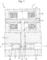
Figure 1 shows an example of a prior art servo valve; -
Figure 2 shows another example of a prior art servo valve with contaminant filters; -
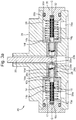
Figure 3a shows a cross-sectional view of an embodiment of a nozzle assembly of astage 1 servo valve assembly in accordance with this disclosure; -
Figure 3b shows a portion of the embodiment ofFigure 3a showing accumulation of contaminant particles in the nozzle assembly; -
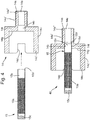
Figures 4 shows a cross-sectional view of the tubular filter in both an exploded and assembled state; and -
Figures 5a shows an enlarged cross-sectional view of part of the nozzle assembly ofFigure 3a ; -
Figure 5b shows a perspective view of the part shown inFigure 5b . - With reference to
Figure 1 , aservo valve 1 is illustrated.Servo valve 1 comprises anelectric motor 4, aflapper 2, axially aligned, opposednozzles 6 and anozzle housing 8. Theelectric motor 4 comprisescoils 4a,permanent magnets 4b and anarmature 4c. Thecoils 4a are in electrical communication with an electrical supply (not shown) and when activated, interact with thepermanent magnets 4b to create movement of thearmature 4c, as is well-known in the art. - The
flapper 2 is attached to thearmature 4c, and is deflected by movement of thearmature 4c. Thenozzles 6 are housed within nozzle cavities within thenozzle housing 8 via an interference fit and each comprises afluid outlet 6a and afluid inlet 6b. Thenozzle housing 8 also has a pair ofports 8a, which allow communication of fluid to thenozzles 6 from a fluid supply (not shown). - The
flapper 2 comprises ablocking element 2a at an end thereof which interacts with thefluid outlets 6a of thenozzles 6 to provide metering of fluid from thefluid outlets 6a to afluid port 8b in thenozzle housing 8, which allows communication of metered fluid from thenozzles 6 to an actuator (not shown). As is known in the art, theelectric motor 4 is used to control deflection of theblocking element 2a and vary the fluid delivered to the actuator from thenozzles 6 as required. - Calibration of the
servo valve 1 is achieved by adjusting the axial distance from thenozzle fluid outlet 6a to theflapper 2, by pulling or pushing thenozzles 6 axially (left or right inFigure 1 ) within thenozzle housing 8, parallel to the central longitudinal axis C-C of the nozzle cavity. - With reference to
Figure 2 , a priorart servo valve 1 is illustrated, which is similar to that shown inFigure 1 , but which further comprisescontaminant filters 9 positioned overfluid ports Servo valve 1 also further comprisescaps 10 thatseal nozzle cavities 12 from the environment (i.e. after calibration). To this end,caps 10 feature arecess 10a and O-ring 10b within the recess that provides a seal between thecap 10 and thenozzle housing 8. - With reference to
Figure 3a , anozzle assembly 20 of a servo valve, in accordance with the disclosure, is illustrated.Nozzle assembly 20 comprises anozzle housing 28 having anozzle cavity 21 therein, aflapper 22 with a blockingelement 22a, and axially aligned, opposednozzles 26 received in thenozzle cavity 21. Thenozzles 26 comprisenozzle outlets 26a,inlets 26b, and an inner threadedportion 26c, for example, at the inlet end of thenozzle 26.Nozzles 26 are secured in thenozzle cavity 21 and calibrated relative to the central longitudinal axis C-C of thenozzle cavity 21 in the same manner as described in relation toFigures 1 and2 above, by engaging a threaded calibration rod with the threadedportion 26c of thenozzle 26 and moving thenozzle 26 by pushing or pulling on the calibration rod. Thehousing 28 also has a pair ofports 28a, which allow communication of fluid to thenozzles 26, and afluid port 28b, which allows communication of metered fluid from thenozzles 26 to an actuator downstream (not shown). - With reference to
Figures 3a ,4 ,5a and5b , atubular filter 40 is received in thenozzle cavity 21. As will be appreciated by one skilled in the art, "tubular" is not limited to a tube of circular cross-section (i.e. cylindrical tube), but also includes a tube of any suitable cross-section, for instance, a square/rectangle cross-section tube or an oval cross-section tube. - In this embodiment, the
tubular filter 40 comprises anozzle fitting adapter 14 and atubular filter body 15.Nozzle fitting adapter 14 comprises radially inner and outercylindrical portions cylindrical portion 14a comprises a threadedportion 14a' on itsexternal surface 14a", a filter bodyfitting region 14b, and anoutlet 14e. The radially outercylindrical portion 14c comprises anouter collar portion 14c' and opposedslots 14d formed in the end surface of thecollar portion 14c'. The radially inner and outercylindrical portions shoulder portion 14f. In this embodiment, theadapter 14 is formed as a unitary, monolithic component. - In this embodiment, the
tubular filter body 15 comprises amesh 15a (i.e. perforated surface), afirst end 15b, and an opposingsecond end 15c. Thetubular filter 40 is assembled (as shown inFigure 4 ) by receiving thefirst end 15b into the bodyfitting region 14b and fixing them together to form joint 15d by one or more of interference fitting, welding, or brazing, for example. To improve the attachment of thefilter body 15 to thenozzle 26, thefirst end 15b of thefilter body 15 is non-perforated, i.e. has a circumferentiallysolid wall 15b'. Thefirst end 15b may, as shown, project beyond theshoulder portion 14f of theadapter 14, into a portion of the bodyfitting region 14b which has a larger inner diameter than the radially innercylindrical portion 14a. -
Tubular filter 40 is threadably attached to thenozzle 26, at thenozzle inlet 26b, by threaded engagement between the threadedportion 14a' of thenozzle fitting adapter 14 and the inner threadedportion 26c of thenozzle 26, which are complementarily threaded. - The plurality of
slots 14d in thecollar portion 14c of thenozzle fitting adapter 14 are configured to receive a torque tool, which can be used to aid threaded insertion and removal of thetubular filter 40 from thenozzles 26. - As shown in
Figure 3b , themesh 15a is configured to block (i.e. filter out) contaminant particles CON from entering thetubular filter 40 and thus passing through to thenozzles 26. In this manner,mesh 15a comprises openings of a size appropriate to block contaminant particles CON of a certain maximum size. As will be appreciated by the skilled person, this size is known as the "absolute filtration" of themesh 15a. In a particular embodiment,mesh 15a comprises an absolute filtration of about 0.1 mm, however, any suitable absolute filtration/opening size can be used within the scope of this disclosure. - In certain applications, the nozzle assembly will be subject to high fluid pressures and/or temperatures. In these applications,
mesh 15a is to be made of a relatively durable/corrosion resistance material, for instance, in certain embodiments mesh 15a may be made of a 300 series stainless steel. - A
spring member 17 is placed into thenozzle cavity 21, around thefilter body 15 and placed into an abutting relationship with the axially facinginternal wall 14g ofnozzle fitting adapter 14. As shown inFigures 3a ,3b ,5a and5b , thespring member 17 is surrounded by thecollar portion 14c', which may help support placement of thespring member 17. In alternative embodiments, however, acollar portion 14c may not be necessary, and thespring member 17 can rest directly against thenozzle housing 28 in thecavity 21. - A
cap 30 is used to seal thenozzle cavity 21 from the environment.Cap 30 comprises aseal recess 30a holding O-ring 30b,attachment wings 30c,fastener apertures 30d and a filterbody receiving recess 32.Cap 30 is placed into thenozzle cavity 21 and secured to thenozzle housing 28 using removable fasteners (not shown) which pass through theapertures 30d in theattachment wings 30c. - The
second end 15c of thefilter body 15 is received and supported by the filterbody receiving recess 32. To provide improved connection, thesecond end 14c may also be solid (as shown), as opposed to perforated, although this is not essential. Having a solid end wall atsecond end 15c may also avoid the possibility of contaminants entering thefilter 40 orfilter body 15 through thesecond end 15c. - In this manner, the
filter body 15 is supported at both itsends tubular filter 40. In addition, thecap 30 abuts and compresses thespring member 17 between thenozzle fitting adapter 14 and thecap 30. The spring compression exerts a spring force on thenozzle fitting adapter 14, which opposes rotation of thenozzle fitting adapter 14. Theseal recess 30a and O-ring 30b provide a seal between thenozzle housing 28 and thecap 30, to prevent fluid exiting thehousing 28. - As shown in
Figure 3b , providing atubular filter body 15 immediately upstream of thenozzles 26 in a servo valve can provide amesh 15a with a relatively large filter flow area (i.e. compared to thefilters 9 shown in the example ofFigure 2 ). This can allow substantial accumulation of contaminant particles CON on themesh 15a, without causing a blockage, which may increase the operation time betweentubular filter 40 replacements. The nozzle-based location of thefilter body 15 also shortens the distance between themesh 15a and thenozzle outlet 26a compared to other prior art servo valve filter designs (such as shown inFigure 2 ). This gives less chance of contaminant particles being picked up downstream of thefilter body 15 and being transferred to thenozzle outlet 26a. - The
tubular filter 40 and its threaded attachment to thenozzle 26, vianozzle fitting adapter 14, provides a convenient modular filter solution that can be easily replaced. In addition, the filter can be fitted at the same time as nozzle calibration, which reduces overall servo valve assembly maintenance times. - Although the depicted embodiments include a
tubular filter 40 comprising atubular filter body 15 and anozzle fitting adapter 14, in alternative embodiments within the scope of this disclosure, thetubular filter body 15 may be connected to the nozzle directly, without the need for anozzle fitting adapter 14. In one of these alternative embodiments, thefirst end 15b may have a threaded portion that cooperates with thethread portion 26c of thenozzle 26 to provide connection to thenozzle 26. Also, in these alternative and other embodiments, it may be possible to dispense with supporting thesecond end 15c of thefilter body 15 in thecap 30.
Claims (15)
- A nozzle assembly (20) for a servo valve comprising:a nozzle (26) including a nozzle inlet (26b) and a nozzle outlet (26a); anda tubular filter (40) mounted to the nozzle (26) configured to filter fluid flowing into the nozzle (26) through the nozzle inlet (26b).
- The nozzle assembly of claim 1, wherein the tubular filter (40) comprises:a tubular filter body (15); anda nozzle fitting adapter (14);wherein a first end (15b) of the filter body (15) is fixed to the nozzle fitting adapter (14) and a portion of the nozzle fitting adapter (14) is received by a portion of the nozzle (26) at the nozzle inlet (26b).
- The nozzle assembly of claim 2, wherein the portions of the nozzle fitting adapter (14) and the nozzle inlet (26b) are complementary threaded portions (14a', 26c).
- The nozzle assembly of claim 2 or 3, wherein the nozzle assembly (20) further comprises:a housing (28) including a nozzle cavity (21), the nozzle (26) being received in the nozzle cavity (21); anda cap (30) receiving a second, opposing end (15c) of the filter body (15), and providing a removable seal between the environment and the nozzle cavity (21).
- The nozzle assembly of claim 4, wherein the cap (30) further comprises an annular recess (30a) and an O-ring (30b) received in the recess (30a).
- The nozzle assembly of claim 4 or 5, wherein the cap (30) is secured to the housing (28) with removable fasteners or via a screw thread on an outer surface of the cap (30) co-operating with a screw thread on the housing (28).
- The nozzle assembly of claim 4, 5 or 6, wherein the nozzle assembly (20) further comprises a spring member (17) extending between the cap (30) and the nozzle fitting adapter (14), the spring member (17) surrounding the filter body (15) and allowing fluid communication thereto.
- The nozzle assembly of any of claims 4 to 7, further comprising:a control fluid port opening (28a) into the nozzle cavity (21) and in fluid communication with the nozzle (26) via the tubular filter (40);a flapper arm (22) mounted opposite to the nozzle outlet (26a);an electric motor configured to control the distance between the flapper arm (22) relative to the nozzle outlet (26a).
- A tubular filter (40) for a nozzle assembly (20) of a servo valve comprising:a tubular filter body (15); anda nozzle fitting adapter (14);wherein a first end (15b) of the filter body (15) is fixed to the nozzle fitting adapter (14) and a portion (14a') of the nozzle fitting adapter (14) is threaded.
- The nozzle assembly or tubular filter of any of claims 2 to 9, wherein the nozzle fitting adapter (14) comprises a plurality of slots (14d) therein configured to receive a torque tool.
- The nozzle assembly or tubular filter of any of claims 2 to 10, wherein the first end (15b) of the filter body (15) is fixed to the nozzle fitting adapter (14) by one or more of an interference fit, weld or braze.
- The nozzle assembly or tubular filter of any preceding claim, wherein the tubular filter (40) comprises a mesh (15a) configured to provide an absolute filtration of around 0.1mm.
- A method of assembling a servo valve assembly comprising:providing a housing (28) including a nozzle cavity (21) having a central longitudinal axis (C);placing a nozzle (26) having a nozzle inlet (26b) and a nozzle outlet (26a) in the nozzle cavity (21);calibrating the nozzle (26) by moving the nozzle (26) in a direction parallel to the longitudinal axis (C);mounting a tubular filter (40) to the nozzle (26) configured to filter fluid flowing into the nozzle (26) through the nozzle inlet (26b).
- The method of claim 13, wherein the tubular filter (40) comprises:a tubular filter body (15); anda nozzle fitting adapter (14), wherein a first end (15b) of the filter body (15) is fixed to the nozzle fitting adapter (14); andthe step of mounting the tubular filter (40) to the nozzle (26) further comprises:mounting a portion of the nozzle fitting adapter (14) to a portion of the nozzle (26) at the nozzle inlet (26b).
- The method of claim 14, wherein the portion of the nozzle fitting adapter (14) is threaded; and
the step of mounting the tubular filter (40) to the nozzle (26) further comprises:threadably engaging the threaded portion (14a') of the nozzle fitting adapter (14) to the nozzle (26) at the nozzle inlet (26b).
Priority Applications (2)
| Application Number | Priority Date | Filing Date | Title |
|---|---|---|---|
| EP17461622.7A EP3473865B1 (en) | 2017-10-19 | 2017-10-19 | Nozzle assembly with filter for a servovalve |
| US16/117,055 US10821563B2 (en) | 2017-10-19 | 2018-08-30 | Nozzle assembly |
Applications Claiming Priority (1)
| Application Number | Priority Date | Filing Date | Title |
|---|---|---|---|
| EP17461622.7A EP3473865B1 (en) | 2017-10-19 | 2017-10-19 | Nozzle assembly with filter for a servovalve |
Publications (2)
| Publication Number | Publication Date |
|---|---|
| EP3473865A1 true EP3473865A1 (en) | 2019-04-24 |
| EP3473865B1 EP3473865B1 (en) | 2023-08-30 |
Family
ID=60191321
Family Applications (1)
| Application Number | Title | Priority Date | Filing Date |
|---|---|---|---|
| EP17461622.7A Active EP3473865B1 (en) | 2017-10-19 | 2017-10-19 | Nozzle assembly with filter for a servovalve |
Country Status (2)
| Country | Link |
|---|---|
| US (1) | US10821563B2 (en) |
| EP (1) | EP3473865B1 (en) |
Families Citing this family (4)
| Publication number | Priority date | Publication date | Assignee | Title |
|---|---|---|---|---|
| EP3517812B1 (en) * | 2018-01-30 | 2020-08-12 | Hamilton Sundstrand Corporation | Torque motor with double fix screws |
| EP3587832B1 (en) * | 2018-06-24 | 2024-04-03 | Hamilton Sundstrand Corporation | Servo valve housing |
| EP3715687B1 (en) * | 2019-03-29 | 2021-10-13 | Hamilton Sundstrand Corporation | Servo valves |
| EP3904700A1 (en) | 2020-04-28 | 2021-11-03 | Hamilton Sundstrand Corporation | A filter assembly for a servovalve |
Citations (5)
| Publication number | Priority date | Publication date | Assignee | Title |
|---|---|---|---|---|
| US2934765A (en) * | 1953-09-21 | 1960-04-26 | Ex Cell O Corp | Flow control servo valve |
| GB845109A (en) * | 1956-10-08 | 1960-08-17 | Moog Servocontrols Inc | Improvements in or relating to electrically operated servo valves |
| US3029830A (en) * | 1957-11-06 | 1962-04-17 | Garrett Corp | Servo valve |
| US3065145A (en) * | 1959-06-04 | 1962-11-20 | Gen Precision Inc | Straddle flapper controlled hydraulic valve |
| US6648014B1 (en) | 1999-09-01 | 2003-11-18 | Ebara Corporation | Fluid control valve and plate with filter |
Family Cites Families (13)
| Publication number | Priority date | Publication date | Assignee | Title |
|---|---|---|---|---|
| US2832318A (en) * | 1952-04-30 | 1958-04-29 | Ex Cell O Corp | Servo control unit |
| US3245424A (en) * | 1963-05-31 | 1966-04-12 | Olsen Zenny | Servo valve |
| GB1147204A (en) * | 1966-04-12 | 1969-04-02 | Zenny Olsen | Servo valve |
| US3584649A (en) * | 1969-06-13 | 1971-06-15 | Bell Aerospace Corp | Resiliently deformable interconnection between driven and driving members in servo valve |
| US3874405A (en) | 1973-08-24 | 1975-04-01 | Moog Inc | Multiple tow-stage electrohydraulic servovalve apparatus |
| US4378031A (en) * | 1979-05-22 | 1983-03-29 | Koehring Company | Electrohydraulic servovalve |
| US4352367A (en) * | 1980-07-18 | 1982-10-05 | Sundstrand Corporation | Electro-hydraulic control structure |
| US4592381A (en) * | 1984-02-07 | 1986-06-03 | Engineering Resources, Inc. | Multiple stage device for condensate removal from a steam piping system |
| CN2042903U (en) | 1988-10-15 | 1989-08-16 | 王万兴 | Antipollution high-flow electro-hydraulic servo valve |
| US6890139B2 (en) * | 2002-02-26 | 2005-05-10 | Phillips Screw Company | Fastener having recess useable with multiple drivers and method of manufacture |
| RU2241143C1 (en) | 2003-03-21 | 2004-11-27 | Открытое акционерное общество "Павловский машиностроительный завод ВОСХОД" | Electrohydraulic redundant servo drive |
| US9028686B2 (en) * | 2012-07-26 | 2015-05-12 | Bbb Industries, Llc | Internal magnetic filter for hydraulic systems |
| EP3205913B1 (en) * | 2016-02-11 | 2019-07-03 | Hamilton Sundstrand Corporation | Nozzle with changeable press fit |
-
2017
- 2017-10-19 EP EP17461622.7A patent/EP3473865B1/en active Active
-
2018
- 2018-08-30 US US16/117,055 patent/US10821563B2/en active Active
Patent Citations (5)
| Publication number | Priority date | Publication date | Assignee | Title |
|---|---|---|---|---|
| US2934765A (en) * | 1953-09-21 | 1960-04-26 | Ex Cell O Corp | Flow control servo valve |
| GB845109A (en) * | 1956-10-08 | 1960-08-17 | Moog Servocontrols Inc | Improvements in or relating to electrically operated servo valves |
| US3029830A (en) * | 1957-11-06 | 1962-04-17 | Garrett Corp | Servo valve |
| US3065145A (en) * | 1959-06-04 | 1962-11-20 | Gen Precision Inc | Straddle flapper controlled hydraulic valve |
| US6648014B1 (en) | 1999-09-01 | 2003-11-18 | Ebara Corporation | Fluid control valve and plate with filter |
Also Published As
| Publication number | Publication date |
|---|---|
| EP3473865B1 (en) | 2023-08-30 |
| US10821563B2 (en) | 2020-11-03 |
| US20190118315A1 (en) | 2019-04-25 |
Similar Documents
| Publication | Publication Date | Title |
|---|---|---|
| US10821563B2 (en) | Nozzle assembly | |
| US8911621B2 (en) | Filter screen and integrated valve with a filter screen | |
| EP2477750B1 (en) | Bayonet system for spray nozzles | |
| EP2954191B1 (en) | Valve for metering a fluid comprising a filter | |
| EP3004623B1 (en) | Filter for a fluid injection valve, fluid injection valve and method for producing a filter for a fluid injection valve | |
| US20150076052A1 (en) | Filter Assembly | |
| EP2275786A1 (en) | Device for preparing conditioned fluid flows | |
| EP2511783A2 (en) | Agricultural spraying overflow valve | |
| WO2018136410A1 (en) | Apparatuses and methods using high pressure dual check valve | |
| EP2086662B1 (en) | Filtering device | |
| KR20030036712A (en) | Fuel injection valve | |
| US20200261830A1 (en) | Filter | |
| WO2016122829A1 (en) | Injector inlet fuel screen | |
| EP3691769B1 (en) | Filter element with venting function for suspension on a filter head, and filter system | |
| US12048889B2 (en) | Filter assembly for a servovalve | |
| EP3587832B1 (en) | Servo valve housing | |
| EP3160614B1 (en) | Filter system and liquid filter | |
| GB2290486A (en) | Filter assemblies | |
| US11261986B2 (en) | Servo valve | |
| EP3773980A1 (en) | Filter element and filter assembly | |
| EP3414436B1 (en) | Exhaust gas outlet system for a motor vehicle, motor vehicle having such an exhaust gas outlet system, and method for producing an exhaust gas outlet system | |
| EP3660365B1 (en) | Servo valve | |
| CN114270047A (en) | Pneumatic fluid pump with dual rotary swirl cleaning action | |
| US20200025220A1 (en) | Servo valve | |
| EP3037650B1 (en) | Valve assembly and fluid injection valve |
Legal Events
| Date | Code | Title | Description |
|---|---|---|---|
| PUAI | Public reference made under article 153(3) epc to a published international application that has entered the european phase |
Free format text: ORIGINAL CODE: 0009012 |
|
| STAA | Information on the status of an ep patent application or granted ep patent |
Free format text: STATUS: THE APPLICATION HAS BEEN PUBLISHED |
|
| AK | Designated contracting states |
Kind code of ref document: A1 Designated state(s): AL AT BE BG CH CY CZ DE DK EE ES FI FR GB GR HR HU IE IS IT LI LT LU LV MC MK MT NL NO PL PT RO RS SE SI SK SM TR |
|
| AX | Request for extension of the european patent |
Extension state: BA ME |
|
| STAA | Information on the status of an ep patent application or granted ep patent |
Free format text: STATUS: REQUEST FOR EXAMINATION WAS MADE |
|
| 17P | Request for examination filed |
Effective date: 20191024 |
|
| RBV | Designated contracting states (corrected) |
Designated state(s): AL AT BE BG CH CY CZ DE DK EE ES FI FR GB GR HR HU IE IS IT LI LT LU LV MC MK MT NL NO PL PT RO RS SE SI SK SM TR |
|
| STAA | Information on the status of an ep patent application or granted ep patent |
Free format text: STATUS: EXAMINATION IS IN PROGRESS |
|
| 17Q | First examination report despatched |
Effective date: 20220609 |
|
| GRAP | Despatch of communication of intention to grant a patent |
Free format text: ORIGINAL CODE: EPIDOSNIGR1 |
|
| STAA | Information on the status of an ep patent application or granted ep patent |
Free format text: STATUS: GRANT OF PATENT IS INTENDED |
|
| INTG | Intention to grant announced |
Effective date: 20230309 |
|
| GRAS | Grant fee paid |
Free format text: ORIGINAL CODE: EPIDOSNIGR3 |
|
| GRAA | (expected) grant |
Free format text: ORIGINAL CODE: 0009210 |
|
| STAA | Information on the status of an ep patent application or granted ep patent |
Free format text: STATUS: THE PATENT HAS BEEN GRANTED |
|
| AK | Designated contracting states |
Kind code of ref document: B1 Designated state(s): AL AT BE BG CH CY CZ DE DK EE ES FI FR GB GR HR HU IE IS IT LI LT LU LV MC MK MT NL NO PL PT RO RS SE SI SK SM TR |
|
| REG | Reference to a national code |
Ref country code: GB Ref legal event code: FG4D |
|
| REG | Reference to a national code |
Ref country code: CH Ref legal event code: EP |
|
| REG | Reference to a national code |
Ref country code: DE Ref legal event code: R096 Ref document number: 602017073345 Country of ref document: DE |
|
| REG | Reference to a national code |
Ref country code: IE Ref legal event code: FG4D |
|
| REG | Reference to a national code |
Ref country code: LT Ref legal event code: MG9D |
|
| REG | Reference to a national code |
Ref country code: NL Ref legal event code: MP Effective date: 20230830 |
|
| REG | Reference to a national code |
Ref country code: AT Ref legal event code: MK05 Ref document number: 1605774 Country of ref document: AT Kind code of ref document: T Effective date: 20230830 |
|
| PG25 | Lapsed in a contracting state [announced via postgrant information from national office to epo] |
Ref country code: GR Free format text: LAPSE BECAUSE OF FAILURE TO SUBMIT A TRANSLATION OF THE DESCRIPTION OR TO PAY THE FEE WITHIN THE PRESCRIBED TIME-LIMIT Effective date: 20231201 |
|
| PG25 | Lapsed in a contracting state [announced via postgrant information from national office to epo] |
Ref country code: IS Free format text: LAPSE BECAUSE OF FAILURE TO SUBMIT A TRANSLATION OF THE DESCRIPTION OR TO PAY THE FEE WITHIN THE PRESCRIBED TIME-LIMIT Effective date: 20231230 |
|
| PG25 | Lapsed in a contracting state [announced via postgrant information from national office to epo] |
Ref country code: SE Free format text: LAPSE BECAUSE OF FAILURE TO SUBMIT A TRANSLATION OF THE DESCRIPTION OR TO PAY THE FEE WITHIN THE PRESCRIBED TIME-LIMIT Effective date: 20230830 Ref country code: RS Free format text: LAPSE BECAUSE OF FAILURE TO SUBMIT A TRANSLATION OF THE DESCRIPTION OR TO PAY THE FEE WITHIN THE PRESCRIBED TIME-LIMIT Effective date: 20230830 Ref country code: NO Free format text: LAPSE BECAUSE OF FAILURE TO SUBMIT A TRANSLATION OF THE DESCRIPTION OR TO PAY THE FEE WITHIN THE PRESCRIBED TIME-LIMIT Effective date: 20231130 Ref country code: LV Free format text: LAPSE BECAUSE OF FAILURE TO SUBMIT A TRANSLATION OF THE DESCRIPTION OR TO PAY THE FEE WITHIN THE PRESCRIBED TIME-LIMIT Effective date: 20230830 Ref country code: LT Free format text: LAPSE BECAUSE OF FAILURE TO SUBMIT A TRANSLATION OF THE DESCRIPTION OR TO PAY THE FEE WITHIN THE PRESCRIBED TIME-LIMIT Effective date: 20230830 Ref country code: IS Free format text: LAPSE BECAUSE OF FAILURE TO SUBMIT A TRANSLATION OF THE DESCRIPTION OR TO PAY THE FEE WITHIN THE PRESCRIBED TIME-LIMIT Effective date: 20231230 Ref country code: HR Free format text: LAPSE BECAUSE OF FAILURE TO SUBMIT A TRANSLATION OF THE DESCRIPTION OR TO PAY THE FEE WITHIN THE PRESCRIBED TIME-LIMIT Effective date: 20230830 Ref country code: GR Free format text: LAPSE BECAUSE OF FAILURE TO SUBMIT A TRANSLATION OF THE DESCRIPTION OR TO PAY THE FEE WITHIN THE PRESCRIBED TIME-LIMIT Effective date: 20231201 Ref country code: FI Free format text: LAPSE BECAUSE OF FAILURE TO SUBMIT A TRANSLATION OF THE DESCRIPTION OR TO PAY THE FEE WITHIN THE PRESCRIBED TIME-LIMIT Effective date: 20230830 Ref country code: AT Free format text: LAPSE BECAUSE OF FAILURE TO SUBMIT A TRANSLATION OF THE DESCRIPTION OR TO PAY THE FEE WITHIN THE PRESCRIBED TIME-LIMIT Effective date: 20230830 |
|
| PG25 | Lapsed in a contracting state [announced via postgrant information from national office to epo] |
Ref country code: PL Free format text: LAPSE BECAUSE OF FAILURE TO SUBMIT A TRANSLATION OF THE DESCRIPTION OR TO PAY THE FEE WITHIN THE PRESCRIBED TIME-LIMIT Effective date: 20230830 Ref country code: NL Free format text: LAPSE BECAUSE OF FAILURE TO SUBMIT A TRANSLATION OF THE DESCRIPTION OR TO PAY THE FEE WITHIN THE PRESCRIBED TIME-LIMIT Effective date: 20230830 |
|
| PG25 | Lapsed in a contracting state [announced via postgrant information from national office to epo] |
Ref country code: ES Free format text: LAPSE BECAUSE OF FAILURE TO SUBMIT A TRANSLATION OF THE DESCRIPTION OR TO PAY THE FEE WITHIN THE PRESCRIBED TIME-LIMIT Effective date: 20230830 |
|
| PG25 | Lapsed in a contracting state [announced via postgrant information from national office to epo] |
Ref country code: SM Free format text: LAPSE BECAUSE OF FAILURE TO SUBMIT A TRANSLATION OF THE DESCRIPTION OR TO PAY THE FEE WITHIN THE PRESCRIBED TIME-LIMIT Effective date: 20230830 Ref country code: RO Free format text: LAPSE BECAUSE OF FAILURE TO SUBMIT A TRANSLATION OF THE DESCRIPTION OR TO PAY THE FEE WITHIN THE PRESCRIBED TIME-LIMIT Effective date: 20230830 Ref country code: ES Free format text: LAPSE BECAUSE OF FAILURE TO SUBMIT A TRANSLATION OF THE DESCRIPTION OR TO PAY THE FEE WITHIN THE PRESCRIBED TIME-LIMIT Effective date: 20230830 Ref country code: EE Free format text: LAPSE BECAUSE OF FAILURE TO SUBMIT A TRANSLATION OF THE DESCRIPTION OR TO PAY THE FEE WITHIN THE PRESCRIBED TIME-LIMIT Effective date: 20230830 Ref country code: DK Free format text: LAPSE BECAUSE OF FAILURE TO SUBMIT A TRANSLATION OF THE DESCRIPTION OR TO PAY THE FEE WITHIN THE PRESCRIBED TIME-LIMIT Effective date: 20230830 Ref country code: CZ Free format text: LAPSE BECAUSE OF FAILURE TO SUBMIT A TRANSLATION OF THE DESCRIPTION OR TO PAY THE FEE WITHIN THE PRESCRIBED TIME-LIMIT Effective date: 20230830 Ref country code: PT Free format text: LAPSE BECAUSE OF FAILURE TO SUBMIT A TRANSLATION OF THE DESCRIPTION OR TO PAY THE FEE WITHIN THE PRESCRIBED TIME-LIMIT Effective date: 20240102 Ref country code: SK Free format text: LAPSE BECAUSE OF FAILURE TO SUBMIT A TRANSLATION OF THE DESCRIPTION OR TO PAY THE FEE WITHIN THE PRESCRIBED TIME-LIMIT Effective date: 20230830 |
|
| PG25 | Lapsed in a contracting state [announced via postgrant information from national office to epo] |
Ref country code: IT Free format text: LAPSE BECAUSE OF FAILURE TO SUBMIT A TRANSLATION OF THE DESCRIPTION OR TO PAY THE FEE WITHIN THE PRESCRIBED TIME-LIMIT Effective date: 20230830 Ref country code: MC Free format text: LAPSE BECAUSE OF FAILURE TO SUBMIT A TRANSLATION OF THE DESCRIPTION OR TO PAY THE FEE WITHIN THE PRESCRIBED TIME-LIMIT Effective date: 20230830 |
|
| REG | Reference to a national code |
Ref country code: CH Ref legal event code: PL |
|
| REG | Reference to a national code |
Ref country code: DE Ref legal event code: R097 Ref document number: 602017073345 Country of ref document: DE |
|
| REG | Reference to a national code |
Ref country code: BE Ref legal event code: MM Effective date: 20231031 |
|
| PG25 | Lapsed in a contracting state [announced via postgrant information from national office to epo] |
Ref country code: LU Free format text: LAPSE BECAUSE OF NON-PAYMENT OF DUE FEES Effective date: 20231019 |
|
| PG25 | Lapsed in a contracting state [announced via postgrant information from national office to epo] |
Ref country code: LU Free format text: LAPSE BECAUSE OF NON-PAYMENT OF DUE FEES Effective date: 20231019 |
|
| PLBE | No opposition filed within time limit |
Free format text: ORIGINAL CODE: 0009261 |
|
| STAA | Information on the status of an ep patent application or granted ep patent |
Free format text: STATUS: NO OPPOSITION FILED WITHIN TIME LIMIT |
|
| PG25 | Lapsed in a contracting state [announced via postgrant information from national office to epo] |
Ref country code: CH Free format text: LAPSE BECAUSE OF NON-PAYMENT OF DUE FEES Effective date: 20231031 |
|
| PG25 | Lapsed in a contracting state [announced via postgrant information from national office to epo] |
Ref country code: CH Free format text: LAPSE BECAUSE OF NON-PAYMENT OF DUE FEES Effective date: 20231031 Ref country code: SI Free format text: LAPSE BECAUSE OF FAILURE TO SUBMIT A TRANSLATION OF THE DESCRIPTION OR TO PAY THE FEE WITHIN THE PRESCRIBED TIME-LIMIT Effective date: 20230830 |
|
| 26N | No opposition filed |
Effective date: 20240603 |
|
| PG25 | Lapsed in a contracting state [announced via postgrant information from national office to epo] |
Ref country code: BE Free format text: LAPSE BECAUSE OF NON-PAYMENT OF DUE FEES Effective date: 20231031 |
|
| PG25 | Lapsed in a contracting state [announced via postgrant information from national office to epo] |
Ref country code: IE Free format text: LAPSE BECAUSE OF NON-PAYMENT OF DUE FEES Effective date: 20231019 |
|
| PG25 | Lapsed in a contracting state [announced via postgrant information from national office to epo] |
Ref country code: IE Free format text: LAPSE BECAUSE OF NON-PAYMENT OF DUE FEES Effective date: 20231019 |
|
| PG25 | Lapsed in a contracting state [announced via postgrant information from national office to epo] |
Ref country code: BG Free format text: LAPSE BECAUSE OF FAILURE TO SUBMIT A TRANSLATION OF THE DESCRIPTION OR TO PAY THE FEE WITHIN THE PRESCRIBED TIME-LIMIT Effective date: 20230830 |
|
| PG25 | Lapsed in a contracting state [announced via postgrant information from national office to epo] |
Ref country code: BG Free format text: LAPSE BECAUSE OF FAILURE TO SUBMIT A TRANSLATION OF THE DESCRIPTION OR TO PAY THE FEE WITHIN THE PRESCRIBED TIME-LIMIT Effective date: 20230830 |
|
| PG25 | Lapsed in a contracting state [announced via postgrant information from national office to epo] |
Ref country code: CY Free format text: LAPSE BECAUSE OF FAILURE TO SUBMIT A TRANSLATION OF THE DESCRIPTION OR TO PAY THE FEE WITHIN THE PRESCRIBED TIME-LIMIT; INVALID AB INITIO Effective date: 20171019 |
|
| PG25 | Lapsed in a contracting state [announced via postgrant information from national office to epo] |
Ref country code: HU Free format text: LAPSE BECAUSE OF FAILURE TO SUBMIT A TRANSLATION OF THE DESCRIPTION OR TO PAY THE FEE WITHIN THE PRESCRIBED TIME-LIMIT; INVALID AB INITIO Effective date: 20171019 |
|
| PGFP | Annual fee paid to national office [announced via postgrant information from national office to epo] |
Ref country code: GB Payment date: 20250923 Year of fee payment: 9 |
|
| PGFP | Annual fee paid to national office [announced via postgrant information from national office to epo] |
Ref country code: FR Payment date: 20250924 Year of fee payment: 9 |
|
| PG25 | Lapsed in a contracting state [announced via postgrant information from national office to epo] |
Ref country code: TR Free format text: LAPSE BECAUSE OF FAILURE TO SUBMIT A TRANSLATION OF THE DESCRIPTION OR TO PAY THE FEE WITHIN THE PRESCRIBED TIME-LIMIT Effective date: 20230830 |
|
| PGFP | Annual fee paid to national office [announced via postgrant information from national office to epo] |
Ref country code: DE Payment date: 20250923 Year of fee payment: 9 |
|
| P01 | Opt-out of the competence of the unified patent court (upc) registered |
Free format text: CASE NUMBER: UPC_APP_0017205_3473865/2025 Effective date: 20251211 |