EP3473850A1 - Method for determining arrangement position of vortex generator on wind turbine blade, method for producing wind turbine blade assembly, and wind turbine blade assembly - Google Patents
Method for determining arrangement position of vortex generator on wind turbine blade, method for producing wind turbine blade assembly, and wind turbine blade assembly Download PDFInfo
- Publication number
- EP3473850A1 EP3473850A1 EP18158411.1A EP18158411A EP3473850A1 EP 3473850 A1 EP3473850 A1 EP 3473850A1 EP 18158411 A EP18158411 A EP 18158411A EP 3473850 A1 EP3473850 A1 EP 3473850A1
- Authority
- EP
- European Patent Office
- Prior art keywords
- wind turbine
- blade
- vortex generator
- turbine blade
- fins
- Prior art date
- Legal status (The legal status is an assumption and is not a legal conclusion. Google has not performed a legal analysis and makes no representation as to the accuracy of the status listed.)
- Granted
Links
Images





Classifications
-
- F—MECHANICAL ENGINEERING; LIGHTING; HEATING; WEAPONS; BLASTING
- F03—MACHINES OR ENGINES FOR LIQUIDS; WIND, SPRING, OR WEIGHT MOTORS; PRODUCING MECHANICAL POWER OR A REACTIVE PROPULSIVE THRUST, NOT OTHERWISE PROVIDED FOR
- F03D—WIND MOTORS
- F03D1/00—Wind motors with rotation axis substantially parallel to the air flow entering the rotor
- F03D1/06—Rotors
- F03D1/0608—Rotors characterised by their aerodynamic shape
- F03D1/0633—Rotors characterised by their aerodynamic shape of the blades
-
- F—MECHANICAL ENGINEERING; LIGHTING; HEATING; WEAPONS; BLASTING
- F03—MACHINES OR ENGINES FOR LIQUIDS; WIND, SPRING, OR WEIGHT MOTORS; PRODUCING MECHANICAL POWER OR A REACTIVE PROPULSIVE THRUST, NOT OTHERWISE PROVIDED FOR
- F03D—WIND MOTORS
- F03D1/00—Wind motors with rotation axis substantially parallel to the air flow entering the rotor
- F03D1/06—Rotors
- F03D1/0608—Rotors characterised by their aerodynamic shape
- F03D1/0633—Rotors characterised by their aerodynamic shape of the blades
- F03D1/0641—Rotors characterised by their aerodynamic shape of the blades of the section profile of the blades, i.e. aerofoil profile
-
- F—MECHANICAL ENGINEERING; LIGHTING; HEATING; WEAPONS; BLASTING
- F05—INDEXING SCHEMES RELATING TO ENGINES OR PUMPS IN VARIOUS SUBCLASSES OF CLASSES F01-F04
- F05B—INDEXING SCHEME RELATING TO WIND, SPRING, WEIGHT, INERTIA OR LIKE MOTORS, TO MACHINES OR ENGINES FOR LIQUIDS COVERED BY SUBCLASSES F03B, F03D AND F03G
- F05B2240/00—Components
- F05B2240/20—Rotors
- F05B2240/30—Characteristics of rotor blades, i.e. of any element transforming dynamic fluid energy to or from rotational energy and being attached to a rotor
- F05B2240/306—Surface measures
- F05B2240/3062—Vortex generators
-
- F—MECHANICAL ENGINEERING; LIGHTING; HEATING; WEAPONS; BLASTING
- F05—INDEXING SCHEMES RELATING TO ENGINES OR PUMPS IN VARIOUS SUBCLASSES OF CLASSES F01-F04
- F05B—INDEXING SCHEME RELATING TO WIND, SPRING, WEIGHT, INERTIA OR LIKE MOTORS, TO MACHINES OR ENGINES FOR LIQUIDS COVERED BY SUBCLASSES F03B, F03D AND F03G
- F05B2240/00—Components
- F05B2240/20—Rotors
- F05B2240/30—Characteristics of rotor blades, i.e. of any element transforming dynamic fluid energy to or from rotational energy and being attached to a rotor
- F05B2240/32—Characteristics of rotor blades, i.e. of any element transforming dynamic fluid energy to or from rotational energy and being attached to a rotor with roughened surface
-
- Y—GENERAL TAGGING OF NEW TECHNOLOGICAL DEVELOPMENTS; GENERAL TAGGING OF CROSS-SECTIONAL TECHNOLOGIES SPANNING OVER SEVERAL SECTIONS OF THE IPC; TECHNICAL SUBJECTS COVERED BY FORMER USPC CROSS-REFERENCE ART COLLECTIONS [XRACs] AND DIGESTS
- Y02—TECHNOLOGIES OR APPLICATIONS FOR MITIGATION OR ADAPTATION AGAINST CLIMATE CHANGE
- Y02E—REDUCTION OF GREENHOUSE GAS [GHG] EMISSIONS, RELATED TO ENERGY GENERATION, TRANSMISSION OR DISTRIBUTION
- Y02E10/00—Energy generation through renewable energy sources
- Y02E10/70—Wind energy
- Y02E10/72—Wind turbines with rotation axis in wind direction
-
- Y—GENERAL TAGGING OF NEW TECHNOLOGICAL DEVELOPMENTS; GENERAL TAGGING OF CROSS-SECTIONAL TECHNOLOGIES SPANNING OVER SEVERAL SECTIONS OF THE IPC; TECHNICAL SUBJECTS COVERED BY FORMER USPC CROSS-REFERENCE ART COLLECTIONS [XRACs] AND DIGESTS
- Y02—TECHNOLOGIES OR APPLICATIONS FOR MITIGATION OR ADAPTATION AGAINST CLIMATE CHANGE
- Y02P—CLIMATE CHANGE MITIGATION TECHNOLOGIES IN THE PRODUCTION OR PROCESSING OF GOODS
- Y02P70/00—Climate change mitigation technologies in the production process for final industrial or consumer products
- Y02P70/50—Manufacturing or production processes characterised by the final manufactured product
Definitions
- curved convex shape refers to a shape that bulges in a direction away from the wind turbine blade 2 to have, at least partially, a bulged portion with a curved profile (the shape of the front surface 17 of the platform portion 11).
- the vortex generator 10 may include a pair of fins 12 disposed closer to the blade root 3 than the starting point 40 of the flat back of the wind turbine blade 2 (see FIG. 11 ).
- a method for determining arrangement of the vortex generator 10 to the wind turbine blade 2 includes: determining arrangement of the vortex generator to an angular position offset by a predetermined angle toward the trailing edge 7 of the wind turbine blade 2 with reference to an inflow angle of wind to the wind turbine blade 2, in the first region M in the blade spanwise direction L, of the mounting range of the vortex generator 10 to the wind turbine blade 2 (first step); determining an arrangement position of the vortex generator 10 between a separation position of a flow on the surface of the wind turbine blade 2 under a rated wind velocity condition and the transition position of a flow on the surface of the wind turbine blade 2 under a variable speed operation condition of a wind turbine including the wind turbine blade 2 (second step); and determining an arrangement condition of the vortex generator 10 by connecting the arrangements in the first step and the second step (third step).
- the origin O which is the reference of vectors and angles, is positioned at the center axis (pitch axis) of the blade root 3 of the wind turbine blade 2.
- the blade root 3 of the wind turbine blade 2 has a cylindrical shape, and the position of the center axis of the cylindrical shape (origin O) can be unambiguously defined on a cross section of the wind turbine blade 2 at each blade spanwise directional position.
- FIG. 14 is a graph showing an operational condition of a general wind turbine.
- FIG. 15A shows the cross section of the blade and a flow along the blade surface, under a variable speed operation condition in the second region N according to some embodiments.
- FIG. 15B shows the cross section of the blade and a flow along the blade surface, under a rated speed operation condition in the second region N according to some embodiments.
Landscapes
- Engineering & Computer Science (AREA)
- Mechanical Engineering (AREA)
- General Engineering & Computer Science (AREA)
- Physics & Mathematics (AREA)
- Fluid Mechanics (AREA)
- Life Sciences & Earth Sciences (AREA)
- Sustainable Development (AREA)
- Sustainable Energy (AREA)
- Chemical & Material Sciences (AREA)
- Combustion & Propulsion (AREA)
- Wind Motors (AREA)
Abstract
Description
- The present disclosure relates to a method for determining an arrangement position of a vortex generator on a wind turbine blade, a method for producing a wind turbine blade assembly, and a wind turbine blade assembly.
- Approaches to improve aerodynamic performance of a wind turbine blade have been sought for some time to improve operation efficiency of a wind turbine. In one of the approaches, a vortex generator (VG) is disposed on a surface of a wind turbine blade to suppress separation of a flow along the surface of the wind turbine blade.
-
Patent Document 1 discloses a vortex generator having a platform portion to be mounted to a surface of a wind turbine blade, and a fin disposed upright on the platform portion. - Patent Document 1:
EP2736805A - Meanwhile, in
Patent Document 1, the position of the vortex generator on the blade tip side is set in a region of 0.2 to 0.5L from the blade root side, with respect to the blade length L of the wind turbine blade. However, if the vortex generator is attached excessively, drag caused by the vortex generator, or drag penalty, may deteriorate the performance of the wind turbine blade. Thus, it is desirable to mount the vortex generator only to necessary locations. In this regard, a wind turbine blade in recent years has an improved aerodynamic performance and requires the vortex generator to be provided in a smaller region. Thus, mounting the vortex generator up to a region of 0.2 to 0.5L is not always the best arrangement. - In view of the above, an object of at least one embodiment of the present invention is to suppress occurrence of drag penalty caused by mounting a vortex generator.
- (1) A wind turbine blade according to at least one embodiment of the present invention comprises a vortex generator including a plurality of fins, wherein the plurality of fins include a first fin positioned closest to a blade tip, and the first fin is disposed closer to a blade root than a position closer to the blade tip, of a blade spanwise directional position at which a ratio t/C of a blade thickness 't' to a chord length C is 0.4 or a radial directional position of 0.2R with respect to a radius R of a rotor including the wind turbine blade.
As the size of a wind turbine blade increases, it is necessary to reduce the weight of the wind turbine blade. To reduce the weight of the wind turbine blade, it is effective to apply a great blade thickness ratio to the blade tip side of the wind turbine blade. As a result, the airfoil on the blade root side becomes relatively thin. In the region of 0.2R (r/R≤0.2) from the blade root of the above wind turbine blade, an airfoil having t/C of about 0.4 is applied. Separation is likely to occur in this region, for the wind inflow angle and the attack angle increase rapidly toward the blade root, and the blade thickness ratio is high. In this regard, with the above configuration (1), the mounting limit position of the first fin is set to be closer to the blade root than the position closer to the blade tip, of the blade spanwise directional position at which the blade thickness ratio t/C is 0.4, or the radial directional position of r/R≤0.2, which can be referred to as a region in which separation is likely to occur, and the vortex generator is disposed only at the blade-root side of the mounting limit position. Thus, it is possible to effectively suppress occurrence of drag penalty caused by mounting the vortex generator excessively, while enjoying the effect to suppress separation. - (2) In some embodiments, in the above configuration (1), the vortex generator includes at least one fin disposed in a mounting range of zero to 0.1 R, such that a ratio x/C of a chordwise directional position x of the at least one fin to the chord length C satisfies 0≤x/C≤0.2.
With the above configuration (2), it is possible to position the blade-root side starting point of the vortex generator in a region of zero to 0.1R in the blade spanwise direction and 0≤x/C≤0.2 in the chordwise direction. Accordingly, it is possible to obtain a wind turbine blade having the vortex generator capable of exerting the effect to reduce separation, in at least one of the rated wind velocity condition in the blade degradation state or the variable speed operation condition in the blade normal state. - (3) In some embodiments, in the above configuration (1) or (2), the vortex generator includes at least one fin disposed in a mounting range of 0.15 to 0.2R, such that a ratio x/C of a chordwise directional position x of the at least one fin to the chord length C satisfies 0.2≤x/C≤0.8.
With the above configuration (3), it is possible to position the blade-tip side terminating point of the vortex generator in a region of 0.15 to 0.2R in the blade spanwise direction, and 0.2≤x/C≤0.8 in the chordwise direction. Accordingly, it is possible to obtain the wind turbine blade having the vortex generator capable of exerting the effect to reduce separation, at least in the variable speed operation condition in the blade normal state. - (4) In some embodiments, in any one of the above configurations (1) to (3), the vortex generator may include a plurality of fin sets each of which is formed by a pair of fins each having a pressure surface and a suction surface, the fins being arranged such that the suction surfaces face each other. In the mounting range, a ratio Z/S of an arrangement pitch 'z' of two adjacent fin sets to an interval's' between trailing edges of the pair of fins may satisfy 1.5≤Z/S≤3.0.
To enhance the effect to suppress separation, it is desirable to arrange the vortex generator densely. On the other hand, to reduce drag, it is desirable to arrange the vortex generator less densely. Thus, as in the above configuration (4), by arranging the vortex generator with a density such that Z/S is not smaller than 1.5 and not greater than 3.0, it is possible to enjoy both of the effect to suppress separation and the effect to reduce drag at the same time. - (5) In some embodiments, in any one of the above configurations (1) to (4), the vortex generator may include a plurality of fin sets each of which is formed by a pair of fins arranged such that suction surfaces face each other, and a ratio S/H of an interval S between trailing edges of the pair of fins to a height H of the fins may satisfy 2.5≤S/H≤5.0.
As S/H decreases, the interval between the generated longitudinal vortices decreases, and mutual interference among the longitudinal vortices may cause reduction of the effect to suppress separation. In addition, an increased number of fins may increase drag of the vortex generator itself. On the other hand, as S/H increases, the interval between the generated longitudinal vortices increases. In this case, there are many locations without any longitudinal vortex in the mounting range of the vortex generator on the wind turbine blade, which may be a cause of reduction of the effect to suppress separation. Thus, as in the above (5), with S/H satisfying 2.5≤S/H≤5.0, it is possible to effectively enjoy the technical benefit from provision of the vortex generator. - (6) In some embodiments, in any one of the above configurations (1) to (5), the vortex generator may include a pair of fins arranged line-symmetrically with respect to a segment along a chordwise direction of the wind turbine blade.
With the above configuration (6), it is possible to arrange the vortex generator in an appropriate direction with respect to the inflow direction of wind, and to stabilize generation of vortices by the vortex generator. - (7) In some embodiments, in any one of the above configurations (1) to (6), the vortex generator may include a pair of fins arranged closer to the blade root than a starting point of a flat back of the wind turbine blade.
In a region close to the blade root, a flat back airfoil may be adopted to provide the trailing edge with a greater thickness, so as to suppress separation and maintain lift to a high attack angle. In contrast, in a region closer to the blade tip than the starting point of the flat back, separation is less likely to occur. If the vortex generator is arranged in this region, the demerit of occurrence of drag penalty may dominate. In this regard, with the above configuration (7), a pair of fins disposed closer to the blade root than the starting point of the flat back is included, and thus it is possible to effectively suppress occurrence of drag penalty caused by mounting the vortex generator excessively while enjoying the effect to suppress separation. - (8) In some embodiments, in any one of the above configurations (1) to (7), the vortex generator may include a plurality of fin sets each of which is formed by a pair of fins each having a pressure surface and a suction surface, the fins being arranged such that the suction surfaces face each other, and a ratio z/h of an arrangement pitch 'z' of the two adjacent fin sets to a height 'h' of the fins is not smaller than 6.0 and not greater than 8.0.
As described above (4), to enhance the effect to suppress separation, it is desirable to arrange the vortex generator densely. On the other hand, as the interval between adjacent fin sets decreases, the effect to suppress separation may reduce due to mutual interference among the generated longitudinal vortices. Thus, as in the above configuration (8), by arranging the vortex generator such that Z/H is not smaller than 6.0 and not greater than 8.0, it is possible to enjoy the effect to suppress separation and the effect to reduce drag at the same time. - (9) In some embodiments, in any one of the above configurations (1) to (8), a blade length L of the wind turbine blade satisfies L≥55m.
With the arrangement of the vortex generator described in the above (1), a higher effect can be achieved if a wind turbine blade has a greater blade length. In this regard, with the above configuration (9), the wind turbine blade having a blade length L that satisfies L≥55m can achieve the effect described in the above (1). Thus it is possible to suppress occurrence of drag penalty caused by mounting the vortex generator, for a wind turbine blade of a wind turbine of a relatively large size. - (10) In some embodiments, in any one of the above configurations (1) to (9), the vortex generator is disposed within a range where a blade thickness ratio is higher than 2×(t/c)ref, provided that (t/c)ref is a blade thickness ratio at a position where a ratio r/R of a blade spanwise directional position 'r' of the vortex generator to a radius R of the rotor is 0.8.
In recent years, it is necessary to reduce the weight of the wind turbine blade due to an increase in the size of the wind turbine blade. Thus, a greater blade thickness ratio may be applied to the blade tip side to adopt an airfoil in which the blade thickness ratio on the blade root side is relatively small. In such a case, provided that (t/c)ref is a blade thickness ratio at a position where r/R is 0.8, a region on the blade root side satisfying 2×(t/c)ref≤t/c may be regarded as a guide for the boundary of the region in which separation may occur. Thus, with the above configuration (10), it is possible to arrange the minimum vortex generator only in a region where separation is likely to occur, and thereby it is possible to effectively suppress occurrence of drag penalty caused by mounting the vortex generator excessively, while enjoying the effect to suppress separation. - (11) In some embodiments, in any one of the above configurations (1) to (10), the vortex generator is disposed in a range where a blade thickness ratio is not greater than 3×(t/c)ref, provided that (t/c)ref is a blade thickness ratio at a position where a ratio r/R of a blade spanwise directional position 'r' of the vortex generator to a radius R of the rotor is 0.8.
As described above, due to an increase in the size of the wind turbine blade, a greater blade thickness ratio may be applied to the blade tip side to adopt an airfoil in which the blade thickness ratio on the blade root side is relatively small. That is, the blade thickness ratio at r/R=0.2 with respect to the blade thickness ratio at r/R=0.8 in the wind turbine blade having an airfoil for a large wind turbine is smaller than that in a wind turbine blade having a typical airfoil (normally, about three times), and the region where the blade thickness ratio at r/R=0.2 is three times the blade thickness ratio at r/R=0.8 is a region on the side of the blade root satisfying r/R≤0.2, and can be regarded as a guide for the boundary of a region in which separation occurs. Thus, with the above configuration (11), it is possible to arrange the vortex generator only in a region where separation is likely to occur, and thereby it is possible to effectively suppress occurrence of drag penalty caused by mounting the vortex generator excessively, while enjoying the effect to suppress separation. - (12) A method for determining arrangement of a vortex generator including a plurality of fins on a wind turbine blade, according to at least one embodiment of the present invention, comprises: determining arrangement of the plurality of fins such that a first fin positioned closest to a blade tip, of the plurality of fins, is disposed closer to a blade root than a position closer to the blade tip, of a blade spanwise directional position at which a ratio t/C of a blade thickness 't' to a chord length C is 0.4 or a radial directional position of 0.2R with respect to a radius R of a rotor including the wind turbine blade.
According to the above method (12), as described above in (1), it is possible to determine the mounting limit position of the first fin to be closer to the blade root than the position closer to the blade tip, of the blade spanwise directional position at which the blade thickness ratio t/C is 0.4, or the radial directional position of r/R≤0.2, which can be referred to as a guide for a region in which separation is likely to occur, and thevortex generator 10 is disposed only at the blade-root side of the mounting limit position. Thus, it is possible to effectively suppress occurrence of drag penalty caused by mounting the vortex generator excessively, while enjoying the effect to suppress separation. - (13) A method for determining arrangement of a vortex generator on a wind turbine blade, according to at least one embodiment of the present invention, comprises: a first step of determining arrangement of the vortex generator at an angular position offset by a predetermined angle toward a trailing edge of the wind turbine blade, with reference to an inflow angle of wind to the wind turbine blade, in a first region, in a blade spanwise direction, of a mounting range of the vortex generator on the wind turbine blade; a second step of determining an arrangement position of the vortex generator between a separation position of a flow on a surface of the wind turbine blade under a rated wind speed condition and a transition position of a flow on the surface of the wind turbine blade under a variable speed operation condition of a wind turbine which includes the wind turbine blade, in a second region closer to a blade tip than the first region, of the mounting range; and a third step of determining the arrangement position of the vortex generator by connecting arrangements in the first step and the second step.
According to the above method (13), in the first step, it is possible to set the starting point of the arrangement of the vortex generator in the first region on the side of the blade root, at a position offset by a predetermined angle toward the trailing edge with reference to the inflow angle of wind. Furthermore, with the second step, it is possible to determine the terminating point of the arrangement of the vortex generator on the side of the blade tip at a position between the separation position of a flow on the surface of the wind turbine blade under a rated wind speed condition and the transition position of a flow on the surface of the wind turbine blade under a variable speed operation condition of a wind turbine including the wind turbine blade. Then, the arrangement is determined in the third step so as to connect the respective arrangements of the vortex generator determined in the first step and the second step, and thereby it is possible to arrange the vortex generator easily at a position where the vortex generator can exert its effect under both of the rated wind speed condition in the blade degradation state and the variable speed operation condition in the blade normal state. - (14) A method for producing a wind turbine blade assembly, according to at least one embodiment of the present invention, comprises a step of arranging the vortex generator on the wind turbine blade, according to any one of the above (1) to (11).
- With the above configuration (14), it is possible to obtain a wind turbine blade assembly provided with the vortex generator having the effect described in any one of the above (1) to (11).
- According to some embodiments of the present invention, it is possible to suppress occurrence of drag penalty caused by mounting a vortex generator.
-
-
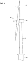
FIG. 1 is a schematic configuration diagram of a wind turbine power generating apparatus according to an embodiment. -
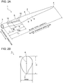
FIG. 2A is a perspective view of a wind turbine blade assembly according to an embodiment.FIG. 2B is a cross sectional view of a wind turbine blade assembly shown inFIG. 2A . -
FIG. 3 is a perspective view for describing a flow around the fin of a vortex generator according to an embodiment. -
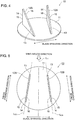
FIG. 4 is a perspective view of a vortex generator according to an embodiment. -
FIG. 5 is a top view of a vortex generator according to an embodiment. -
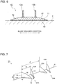
FIG. 6 is a cross-sectional view of a vortex generator according to an embodiment, taken along the blade spanwise direction. -
FIG. 7 is a perspective view of a vortex generator according to an embodiment. -
FIG. 8 is a graph showing a relationship between the radial directional position and the blade thickness ratio of a typical wind turbine blade. -
FIG. 9 is a graph showing a distribution of the blade spanwise directional position and the chordwise directional position of a typical vortex generator. -
FIG. 10 is a graph showing a distribution of the blade spanwise directional position and the chordwise directional position of a typical vortex generator. -
FIG. 11 is a perspective view of a wind turbine blade according to an embodiment. -
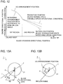
FIG. 12 is a graph showing an arrangement position of a vortex generator in the first region and the second region according to an embodiment. -
FIG. 13A is a cross sectional view of the wind turbine blade in the first region.FIG. 13B is a diagram showing an arrangement angle of a vortex generator in the first region according to an embodiment. -
FIGs. 14A to 14D are diagrams showing general operation conditions of a wind turbine. -
FIG. 14A is a graph showing a relationship between upstream wind velocity and rotation speed of a wind turbine.FIG. 14B is a graph showing a relationship between upstream wind velocity and tip speed ratio.FIG. 14C is a graph showing a relationship between upstream wind velocity and wind turbine output.FIG. 14D is a graph showing a relationship between upstream wind velocity and attack angle. -
FIGs. 15A and 15B are cross-sectional diagrams of a wind turbine blade assembly according to an embodiment.FIG. 15A is a diagram showing a transition position and a separation position under a variable speed operation condition.FIG. 15B is a diagram showing a transition position and a separation position under a variable speed operation condition. -
FIG. 16 is a planar view and a cross-sectional view of a wind turbine blade according to an embodiment. -
FIG. 17 is a graph showing a relationship between the chordwise directional position and the boundary layer thickness. -
FIGs. 18A and 18B are cross-sectional diagrams of a wind turbine blade according to an embodiment.FIG. 18A is a cross-sectional view of the blade root side, andFIG. 18B is a cross-sectional view of the blade tip side. -
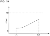
FIG. 19 is a graph showing a relationship between the radial directional position from the blade root and the mounting angle according to an embodiment. - Embodiments of the present invention will now be described in detail with reference to the accompanying drawings. It is intended, however, that unless particularly specified, dimensions, materials, shapes, relative positions and the like of components described in the embodiments shall be interpreted as illustrative only and not intended to limit the scope of the present invention.
- For instance, an expression of relative or absolute arrangement such as "in a direction", "along a direction", "parallel", "orthogonal", "centered", "concentric" and "coaxial" shall not be construed as indicating only the arrangement in a strict literal sense, but also includes a state where the arrangement is relatively displaced by a tolerance, or by an angle or a distance whereby it is possible to achieve the same function.
- For instance, an expression of an equal state such as "same" "equal" and "uniform" shall not be construed as indicating only the state in which the feature is strictly equal, but also includes a state in which there is a tolerance or a difference that can still achieve the same function.
- Further, for instance, an expression of a shape such as a rectangular shape or a cylindrical shape shall not be construed as only the geometrically strict shape, but also includes a shape with unevenness or chamfered corners within the range in which the same effect can be achieved.
- On the other hand, an expression such as "comprise", "include", "have", "contain" and "constitute" are not intended to be exclusive of other components.
- With reference to
FIGs. 1 and2A , overall configuration of a wind turbine blade and a wind turbine power generating apparatus to which a vortex generator according to some embodiments is to be applied will be described.FIG. 1 is a schematic configuration diagram of a wind turbine power generating apparatus according to an embodiment.FIG. 2A is a perspective view of a wind turbine blade to which a method for determining an arrangement position of a vortex generator according to an embodiment is to be applied. - As shown in
FIG. 1 , a wind turbinepower generating apparatus 90 includes at least one (e.g. three) windturbine blade assemblies 1. The windturbine blade assemblies 1 include awind turbine blade 2 and avortex generator 10. The windturbine blade assemblies 1 are mounted to ahub 94 in a radial fashion, and the windturbine blade assemblies 1 and thehub 94 constitute arotor 93 of the wind turbinepower generating apparatus 90. Therotor 93 rotates in response to wind received by the windturbine blade assemblies 1, and a generator (not depicted) coupled to therotor 93 generates electric power. - In the embodiment depicted in
FIG. 1 , therotor 93 is supported by anacelle 95 disposed on an upper part of atower 96. Thetower 96 is disposed to stand upright on a base structure 97 (e.g. foundation structure or floating structure) disposed on water or on land. - As described below, according to a method for determining an arrangement position of a vortex generator according to an embodiment, a
vortex generator 10 is mounted to thewind turbine blade 2 of thewind turbine assemblies 1, in the wind turbinepower generating apparatus 90 having the above configuration. - As shown in
FIG. 2A , the windturbine blade assembly 1 includes awind turbine blade 2. According to a method for determining an arrangement position according to an embodiment, thevortex generator 10 is arranged on the surface (blade surface) of thewind turbine blade 2. InFIG. 2A , thevortex generator 10 is already mounted to the windturbine blade assembly 1. - The
wind turbine blade 2 includes ablade root 3 to be attached to thehub 94 of the wind turbinepower generating apparatus 90, ablade tip 4 positioned farthest from thehub 94, and anairfoil part 5 extending between theblade root 3 and theblade tip 4. Thewind turbine blade 2 has aleading edge 6 and a trailingedge 7 from theblade root 3 to theblade tip 4. Further, an exterior shape of thewind turbine blade 2 is formed by apressure surface 8 and asuction surface 9 disposed opposite to thepressure surface 8. - As shown in
FIG. 2A , in the windturbine blade assembly 1, a plurality of thevortex generators 10 are mounted to thesuction surface 9 of thewind turbine blade 2. Furthermore, the plurality ofvortex generators 10 are mounted to thesuction surface 9 of thewind turbine blade 2 in a blade spanwise direction. - Hereinafter, "blade spanwise direction" refers to a direction connecting the
blade root 3 and theblade tip 4, and "blade chordwise direction" refers to a direction along a line (chord) connecting theleading edge 6 and the trailingedge 7 of the wind turbine blade 2 (hereinafter, also referred to as merely chordwise direction). - An aerodynamic function of the
vortex generator 10 will now be described briefly.FIG. 3 is a perspective view for describing function of thevortex generator 10. InFIG. 3 , only a pair ofadjacent fins fins vortex generators 10 shown inFIGs. 4 and 5 described below, in the blade spanwise direction of thewind turbine blade 2. - Separation of a flow at the
suction surface 9 of thewind turbine blade 2 takes place due to a boundary layer becoming gradually thicker from a streamline flow region in the vicinity of theleading edge 6 toward a turbulent flow region downstream thereof, and the flow being separated before arriving at the trailingedge 7. - As shown in
FIG. 3 , thevortex generator 10 mounted to thewind turbine blade 2 normally generates alongitudinal vortex 24 on the side of thesuction surface 16 of thefin 12 with a lift produced by thefin 12. Thelongitudinal vortex 24 promotes momentum exchange between outside and inside of aboundary layer 31 at a wake-flow side of thefin 12. Accordingly, in the region between the suction surfaces 16 of theadjacent fins 12, the thickness D of theboundary layer 31 of wake of thefins 12 decreases. Thus, with the plurality offins 12 arranged in the blade spanwise direction, theboundary layer 31 at the surface of thewind turbine blade 2 becomes thin as a whole, which suppresses trailing edge separation of thewind turbine blade 2. - It should be noted that
longitudinal vortices 24 refer to vortices formed in the height direction of thefins 12. - Next, the configuration the
vortex generator 10 will be described in detail with reference toFIGs. 4 to 7 .FIG. 4 is a perspective view of a vortex generator according to an embodiment.FIG. 5 is a top view of a vortex generator according to an embodiment.FIG. 6 is a cross-sectional view of a vortex generator according to an embodiment, taken along the blade spanwise direction.FIG. 7 is a perspective view of a vortex generator according to an embodiment. - As shown in
FIG. 4 , thevortex generator 10 according to some embodiments includes aplatform portion 11 fixed to a surface of the wind turbine 2 (more specifically, to a surface of the blade body 2) and at least onefin 12 disposed upright on theplatform portion 11. In the embodiment shown inFIGs. 4 to 6 , thevortex generator 10 includes a pair (two in total) of fins 12 (12A, 12B) disposed so as to be adjacent to each other on theplatform portion 11. - In the embodiment shown in
FIGs. 4 and 5 , theplatform portion 11 has a circular shape in a top view. - In some embodiments, the
platform portion 11 may have a shape other than a circular shape. For instance, theplatform portion 11 may have an oval shape, or a polygonal shape such as a rectangular shape. - Furthermore, as shown in
FIG. 7 as an example, in some embodiments, thevortex generator 10 may not necessarily include theplatform portion 11, and thefin 12 may be directly mounted to thewind turbine blade 2. - In some embodiments, as shown in
FIG. 5 , thefin 12 is disposed on thewind turbine blade 2 such that the extension lines LCA and LCB of the fin chords form a predetermined angle with the line LH along the chordwise direction of thewind turbine blade 2. - In
FIG. 5 , each of thefins fins leading edge 6 toward the side of the trailingedge 7 of the wind turbine blade 2 (seeFIG. 2 ), in a state where thevortex generator 10 is being mounted to the wind turbine blade 2). - In some embodiments, each of the
fins fins edge 7 toward the side of theleading edge 6 of the wind turbine blade 2 (seeFIG. 2 ) in a state where thevortex generator 10 is mounted to the wind turbine blade 2). - Furthermore, in an embodiment, the
fins 12 may be disposed on thewind turbine blade 2 such that the line LH along the chordwise direction of thewind turbine blade 2 bisects the angle formed by the extension lines LCA and LCB of a pair of fin chords. In some embodiments, thevortex generator 10 may include a pair offins 12 disposed line-symmetrically with respect to a segment along the chordwise direction C of thewind turbine blade 2. - As described above, with reference to the chord of the
wind turbine blade 2 along the wind inflow direction, thevortex generator 10 is arranged at an angle with respect to the fin chord. Accordingly, it is possible to mount thevortex generator 10 to thewind turbine blade 2 in a mounting direction suitable to enhance the effect to suppress separation, with respect to the wind inflow direction. - In
FIG. 6 , depicted is across section 19 of theplatform portion 11 of thevortex generator 10 taken along the blade spanwise direction. As shown inFIG. 6 , in thevortex generator 10 according to some embodiments, theplatform portion 11 has afront surface 17 exposed to outside, and aback surface 18 opposite to the front surface of thewind turbine blade 2. As shown inFIG. 6 , in some embodiments, thevortex generator 10 is arranged on thewind turbine blade 2 while being oriented such that the cross sectional shape of theplatform portion 11 has a curved convex shape along the blade spanwise direction. - Herein, "curved convex shape" refers to a shape that bulges in a direction away from the
wind turbine blade 2 to have, at least partially, a bulged portion with a curved profile (the shape of thefront surface 17 of the platform portion 11). - The profile of the bulged portion may be formed by an arc having a single curvature radius as in the embodiment depicted in
FIG. 6 , or may be formed by combination of a plurality of arcs having different curvature radii, or combination of arcs having one or more curvature radii and one or more straight lines, in another non-depicted embodiment. - During operation of the wind turbine
power generating apparatus 90, thewind turbine blade 2 deforms flexurally due to bending deformation caused by an aerodynamic load. Thus, a great stress is applied to theplatform portion 11 of thevortex generator 10 mounted to the surface of thewind turbine blade 2. In this regard, with the above embodiment, theplatform portion 11 of thevortex generator 10 has a cross section of a curved convex shape along the blade spanwise direction of thewind turbine blade 2, and thereby the platform portion is deformable in accordance with bending deformation of thewind turbine blade 2, which makes it possible to disperse stress generated at theplatform portion 11. -
FIG. 7 is a perspective view of thevortex generator 10 mounted to thewind turbine blade 2. As shown inFIG. 7 , thevortex generator 10 according to some embodiments includes a plurality of fin sets 25 each formed by a pair of fins (12A, 12B), the fins each having apressure surface 15 and asuction surface 16 and being arranged such that the respective suction surfaces 16 face each other. In some embodiments, thevortex generator 10 is arranged such that a ratio Z/S of the arrangement pitch 'z' of the adjacent fin sets (25A, 25B) to the interval's' of the trailingedges 14 of the pair of fins (12A, 12B) is not smaller than 1.5 and not greater than 3.0. - To enhance the effect to suppress separation, it is desirable to arrange the
vortex generator 10 densely. On the other hand, to reduce drag, it is desirable to arrange thevortex generators 10 less densely. Thus, by arranging thevortex generators 10 with a density such that Z/S is not smaller than 1.5 and not greater than 3.0 as described above, it is possible to achieve both of the effect to suppress separation and the effect to reduce drag at the same time. - In some embodiments, a ratio S/H of the interval's' between the trailing edges of a pair of
fins 12 to the height 'h' of thefins 12 satisfies 2.5≤S/H≤5.0 (seeFIG. 7 ). - S/H is a value related to the distance between the trailing edges of a pair of
fins 12. As S/H decreases, the distance between longitudinal vortices 29 generated on the side of the trailingedges 14 of thefins 12 also decreases. Thus, the longitudinal vortices 29 may interfere with each other, thereby reducing the effect to suppress separation. In addition, as S/H decreases, the number of thefins 12 in the mounting region of thevortex generator 10 on thewind turbine blade 2 increases. Thus, the drag of thevortex generator 10 itself increases, which may cause occurrence of drag penalty. On the other hand, as the S/H increases, the interval between the generated longitudinal vortices 29 increases. In this case, there are many locations without any longitudinal vortex 29 in the mounting range of thevortex generator 10 on thewind turbine blade 2, which may be a cause of reduction of the effect to suppress separation. Accordingly, with S/H satisfying 2.5≤S/H≤5.0 in the present embodiment, it is possible to effectively enjoy the technical benefit from provision of thevortex generator 10. - Herein, the
wind turbine blade 2 according to at least one embodiment of the present invention is awind turbine blade 2 provided with thevortex generator 10 including a plurality offins 12. Thefirst fin 12A positioned closest to theblade tip 4, of the plurality offins 12, is disposed closer to theblade root 3, than the position closer to theblade tip 4, of the blade spanwise directional position at which a ratio t/C of the blade thickness 't' to the chord length C is 0.4 or the radial directional position of 0.2R with respect to the radius R of thewind turbine rotor 93 including the wind turbine blade 2 (seeFIG. 8 ). - As the size of the
wind turbine blade 2 increases, it is necessary to reduce the weight of thewind turbine blade 2. To reduce the weight of thewind turbine blade 2, it is effective to apply a great blade thickness ratio (t/C) to the side of theblade tip 4 of thewind turbine blade 2. As a result, the airfoil on the side of theblade root 3 becomes relatively thin. In the region of 0.2R (r/R≤0.2) from theblade root 3 of the abovewind turbine blade 2, an airfoil having t/C of about 0.4 is applied. Separation is likely to occur in this region, for the inflow angle of wind and attack angle wind increase rapidly toward theblade root 3, and the blade thickness ratio is high. In this regard, with the above configuration, the mounting limit position of thefirst fin 12A is set to be closer to theblade root 3 than the position closer to theblade tip 4, of the blade spanwise directional position at which the blade thickness ratio t/C is 0.4, or the radial directional position of r/R≤0.2, which can be referred as a guide for a region in which separation is likely to occur, and thevortex generator 10 is disposed only in a region closer to theblade root 3 than the mounting limit position. Thus, it is possible to effectively suppress occurrence of drag penalty caused by mounting thevortex generator 10 excessively while exerting the effect to suppress separation. In some embodiments, thefirst fin 12A may be arranged in a region of 0.18R (r/R≤0.18) from the side of the blade root 3 (seeFIG. 9 ). - In some embodiments, as shown in
FIGs. 9 and10 for instance, thevortex generator 10 may include one ormore fins 12 disposed in a range of 0 to 0.1R, such that the ratio x/C of the chordwise directional position x to the chord length C satisfies 0≤x/C≤0.2. - With the above configuration, it is possible to position the starting point of the
vortex generator 10 at the side of theblade root 3 in a region of zero to 0.1 R in the blade spanwise direction and 0≤x/C≤0.2 in the chordwise direction. Accordingly, it is possible to obtain thewind turbine blade 2 having thevortex generator 10 capable of enjoying the effect to reduce separation, in at least one of the rated wind velocity condition in the blade degradation state or the variable speed operation condition in the blade normal state. - Furthermore, in some embodiments, the
vortex generator 10 may include one ormore fins 12 disposed in a range of 0.15 to 0.2R, such that the ratio x/C of the chordwise directional position x to the chord length C satisfies 0.2≤x/C≤0.8 (seeFIGs. 9 and10 ). - With the above configuration, it is possible to position the terminating point of the
vortex generator 10 at the side of theblade tip 4 in a region of 0.15 to 0.2R in the blade spanwise direction and 0.2≤x/C≤0.8 in the chordwise direction. Accordingly, it is possible to obtain thewind turbine blade 2 having thevortex generator 10 capable of enjoying the effect to reduce separation, at least in the variable speed operation condition in the blade normal state. - In some embodiments, in any one of the above configurations, the
vortex generator 10 may include a pair offins 12 disposed closer to theblade root 3 than thestarting point 40 of the flat back of the wind turbine blade 2 (seeFIG. 11 ). - In a region close to the
blade root 3, a flat back airfoil may be adopted to provide the trailingedge 7 with a greater thickness, so as to suppress separation and maintain lift to a high attack angle. In contrast, separation is less likely to occur in a region closer to theblade tip 4 than thestarting point 40 of the flat back. If thevortex generator 10 is arranged in this region, the demerit of occurrence of drag penalty may dominate. In this regard, with the above configuration, a pair offins 12 disposed closer to theblade root 3 than the starting point of the flat back is included, and thus it is possible to effectively suppress occurrence of drag penalty caused by mounting thevortex generator 10 excessively while enjoying the effect to suppress separation. - In some embodiments, in any one of the above configuration, the blade length L of the
wind turbine blade 2 may satisfy L≥55m (seeFIG. 2 ). - With the arrangement of the vortex generator described in the above (1), a higher effect can be achieved with a wind turbine blade with a greater blade length. In this regard, with the above configuration (9), in the wind turbine blade having a blade length L that satisfies L≥55m, it is possible to achieve the effect described in the above (1). Thus, for a wind turbine blade of a wind turbine of a relatively large size, it is possible to suppress occurrence of drag penalty caused by mounting the vortex generator.
- In some embodiments, as shown in
FIG. 9 for example, thevortex generator 10 may be disposed within a range of the blade thickness ratio higher than 2×(t/c)ref, provided (t/c)ref is a blade thickness ratio at a position where a ratio of the blade spanwise directional position 'r' of thevortex generator 10 to the radius R of thewind turbine rotor 93 0.8. - In recent years, it is necessary to reduce the weight of the
wind turbine blade 2 due to an increase in the size of thewind turbine blade 2. Thus, a greater blade thickness ratio may be applied to the side of theblade tip 4 to adopt an airfoil in which the blade thickness ratio on the side of theblade root 3 is relatively small. In such a case, provided that (t/c)ref is a blade thickness ratio at a position where r/R is 0.8, a region on the blade root side satisfying 2×(t/c)ref≤t/c may be regarded as a guide for the boundary of the region in which separation may occur. Thus, with the above configuration, it is possible to arrangeminimum vortex generator 10 only in a region where separation is likely to occur, and thereby it is possible to effectively suppress occurrence of drag penalty caused by mounting thevortex generator 10 excessively while exerting the effect to suppress separation. - In some embodiments, as shown in
FIG. 9 for example, thevortex generator 10 is disposed within a range of the blade thickness ratio not greater than 3×(t/c)ref, provided that (t/c)ref is a blade thickness ratio at a position where a ratio r/R of the blade spanwise directional position 'r' to the radius R of thewind turbine rotor 93 is 0.8. - As described above, with an increase in the size of the
wind turbine blade 2, a greater blade thickness ratio may be applied to the side of theblade tip 4 to adopt an airfoil in which the blade thickness ratio on the side of theblade root 3 is relatively small. That is, the blade thickness ratio at r/R=0.2 with respect to the blade thickness ratio at r/R=0.8 in thewind turbine blade 2 having an airfoil for a large wind turbine is smaller than that in awind turbine blade 2 having a typical airfoil (normally, about three times), and the region where the blade thickness ratio at r/R=2 is three times the blade thickness ratio at r/R=0.8 is a region on the side of theblade root 3 satisfying r/R≤0.2, and can be regarded as a guide for the boundary of a region in which separation occurs. Thus, with the above configuration, it is possible to arrange thevortex generator 10 only in a region where separation is likely to occur, and thereby it is possible to effectively suppress occurrence of drag penalty caused by mounting thevortex generator 10 excessively, while exerting the effect to suppress separation. - Herein, a method for determining arrangement of the
vortex generator 10 to thewind turbine blade 2 according to an embodiment is a method for determining arrangement of thevortex generator 10 to thewind turbine blade 2 provided with thevortex generator 10 including the plurality offins 12. The method comprises determining arrangement of the plurality offins 12, such that thefirst fin 12A positioned closest to theblade tip 4, of the plurality offins 12, is disposed closer to theblade root 3, than the position closer to theblade tip 4, of the blade spanwise directional position at which a ratio t/C of the blade thickness 't' to the chord length C is 0.4 or the radial directional position of 0.2R with respect to the radius R of thewind turbine rotor 93 including thewind turbine blade 2. - According to this method, as described above, it is possible to determine the mounting limit position of the
first fin 12A to be closer to theblade root 3 than the position closer to theblade tip 4, of the blade spanwise directional position at which the blade thickness ratio t/C is 0.4, or the radial directional position of r/R≤0.2, which is a region in which separation is likely to occur, and thevortex generator 10 can be disposed only in a region closer to theblade root 3 than the mounting limit position. Thus, it is possible to effectively suppress occurrence of drag penalty caused by mounting thevortex generator 10 excessively, while enjoying the effect to suppress separation. - According to at least one embodiment of the present invention, a method for determining arrangement of the
vortex generator 10 to thewind turbine blade 2 includes: determining arrangement of the vortex generator to an angular position offset by a predetermined angle toward the trailingedge 7 of thewind turbine blade 2 with reference to an inflow angle of wind to thewind turbine blade 2, in the first region M in the blade spanwise direction L, of the mounting range of thevortex generator 10 to the wind turbine blade 2 (first step); determining an arrangement position of thevortex generator 10 between a separation position of a flow on the surface of thewind turbine blade 2 under a rated wind velocity condition and the transition position of a flow on the surface of thewind turbine blade 2 under a variable speed operation condition of a wind turbine including the wind turbine blade 2 (second step); and determining an arrangement condition of thevortex generator 10 by connecting the arrangements in the first step and the second step (third step). - According to this method, in the first step, it is possible to set the starting point of the arrangement of the
vortex generator 10 in the first region M on the side of theblade root 3, at a position offset by a predetermined angle toward the trailingedge 7 with reference to the inflow angle of wind. Furthermore, with the second step, it is possible to determine the terminating point of the arrangement of thevortex generator 10 on the side of theblade tip 4 at a position between the separation position of a flow on the surface of thewind turbine blade 2 under a rated wind speed condition and the transition position of a flow on the surface of thewind turbine blade 2 under a variable operation condition of a wind turbine including thewind turbine blade 2. Then, the arrangement is determined in the third step so as to connect the respective arrangements of thevortex generator 10 determined in the first step and the second step, and thereby it is possible to arrange thevortex generator 10 easily at a position where thevortex generator 10 can exert its effect under both of the rated wind speed condition in the blade degradation state and the variable speed operation condition in the blade normal state. - A method for producing the wind
turbine blade assembly 1 according to at least one embodiment of the present invention includes a step of arranging thevortex generator 10 on thewind turbine blade 2 according to any one of the above. - According to this method, it is possible to obtain the wind
turbine blade assembly 1 provided with thevortex generator 10 having the effect described in any one of the above. - Furthermore, a method for determining the arrangement of a vortex generator on a wind turbine blade according to at least one embodiment of the present invention is a method for determining the arrangement of the vortex generator on a wind turbine blade described in any one of the above, wherein the
vortex generator 10 includes a plurality of fin sets each of which is formed by a pair offins 12 arranged such that the suction surfaces 9 face each other, and the ratio Z/H of the arrangement pitch 'z' of adjacent two fin sets to the height 'h' of the pair offins 12 is not smaller than 6.0 and not greater than 8.0. - As described above, to enhance the effect to suppress separation, it is desirable to arrange the
vortex generators 10 densely. On the other hand, as the interval between adjacent fin sets decreases, the effect to suppress separation may reduce due to mutual interference among the generated longitudinal vortices. Thus, by arranging thevortex generator 10 so that Z/H is not smaller than 6.0 and not greater than 8.0, it is possible to enjoy the effect to suppress separation and the effect to reduce drag at the same time. - Next, a method for determining an arrangement position of the
vortex generator 10 on thewind turbine blade 2 according to some embodiments will be described in detail with reference toFIGs. 2 and12. FIG. 12 is a graph showing an arrangement position of thevortex generator 10 in the first region and the second region according to an embodiment. - In some embodiments, as shown in
FIG. 2A , provided that the mountingrange 100 of thevortex generator 10 includes the first region M and the second region N closer to the blade tip than the first region M with respect to the blade spanwise direction, the arrangement position of thevortex generator 10 is determined by a method suitable for each region (M, N). - The method for determining an arrangement position of the
vortex generator 10 in each of the first region M and the second region N will be described in detail. First, the mountingrange 100 of thevortex generator 10 including the first region M and the second region N will be described in detail. - In an embodiment, as shown in
FIG. 2A for example, the end portion on the blade root side of themounting range 100 is positioned at a distance L1 from theblade root 3. The value of L1 is, using the blade length L of thewind turbine blade 2, not smaller than 0.05L. - In this case, the
vortex generator 10 is disposed in themounting range 100 being a region closer to the blade tip than the 5% position of the blade length L from theblade root 3, where contribution to the output of the wind turbinepower generating apparatus 90 can be expected. In this way, it is possible to gain the technical benefit of thevortex generator 10 effectively while reducing the installation cost of thevortex generator 10. -
FIG. 2B is a cross-sectional view of a blade in a blade spanwise direction. In an embodiment, the first region M is set to be a region where the maximum blade thickness ratio tmax/C, which is a ratio of the maximum blade thickness tmax to the chord length C, is not less than 60%. - As described below, in the first region M, the angular position of the
vortex generator 10 is determined with reference to the inflow angle of wind to thewind turbine blade 2. Thus, with the first region M being set to be a region where the maximum blade thickness ratio tmax/C is not less than 60%, it is possible to achieve, with thevortex generator 10, a high effect to improve the lift-to-drag ratio in the first region M, where the maximum blade thickness ratio is high and it is difficult to predict the transition position and the separation position accurately. - The mounting
range 100 of thevortex generator 10 may include a region other than the first region M and the second region N determined as described above. For instance, the first region M and the second region N do not necessarily be disposed next to each other as shown inFIGs. 2A and7 , and a third region may be interposed between the first region M and the second region N. In an embodiment, arrangement position of thevortex generator 10 in the third region may be determined to be on a line connecting the arrangement position of the first region at an end portion closer to the blade tip and the arrangement position of the second region at an end portion closer to the blade root. The mountingrange 100 of thevortex generator 10 may include another region on the blade root side of the first region M or the blade tip side of the second region N. - A method for determining an arrangement position of the
vortex generator 10 in the first region according to some embodiments will be described with reference toFIGs. 13A and 13B. FIGs. 13A and 13B are each a cross sectional view of thewind turbine blade 2 in the first region M. Thewind turbine blade 2 in the first region M includes aleading edge 6, a trailingedge 7, and achord 21. - In
FIG. 13A , the relative wind velocity vector W is a velocity vector of wind relative to thewind turbine blade 2 that rotates in the blade rotational direction R, and is a sum of the velocity vector A of wind coming in a direction perpendicular to the rotational direction of thewind turbine blade 2 and the tip speed vector rΩ of thewind turbine blade 2. Further, the angular degree α between the relative wind velocity vector W and the extension line 'l' of thechord 21 of thewind turbine blade 2 is the attack angle of thewind turbine blade 2. - As shown in
FIG 13B , in the first region M, the direction of the relative wind velocity vector W is regarded as the inflow angle of wind, and is referred to as the reference (zero degree). Furthermore, the angular position on the blade surface offset by a predetermined angle θ from the inflow angle toward the trailingedge 7 is determined to be the arrangement position of thevortex generator 10. - Furthermore, in
FIGs. 13A, 13B , the origin O, which is the reference of vectors and angles, is positioned at the center axis (pitch axis) of theblade root 3 of thewind turbine blade 2. Theblade root 3 of thewind turbine blade 2 has a cylindrical shape, and the position of the center axis of the cylindrical shape (origin O) can be unambiguously defined on a cross section of thewind turbine blade 2 at each blade spanwise directional position. - In this case, in the first region M having an airfoil such that the blade thickness ratio is relatively high compared to the second region N on the blade tip side and it is difficult to predict the transition position and the separation position accurately, it is possible to determine the arrangement position of the
vortex generator 10 precisely on the surface of thewind turbine blade 2. - In an embodiment, the arrangement angle θ of the
vortex generator 10 is not smaller than 60 degrees and not greater than 90 degrees. - According to findings of the present inventors, in the first region M where the blade thickness ratio is relatively high compared to the second region on the blade tip side, when the arrangement angle θ of the
vortex generator 10 is set to approximately 60 degrees to 90 degrees, it is possible to achieve a high effect to improve the lift-to-drag ratio with thevortex generator 10. - In an embodiment, the arrangement position of the
vortex generator 10 may be the separation position of a flow along the blade surface based on numerical calculation. At this time, the numerical calculation may be performed by using CFD, or the viscous-inviscid interaction method described below. - In this case, when obtaining the separation position by numerical calculation, the blade degradation state may be modeled by the turbulence transition position of the boundary layer. That is, while analysis of the turbulence transition position (transition point analysis) and analysis of flow are performed at the same time in the blade normal state, in the blade degradation state, analysis may be performed on the premise that turbulence transition occurs at the leading edge of the blade. Furthermore, the operational condition of the wind turbine (variable speed operation condition or rated wind speed condition) may be reproduced by specifying wind velocity, rotation speed, attack angle, and the like for the operational state of the wind turbine.
- A method for determining an arrangement position of the
vortex generator 10 in the second region N according to some embodiments will be described with reference toFIGs. 12 ,14 ,15A and 15B .FIG. 14 is a graph showing an operational condition of a general wind turbine.FIG. 15A shows the cross section of the blade and a flow along the blade surface, under a variable speed operation condition in the second region N according to some embodiments.FIG. 15B shows the cross section of the blade and a flow along the blade surface, under a rated speed operation condition in the second region N according to some embodiments. - First, with reference to
FIG. 14 , an operational condition of a general wind turbine will be described.FIG. 14A is a graph showing a relationship between upstream wind velocity and rotation speed of a wind turbine.FIG. 14B is a graph showing a relationship between upstream wind velocity and tip speed ratio.FIG. 14C is a graph showing a relationship between upstream wind velocity and wind turbine output.FIG. 14D is a graph showing a relationship between upstream wind velocity and attack angle. - A general wind turbine operates at a constant rotation speed once the wind speed reaches the cut-in wind speed (<V1), and the tip speed ratio decreases as the wind speed increases while the rotation speed stays constant. Further, after the wind speed reaches the wind speed V1 at which the tip speed ratio is equal to the optimum value (the tip speed ratio is the optimum tip speed ratio) or higher, and until the wind speed reaches the wind speed V2 reaching the rated rotation speed, the wind turbine operates at a substantially constant tip speed ratio (optimum tip speed ratio or design tip speed ratio) at which the performance (efficiency) is optimum (maximum) (see
FIG. 14B ). Herein, the tip speed ratio is represented as (blade tip speed [m/s])/(upstream wind speed [m/s]) by using the wind speed (upstream wind speed) at the infinite upstream side that is not affected by presence of the wind turbine blade. In the variable speed range where the wind speed reaches V1 to the rated rotation speed, the tip speed vector rΩ changes in accordance with a change in the velocity vector of wind so that the tip speed ratio is maintained at the optimum tip speed ratio (design speed ratio), and the attack angle α is maintained at a substantially constant value suitable for the wind turbine blade (=optimum attack angle αopt) (seeFIGs. 14B and 14D ). - In this regard, after the wind speed reaches the wind speed V2 of reaching the rated rotation speed, the rotation speed is maintained at a constant value (rated rotation speed), and thus the tip speed vector rΩ is maintained substantially at a constant magnitude. Thus, in the high wind speed region between the wind speed V2 reaching the rated rotation speed and the wind speed V3 reaching the rated output, when the wind speed increases, only the velocity vector A of wind increases while the tip speed vector rΩ is maintained at a constant value, and the attack angle α of the wind turbine blade increases (see
FIG. 14D ). The increasing trend of the attack angle α continues to the wind speed (rated wind speed) V3 at which the wind turbine output reaches the rated output. Further, after reaching the rated wind speed V3, the attack angle α is reduced by the pitch control of the wind turbine blade, and the wind turbine output is maintained at a constant value. Further, the pitch control may be performed between V2 and V3, unlike each condition shown inFIG. 14 . - Accordingly, the attack angle α under the rated wind speed condition (wind speed V3) is greater than the attack angle αopt under a variable speed operation condition of the wind turbine (wind speed V1 to V2). That is, the attack angle α in
FIG. 15B showing a state under a rated wind speed condition is greater than the attack angle α (optimum attack angle αopt) inFIG. 15A showing a state under a variable speed operation condition. - If the attack angle α is relatively large (see
FIG. 15B ), the transition position and the separation position of a flow along the blade surface shifts toward theleading edge 6 of thewind turbine blade 2, compared to a case in which the attack angle α is small (seeFIG. 15A ). - As clearly shown in comparison of
FIGs. 15A and 15B , under the rated wind speed condition (FIG. 15B ), the attack angle α is relatively large, and thus wind enters from a direction closer to the pressure surface compared toFIG. 15A . Thus, thetransition position 22B and theseparation position 23B under the rated wind speed condition shifts toward the leading edge compared to thetransition position 22A and theseparation position 23A under the variable speed operation condition. - Thus, in some embodiments, as shown in
FIG. 15A , the arrangement position of thevortex generator 10 in the second region N is determined to be a position closer to the trailing edge than thetransition position 22A under the variable speed operation condition. Furthermore, the arrangement position of thevortex generator 10 in the second region N is determined to be a position closer to the leading edge than theseparation position 23B under the rated speed operation condition. - According to the above described embodiment, it is possible to determine an arrangement position of the vortex generator at a suitable position taking into account the difference in attack angle between the variable speed operation condition and the rated wind speed condition, and thus it is possible to suppress separation of a flow along the surface of the wind turbine blade even in a case where the attack angle increases with an increase in the wind speed, after reaching the rated rotation speed. Furthermore, with the arrangement position of the
vortex generator 10 being closer to the trailing edge than thetransition position 22A under the variable speed operation condition in the blade normal state, under the variable speed operation condition under which drag penalty may increase drag, it is possible to reduce drag penalty due to provision of thevortex generator 10 while suppressing separation of a flow along the surface of thewind turbine blade 2. - Furthermore, typically, the surface of the wind turbine blade becomes less smooth due to degradation with age, and the roughness of the blade surface gradually increases. Thus, as compared to the blade normal state in which the blade surface is smooth, in the blade degradation state in which the roughness of the blade surface is relatively high, the transition position and the separation position of a flow along the blade surface is offset toward the leading edge. Thus, in some cases, it is desirable to determine the arrangement position of the
vortex generator 10 in the second region N at a position capable of enjoying an aerodynamic effect of thevortex generator 10 not only in the blade normal state but also in the blade degradation state, taking into account the aging degradation of the surface of thewind turbine blade 2. - Thus, in an embodiment, as shown in
FIG. 2 , the arrangement position of thevortex generator 10 in the second region N is determined to be a position closer to the trailing edge than the transition position under the variable speed operation condition in the blade normal state. Furthermore, the arrangement position of thevortex generator 10 in the second region N is determined to be a position closer to the leading edge than the separation position under the rated speed operation condition in the blade degradation state. - According to the above described embodiment, the arrangement position of the
vortex generator 10 is closer to the leading edge than theseparation position 23B under the rated wind speed condition in the blade degradation state, and thereby it is possible to enjoy the effect of thevortex generator 10 to improve the lift-to-drag ratio, regardless of the degradation state of the wind turbine blade. - It should be noted that the
transition position 22A under the variable speed operation condition and theseparation position 23B under the rated wind speed condition may be obtained by the numerical calculation, and the numerical calculation method used therein may be performed by using CFD, or the viscous-inviscid interaction method described below. - The viscous-inviscid interaction method is for simply analyzing the performance of a two-dimensional airfoil, characterized in that the analysis time is extremely short compared to that of CFD. For instance, while CFD requires a couple of hours for analysis of one condition, the viscous-inviscid interaction method completes such an analysis in a couple of seconds.
- The numeral calculation method using the viscous-inviscid interaction method will be described. In the viscous-inviscid interaction method, calculation is performed separately in a region where the viscosity is dominant (region in the vicinity of the blade or of blade wake) and in a region where the viscosity can be ignored (region away from the blade), and the speed and pressure distribution are obtained in each region. Specifically, a boundary layer equation is solved in a region where viscosity is dominant, and a potential equation ignoring viscosity is solved in a region where viscosity can be ignored. By combining analyses of two regions obtained as described above, it is possible to simulate an actual physical phenomenon.
- Representative analysis results that can be obtained by the viscosity-inviscid interaction method includes, for instance, a pressure coefficient distribution on the blade surface, a friction coefficient distribution on the blade surface, a boundary layer thickness distribution on the blade surface, a lift coefficient of the blade, and a drag coefficient of the blade. From these analysis results, it is possible to evaluate the aerodynamic characteristics such as the transition position and the separation position, and the stall angle, in a blade cross section.
- Furthermore, in a case where the
separation position 23B under the rated wind speed condition is obtained by numeral calculation, numeral calculation may be performed under a condition such that thetransition position 22B of a flow on the surface of thewind turbine blade 2 is fixed to theleading edge 6 of thewind turbine blade 2. - According to findings of the present inventors, the
transition position 22B is close to theleading edge 6 under a rated wind speed condition in which the attack angle α is relatively large. Thus, by performing numeral calculation under a condition such that thetransition position 22B is fixed to theleading edge 6, it is possible to perform determination of the arrangement position of thevortex generator 10 efficiently. - Next, a mounting range and an arrangement position of the
vortex generator 10 according to some embodiments will be described with reference toFIGs. 16 to 19 . - In some embodiments, in a blade spanwise directional position in the mounting range, the arrangement position of the
vortex generator 10 is determined such that a ratio x/C of a chordwise directional position x from the leading edge to the chord length C is not greater than 50%. The chordwise directional position x inFIG. 16 is a position coordinate, in the chordwise direction, of a point on the blade surface, where theleading edge 6 is the origin. - The dimension of the
vortex generator 10 is normally set in accordance with the boundary layer thickness. That is, a desirable height of a fin of thevortex generator 10 is a height that does not cause drag penalty, while covering the boundary layer thickness.FIG. 17 is a graph showing the boundary thickness layer in the chordwise direction, in the blade degradation state and the blade normal state. According toFIG. 17 , the boundary layer thickness varies considerably toward the trailingedge 7, between the blade degradation state and the blade normal state. Thus, even if thevortex generator 10 has a dimension suitable for the blade degradation state at the trailing edge side, the dimension considerably exceeds the boundary layer thickness in the blade normal state. Accordingly, the drag of thevortex generator 10 itself increases, and drag penalty occurs. In contrast, even if thevortex generator 10 has a dimension suitable for the blade normal state at the trailing edge side, the thickness is smaller than the boundary layer thickness in the blade degradation state. Accordingly, the effect to suppress separation decreases in the blade degradation state. - According to findings of the present inventors, with the limit on the side of the trailing edge of the arrangement position of the
vortex generator 10 along the chordwise direction being 50% from the leading edge, it is possible to reduce drag penalty caused by provision of thevortex generator 10, while suppressing separation of a flow along the surface of the wind turbine blade, in both of the blade degradation state and the blade normal state. -
FIG. 18A is a cross-sectional view of the blade root side, andFIG. 18B is a cross-sectional view of the blade tip side. In some embodiments, as shown inFIGs. 18A and 18B , in a blade spanwise directional position in the mounting range, the angular range for mounting the vortex generator is determined in an angular range between the first position on the suction surface of the wind turbine blade offset by 20 degrees toward the trailing edge with reference to the leading edge and the second position on the suction surface offset by 160 degrees toward the trailing edge with reference to the leading edge. Further, the arrangement position of the vortex generator is determined such that the mounting angle β with reference to the leading edge increases toward the blade tip side. - Accordingly, the mounting angle of the
vortex generator 10 with reference to the leading edge increases toward the blade tip, and thus it is possible to realize an appropriate arrangement of thevortex generator 10 taking into account the changing trend of the attack angle with respect to the blade spanwise directional position (i.e., the trend of the attack angle to decrease toward the blade tip). Furthermore, by setting the mounting angle of thevortex generator 10 with reference to the leading edge in the above numerical range (not smaller than 20 degrees and not greater than 160 degrees with reference to the leading edge), it is possible to achieve a high lift-to-drag ratio.FIG. 19 is a graph showing a relationship between the radial directional position from the blade root and the mounting angle according to an embodiment. - With the above configuration, it is possible to suppress occurrence of drag penalty caused by mounting a vortex generator.
- Embodiments of the present invention were described in detail above, but the present invention is not limited thereto, and various amendments and modifications may be implemented.
Claims (14)
- A wind turbine blade comprising a vortex generator including a plurality of fins, wherein
the plurality of fins include a first fin positioned closest to a blade tip, and
the first fin is disposed closer to a blade root than a position closer to the blade tip, of a blade spanwise directional position at which a ratio t/C of a blade thickness 't' to a chord length C is 0.4 or a radial directional position of 0.2R with respect to a radius R of a rotor including the wind turbine blade. - The wind turbine blade according to claim 1,
wherein the vortex generator includes at least one fin disposed in a mounting range of zero to 0.1 R, such that a ratio x/C of a chordwise directional position x of the at least one fin to the chord length C satisfies 0≤x/C≤0.2. - The wind turbine blade according to claim 1 or 2,
wherein the vortex generator includes at least one fin disposed in a mounting range of 0.15 to 0.2R, such that a ratio x/C of a chordwise directional position x of the at least one fin to the chord length C satisfies 0.2≤x/C≤0.8. - The wind turbine blade according to any one of claims 1 to 3,
wherein the vortex generator includes a plurality of fin sets each of which is formed by a pair of fins each having a pressure surface and a suction surface, the fins being arranged such that the suction surfaces face each other, and
wherein, in the mounting range, a ratio Z/S of an arrangement pitch 'z' of two adjacent fin sets to an interval's' between trailing edges of the pair of fins satisfies 1.5≤Z/S≤3.0. - The wind turbine blade according to any one of claims 1 to 4,
wherein the vortex generator includes a plurality of fin sets each of which is formed by a pair of fins arranged such that suction surfaces face each other, and a ratio s/h of an interval's' between trailing edges of the pair of fins to a height 'h' of the fins satisfies 2.5≤s/h≤5.0. - The wind turbine blade according to any one of claims 1 to 5,
wherein the vortex generator includes a pair of fins arranged line-symmetrically with respect to a segment along a chordwise direction of the wind turbine blade. - The wind turbine blade according to any one of claims 1 to 6,
wherein the vortex generator includes a pair of fins arranged closer to the blade root than a starting point of a flat back of the wind turbine blade. - The wind turbine blade according to any one of claims 1 to 7,
wherein the vortex generator includes a plurality of fin sets each of which is formed by a pair of fins each having a pressure surface and a suction surface, the fins being arranged such that the suction surfaces face each other, and
wherein a ratio z/h of an arrangement pitch 'z' of the two adjacent fin sets to a height 'h' of the fins is not smaller than 6.0 and not greater than 8.0. - The wind turbine blade according to any one of claims 1 to 8,
wherein a blade length L of the wind turbine blade satisfies L≥55m. - The wind turbine blade according to any one of claims 1 to 9,
wherein the vortex generator is disposed within a range where a blade thickness ratio is higher than 2×(t/c)ref, provided that (t/c)ref is a blade thickness ratio at a position where a ratio r/R of a blade spanwise directional position 'r' of the vortex generator to a radius R of the rotor is 0.8. - The wind turbine blade according to any one of claims 1 to 10,
wherein the vortex generator is disposed in a range where a blade thickness ratio is not greater than 3×(t/c)ref, provided that (t/c)ref is a blade thickness ratio at a position where a ratio r/R of a blade spanwise directional position 'r' of the vortex generator to a radius R of the rotor is 0.8. - A method for determining arrangement of a vortex generator including a plurality of fins on a wind turbine blade, the method comprising:determining arrangement of the plurality of fins such that a first fin positioned closest to a blade tip, of the plurality of fins, is disposed closer to a blade root than a position closer to the blade tip, of a blade spanwise directional position at which a ratio t/C of a blade thickness 't' to a chord length C is 0.4 or a radial directional position of 0.2R with respect to a radius R of a rotor including the wind turbine blade.
- The method for determining arrangement of a vortex generator on a wind turbine blade according to claim 12, comprising:a first step of determining arrangement of the vortex generator at an angular position offset by a predetermined angle toward a trailing edge of the wind turbine blade, with reference to an inflow angle of wind to the wind turbine blade, in a first region, in a blade spanwise direction, of a mounting range of the vortex generator on the wind turbine blade;a second step of determining an arrangement position of the vortex generator between a separation position of a flow on a surface of the wind turbine blade under a rated wind speed condition and a transition position of a flow on the surface of the wind turbine blade under a variable speed operation condition of a wind turbine which includes the wind turbine blade, in a second region closer to a blade tip than the first region, of the mounting range; anda third step of determining the arrangement position of the vortex generator by connecting arrangements in the first step and the second step.
- A method for producing a wind turbine blade assembly, comprising a step of arranging the vortex generator on the wind turbine blade, according to any one of claims 1 to 11.
Applications Claiming Priority (1)
| Application Number | Priority Date | Filing Date | Title |
|---|---|---|---|
| JP2017203810A JP6783212B2 (en) | 2017-10-20 | 2017-10-20 | How to position the vortex generator on the wind turbine wing, how to manufacture the wind turbine wing assembly and the wind turbine wing assembly |
Publications (2)
| Publication Number | Publication Date |
|---|---|
| EP3473850A1 true EP3473850A1 (en) | 2019-04-24 |
| EP3473850B1 EP3473850B1 (en) | 2020-09-09 |
Family
ID=61274190
Family Applications (1)
| Application Number | Title | Priority Date | Filing Date |
|---|---|---|---|
| EP18158411.1A Not-in-force EP3473850B1 (en) | 2017-10-20 | 2018-02-23 | Method for determining arrangement position of vortex generator on wind turbine blade, method for producing wind turbine blade assembly, and wind turbine blade assembly |
Country Status (3)
| Country | Link |
|---|---|
| US (1) | US10808676B2 (en) |
| EP (1) | EP3473850B1 (en) |
| JP (1) | JP6783212B2 (en) |
Cited By (2)
| Publication number | Priority date | Publication date | Assignee | Title |
|---|---|---|---|---|
| EP3916217A1 (en) * | 2020-05-27 | 2021-12-01 | Vestas Offshore Wind A/S | Wind turbine blade and method of deciding arrangement of vortex generators for wind turbine blade |
| EP4027006A1 (en) * | 2021-01-07 | 2022-07-13 | Nordex Energy SE & Co. KG | A wind turbine rotor blade with two rows of vortex generators |
Families Citing this family (5)
| Publication number | Priority date | Publication date | Assignee | Title |
|---|---|---|---|---|
| DE102018117398A1 (en) * | 2018-07-18 | 2020-01-23 | Wobben Properties Gmbh | Rotor blade for a wind turbine and wind turbine |
| DE102018124084A1 (en) * | 2018-09-28 | 2020-04-02 | Wobben Properties Gmbh | Method for operating a wind turbine, wind turbine and wind farm |
| DK3708825T3 (en) * | 2019-03-12 | 2023-11-13 | Lm Wind Power As | WINDMILL BLADE AND PROCEDURE FOR MANUFACTURING A WINDMILL BLADE |
| GB202011064D0 (en) * | 2020-07-17 | 2020-09-02 | Lm Wind Power As | Vortex generator tape for a wind turbine blade |
| WO2026070790A1 (en) * | 2024-09-24 | 2026-04-02 | 大日本印刷株式会社 | Wind turbine, blade of wind turbine, and structure attached to wind turbine |
Citations (4)
| Publication number | Priority date | Publication date | Assignee | Title |
|---|---|---|---|---|
| US20040013512A1 (en) * | 2000-06-28 | 2004-01-22 | Corten Gustave Paul | Blade of a wind turbine |
| EP1944505A1 (en) * | 2007-01-12 | 2008-07-16 | Siemens Aktiengesellschaft | Wind turbine rotor blade with vortex generators |
| EP2736805A2 (en) | 2011-07-22 | 2014-06-04 | LM WP Patent Holding A/S | Wind turbine blade comprising vortex generators |
| US20150361952A1 (en) * | 2013-02-19 | 2015-12-17 | Senvion Gmbh | Rotor blade of a wind turbine |
Family Cites Families (39)
| Publication number | Priority date | Publication date | Assignee | Title |
|---|---|---|---|---|
| NL1012949C2 (en) * | 1999-09-01 | 2001-03-06 | Stichting Energie | Blade for a wind turbine. |
| CN101223356B (en) * | 2005-05-17 | 2012-06-13 | 维斯塔斯风力系统有限公司 | Pitch control type wind turbine blade, wind turbine and its application |
| EP1963671B1 (en) * | 2005-12-05 | 2012-02-08 | Lm Glasfiber A/S | Blade for a wind turbine rotor |
| EP2031241A1 (en) * | 2007-08-29 | 2009-03-04 | Lm Glasfiber A/S | Blade for a rotor of a wind turbine provided with barrier generating means |
| DE102008026474A1 (en) * | 2008-06-03 | 2009-12-10 | Mickeler, Siegfried, Prof. Dr.-Ing. | Rotor blade for a wind turbine and wind turbine |
| EP2141358A1 (en) * | 2008-12-12 | 2010-01-06 | Lm Glasfiber A/S | Wind turbine blade having a spoiler with effective separation of airflow |
| WO2012053602A1 (en) * | 2010-10-22 | 2012-04-26 | 三菱重工業株式会社 | Wind turbine, wind power generation device provided therewith, and wind turbine design method |
| WO2012082324A1 (en) * | 2010-12-16 | 2012-06-21 | Inventus Holdings, Llc | A method for determining optimum vortex generator placement for maximum efficiency on a retrofitted wind turbine generator of unknown aerodynamic design |
| EP2484898B1 (en) | 2011-02-04 | 2014-04-23 | LM WP Patent Holding A/S | Vortex generator device with tapered sections for a wind turbine |
| JP5479388B2 (en) * | 2011-02-28 | 2014-04-23 | 三菱重工業株式会社 | Wind turbine blade and wind power generator equipped with the same |
| US9709029B2 (en) * | 2011-06-21 | 2017-07-18 | University Of Virginia Patent Foundation | Morphing segmented wind turbine and related method |
| EP2548800A1 (en) | 2011-07-22 | 2013-01-23 | LM Wind Power A/S | Method for retrofitting vortex generators on a wind turbine blade |
| EP2548801A1 (en) * | 2011-07-22 | 2013-01-23 | LM Wind Power A/S | Wind turbine blade comprising vortex generators |
| WO2013014015A2 (en) * | 2011-07-22 | 2013-01-31 | Lm Wind Power A/S | A vortex generator arrangement for an airfoil |
| JP5297558B1 (en) | 2011-10-12 | 2013-09-25 | 三菱重工業株式会社 | Wind turbine blade, wind turbine generator equipped with the wind turbine blade, and wind turbine blade design method |
| WO2013060722A1 (en) * | 2011-10-25 | 2013-05-02 | Lm Wind Power A/S | Wind turbine blade provided with slat |
| ES3059968T3 (en) * | 2012-03-13 | 2026-03-24 | Wobben Properties Gmbh | Twisted blade root |
| DE102013201871C5 (en) | 2013-02-05 | 2018-09-06 | Senvion Gmbh | Vortex generator for a rotor blade of a wind energy plant |
| US20140328688A1 (en) * | 2013-05-03 | 2014-11-06 | General Electric Company | Rotor blade assembly having vortex generators for wind turbine |
| KR101454261B1 (en) * | 2013-05-14 | 2014-10-27 | 한국전력공사 | 40% Thickness Airfoil for Large Scale Wind Turbine Blade |
| KR101454260B1 (en) * | 2013-05-14 | 2014-10-27 | 한국전력공사 | 35% Thickness Airfoil for Large Scale Wind Turbine Blade |
| DE102013210733B4 (en) | 2013-06-10 | 2021-03-25 | Senvion Gmbh | Rotor blade and vortex generator |
| US20150010407A1 (en) * | 2013-07-08 | 2015-01-08 | Alonso O. Zamora Rodriguez | Reduced noise vortex generator for wind turbine blade |
| US10443562B2 (en) * | 2013-09-02 | 2019-10-15 | Wobben Properties Gmbh | Vortex generator for a wind turbine |
| US9523279B2 (en) * | 2013-11-12 | 2016-12-20 | General Electric Company | Rotor blade fence for a wind turbine |
| CN107110111B (en) * | 2014-08-05 | 2020-09-01 | Lm Wp 专利控股有限公司 | Wind turbine blades provided with surface mount devices |
| DE102014215966A1 (en) * | 2014-08-12 | 2016-02-18 | Senvion Gmbh | Rotor blade extension body and wind turbine |
| JP6148312B2 (en) * | 2015-11-12 | 2017-06-14 | 三菱重工業株式会社 | Vortex generator, wind turbine blade and wind power generator |
| US11015569B2 (en) * | 2015-11-12 | 2021-05-25 | Mitsubishi Heavy Industries, Ltd. | Vortex generator, wind turbine blade, and wind turbine power generating apparatus |
| JP6153989B2 (en) | 2015-11-13 | 2017-06-28 | 三菱重工業株式会社 | Vortex generator, wind turbine blade and wind power generator |
| JP6154037B1 (en) | 2016-02-26 | 2017-06-28 | 三菱重工業株式会社 | Vortex generator mounting method and template |
| JP6148364B1 (en) * | 2016-02-26 | 2017-06-14 | 三菱重工業株式会社 | Wind turbine blade vortex generator, wind turbine blade, wind power generator, and vortex generator mounting method |
| JP6154050B1 (en) * | 2016-08-08 | 2017-06-28 | 三菱重工業株式会社 | Wind turbine blade, wind turbine rotor, wind power generator, and vortex generator mounting method |
| JP6632553B2 (en) | 2017-01-16 | 2020-01-22 | 三菱重工業株式会社 | Vortex generator and its installation method, windmill blade and wind power generator |
| JP6779180B2 (en) * | 2017-06-30 | 2020-11-04 | 三菱重工業株式会社 | Vortex generator and wind turbine wing assembly |
| JP6732697B2 (en) * | 2017-07-05 | 2020-07-29 | 三菱重工業株式会社 | Method for determining arrangement position of vortex generator on wind turbine blade, method for manufacturing wind turbine blade assembly, and wind turbine blade assembly |
| JP6783211B2 (en) * | 2017-10-20 | 2020-11-11 | 三菱重工業株式会社 | How to determine the placement of the vortex generator on the wind turbine blades and wind turbine blades |
| DK201770908A1 (en) * | 2017-12-04 | 2018-11-28 | Vestas Wind Systems A/S | Wind turbine blade vortex generators |
| DK3540211T3 (en) * | 2018-03-13 | 2022-02-14 | Nordex Energy Se & Co Kg | Vortex generator for attachment to a wind turbine blade |
-
2017
- 2017-10-20 JP JP2017203810A patent/JP6783212B2/en active Active
-
2018
- 2018-02-20 US US15/900,693 patent/US10808676B2/en active Active
- 2018-02-23 EP EP18158411.1A patent/EP3473850B1/en not_active Not-in-force
Patent Citations (4)
| Publication number | Priority date | Publication date | Assignee | Title |
|---|---|---|---|---|
| US20040013512A1 (en) * | 2000-06-28 | 2004-01-22 | Corten Gustave Paul | Blade of a wind turbine |
| EP1944505A1 (en) * | 2007-01-12 | 2008-07-16 | Siemens Aktiengesellschaft | Wind turbine rotor blade with vortex generators |
| EP2736805A2 (en) | 2011-07-22 | 2014-06-04 | LM WP Patent Holding A/S | Wind turbine blade comprising vortex generators |
| US20150361952A1 (en) * | 2013-02-19 | 2015-12-17 | Senvion Gmbh | Rotor blade of a wind turbine |
Cited By (3)
| Publication number | Priority date | Publication date | Assignee | Title |
|---|---|---|---|---|
| EP3916217A1 (en) * | 2020-05-27 | 2021-12-01 | Vestas Offshore Wind A/S | Wind turbine blade and method of deciding arrangement of vortex generators for wind turbine blade |
| EP4027006A1 (en) * | 2021-01-07 | 2022-07-13 | Nordex Energy SE & Co. KG | A wind turbine rotor blade with two rows of vortex generators |
| US11525430B2 (en) | 2021-01-07 | 2022-12-13 | Nordex Energy Se & Co. Kg | Wind turbine rotor blade with two rows of vortex generators |
Also Published As
| Publication number | Publication date |
|---|---|
| US10808676B2 (en) | 2020-10-20 |
| JP2019078192A (en) | 2019-05-23 |
| EP3473850B1 (en) | 2020-09-09 |
| JP6783212B2 (en) | 2020-11-11 |
| US20190120205A1 (en) | 2019-04-25 |
Similar Documents
| Publication | Publication Date | Title |
|---|---|---|
| EP3473850B1 (en) | Method for determining arrangement position of vortex generator on wind turbine blade, method for producing wind turbine blade assembly, and wind turbine blade assembly | |
| EP3431750B1 (en) | Method for determining arrangement position of vortex generator on wind turbine blade, method for producing wind turbine blade assembly, and wind turbine blade assembly | |
| EP3282120B1 (en) | Wind turbine blade, wind turbine rotor, wind turbine power generating apparatus, and method of mounting vortex generator | |
| US11149707B2 (en) | Wind turbine blade and method for determining arrangement of vortex generator on wind turbine blade | |
| EP2917571B1 (en) | A system and method for trailing edge noise reduction of a wind turbine blade | |
| US10697427B2 (en) | Vortex generator and wind turbine blade assembly | |
| EP3348824B1 (en) | Vortex generator, installation method for the same, wind turbine blade, and wind turbine power generating apparatus | |
| KR20130107370A (en) | Wind turbine blade and wind-powered electricity generator provided with same | |
| EP3168459B1 (en) | Vortex generator, wind turbine blade, and wind turbine power generating apparatus | |
| JP2019078191A5 (en) | ||
| EP3786444A1 (en) | Wind turbine blade apparatus and wind turbine blade attachment member | |
| EP2910772B2 (en) | Wind turbine blade, wind turbine rotor and wind turbine generator system | |
| US11867145B2 (en) | Rotor blade for a wind power installation, wind power installation, and method for designing a rotor blade | |
| EP2940292B1 (en) | Device for a rotor blade of a wind turbine | |
| US8911214B2 (en) | Wind turbine blade, wind turbine generator including wind turbine blade, and method for designing wind turbine blade | |
| JP7469126B2 (en) | Wind turbine blade assembly and wind turbine | |
| EP3916217A1 (en) | Wind turbine blade and method of deciding arrangement of vortex generators for wind turbine blade | |
| DK201770908A1 (en) | Wind turbine blade vortex generators |
Legal Events
| Date | Code | Title | Description |
|---|---|---|---|
| PUAI | Public reference made under article 153(3) epc to a published international application that has entered the european phase |
Free format text: ORIGINAL CODE: 0009012 |
|
| STAA | Information on the status of an ep patent application or granted ep patent |
Free format text: STATUS: REQUEST FOR EXAMINATION WAS MADE |
|
| STAA | Information on the status of an ep patent application or granted ep patent |
Free format text: STATUS: EXAMINATION IS IN PROGRESS |
|
| 17P | Request for examination filed |
Effective date: 20190123 |
|
| AK | Designated contracting states |
Kind code of ref document: A1 Designated state(s): AL AT BE BG CH CY CZ DE DK EE ES FI FR GB GR HR HU IE IS IT LI LT LU LV MC MK MT NL NO PL PT RO RS SE SI SK SM TR |
|
| AX | Request for extension of the european patent |
Extension state: BA ME |
|
| 17Q | First examination report despatched |
Effective date: 20190401 |
|
| GRAP | Despatch of communication of intention to grant a patent |
Free format text: ORIGINAL CODE: EPIDOSNIGR1 |
|
| STAA | Information on the status of an ep patent application or granted ep patent |
Free format text: STATUS: GRANT OF PATENT IS INTENDED |
|
| INTG | Intention to grant announced |
Effective date: 20200429 |
|
| GRAS | Grant fee paid |
Free format text: ORIGINAL CODE: EPIDOSNIGR3 |
|
| GRAA | (expected) grant |
Free format text: ORIGINAL CODE: 0009210 |
|
| STAA | Information on the status of an ep patent application or granted ep patent |
Free format text: STATUS: THE PATENT HAS BEEN GRANTED |
|
| AK | Designated contracting states |
Kind code of ref document: B1 Designated state(s): AL AT BE BG CH CY CZ DE DK EE ES FI FR GB GR HR HU IE IS IT LI LT LU LV MC MK MT NL NO PL PT RO RS SE SI SK SM TR |
|
| REG | Reference to a national code |
Ref country code: GB Ref legal event code: FG4D |
|
| REG | Reference to a national code |
Ref country code: AT Ref legal event code: REF Ref document number: 1311885 Country of ref document: AT Kind code of ref document: T Effective date: 20200915 Ref country code: CH Ref legal event code: EP |
|
| REG | Reference to a national code |
Ref country code: DE Ref legal event code: R096 Ref document number: 602018007485 Country of ref document: DE |
|
| REG | Reference to a national code |
Ref country code: IE Ref legal event code: FG4D |
|
| REG | Reference to a national code |
Ref country code: LT Ref legal event code: MG4D |
|
| PG25 | Lapsed in a contracting state [announced via postgrant information from national office to epo] |
Ref country code: LT Free format text: LAPSE BECAUSE OF FAILURE TO SUBMIT A TRANSLATION OF THE DESCRIPTION OR TO PAY THE FEE WITHIN THE PRESCRIBED TIME-LIMIT Effective date: 20200909 Ref country code: GR Free format text: LAPSE BECAUSE OF FAILURE TO SUBMIT A TRANSLATION OF THE DESCRIPTION OR TO PAY THE FEE WITHIN THE PRESCRIBED TIME-LIMIT Effective date: 20201210 Ref country code: BG Free format text: LAPSE BECAUSE OF FAILURE TO SUBMIT A TRANSLATION OF THE DESCRIPTION OR TO PAY THE FEE WITHIN THE PRESCRIBED TIME-LIMIT Effective date: 20201209 Ref country code: FI Free format text: LAPSE BECAUSE OF FAILURE TO SUBMIT A TRANSLATION OF THE DESCRIPTION OR TO PAY THE FEE WITHIN THE PRESCRIBED TIME-LIMIT Effective date: 20200909 Ref country code: SE Free format text: LAPSE BECAUSE OF FAILURE TO SUBMIT A TRANSLATION OF THE DESCRIPTION OR TO PAY THE FEE WITHIN THE PRESCRIBED TIME-LIMIT Effective date: 20200909 Ref country code: NO Free format text: LAPSE BECAUSE OF FAILURE TO SUBMIT A TRANSLATION OF THE DESCRIPTION OR TO PAY THE FEE WITHIN THE PRESCRIBED TIME-LIMIT Effective date: 20201209 Ref country code: HR Free format text: LAPSE BECAUSE OF FAILURE TO SUBMIT A TRANSLATION OF THE DESCRIPTION OR TO PAY THE FEE WITHIN THE PRESCRIBED TIME-LIMIT Effective date: 20200909 |
|
| REG | Reference to a national code |
Ref country code: AT Ref legal event code: MK05 Ref document number: 1311885 Country of ref document: AT Kind code of ref document: T Effective date: 20200909 |
|
| REG | Reference to a national code |
Ref country code: NL Ref legal event code: MP Effective date: 20200909 |
|
| PG25 | Lapsed in a contracting state [announced via postgrant information from national office to epo] |
Ref country code: RS Free format text: LAPSE BECAUSE OF FAILURE TO SUBMIT A TRANSLATION OF THE DESCRIPTION OR TO PAY THE FEE WITHIN THE PRESCRIBED TIME-LIMIT Effective date: 20200909 Ref country code: PL Free format text: LAPSE BECAUSE OF FAILURE TO SUBMIT A TRANSLATION OF THE DESCRIPTION OR TO PAY THE FEE WITHIN THE PRESCRIBED TIME-LIMIT Effective date: 20200909 Ref country code: LV Free format text: LAPSE BECAUSE OF FAILURE TO SUBMIT A TRANSLATION OF THE DESCRIPTION OR TO PAY THE FEE WITHIN THE PRESCRIBED TIME-LIMIT Effective date: 20200909 |
|
| PG25 | Lapsed in a contracting state [announced via postgrant information from national office to epo] |
Ref country code: CZ Free format text: LAPSE BECAUSE OF FAILURE TO SUBMIT A TRANSLATION OF THE DESCRIPTION OR TO PAY THE FEE WITHIN THE PRESCRIBED TIME-LIMIT Effective date: 20200909 Ref country code: RO Free format text: LAPSE BECAUSE OF FAILURE TO SUBMIT A TRANSLATION OF THE DESCRIPTION OR TO PAY THE FEE WITHIN THE PRESCRIBED TIME-LIMIT Effective date: 20200909 Ref country code: PT Free format text: LAPSE BECAUSE OF FAILURE TO SUBMIT A TRANSLATION OF THE DESCRIPTION OR TO PAY THE FEE WITHIN THE PRESCRIBED TIME-LIMIT Effective date: 20210111 Ref country code: EE Free format text: LAPSE BECAUSE OF FAILURE TO SUBMIT A TRANSLATION OF THE DESCRIPTION OR TO PAY THE FEE WITHIN THE PRESCRIBED TIME-LIMIT Effective date: 20200909 Ref country code: SM Free format text: LAPSE BECAUSE OF FAILURE TO SUBMIT A TRANSLATION OF THE DESCRIPTION OR TO PAY THE FEE WITHIN THE PRESCRIBED TIME-LIMIT Effective date: 20200909 |
|
| PG25 | Lapsed in a contracting state [announced via postgrant information from national office to epo] |
Ref country code: IS Free format text: LAPSE BECAUSE OF FAILURE TO SUBMIT A TRANSLATION OF THE DESCRIPTION OR TO PAY THE FEE WITHIN THE PRESCRIBED TIME-LIMIT Effective date: 20210109 Ref country code: ES Free format text: LAPSE BECAUSE OF FAILURE TO SUBMIT A TRANSLATION OF THE DESCRIPTION OR TO PAY THE FEE WITHIN THE PRESCRIBED TIME-LIMIT Effective date: 20200909 Ref country code: AL Free format text: LAPSE BECAUSE OF FAILURE TO SUBMIT A TRANSLATION OF THE DESCRIPTION OR TO PAY THE FEE WITHIN THE PRESCRIBED TIME-LIMIT Effective date: 20200909 Ref country code: AT Free format text: LAPSE BECAUSE OF FAILURE TO SUBMIT A TRANSLATION OF THE DESCRIPTION OR TO PAY THE FEE WITHIN THE PRESCRIBED TIME-LIMIT Effective date: 20200909 |
|
| REG | Reference to a national code |
Ref country code: DE Ref legal event code: R097 Ref document number: 602018007485 Country of ref document: DE |
|
| PG25 | Lapsed in a contracting state [announced via postgrant information from national office to epo] |
Ref country code: SK Free format text: LAPSE BECAUSE OF FAILURE TO SUBMIT A TRANSLATION OF THE DESCRIPTION OR TO PAY THE FEE WITHIN THE PRESCRIBED TIME-LIMIT Effective date: 20200909 |
|
| PLBE | No opposition filed within time limit |
Free format text: ORIGINAL CODE: 0009261 |
|
| STAA | Information on the status of an ep patent application or granted ep patent |
Free format text: STATUS: NO OPPOSITION FILED WITHIN TIME LIMIT |
|
| 26N | No opposition filed |
Effective date: 20210610 |
|
| PG25 | Lapsed in a contracting state [announced via postgrant information from national office to epo] |
Ref country code: SI Free format text: LAPSE BECAUSE OF FAILURE TO SUBMIT A TRANSLATION OF THE DESCRIPTION OR TO PAY THE FEE WITHIN THE PRESCRIBED TIME-LIMIT Effective date: 20200909 Ref country code: DK Free format text: LAPSE BECAUSE OF FAILURE TO SUBMIT A TRANSLATION OF THE DESCRIPTION OR TO PAY THE FEE WITHIN THE PRESCRIBED TIME-LIMIT Effective date: 20200909 |
|
| PG25 | Lapsed in a contracting state [announced via postgrant information from national office to epo] |
Ref country code: MC Free format text: LAPSE BECAUSE OF FAILURE TO SUBMIT A TRANSLATION OF THE DESCRIPTION OR TO PAY THE FEE WITHIN THE PRESCRIBED TIME-LIMIT Effective date: 20200909 |
|
| REG | Reference to a national code |
Ref country code: BE Ref legal event code: MM Effective date: 20210228 |
|
| PG25 | Lapsed in a contracting state [announced via postgrant information from national office to epo] |
Ref country code: CH Free format text: LAPSE BECAUSE OF NON-PAYMENT OF DUE FEES Effective date: 20210228 Ref country code: LI Free format text: LAPSE BECAUSE OF NON-PAYMENT OF DUE FEES Effective date: 20210228 Ref country code: LU Free format text: LAPSE BECAUSE OF NON-PAYMENT OF DUE FEES Effective date: 20210223 Ref country code: IT Free format text: LAPSE BECAUSE OF FAILURE TO SUBMIT A TRANSLATION OF THE DESCRIPTION OR TO PAY THE FEE WITHIN THE PRESCRIBED TIME-LIMIT Effective date: 20200909 |
|
| PG25 | Lapsed in a contracting state [announced via postgrant information from national office to epo] |
Ref country code: IE Free format text: LAPSE BECAUSE OF NON-PAYMENT OF DUE FEES Effective date: 20210223 |
|
| PG25 | Lapsed in a contracting state [announced via postgrant information from national office to epo] |
Ref country code: BE Free format text: LAPSE BECAUSE OF NON-PAYMENT OF DUE FEES Effective date: 20210228 |
|
| PG25 | Lapsed in a contracting state [announced via postgrant information from national office to epo] |
Ref country code: NL Free format text: LAPSE BECAUSE OF NON-PAYMENT OF DUE FEES Effective date: 20200923 Ref country code: CY Free format text: LAPSE BECAUSE OF FAILURE TO SUBMIT A TRANSLATION OF THE DESCRIPTION OR TO PAY THE FEE WITHIN THE PRESCRIBED TIME-LIMIT Effective date: 20200909 |
|
| PG25 | Lapsed in a contracting state [announced via postgrant information from national office to epo] |
Ref country code: HU Free format text: LAPSE BECAUSE OF FAILURE TO SUBMIT A TRANSLATION OF THE DESCRIPTION OR TO PAY THE FEE WITHIN THE PRESCRIBED TIME-LIMIT; INVALID AB INITIO Effective date: 20180223 |
|
| PG25 | Lapsed in a contracting state [announced via postgrant information from national office to epo] |
Ref country code: MK Free format text: LAPSE BECAUSE OF FAILURE TO SUBMIT A TRANSLATION OF THE DESCRIPTION OR TO PAY THE FEE WITHIN THE PRESCRIBED TIME-LIMIT Effective date: 20200909 |
|
| PGFP | Annual fee paid to national office [announced via postgrant information from national office to epo] |
Ref country code: DE Payment date: 20231228 Year of fee payment: 7 Ref country code: GB Payment date: 20240108 Year of fee payment: 7 |
|
| PGFP | Annual fee paid to national office [announced via postgrant information from national office to epo] |
Ref country code: FR Payment date: 20240103 Year of fee payment: 7 |
|
| PG25 | Lapsed in a contracting state [announced via postgrant information from national office to epo] |
Ref country code: TR Free format text: LAPSE BECAUSE OF FAILURE TO SUBMIT A TRANSLATION OF THE DESCRIPTION OR TO PAY THE FEE WITHIN THE PRESCRIBED TIME-LIMIT Effective date: 20200909 |
|
| PG25 | Lapsed in a contracting state [announced via postgrant information from national office to epo] |
Ref country code: MT Free format text: LAPSE BECAUSE OF FAILURE TO SUBMIT A TRANSLATION OF THE DESCRIPTION OR TO PAY THE FEE WITHIN THE PRESCRIBED TIME-LIMIT Effective date: 20200909 |
|
| REG | Reference to a national code |
Ref country code: DE Ref legal event code: R119 Ref document number: 602018007485 Country of ref document: DE |
|
| GBPC | Gb: european patent ceased through non-payment of renewal fee |
Effective date: 20250223 |
|
| PG25 | Lapsed in a contracting state [announced via postgrant information from national office to epo] |
Ref country code: DE Free format text: LAPSE BECAUSE OF NON-PAYMENT OF DUE FEES Effective date: 20250902 |
|
| PG25 | Lapsed in a contracting state [announced via postgrant information from national office to epo] |
Ref country code: GB Free format text: LAPSE BECAUSE OF NON-PAYMENT OF DUE FEES Effective date: 20250223 |
|
| PG25 | Lapsed in a contracting state [announced via postgrant information from national office to epo] |
Ref country code: FR Free format text: LAPSE BECAUSE OF NON-PAYMENT OF DUE FEES Effective date: 20250228 |