EP3473812A1 - Aft frame assembly for gas turbine transition piece - Google Patents
Aft frame assembly for gas turbine transition piece Download PDFInfo
- Publication number
- EP3473812A1 EP3473812A1 EP18199069.8A EP18199069A EP3473812A1 EP 3473812 A1 EP3473812 A1 EP 3473812A1 EP 18199069 A EP18199069 A EP 18199069A EP 3473812 A1 EP3473812 A1 EP 3473812A1
- Authority
- EP
- European Patent Office
- Prior art keywords
- facing surface
- microchannels
- plenums
- aft frame
- frame assembly
- Prior art date
- Legal status (The legal status is an assumption and is not a legal conclusion. Google has not performed a legal analysis and makes no representation as to the accuracy of the status listed.)
- Granted
Links
Images





Classifications
-
- F—MECHANICAL ENGINEERING; LIGHTING; HEATING; WEAPONS; BLASTING
- F01—MACHINES OR ENGINES IN GENERAL; ENGINE PLANTS IN GENERAL; STEAM ENGINES
- F01D—NON-POSITIVE DISPLACEMENT MACHINES OR ENGINES, e.g. STEAM TURBINES
- F01D9/00—Stators
- F01D9/02—Nozzles; Nozzle boxes; Stator blades; Guide conduits, e.g. individual nozzles
- F01D9/023—Transition ducts between combustor cans and first stage of the turbine in gas-turbine engines; their cooling or sealings
-
- F—MECHANICAL ENGINEERING; LIGHTING; HEATING; WEAPONS; BLASTING
- F01—MACHINES OR ENGINES IN GENERAL; ENGINE PLANTS IN GENERAL; STEAM ENGINES
- F01D—NON-POSITIVE DISPLACEMENT MACHINES OR ENGINES, e.g. STEAM TURBINES
- F01D9/00—Stators
- F01D9/06—Fluid supply conduits to nozzles or the like
- F01D9/065—Fluid supply or removal conduits traversing the working fluid flow, e.g. for lubrication-, cooling-, or sealing fluids
-
- F—MECHANICAL ENGINEERING; LIGHTING; HEATING; WEAPONS; BLASTING
- F01—MACHINES OR ENGINES IN GENERAL; ENGINE PLANTS IN GENERAL; STEAM ENGINES
- F01D—NON-POSITIVE DISPLACEMENT MACHINES OR ENGINES, e.g. STEAM TURBINES
- F01D11/00—Preventing or minimising internal leakage of working-fluid, e.g. between stages
- F01D11/003—Preventing or minimising internal leakage of working-fluid, e.g. between stages by packing rings; Mechanical seals
-
- F—MECHANICAL ENGINEERING; LIGHTING; HEATING; WEAPONS; BLASTING
- F01—MACHINES OR ENGINES IN GENERAL; ENGINE PLANTS IN GENERAL; STEAM ENGINES
- F01D—NON-POSITIVE DISPLACEMENT MACHINES OR ENGINES, e.g. STEAM TURBINES
- F01D25/00—Component parts, details, or accessories, not provided for in, or of interest apart from, other groups
- F01D25/08—Cooling; Heating; Heat-insulation
-
- F—MECHANICAL ENGINEERING; LIGHTING; HEATING; WEAPONS; BLASTING
- F02—COMBUSTION ENGINES; HOT-GAS OR COMBUSTION-PRODUCT ENGINE PLANTS
- F02C—GAS-TURBINE PLANTS; AIR INTAKES FOR JET-PROPULSION PLANTS; CONTROLLING FUEL SUPPLY IN AIR-BREATHING JET-PROPULSION PLANTS
- F02C3/00—Gas-turbine plants characterised by the use of combustion products as the working fluid
- F02C3/04—Gas-turbine plants characterised by the use of combustion products as the working fluid having a turbine driving a compressor
-
- F—MECHANICAL ENGINEERING; LIGHTING; HEATING; WEAPONS; BLASTING
- F05—INDEXING SCHEMES RELATING TO ENGINES OR PUMPS IN VARIOUS SUBCLASSES OF CLASSES F01-F04
- F05D—INDEXING SCHEME FOR ASPECTS RELATING TO NON-POSITIVE-DISPLACEMENT MACHINES OR ENGINES, GAS-TURBINES OR JET-PROPULSION PLANTS
- F05D2220/00—Application
- F05D2220/30—Application in turbines
- F05D2220/32—Application in turbines in gas turbines
Definitions
- the apparatus described herein relates generally to aft frame assemblies, and more specifically, to an aft frame assembly for a transition piece of a gas turbine where the aft frame assembly includes plenum chambers in fluid communication with microchannel cooling slots.
- Turbine systems are widely utilized in fields such as power generation.
- a conventional gas turbine system includes a compressor, a combustor, and a turbine.
- compressed air is provided from the compressor to the combustor.
- the air entering the combustor is mixed with fuel and combusted. Hot gases of combustion flow from the combustor to the turbine to drive the gas turbine system and generate power.
- an annular array of combustors is connected to the first stage of the turbine by a plurality of transition pieces.
- the transition pieces are each shaped at one end to conform to respective combustor liners, and at an opposite end to conform to the inlet of the turbine.
- a transition piece has an aft frame by which the transition piece is secured to the turbine.
- An impingement sleeve may surround the transition duct, and may be used to direct working fluid discharged from the compressor into contact with the transition piece. This working fluid eventually mixes with the fuel in the combustor.
- an aft frame assembly for a gas turbine transition piece includes a main body comprising an upstream facing surface, a downstream facing surface and a seal slot.
- a plurality of feed hole inlets are located on the upstream facing surface, and each of the feed hole inlets is coupled to one of a plurality of cooling channels that pass through the main body towards the downstream facing surface.
- a plurality of plenums are located in or near the downstream facing surface, and each of the plurality of cooling channels are connected to and terminate in one or at least one of the plenums.
- the cooling channels are configured as inputs to the plenums.
- a plurality of microchannels are formed in or near the downstream facing surface, and each of the plurality of microchannels is connected to one of the plenums.
- the microchannels are configured as outputs of the plenums.
- Two or more of the cooling channels and two or more of the microchannels are connected to one of the plenums.
- a plurality of exit channels are connected to the microchannels, and the exit channels are configured to exhaust flow out of an upstream facing surface of the seal slot or exhaust flow out of one or more exhaust slots formed in a side rail of the aft frame assembly.
- a transition piece assembly has an aft frame assembly.
- the aft frame assembly includes a main body with an upstream facing surface, a downstream facing surface and a seal slot.
- a plurality of feed hole inlets are located on the upstream facing surface, and each of the feed hole inlets is coupled to one of a plurality of cooling channels passing through the main body towards the downstream facing surface.
- a plurality of plenums are located in or near the downstream facing surface, and each of the plurality of cooling channels is connected to and terminates in at least one of the plenums.
- the cooling channels are configured as inputs to the plenums.
- a plurality of microchannels are formed in or near the downstream facing surface, and each of the plurality of microchannels is connected to one of the plenums.
- the microchannels are configured as outputs of the plenums.
- Two or more of the cooling channels and two or more of the microchannels are connected to one of the plenums.
- a plurality of exit channels are connected to the microchannels, and the exit channels exhaust flow out of an upstream facing surface of the seal slot.
- a gas turbine in yet another aspect of the present invention, includes a compressor and a combustion section disposed downstream from the compressor.
- the combustion section is in fluid communication with the compressor.
- a turbine is disposed downstream from the combustion section, and the turbine is in fluid communication with the combustion section.
- the combustion section includes an aft frame assembly having a main body with an upstream facing surface, a downstream facing surface and a seal slot.
- the seal slot extends substantially circumferentially around the aft frame assembly.
- a plurality of feed hole inlets are located on the upstream facing surface. Each feed hole inlet is coupled to one of a plurality of cooling channels that pass through the main body towards the downstream facing surface.
- a plurality of plenums are located in or near the downstream facing surface.
- Each of the plurality of cooling channels is connected to and terminates in at least one of the plenums.
- the cooling channels are configured as inputs to the plenums.
- a plurality of microchannels are formed in or near the downstream facing surface. Each of the plurality of microchannels is connected to one of the plenums.
- the microchannels are configured as outputs of the plenums. Two or more of the cooling channels and two or more of the microchannels are connected to one of the plenums.
- a plurality of exit channels are connected to the microchannels, and the exit channels are configured to exhaust flow out of an upstream facing surface of the seal slot.
- the plurality of microchannels are covered by a cover member formed of a pre-sintered preform, or sheet metal, or an additively manufactured member.
- upstream and downstream refer to the relative direction with respect to fluid flow in a fluid pathway.
- upstream refers to the direction from which the fluid flows
- downstream refers to the direction to which the fluid flows.
- radially refers to the relative direction that is substantially perpendicular to an axial centerline of a particular component
- axially refers to the relative direction that is substantially parallel to an axial centerline of a particular component, and perpendicular to the radial direction.
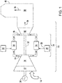
- FIG. 1 provides a functional block diagram of an exemplary gas turbine 10 that may incorporate various embodiments of the present disclosure.
- the gas turbine 10 generally includes an inlet section 12 that may include a series of filters, cooling coils, moisture separators, and/or other devices to purify and otherwise condition a working fluid (e.g., air) 14 entering the gas turbine 10.
- the working fluid 14 flows to a compressor section where a compressor 16 progressively imparts kinetic energy to the working fluid 14 to produce a compressed working fluid 18.
- the compressed working fluid 18 is mixed with a fuel 20 from a fuel source 22 such as a fuel skid to form a combustible mixture within one or more combustors 24 of a combustion section 26 of the gas turbine 10.
- the combustible mixture is burned to produce combustion gases 28 having a high temperature, pressure and velocity.
- the combustion gases 28 flow through a turbine 30 of a turbine section to produce work.
- the turbine 30 may be connected to a shaft 32 so that rotation of the turbine 30 drives the compressor 16 to produce the compressed working fluid 18.
- the shaft 32 may connect the turbine 30 to a generator 34 for producing electricity.
- Exhaust gases 36 from the turbine 30 flow through an exhaust section 38 that connects the turbine 30 to an exhaust stack 40 downstream from the turbine 30.
- the exhaust section 38 may include, for example, a heat recovery steam generator (not shown) for cleaning and extracting additional heat from the exhaust gases 36 prior to release to the environment.
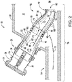
- FIG. 2 provides a cross sectional side view of a portion of the gas turbine 10 including an exemplary combustor 24 as may be incorporated in various embodiments of the present invention.
- the combustion section 26 includes an outer casing 50, such as a compressor discharge casing, disposed downstream from the compressor 16.
- the outer casing 50 at least partially surrounds the combustor 24.
- the outer casing 50 at least partially defines a high pressure plenum 52 that at least partially surrounds the combustor 24.
- the high pressure plenum 52 is in fluid communication with the compressor 16 so as to receive the compressed working fluid 18 from the compressor 16 during operation of the gas turbine 10.
- An end cover 54 may be connected to the outer casing 50.
- the end cover 54 is in fluid communication with the fuel source 22.
- a fuel nozzle 56 in fluid communication with the end cover 54 and/or the fuel source 22 extends downstream from the end cover 54.
- the fuel nozzle 56 extends generally axially through an annular cap assembly 58 disposed within the outer casing 50.
- An annular liner 60 such as a combustion liner or transition duct at least partially defines a combustion chamber 62 within the combustor 24 downstream from an outlet end 64 of the fuel nozzle 56.
- a flow sleeve 66 may circumferentially surround at least a portion of the liner 60.
- the flow sleeve 66 is radially separated from the liner 60 so as to define a flow passage 68 therebetween.
- the flow passage 68 is in fluid communication with the combustion chamber 62 via a head end portion 70 of the combustor 24.
- the head end portion 70 may be at least partially defined by the end cover 54 and/or the outer casing 50.
- a transition duct (or transition piece) 72 extends downstream from the combustion chamber 62.
- the transition piece 72 includes an upstream end 74 that is axially separated from a downstream end 76.
- the upstream end 74 surrounds a downstream portion 78 of the annular liner 60.
- the downstream end 76 of the transition piece 72 terminates proximate to an inlet 80 of the turbine 30.
- the annular liner 60 and/or the transition piece 72 at least partially define a hot gas path 82 for routing the combustion gases 28 from the combustion chamber 62 through the high pressure plenum 52 and into the turbine 30.
- An outer sleeve 84 such as an impingement or flow sleeve extends circumferentially around the transition piece 72.
- the outer sleeve 84 is radially separated from the transition piece 72 to define a cooling annulus 86 therebetween.
- the outer sleeve 84 may include a plurality of cooling holes 88 or passages that provide for fluid communication between the high pressure plenum 52 and the cooling annulus 86.
- the cooling annulus 86 is in fluid communication with the combustion chamber 62.
- One or more fuel injectors 90 may extend through the outer sleeve 84, the cooling annulus 86 and the transition piece 72 to provide for fuel injection into the hot gas path 82 downstream from the combustion chamber 62.
- the fuel injectors 90 may extend through the flow sleeve 66, the flow passage 68 and the liner 60 to provide for fuel injection into the hot gas path 82 downstream from the combustion chamber 62.
- other penetrations such as cross fire tubes, igniters, pressure probes and flame detectors may act as bluff bodies within the flow annulus 86, thus creating disturbances to the flow such as wakes.
- An aft frame assembly (or aft frame) 92 is disposed at or proximate to the downstream end 76 of the transition piece 72.
- the aft frame 92 is integral with the downstream end 76 of the transition piece 72.
- a portion of the outer sleeve 84 such as a forward edge 94 may be integral or connected to the aft frame 92 to at least partially define the cooling annulus 86.
- the aft frame 92 and the transition piece 72 may be manufactured as a singular component. In the alternative, the aft frame 92 may be connected to the transition piece 72 via welding, brazing or any other suitable process.
- the transition piece 72, the outer sleeve 84, the cooling annulus 86 and the aft frame 92 are provided as a transition piece assembly 96.
- the aft frame 92 generally provides structural support to reduce and/or prevent deformation of the downstream end 76 of the transition piece 72 during operation of the combustor.
- the aft frame 92 may provide a means for mounting the transition piece 72 within the outer casing 50.
- the aft frame 92 comprises a main body 100.
- the main body 100 includes an outer (or top) rail 102, an inner (or bottom) rail 104 and a first side rail 106 that is circumferentially separated from an opposing second side rail 108.
- the side rails are located on the sides of the aft frame, the outer rail is located on the top of the aft frame, and the inner rail is located on the bottom of the aft frame.
- Top rail 102 is located radially outward of bottom rail 104.
- the main body 100 further includes an upstream facing surface 110 (not visible in FIG.
- the aft frame 92 may also include a mounting feature 116 for the mounting transition piece 72 and/or the transition piece assembly 96 ( FIG. 2 ) within the gas turbine 10.
- the side rails of the aft frame have unique cooling needs due to the transition from a "can" combustor to an "annular" hot gas path where the inner and outer rails match up to the hot gas path.
- the side rails of the aft frame have no corresponding part in the hot gas path and therefore are exposed to hot gases more directly than the inner and outer rails.
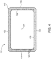
- FIG. 4 illustrates a simplified, schematic view of the upstream facing surface 110 of aft frame 92, with the mounting feature 116 omitted for clarity.
- the upstream facing surface 110 includes a plurality of feed hole inlets 120 located thereon.
- Each of the feed hole inlets 120 is coupled to a cooling channel 122 that passes through the main body 100 and in a direction towards the downstream surface 112 (not shown in FIG. 4 ).
- one feed hole inlet 120 functions as the beginning of a respective cooling channel 122, so a plurality of feed hole inlets 120 correspond to an equal number of cooling channels 122.
- the source of air input to the feed hole inlets 120 may be post-impingement cooling air drawn from between the transition piece 72 and the outer sleeve 84, which is otherwise referred to as cooling annulus 86.
- the specific locations or configuration of the feed hole inlets and cooling channels may be tailored to the specific application, so that thermal gradients in the aft frame are minimized or reduced.
- the radially inner surface 109 of the aft frame 92 is typically hotter than the radially outer surfaces 102, 104, 106, 108, so the feed hole inlets 120 and respective cooling channels 122 may be located nearer or close to the radially inner surface 109.
- the phrases "radially inner” and "radially outer” are used with respect to central origin point 111, which is a central point with respect to aft frame 92.
- FIG. 5 illustrates a simplified, side view of the aft frame, according to an aspect of the present disclosure.
- a seal slot 103 extends circumferentially around the aft frame 92, and a seal 105 (shown in phantom) is placed in the seal slot 103.
- the seal slot 103 forms a groove or slot in the main body 100.
- the seal 105 may be paired with a wear shim (not shown), that also fits inside seal slot 103.
- the seal slot includes an upstream facing surface 107 and a downstream facing surface 113, and a radially outer facing surface (i.e., the bottom of the groove/slot).
- a gap exists between the upstream facing surface 107 of the seal slot 103 and the opposing surface of the seal 105. This gap will be used to assist in cooling of the aft frame and the space between neighboring aft frames.
- FIG. 6 illustrates a side, cross-sectional view of the aft frame 92, according to an aspect of the present disclosure.
- the feed hole inlets 120 are located on the upstream facing surface 110, and each of the feed hole inlets is connected to a cooling channel 122.
- the cooling channels 122 pass through the main body 100 of the aft frame and extend towards the downstream surface 112.
- the cooling channels 122 may pass straight or axially through the main body, or may be angled with respect to an axial line passing through central origin point 111.
- the term "axial" is with reference to the aft frame and is generally in the direction of the flow of combustion gasses, or in other words, into the page of FIG. 4 or right to left in FIGs. 5 and 6 .
- the term "radial" is any direction at right angles to the axial direction.
- the cooling channels 122 are connected to and terminate (or exhaust into) plenums 124.
- Each cooling channel 122 is connected to one plenum 124, and one plenum is connected to multiple cooling channels 122.
- Each plenum 124 has multiple "inputs" from a plurality (i.e., two or more) of cooling channels 122. This configuration is advantageous, because it minimizes or reduces the adverse effects of clogging of the cooling channels. If one cooling channel becomes clogged (or otherwise obstructed) the other cooling channels feeding the same plenum will continue to provide cooling airflow to the plenum.
- Each plenum 124 is connected to a plurality of microchannels 126.
- the microchannels 126 are formed in or near the downstream facing surface 112, and extend outward toward (but not to) the radially outer surfaces.
- the microchannels 126 may have depths in the range from approximately 0.2 millimeters (mm) to approximately 3 mm, or 0.5 mm to 1 mm, or any subranges therebetween. Further, the microchannels 126 may have widths in the range from approximately 0.2 mm to approximately 3 mm, or 0.5 mm to 1 mm, or any subranges therebetween.
- the length of each microchannel 126 will vary based on the distance from the plenum to the end point of the microchannel.
- the microchannels 126 may be covered by a cover member 128, such as pre-sintered preform, sheet metal or additively manufactured (3-D printed) member that is brazed or diffusion-bonded to the main body 100.
- the base alloy of the pre-sintered preform can comprise any composition such as one similar to the main body 100 to promote common physical properties between the pre-sintered preform and the main body 100.
- the base alloy and the main body share a common composition (i.e., they are the same type of material).
- the base alloy can comprise a superalloy, a nickel-based superalloy or a cobalt-based superalloy.
- the properties for the base alloy include chemical and metallurgical compatibility with the main body 100.
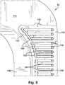
- FIG. 7 illustrates a partial, end view of the downstream side of the aft frame 92
- FIG. 8 illustrates an enlarged view of the upper right portion of FIG. 7 , according to an aspect of the present disclosure.
- the cover member 128 is omitted for clarity.
- the cooling channels 122 are shown terminating in plenums 124.
- the microchannels 126 extend from the plenums 124 toward the outer radial surfaces (e.g., 102, 106) of the aft frame, but terminate before the outer radial surfaces into exit channels 130 where the cooling air is then discharged into the seal slot 103 out of the upstream facing surface 107.
- the exit channels 130 begin at the outer radial end of the microchannels 126, and extend axially back (in the upstream direction) to the seal slot 103.
- Each plenum 124 may have two or more cooling channels 122 as inputs.
- Each plenum may also have two or more microchannels as outputs thereof. With this configuration, obstruction of any one input (or output) will not cut off cooling flow to the plenum and any un-obstructed input or output cooling channels/slots. This prevents any one area of the aft frame from overheating due to obstructed cooling holes, cooling channels or microchannel cooling slots.
- the microchannel cooling slots 126 may be configured to be straight, curved or serpentine, to obtain the desired degree of cooling of the aft frame.
- a land 132 is formed around the perimeter of the plenums 124 and microchannels 126.
- the land 132 is an area that is recessed into upstream facing surface 112, but land 132 is not formed as deep as plenums 124 and microchannels 126.
- the land 132 provides a good bonding surface for the cover member 128, and the surface area provided by land 132 yields excellent bonding results between the surface of land 132 and the cover member 128.
- the depth of land 132 is selected to be about the same depth (or thickness) as the cover member 128.
- FIG. 9 illustrates a partial, side view of the aft frame 92, according to an aspect of the present disclosure.
- the exit channels 130 are shown exiting on the upstream facing surface 107 of the seal slot 103.
- the exit channels 130 begin on the downstream facing surface 112 and in a substantially straight path extend to upstream facing surface 107 of the seal slot 103.
- the seal is omitted for clarity.
- the slot 103 includes a plurality of spacers 134 and a plurality of recesses 136.
- the seal 105 will abut the top of the spacers 134, and this creates a cavity between the seal 105 and the bottom of each recess 136.
- the recesses 136 permit the cooling air to exhaust from the sides of the aft frame 92, and cool the regions between adjacent aft frames and transition pieces.
- the microchannels 126 and exit channels 130 may extend along one or both sides of the aft frame, and may also extend along the top and/or bottom of the aft frame. The specific location of the microchannels and exit channels will be selected based on cooling needs of the aft frame and thermal gradient reduction objectives.
- FIG. 10 illustrates a side view of the aft frame 92 where the aft frame includes exhaust slots 138 on the side rails thereof, according to an aspect of the present disclosure.
- a series of exhaust slots 138 may be formed into the side rails 106 (as shown) and 108, and/or the outer/top rail 102 and the inner/bottom rail 104.
- the exit channels 130 terminate in these exhaust slots 138, with the resulting cooling air being exhausted out of the exhaust slots 138.
- This configuration will directly cool the spaces between neighboring aft frames.
- the seal slot 103 is not modified, but the side rails 106 and 108 are machined to include the exhaust slots 138.
- the cooling flow is similar to previous embodiments, in that flow begins at feed hole inlets 120, travels along cooling channels 122 to plenums 124 and then microchannels 126 and then back through exit channels 130. The only difference is that exit channels 130 exhaust into exhaust slots 138, without having the cooling airflow continue on to seal slot 103.
- Approximating language may be applied to modify any quantitative representation that could permissibly vary without resulting in a change in the basic function to which it is related. Accordingly, a value modified by a term or terms, such as “about,” “approximately” and “substantially,” are not to be limited to the precise value specified. In at least some instances, the approximating language may correspond to the precision of an instrument for measuring the value.
- range limitations may be combined and/or interchanged, such ranges are identified and include all the sub-ranges contained therein unless context or language indicates otherwise.
- the terms “about” and “approximately” as applied to a particular value of a range applies to both values, and unless otherwise dependent on the precision of the instrument measuring the value, may indicate +/- 10% of the stated value(s).
Landscapes
- Engineering & Computer Science (AREA)
- Mechanical Engineering (AREA)
- General Engineering & Computer Science (AREA)
- Chemical & Material Sciences (AREA)
- Combustion & Propulsion (AREA)
- Physics & Mathematics (AREA)
- Fluid Mechanics (AREA)
- Turbine Rotor Nozzle Sealing (AREA)
Abstract
Description
- The apparatus described herein relates generally to aft frame assemblies, and more specifically, to an aft frame assembly for a transition piece of a gas turbine where the aft frame assembly includes plenum chambers in fluid communication with microchannel cooling slots.
- Turbine systems are widely utilized in fields such as power generation. For example, a conventional gas turbine system includes a compressor, a combustor, and a turbine. In a conventional gas turbine system, compressed air is provided from the compressor to the combustor. The air entering the combustor is mixed with fuel and combusted. Hot gases of combustion flow from the combustor to the turbine to drive the gas turbine system and generate power.
- In a typical arrangement, an annular array of combustors is connected to the first stage of the turbine by a plurality of transition pieces. The transition pieces are each shaped at one end to conform to respective combustor liners, and at an opposite end to conform to the inlet of the turbine. Thus, at the opposite (or downstream) end, a transition piece has an aft frame by which the transition piece is secured to the turbine. An impingement sleeve may surround the transition duct, and may be used to direct working fluid discharged from the compressor into contact with the transition piece. This working fluid eventually mixes with the fuel in the combustor.
- Currently, some of the working fluid that enters the flow path between the transition piece and the surrounding impingement sleeve is removed through holes in the aft frame. This working fluid, which is used to cool the aft frame, dumps into the hot gas from the combustor just before the hot gas enters the turbine. The problem with this current cooling method is that this working fluid does not always reach the areas of the aft frame that need to be cooled.
- In an aspect of the present invention, an aft frame assembly for a gas turbine transition piece is provided. The aft frame assembly includes a main body comprising an upstream facing surface, a downstream facing surface and a seal slot. A plurality of feed hole inlets are located on the upstream facing surface, and each of the feed hole inlets is coupled to one of a plurality of cooling channels that pass through the main body towards the downstream facing surface. A plurality of plenums are located in or near the downstream facing surface, and each of the plurality of cooling channels are connected to and terminate in one or at least one of the plenums. The cooling channels are configured as inputs to the plenums. A plurality of microchannels are formed in or near the downstream facing surface, and each of the plurality of microchannels is connected to one of the plenums. The microchannels are configured as outputs of the plenums. Two or more of the cooling channels and two or more of the microchannels are connected to one of the plenums. A plurality of exit channels are connected to the microchannels, and the exit channels are configured to exhaust flow out of an upstream facing surface of the seal slot or exhaust flow out of one or more exhaust slots formed in a side rail of the aft frame assembly.
- In another aspect of the present invention, a transition piece assembly has an aft frame assembly. The aft frame assembly includes a main body with an upstream facing surface, a downstream facing surface and a seal slot. A plurality of feed hole inlets are located on the upstream facing surface, and each of the feed hole inlets is coupled to one of a plurality of cooling channels passing through the main body towards the downstream facing surface. A plurality of plenums are located in or near the downstream facing surface, and each of the plurality of cooling channels is connected to and terminates in at least one of the plenums. The cooling channels are configured as inputs to the plenums. A plurality of microchannels are formed in or near the downstream facing surface, and each of the plurality of microchannels is connected to one of the plenums. The microchannels are configured as outputs of the plenums. Two or more of the cooling channels and two or more of the microchannels are connected to one of the plenums. A plurality of exit channels are connected to the microchannels, and the exit channels exhaust flow out of an upstream facing surface of the seal slot.
- In yet another aspect of the present invention, a gas turbine includes a compressor and a combustion section disposed downstream from the compressor. The combustion section is in fluid communication with the compressor. A turbine is disposed downstream from the combustion section, and the turbine is in fluid communication with the combustion section. The combustion section includes an aft frame assembly having a main body with an upstream facing surface, a downstream facing surface and a seal slot. The seal slot extends substantially circumferentially around the aft frame assembly. A plurality of feed hole inlets are located on the upstream facing surface. Each feed hole inlet is coupled to one of a plurality of cooling channels that pass through the main body towards the downstream facing surface. A plurality of plenums are located in or near the downstream facing surface. Each of the plurality of cooling channels is connected to and terminates in at least one of the plenums. The cooling channels are configured as inputs to the plenums. A plurality of microchannels are formed in or near the downstream facing surface. Each of the plurality of microchannels is connected to one of the plenums. The microchannels are configured as outputs of the plenums. Two or more of the cooling channels and two or more of the microchannels are connected to one of the plenums. A plurality of exit channels are connected to the microchannels, and the exit channels are configured to exhaust flow out of an upstream facing surface of the seal slot. The plurality of microchannels are covered by a cover member formed of a pre-sintered preform, or sheet metal, or an additively manufactured member.
-
-
FIG. 1 is a functional block diagram of an exemplary gas turbine. -
FIG. 2 illustrates a cross sectional side view of a portion of a gas turbine, including a combustor that may encompass various aspects of the present disclosure. -
FIG. 3 illustrates a perspective view of an aft frame of the combustor as shown inFIG. 2 , according to an aspect of the present disclosure. -
FIG. 4 illustrates a schematic view of the upstream facing surface of the aft frame assembly, according to an aspect of the present disclosure. -
FIG. 5 illustrates a side view of the aft frame, according to an aspect of the present disclosure. -
FIG. 6 illustrates a side, cross-sectional view of the aft frame, according to an aspect of the present disclosure. -
FIG. 7 illustrates a partial, end view of the downstream side of the aft frame, according to an aspect of the present disclosure. -
FIG. 8 illustrates an enlarged view of the upper right portion ofFIG. 7 , according to an aspect of the present disclosure. -
FIG. 9 illustrates a partial, side view of the aft frame showing the exit channels exhausting from an upstream facing surface of the seal slot, according to an aspect of the present disclosure. -
FIG. 10 illustrates a side view of the aft frame where the aft frame includes exhaust slots on the side rails thereof, according to an aspect of the present disclosure. - One or more specific aspects/embodiments of the present invention will be described below. In an effort to provide a concise description of these aspects/embodiments, all features of an actual implementation may not be described in the specification. It should be appreciated that in the development of any such actual implementation, as in any engineering or design project, numerous implementation-specific decisions must be made to achieve the developers' specific goals, such as compliance with machine-related, system-related and business-related constraints, which may vary from one implementation to another. Moreover, it should be appreciated that such a development effort might be complex and time consuming, but would nevertheless be a routine undertaking of design, fabrication, and manufacture for those of ordinary skill having the benefit of this disclosure.
- When introducing elements of various embodiments of the present invention, the articles "a," "an," and "the" are intended to mean that there are one or more of the elements. The terms "comprising," "including," and "having" are intended to be inclusive and mean that there may be additional elements other than the listed elements. Any examples of operating parameters and/or environmental conditions are not exclusive of other parameters/conditions of the disclosed embodiments. Additionally, it should be understood that references to "one embodiment", "one aspect" or "an embodiment" or "an aspect" of the present invention are not intended to be interpreted as excluding the existence of additional embodiments or aspects that also incorporate the recited features.
- As used herein, the terms "upstream" and "downstream" refer to the relative direction with respect to fluid flow in a fluid pathway. For example, "upstream" refers to the direction from which the fluid flows, and "downstream" refers to the direction to which the fluid flows. The term "radially" refers to the relative direction that is substantially perpendicular to an axial centerline of a particular component, and the term "axially" refers to the relative direction that is substantially parallel to an axial centerline of a particular component, and perpendicular to the radial direction.
- Referring now to the drawings, wherein identical numerals indicate the same elements throughout the figures,
FIG. 1 provides a functional block diagram of anexemplary gas turbine 10 that may incorporate various embodiments of the present disclosure. As shown, thegas turbine 10 generally includes aninlet section 12 that may include a series of filters, cooling coils, moisture separators, and/or other devices to purify and otherwise condition a working fluid (e.g., air) 14 entering thegas turbine 10. The workingfluid 14 flows to a compressor section where acompressor 16 progressively imparts kinetic energy to the workingfluid 14 to produce a compressed workingfluid 18. - The compressed working
fluid 18 is mixed with afuel 20 from afuel source 22 such as a fuel skid to form a combustible mixture within one ormore combustors 24 of acombustion section 26 of thegas turbine 10. The combustible mixture is burned to producecombustion gases 28 having a high temperature, pressure and velocity. Thecombustion gases 28 flow through aturbine 30 of a turbine section to produce work. For example, theturbine 30 may be connected to ashaft 32 so that rotation of theturbine 30 drives thecompressor 16 to produce the compressed workingfluid 18. - Alternately or in addition, the
shaft 32 may connect theturbine 30 to agenerator 34 for producing electricity.Exhaust gases 36 from theturbine 30 flow through anexhaust section 38 that connects theturbine 30 to anexhaust stack 40 downstream from theturbine 30. Theexhaust section 38 may include, for example, a heat recovery steam generator (not shown) for cleaning and extracting additional heat from theexhaust gases 36 prior to release to the environment. -
FIG. 2 provides a cross sectional side view of a portion of thegas turbine 10 including anexemplary combustor 24 as may be incorporated in various embodiments of the present invention. As shown inFIG. 2 , thecombustion section 26 includes anouter casing 50, such as a compressor discharge casing, disposed downstream from thecompressor 16. Theouter casing 50 at least partially surrounds thecombustor 24. Theouter casing 50 at least partially defines ahigh pressure plenum 52 that at least partially surrounds thecombustor 24. Thehigh pressure plenum 52 is in fluid communication with thecompressor 16 so as to receive the compressed workingfluid 18 from thecompressor 16 during operation of thegas turbine 10. - An end cover 54 may be connected to the
outer casing 50. In particular combustor designs, the end cover 54 is in fluid communication with thefuel source 22. Afuel nozzle 56 in fluid communication with the end cover 54 and/or thefuel source 22 extends downstream from the end cover 54. Thefuel nozzle 56 extends generally axially through anannular cap assembly 58 disposed within theouter casing 50. Anannular liner 60 such as a combustion liner or transition duct at least partially defines acombustion chamber 62 within thecombustor 24 downstream from an outlet end 64 of thefuel nozzle 56. Aflow sleeve 66 may circumferentially surround at least a portion of theliner 60. Theflow sleeve 66 is radially separated from theliner 60 so as to define a flow passage 68 therebetween. The flow passage 68 is in fluid communication with thecombustion chamber 62 via ahead end portion 70 of thecombustor 24. Thehead end portion 70 may be at least partially defined by the end cover 54 and/or theouter casing 50. - A transition duct (or transition piece) 72 extends downstream from the
combustion chamber 62. Thetransition piece 72 includes anupstream end 74 that is axially separated from adownstream end 76. In particular configurations, theupstream end 74 surrounds adownstream portion 78 of theannular liner 60. Thedownstream end 76 of thetransition piece 72 terminates proximate to aninlet 80 of theturbine 30. Theannular liner 60 and/or thetransition piece 72 at least partially define ahot gas path 82 for routing thecombustion gases 28 from thecombustion chamber 62 through thehigh pressure plenum 52 and into theturbine 30. - An
outer sleeve 84 such as an impingement or flow sleeve extends circumferentially around thetransition piece 72. Theouter sleeve 84 is radially separated from thetransition piece 72 to define a coolingannulus 86 therebetween. Theouter sleeve 84 may include a plurality of cooling holes 88 or passages that provide for fluid communication between thehigh pressure plenum 52 and the coolingannulus 86. In one embodiment, the coolingannulus 86 is in fluid communication with thecombustion chamber 62. - One or
more fuel injectors 90, also commonly known as late lean fuel injectors, may extend through theouter sleeve 84, the coolingannulus 86 and thetransition piece 72 to provide for fuel injection into thehot gas path 82 downstream from thecombustion chamber 62. In addition or in the alternative, thefuel injectors 90 may extend through theflow sleeve 66, the flow passage 68 and theliner 60 to provide for fuel injection into thehot gas path 82 downstream from thecombustion chamber 62. In addition or in the alternative, other penetrations such as cross fire tubes, igniters, pressure probes and flame detectors may act as bluff bodies within theflow annulus 86, thus creating disturbances to the flow such as wakes. - An aft frame assembly (or aft frame) 92 is disposed at or proximate to the
downstream end 76 of thetransition piece 72. Theaft frame 92 is integral with thedownstream end 76 of thetransition piece 72. A portion of theouter sleeve 84 such as a forward edge 94 may be integral or connected to theaft frame 92 to at least partially define the coolingannulus 86. Theaft frame 92 and thetransition piece 72 may be manufactured as a singular component. In the alternative, theaft frame 92 may be connected to thetransition piece 72 via welding, brazing or any other suitable process. In one embodiment, thetransition piece 72, theouter sleeve 84, the coolingannulus 86 and theaft frame 92 are provided as atransition piece assembly 96. Theaft frame 92 generally provides structural support to reduce and/or prevent deformation of thedownstream end 76 of thetransition piece 72 during operation of the combustor. In addition or in the alternative, theaft frame 92 may provide a means for mounting thetransition piece 72 within theouter casing 50. - As shown in
FIG. 3 , theaft frame 92 comprises amain body 100. Themain body 100 includes an outer (or top)rail 102, an inner (or bottom)rail 104 and afirst side rail 106 that is circumferentially separated from an opposingsecond side rail 108. The side rails are located on the sides of the aft frame, the outer rail is located on the top of the aft frame, and the inner rail is located on the bottom of the aft frame.Top rail 102 is located radially outward ofbottom rail 104. Themain body 100 further includes an upstream facing surface 110 (not visible inFIG. 3 ) separated from (and opposed to) a downstream facingsurface 112, and an outer surface orsurface 114 that extends around an outer perimeter of themain body 100 at least partially between the upstream facingsurface 110 and the downstream facingsurface 112. Theaft frame 92 may also include a mountingfeature 116 for the mountingtransition piece 72 and/or the transition piece assembly 96 (FIG. 2 ) within thegas turbine 10. - The side rails of the aft frame have unique cooling needs due to the transition from a "can" combustor to an "annular" hot gas path where the inner and outer rails match up to the hot gas path. However, the side rails of the aft frame have no corresponding part in the hot gas path and therefore are exposed to hot gases more directly than the inner and outer rails.
-
FIG. 4 illustrates a simplified, schematic view of the upstream facingsurface 110 ofaft frame 92, with the mountingfeature 116 omitted for clarity. The upstream facingsurface 110 includes a plurality offeed hole inlets 120 located thereon. Each of thefeed hole inlets 120 is coupled to acooling channel 122 that passes through themain body 100 and in a direction towards the downstream surface 112 (not shown inFIG. 4 ). For example, onefeed hole inlet 120 functions as the beginning of arespective cooling channel 122, so a plurality offeed hole inlets 120 correspond to an equal number ofcooling channels 122. - The source of air input to the
feed hole inlets 120 may be post-impingement cooling air drawn from between thetransition piece 72 and theouter sleeve 84, which is otherwise referred to as coolingannulus 86. The specific locations or configuration of the feed hole inlets and cooling channels may be tailored to the specific application, so that thermal gradients in the aft frame are minimized or reduced. The radiallyinner surface 109 of theaft frame 92 is typically hotter than the radiallyouter surfaces feed hole inlets 120 andrespective cooling channels 122 may be located nearer or close to the radiallyinner surface 109. The phrases "radially inner" and "radially outer" are used with respect tocentral origin point 111, which is a central point with respect toaft frame 92. -
FIG. 5 illustrates a simplified, side view of the aft frame, according to an aspect of the present disclosure. Aseal slot 103 extends circumferentially around theaft frame 92, and a seal 105 (shown in phantom) is placed in theseal slot 103. Theseal slot 103 forms a groove or slot in themain body 100. Theseal 105 may be paired with a wear shim (not shown), that also fits insideseal slot 103. The seal slot includes an upstream facingsurface 107 and a downstream facingsurface 113, and a radially outer facing surface (i.e., the bottom of the groove/slot). A gap exists between the upstream facingsurface 107 of theseal slot 103 and the opposing surface of theseal 105. This gap will be used to assist in cooling of the aft frame and the space between neighboring aft frames. -
FIG. 6 illustrates a side, cross-sectional view of theaft frame 92, according to an aspect of the present disclosure. Thefeed hole inlets 120 are located on the upstream facingsurface 110, and each of the feed hole inlets is connected to acooling channel 122. The coolingchannels 122 pass through themain body 100 of the aft frame and extend towards thedownstream surface 112. The coolingchannels 122 may pass straight or axially through the main body, or may be angled with respect to an axial line passing throughcentral origin point 111. The term "axial" is with reference to the aft frame and is generally in the direction of the flow of combustion gasses, or in other words, into the page ofFIG. 4 or right to left inFIGs. 5 and 6 . The term "radial" is any direction at right angles to the axial direction. The coolingchannels 122 are connected to and terminate (or exhaust into)plenums 124. Each coolingchannel 122 is connected to oneplenum 124, and one plenum is connected tomultiple cooling channels 122. Eachplenum 124 has multiple "inputs" from a plurality (i.e., two or more) of coolingchannels 122. This configuration is advantageous, because it minimizes or reduces the adverse effects of clogging of the cooling channels. If one cooling channel becomes clogged (or otherwise obstructed) the other cooling channels feeding the same plenum will continue to provide cooling airflow to the plenum. - Each
plenum 124 is connected to a plurality ofmicrochannels 126. Themicrochannels 126 are formed in or near the downstream facingsurface 112, and extend outward toward (but not to) the radially outer surfaces. Themicrochannels 126 may have depths in the range from approximately 0.2 millimeters (mm) to approximately 3 mm, or 0.5 mm to 1 mm, or any subranges therebetween. Further, themicrochannels 126 may have widths in the range from approximately 0.2 mm to approximately 3 mm, or 0.5 mm to 1 mm, or any subranges therebetween. The length of each microchannel 126 will vary based on the distance from the plenum to the end point of the microchannel. Themicrochannels 126 may be covered by acover member 128, such as pre-sintered preform, sheet metal or additively manufactured (3-D printed) member that is brazed or diffusion-bonded to themain body 100. - If the
cover member 128 is a pre-sintered preform, the base alloy of the pre-sintered preform can comprise any composition such as one similar to themain body 100 to promote common physical properties between the pre-sintered preform and themain body 100. For example, in some embodiments, the base alloy and the main body share a common composition (i.e., they are the same type of material). In some embodiments, the base alloy can comprise a superalloy, a nickel-based superalloy or a cobalt-based superalloy. In some embodiments, the properties for the base alloy include chemical and metallurgical compatibility with themain body 100. -
FIG. 7 illustrates a partial, end view of the downstream side of theaft frame 92, andFIG. 8 illustrates an enlarged view of the upper right portion ofFIG. 7 , according to an aspect of the present disclosure. Thecover member 128 is omitted for clarity. The coolingchannels 122 are shown terminating inplenums 124. Themicrochannels 126 extend from theplenums 124 toward the outer radial surfaces (e.g., 102, 106) of the aft frame, but terminate before the outer radial surfaces intoexit channels 130 where the cooling air is then discharged into theseal slot 103 out of the upstream facingsurface 107. Theexit channels 130 begin at the outer radial end of themicrochannels 126, and extend axially back (in the upstream direction) to theseal slot 103. Eachplenum 124 may have two ormore cooling channels 122 as inputs. Each plenum may also have two or more microchannels as outputs thereof. With this configuration, obstruction of any one input (or output) will not cut off cooling flow to the plenum and any un-obstructed input or output cooling channels/slots. This prevents any one area of the aft frame from overheating due to obstructed cooling holes, cooling channels or microchannel cooling slots. Furthermore, themicrochannel cooling slots 126 may be configured to be straight, curved or serpentine, to obtain the desired degree of cooling of the aft frame. - A
land 132 is formed around the perimeter of theplenums 124 andmicrochannels 126. Theland 132 is an area that is recessed into upstream facingsurface 112, butland 132 is not formed as deep asplenums 124 andmicrochannels 126. Theland 132 provides a good bonding surface for thecover member 128, and the surface area provided byland 132 yields excellent bonding results between the surface ofland 132 and thecover member 128. As one example only, the depth ofland 132 is selected to be about the same depth (or thickness) as thecover member 128. -
FIG. 9 illustrates a partial, side view of theaft frame 92, according to an aspect of the present disclosure. Theexit channels 130 are shown exiting on the upstream facingsurface 107 of theseal slot 103. For example, theexit channels 130 begin on the downstream facingsurface 112 and in a substantially straight path extend to upstream facingsurface 107 of theseal slot 103. The seal is omitted for clarity. Theslot 103 includes a plurality ofspacers 134 and a plurality ofrecesses 136. Theseal 105 will abut the top of thespacers 134, and this creates a cavity between theseal 105 and the bottom of eachrecess 136. Therecesses 136 permit the cooling air to exhaust from the sides of theaft frame 92, and cool the regions between adjacent aft frames and transition pieces. - The
microchannels 126 and exitchannels 130 may extend along one or both sides of the aft frame, and may also extend along the top and/or bottom of the aft frame. The specific location of the microchannels and exit channels will be selected based on cooling needs of the aft frame and thermal gradient reduction objectives. -
FIG. 10 illustrates a side view of theaft frame 92 where the aft frame includesexhaust slots 138 on the side rails thereof, according to an aspect of the present disclosure. As an alternative to the recesses and spacers shown inFIG. 9 , a series ofexhaust slots 138 may be formed into the side rails 106 (as shown) and 108, and/or the outer/top rail 102 and the inner/bottom rail 104. Theexit channels 130 terminate in theseexhaust slots 138, with the resulting cooling air being exhausted out of theexhaust slots 138. This configuration will directly cool the spaces between neighboring aft frames. In this embodiment, theseal slot 103 is not modified, but the side rails 106 and 108 are machined to include theexhaust slots 138. The cooling flow is similar to previous embodiments, in that flow begins atfeed hole inlets 120, travels along coolingchannels 122 toplenums 124 and then microchannels 126 and then back throughexit channels 130. The only difference is thatexit channels 130 exhaust intoexhaust slots 138, without having the cooling airflow continue on to sealslot 103. - Approximating language, as used herein throughout the specification and claims, may be applied to modify any quantitative representation that could permissibly vary without resulting in a change in the basic function to which it is related. Accordingly, a value modified by a term or terms, such as "about," "approximately" and "substantially," are not to be limited to the precise value specified. In at least some instances, the approximating language may correspond to the precision of an instrument for measuring the value. Here and throughout the specification and claims, range limitations may be combined and/or interchanged, such ranges are identified and include all the sub-ranges contained therein unless context or language indicates otherwise. The terms "about" and "approximately" as applied to a particular value of a range applies to both values, and unless otherwise dependent on the precision of the instrument measuring the value, may indicate +/- 10% of the stated value(s).
- This written description uses examples to disclose the invention and also to enable any person skilled in the art to practice the invention, including making and using any devices or systems and performing any incorporated methods. The patentable scope of the invention is defined by the claims, and may include other examples that occur to those skilled in the art. Such other examples are intended to be within the scope of the claims if they have structural elements that do not differ from the literal language of the claims, or if they include equivalent structural elements with insubstantial differences from the literal languages of the claims.
- Various aspects and embodiments of the present invention are defined by the following numbered clauses:
- 1. An aft frame assembly for a gas turbine transition piece, the aft frame assembly comprising:
- a main body comprising an upstream facing surface, a downstream facing surface and a seal slot;
- a plurality of feed hole inlets located on the upstream facing surface, each of the feed hole inlets coupled to one of a plurality of cooling channels passing through the main body towards the downstream facing surface;
- a plurality of plenums located in or near the downstream facing surface, each of the plurality of cooling channels connected to and terminating in at least one of the plenums, the cooling channels are configured as inputs to the plenums;
- a plurality of microchannels formed in or near the downstream facing surface, each of the plurality of microchannels connected to one of the plenums, two or more of the cooling channels and two or more of the microchannels are connected to one of the plenums, and the microchannels are configured as outputs of the plenums; and
- a plurality of exit channels connected to the microchannels, the exit channels are configured to exhaust flow out of an upstream facing surface of the seal slot or exhaust flow out of one or more exhaust slots formed in a side rail of the aft frame assembly.
- 2. The aft frame assembly of
clause 1, wherein at least a portion of the plurality of microchannels are covered by a cover member comprising:
a pre-sintered preform, or sheet metal, or an additively manufactured member. - 3. The aft frame assembly of any preceding clause, the downstream facing surface having a land disposed at an outer radial end of the microchannels, the land configured for bonding with the cover member.
- 4. The aft frame assembly of any preceding clause, the downstream facing surface having a land disposed around a perimeter of the plenums and the microchannels, the land configured for bonding with the cover member.
- 5. The aft frame assembly of any preceding clause, the upstream facing surface of the seal slot comprising a series of spacers and recesses, the exit channels exhausting flow into the recesses.
- 6. The aft frame assembly of any preceding clause, wherein the microchannels are located on sides of the aft frame assembly.
- 7. The aft frame assembly of any preceding clause, wherein the exit channels exhaust flow out of an upstream facing surface of a seal slot and subsequently out of a side rail of the aft frame assembly.
- 8. A transition piece assembly having an aft frame assembly, the aft frame assembly comprising:
- a main body comprising an upstream facing surface, a downstream facing surface and a seal slot;
- a plurality of feed hole inlets located on the upstream facing surface, each of the feed hole inlets coupled to one of a plurality of cooling channels passing through the main body towards the downstream facing surface;
- a plurality of plenums located in or near the downstream facing surface, each of the plurality of cooling channels connected to and terminating in at least one of the plenums, the cooling channels are configured as inputs to the plenums;
- a plurality of microchannels formed in or near the downstream facing surface, each of the plurality of microchannels connected to one of the plenums, two or more of the cooling channels and two or more of the microchannels are connected to one of the plenums, and the microchannels are configured as outputs of the plenums; and
- a plurality of exit channels connected to the microchannels, the exit channels are configured to exhaust flow out of an upstream facing surface of the seal slot or exhaust flow out of one or more exhaust slots formed in a side rail of the aft frame assembly.
- 9. The aft frame assembly of any preceding clause, wherein at least a portion of the plurality of microchannels are covered by a cover member comprising:
a pre-sintered preform, or sheet metal, or an additively manufactured member. - 10. The transition piece assembly of any preceding clause, the downstream facing surface having a land disposed at an outer radial end of the microchannels, the land configured for bonding with the cover member.
- 11. The transition piece assembly of any preceding clause, the downstream facing surface having a land disposed around a perimeter of the plenums and the microchannels, the land configured for bonding with the cover member.
- 12. The transition piece assembly of any preceding clause, the upstream facing surface of the seal slot comprising a series of spacers and recesses, the exit channels exhausting flow into the recesses.
- 13. The transition piece assembly of any preceding clause, wherein the microchannels are located on sides of the aft frame assembly.
- 14. The transition piece assembly of any preceding clause, wherein the exit channels exhaust flow out of an upstream facing surface of a seal slot and subsequently out of a side rail of the aft frame assembly.
- 15. A gas turbine comprising:
- a compressor;
- a combustion section disposed downstream from the compressor, the combustion section being in fluid communication with the compressor;
- a turbine disposed downstream from the combustion section;
- the combustion section comprising an aft frame assembly having a main body comprising an upstream facing surface, a downstream facing surface and a seal slot;
- a plurality of feed hole inlets located on the upstream facing surface, each of the feed hole inlets coupled to one of a plurality of cooling channels passing through the main body towards the downstream facing surface;
- a plurality of plenums located in or near the downstream facing surface, each of the plurality of cooling channels connected to and terminating in at least one of the plenums, the cooling channels are configured as inputs to the plenums;
- a plurality of microchannels formed in or near the downstream facing surface, each of the plurality of microchannels connected to one of the plenums, two or more of the cooling channels and two or more of the microchannels are connected to one of the plenums, and the microchannels are configured as outputs of the plenums;
- a plurality of exit channels connected to the microchannels, the exit channels are configured to exhaust flow out of an upstream facing surface of the seal slot or exhaust flow out of one or more exhaust slots formed in a side rail of the aft frame assembly; and
- wherein at least a portion of the plurality of microchannels are covered by a cover member comprising a pre-sintered preform, or sheet metal, or an additively manufactured member.
- 16. The gas turbine of any preceding clause, the downstream facing surface having a land disposed at an outer radial end of the microchannels, the land configured for bonding with the cover member.
- 17. The gas turbine of any preceding clause, the downstream facing surface having a land disposed around a perimeter of the plenums and the microchannels, the land configured for bonding with the cover member.
- 18. The gas turbine of any preceding clause, the upstream facing surface of the seal slot comprising a series of spacers and recesses, the exit channels exhausting flow into the recesses.
- 19. The gas turbine of any preceding clause, wherein the microchannels are located on sides of the aft frame assembly.
- 20. The gas turbine of any preceding clause, wherein the exit channels exhaust flow out of an upstream facing surface of a seal slot and subsequently out of a side rail of the aft frame assembly.
Claims (15)
- An aft frame assembly (92) for a gas turbine transition piece (72), the aft frame assembly comprising:a main body (100) comprising an upstream facing surface (110), a downstream facing surface (112) and a seal slot (103);a plurality of feed hole inlets (120) located on the upstream facing surface, each of the feed hole inlets coupled to one of a plurality of cooling channels (122) passing through the main body towards the downstream facing surface;a plurality of plenums (124) located in or near the downstream facing surface, each of the plurality of cooling channels connected to and terminating in at least one of the plenums, the cooling channels are configured as inputs to the plenums;a plurality ofmicrochannels (126) formed in ornearthe downstream facing surface, each of the plurality of microchannels connected to one of the plenums, two or more of the cooling channels and two or more of the microchannels are connected to one of the plenums, and the microchannels are configured as outputs of the plenums; anda plurality of exit channels (130) connected to the microchannels, the exit channels are configured to exhaust flow out of an upstream facing surface (107) of the seal slot or exhaust flow out of one or more exhaust slots (138) formed in a side rail (106,108) of the aft frame assembly.
- The aft frame assembly of claim 1, wherein at least a portion of the plurality of microchannels are covered by a cover member (128) comprising:a pre-sintered preform, or sheet metal, or an additively manufactured member.
- The aft frame assembly of claim 2, the downstream facing surface having a land (132) disposed at an outer radial end of the microchannels, the land configured for bonding with the cover member.
- The aft frame assembly of claim 2, the downstream facing surface having a land (132) disposed around a perimeter of the plenums and the microchannels, the land configured for bonding with the cover member.
- The aft frame assembly of claim 2, the upstream facing surface of the seal slot comprising a series of spacers (134) and recesses (136), the exit channels exhausting flow into the recesses.
- The aft frame assembly of any of claims 2 to 5, wherein the microchannels are located on sides (106, 108) of the aft frame assembly.
- The aft frame assembly of any of claims 2 to 6, wherein the exit channels exhaust flow out of an upstream facing surface (107) of a seal slot (103) and subsequently out of a side rail (106, 108) of the aft frame assembly.
- A transition piece assembly (96) having an aft frame assembly (92), the aft frame assembly comprising:a main body (100) comprising an upstream facing surface (110), a downstream facing surface (112) and a seal slot (103);a plurality of feed hole inlets (120) located on the upstream facing surface, each of the feed hole inlets coupled to one of a plurality of cooling channels (122) passing through the main body towards the downstream facing surface;a plurality of plenums (124) located in or near the downstream facing surface, each of the plurality of cooling channels connected to and terminating in at least one of the plenums, the cooling channels are configured as inputs to the plenums;a plurality of microchannels (126) formed in ornearthe downstream facing surface, each of the plurality of microchannels connected to one of the plenums, two or more of the cooling channels and two or more of the microchannels are connected to one of the plenums, and the microchannels are configured as outputs of the plenums; anda plurality of exit channels (130) connected to the microchannels, the exit channels are configured to exhaust flow out of an upstream facing surface (107) of the seal slot or exhaust flow out of one or more exhaust slots (138) formed in a side rail (106, 108) of the aft frame assembly.
- The aft frame assembly of claim 8, wherein at least a portion of the plurality of microchannels are covered by a cover member (128) comprising:a pre-sintered preform, or sheet metal, or an additively manufactured member.
- The transition piece assembly of claim 9, the downstream facing surface having a land (132) disposed at an outer radial end of the microchannels, the land configured for bonding with the cover member.
- The transition piece assembly of claim 9, the downstream facing surface having a land (132) disposed around a perimeter of the plenums and the microchannels, the land configured for bonding with the cover member.
- The transition piece assembly of claim 9, the upstream facing surface of the seal slot comprising a series of spacers (134) and recesses (136), the exit channels exhausting flow into the recesses.
- The transition piece assembly of any of claims 8 to 12, wherein the microchannels are located on sides (106, 108) of the aft frame assembly.
- The transition piece assembly of any of claims 8 to 13, wherein the exit channels exhaust flow out of an upstream facing surface (107) of a seal slot (103) and subsequently out of a side rail (106, 108) of the aft frame assembly.
- A gas turbine (10) comprising:a compressor (16);a combustion section (26) disposed downstream from the compressor, the combustion section being in fluid communication with the compressor;a turbine (30) disposed downstream from the combustion section;the combustion section comprising an aft frame assembly (92) having a main body (100) comprising an upstream facing surface (110), a downstream facing surface (112) and a seal slot (103);a plurality of feed hole inlets (120) located on the upstream facing surface, each of the feed hole inlets coupled to one of a plurality of cooling channels (122) passing through the main body towards the downstream facing surface;a plurality of plenums (124) located in or near the downstream facing surface, each of the plurality of cooling channels connected to and terminating in at least one of the plenums, the cooling channels are configured as inputs to the plenums;a plurality of microchannels (126) formed in or near the downstream facing surface, each of the plurality of microchannels connected to one of the plenums, two or more of the cooling channels and two or more of the microchannels are connected to one of the plenums, and the microchannels are configured as outputs of the plenums;a plurality of exit channels (130) connected to the microchannels, the exit channels are configured to exhaust flow out of an upstream facing surface (107) of the seal slot or exhaust flow out of one or more exhaust slots (138) formed in a side rail (106, 108) of the aft frame assembly; andwherein at least a portion of the plurality of microchannels are covered by a cover member (128) comprising a pre-sintered preform, or sheet metal, or an additively manufactured member.
Applications Claiming Priority (1)
| Application Number | Priority Date | Filing Date | Title |
|---|---|---|---|
| US15/783,356 US10577957B2 (en) | 2017-10-13 | 2017-10-13 | Aft frame assembly for gas turbine transition piece |
Publications (2)
| Publication Number | Publication Date |
|---|---|
| EP3473812A1 true EP3473812A1 (en) | 2019-04-24 |
| EP3473812B1 EP3473812B1 (en) | 2020-08-19 |
Family
ID=63794365
Family Applications (1)
| Application Number | Title | Priority Date | Filing Date |
|---|---|---|---|
| EP18199069.8A Active EP3473812B1 (en) | 2017-10-13 | 2018-10-08 | Aft frame assembly for gas turbine transition piece |
Country Status (2)
| Country | Link |
|---|---|
| US (1) | US10577957B2 (en) |
| EP (1) | EP3473812B1 (en) |
Families Citing this family (3)
| Publication number | Priority date | Publication date | Assignee | Title |
|---|---|---|---|---|
| US11215072B2 (en) * | 2017-10-13 | 2022-01-04 | General Electric Company | Aft frame assembly for gas turbine transition piece |
| US10718224B2 (en) | 2017-10-13 | 2020-07-21 | General Electric Company | AFT frame assembly for gas turbine transition piece |
| US12595908B1 (en) * | 2025-01-14 | 2026-04-07 | Ge Infrastructure Technology Llc | Combustor with additively manufactured combustor body having aft frame with heat transfer augmentation |
Citations (4)
| Publication number | Priority date | Publication date | Assignee | Title |
|---|---|---|---|---|
| EP2489937A2 (en) * | 2011-02-18 | 2012-08-22 | General Electric Company | Combustor assembly for use in a turbine engine and methods of fabricating same |
| EP2500523A2 (en) * | 2011-03-16 | 2012-09-19 | General Electric Company | Aft frame and method for cooling aft frame |
| US20150082795A1 (en) * | 2013-09-25 | 2015-03-26 | General Electric Company | Internally cooled transition duct aft frame |
| EP2876260A1 (en) * | 2013-11-26 | 2015-05-27 | General Electric Company | Gas turbine transition piece aft frame assemblies with cooling channels and methods for manufacturing the same |
Family Cites Families (14)
| Publication number | Priority date | Publication date | Assignee | Title |
|---|---|---|---|---|
| US6412268B1 (en) * | 2000-04-06 | 2002-07-02 | General Electric Company | Cooling air recycling for gas turbine transition duct end frame and related method |
| JP2002243154A (en) * | 2001-02-16 | 2002-08-28 | Mitsubishi Heavy Ind Ltd | Gas turbine combustor and tail cylinder outlet structure thereof |
| US8245515B2 (en) | 2008-08-06 | 2012-08-21 | General Electric Company | Transition duct aft end frame cooling and related method |
| US8707705B2 (en) * | 2009-09-03 | 2014-04-29 | General Electric Company | Impingement cooled transition piece aft frame |
| US8651805B2 (en) | 2010-04-22 | 2014-02-18 | General Electric Company | Hot gas path component cooling system |
| US8499566B2 (en) | 2010-08-12 | 2013-08-06 | General Electric Company | Combustor liner cooling system |
| US8956104B2 (en) | 2011-10-12 | 2015-02-17 | General Electric Company | Bucket assembly for turbine system |
| US9297262B2 (en) | 2012-05-24 | 2016-03-29 | General Electric Company | Cooling structures in the tips of turbine rotor blades |
| US9518478B2 (en) * | 2013-10-28 | 2016-12-13 | General Electric Company | Microchannel exhaust for cooling and/or purging gas turbine segment gaps |
| US10801341B2 (en) | 2015-12-15 | 2020-10-13 | Siemens Aktiengesellschaft | Cooling features for a gas turbine engine transition duct |
| US10830142B2 (en) * | 2016-10-10 | 2020-11-10 | General Electric Company | Combustor aft frame cooling |
| US10718224B2 (en) * | 2017-10-13 | 2020-07-21 | General Electric Company | AFT frame assembly for gas turbine transition piece |
| US10684016B2 (en) * | 2017-10-13 | 2020-06-16 | General Electric Company | Aft frame assembly for gas turbine transition piece |
| US11215072B2 (en) * | 2017-10-13 | 2022-01-04 | General Electric Company | Aft frame assembly for gas turbine transition piece |
-
2017
- 2017-10-13 US US15/783,356 patent/US10577957B2/en active Active
-
2018
- 2018-10-08 EP EP18199069.8A patent/EP3473812B1/en active Active
Patent Citations (4)
| Publication number | Priority date | Publication date | Assignee | Title |
|---|---|---|---|---|
| EP2489937A2 (en) * | 2011-02-18 | 2012-08-22 | General Electric Company | Combustor assembly for use in a turbine engine and methods of fabricating same |
| EP2500523A2 (en) * | 2011-03-16 | 2012-09-19 | General Electric Company | Aft frame and method for cooling aft frame |
| US20150082795A1 (en) * | 2013-09-25 | 2015-03-26 | General Electric Company | Internally cooled transition duct aft frame |
| EP2876260A1 (en) * | 2013-11-26 | 2015-05-27 | General Electric Company | Gas turbine transition piece aft frame assemblies with cooling channels and methods for manufacturing the same |
Also Published As
| Publication number | Publication date |
|---|---|
| EP3473812B1 (en) | 2020-08-19 |
| US10577957B2 (en) | 2020-03-03 |
| US20190112937A1 (en) | 2019-04-18 |
Similar Documents
| Publication | Publication Date | Title |
|---|---|---|
| CN1892000B (en) | Ignition tube and method of assembly thereof | |
| US9574498B2 (en) | Internally cooled transition duct aft frame with serpentine cooling passage and conduit | |
| US7665309B2 (en) | Secondary fuel delivery system | |
| CN204943564U (en) | Trapped vortex fuel injector and comprise its system and combustion gas turbine | |
| EP3470628B1 (en) | Aft frame assembly for gas turbine transition piece | |
| US9551490B2 (en) | System for cooling a fuel injector extending into a combustion gas flow field and method for manufacture | |
| EP2185870B1 (en) | Secondary fuel delivery system | |
| EP2148139B1 (en) | Flow sleeve impingement cooling using a plenum ring | |
| CN103195493A (en) | Turbine assembly and method for controlling a temperature of an assembly | |
| US11215072B2 (en) | Aft frame assembly for gas turbine transition piece | |
| EP2532962A2 (en) | Combustion liner having turbulators | |
| WO2016114853A1 (en) | Combustion hole insert with integrated film restarter | |
| EP3473812B1 (en) | Aft frame assembly for gas turbine transition piece | |
| JP2019105437A5 (en) | ||
| JP2014009937A (en) | Transition duct for gas turbine | |
| US10718224B2 (en) | AFT frame assembly for gas turbine transition piece | |
| US10648667B2 (en) | Combustion chamber with double wall | |
| EP2730748A2 (en) | A system for cooling a hot gas path component, corresponding gas turbine combustor and cooling method | |
| US10982855B2 (en) | Combustor cap assembly with cooling microchannels | |
| CN105531543A (en) | Tubular combustion chamber having a flame tube end region and gas turbine | |
| US20160199954A1 (en) | Combustion chamber for a gas turbine, and tool and method for producing cooling ducts in a gas turbine component |
Legal Events
| Date | Code | Title | Description |
|---|---|---|---|
| PUAI | Public reference made under article 153(3) epc to a published international application that has entered the european phase |
Free format text: ORIGINAL CODE: 0009012 |
|
| STAA | Information on the status of an ep patent application or granted ep patent |
Free format text: STATUS: THE APPLICATION HAS BEEN PUBLISHED |
|
| AK | Designated contracting states |
Kind code of ref document: A1 Designated state(s): AL AT BE BG CH CY CZ DE DK EE ES FI FR GB GR HR HU IE IS IT LI LT LU LV MC MK MT NL NO PL PT RO RS SE SI SK SM TR |
|
| AX | Request for extension of the european patent |
Extension state: BA ME |
|
| STAA | Information on the status of an ep patent application or granted ep patent |
Free format text: STATUS: REQUEST FOR EXAMINATION WAS MADE |
|
| 17P | Request for examination filed |
Effective date: 20191022 |
|
| RBV | Designated contracting states (corrected) |
Designated state(s): AL AT BE BG CH CY CZ DE DK EE ES FI FR GB GR HR HU IE IS IT LI LT LU LV MC MK MT NL NO PL PT RO RS SE SI SK SM TR |
|
| RIC1 | Information provided on ipc code assigned before grant |
Ipc: F01D 9/02 20060101AFI20200129BHEP Ipc: F01D 25/08 20060101ALI20200129BHEP |
|
| GRAP | Despatch of communication of intention to grant a patent |
Free format text: ORIGINAL CODE: EPIDOSNIGR1 |
|
| STAA | Information on the status of an ep patent application or granted ep patent |
Free format text: STATUS: GRANT OF PATENT IS INTENDED |
|
| INTG | Intention to grant announced |
Effective date: 20200316 |
|
| RIN1 | Information on inventor provided before grant (corrected) |
Inventor name: DAVIS III, CHARLES LEWIS Inventor name: FELLING, DAVID KENTON |
|
| GRAS | Grant fee paid |
Free format text: ORIGINAL CODE: EPIDOSNIGR3 |
|
| GRAA | (expected) grant |
Free format text: ORIGINAL CODE: 0009210 |
|
| STAA | Information on the status of an ep patent application or granted ep patent |
Free format text: STATUS: THE PATENT HAS BEEN GRANTED |
|
| AK | Designated contracting states |
Kind code of ref document: B1 Designated state(s): AL AT BE BG CH CY CZ DE DK EE ES FI FR GB GR HR HU IE IS IT LI LT LU LV MC MK MT NL NO PL PT RO RS SE SI SK SM TR |
|
| REG | Reference to a national code |
Ref country code: CH Ref legal event code: EP |
|
| REG | Reference to a national code |
Ref country code: DE Ref legal event code: R096 Ref document number: 602018007056 Country of ref document: DE |
|
| REG | Reference to a national code |
Ref country code: AT Ref legal event code: REF Ref document number: 1304160 Country of ref document: AT Kind code of ref document: T Effective date: 20200915 |
|
| REG | Reference to a national code |
Ref country code: IE Ref legal event code: FG4D |
|
| REG | Reference to a national code |
Ref country code: LT Ref legal event code: MG4D |
|
| REG | Reference to a national code |
Ref country code: NL Ref legal event code: MP Effective date: 20200819 |
|
| PG25 | Lapsed in a contracting state [announced via postgrant information from national office to epo] |
Ref country code: BG Free format text: LAPSE BECAUSE OF FAILURE TO SUBMIT A TRANSLATION OF THE DESCRIPTION OR TO PAY THE FEE WITHIN THE PRESCRIBED TIME-LIMIT Effective date: 20201119 Ref country code: NO Free format text: LAPSE BECAUSE OF FAILURE TO SUBMIT A TRANSLATION OF THE DESCRIPTION OR TO PAY THE FEE WITHIN THE PRESCRIBED TIME-LIMIT Effective date: 20201119 Ref country code: PT Free format text: LAPSE BECAUSE OF FAILURE TO SUBMIT A TRANSLATION OF THE DESCRIPTION OR TO PAY THE FEE WITHIN THE PRESCRIBED TIME-LIMIT Effective date: 20201221 Ref country code: FI Free format text: LAPSE BECAUSE OF FAILURE TO SUBMIT A TRANSLATION OF THE DESCRIPTION OR TO PAY THE FEE WITHIN THE PRESCRIBED TIME-LIMIT Effective date: 20200819 Ref country code: GR Free format text: LAPSE BECAUSE OF FAILURE TO SUBMIT A TRANSLATION OF THE DESCRIPTION OR TO PAY THE FEE WITHIN THE PRESCRIBED TIME-LIMIT Effective date: 20201120 Ref country code: LT Free format text: LAPSE BECAUSE OF FAILURE TO SUBMIT A TRANSLATION OF THE DESCRIPTION OR TO PAY THE FEE WITHIN THE PRESCRIBED TIME-LIMIT Effective date: 20200819 Ref country code: SE Free format text: LAPSE BECAUSE OF FAILURE TO SUBMIT A TRANSLATION OF THE DESCRIPTION OR TO PAY THE FEE WITHIN THE PRESCRIBED TIME-LIMIT Effective date: 20200819 Ref country code: HR Free format text: LAPSE BECAUSE OF FAILURE TO SUBMIT A TRANSLATION OF THE DESCRIPTION OR TO PAY THE FEE WITHIN THE PRESCRIBED TIME-LIMIT Effective date: 20200819 |
|
| REG | Reference to a national code |
Ref country code: AT Ref legal event code: MK05 Ref document number: 1304160 Country of ref document: AT Kind code of ref document: T Effective date: 20200819 |
|
| PG25 | Lapsed in a contracting state [announced via postgrant information from national office to epo] |
Ref country code: LV Free format text: LAPSE BECAUSE OF FAILURE TO SUBMIT A TRANSLATION OF THE DESCRIPTION OR TO PAY THE FEE WITHIN THE PRESCRIBED TIME-LIMIT Effective date: 20200819 Ref country code: PL Free format text: LAPSE BECAUSE OF FAILURE TO SUBMIT A TRANSLATION OF THE DESCRIPTION OR TO PAY THE FEE WITHIN THE PRESCRIBED TIME-LIMIT Effective date: 20200819 Ref country code: RS Free format text: LAPSE BECAUSE OF FAILURE TO SUBMIT A TRANSLATION OF THE DESCRIPTION OR TO PAY THE FEE WITHIN THE PRESCRIBED TIME-LIMIT Effective date: 20200819 Ref country code: NL Free format text: LAPSE BECAUSE OF FAILURE TO SUBMIT A TRANSLATION OF THE DESCRIPTION OR TO PAY THE FEE WITHIN THE PRESCRIBED TIME-LIMIT Effective date: 20200819 Ref country code: IS Free format text: LAPSE BECAUSE OF FAILURE TO SUBMIT A TRANSLATION OF THE DESCRIPTION OR TO PAY THE FEE WITHIN THE PRESCRIBED TIME-LIMIT Effective date: 20201219 |
|
| PG25 | Lapsed in a contracting state [announced via postgrant information from national office to epo] |
Ref country code: SM Free format text: LAPSE BECAUSE OF FAILURE TO SUBMIT A TRANSLATION OF THE DESCRIPTION OR TO PAY THE FEE WITHIN THE PRESCRIBED TIME-LIMIT Effective date: 20200819 Ref country code: EE Free format text: LAPSE BECAUSE OF FAILURE TO SUBMIT A TRANSLATION OF THE DESCRIPTION OR TO PAY THE FEE WITHIN THE PRESCRIBED TIME-LIMIT Effective date: 20200819 Ref country code: RO Free format text: LAPSE BECAUSE OF FAILURE TO SUBMIT A TRANSLATION OF THE DESCRIPTION OR TO PAY THE FEE WITHIN THE PRESCRIBED TIME-LIMIT Effective date: 20200819 Ref country code: CZ Free format text: LAPSE BECAUSE OF FAILURE TO SUBMIT A TRANSLATION OF THE DESCRIPTION OR TO PAY THE FEE WITHIN THE PRESCRIBED TIME-LIMIT Effective date: 20200819 Ref country code: DK Free format text: LAPSE BECAUSE OF FAILURE TO SUBMIT A TRANSLATION OF THE DESCRIPTION OR TO PAY THE FEE WITHIN THE PRESCRIBED TIME-LIMIT Effective date: 20200819 |
|
| REG | Reference to a national code |
Ref country code: DE Ref legal event code: R097 Ref document number: 602018007056 Country of ref document: DE |
|
| PG25 | Lapsed in a contracting state [announced via postgrant information from national office to epo] |
Ref country code: AL Free format text: LAPSE BECAUSE OF FAILURE TO SUBMIT A TRANSLATION OF THE DESCRIPTION OR TO PAY THE FEE WITHIN THE PRESCRIBED TIME-LIMIT Effective date: 20200819 Ref country code: AT Free format text: LAPSE BECAUSE OF FAILURE TO SUBMIT A TRANSLATION OF THE DESCRIPTION OR TO PAY THE FEE WITHIN THE PRESCRIBED TIME-LIMIT Effective date: 20200819 Ref country code: ES Free format text: LAPSE BECAUSE OF FAILURE TO SUBMIT A TRANSLATION OF THE DESCRIPTION OR TO PAY THE FEE WITHIN THE PRESCRIBED TIME-LIMIT Effective date: 20200819 |
|
| PLBE | No opposition filed within time limit |
Free format text: ORIGINAL CODE: 0009261 |
|
| STAA | Information on the status of an ep patent application or granted ep patent |
Free format text: STATUS: NO OPPOSITION FILED WITHIN TIME LIMIT |
|
| PG25 | Lapsed in a contracting state [announced via postgrant information from national office to epo] |
Ref country code: SK Free format text: LAPSE BECAUSE OF FAILURE TO SUBMIT A TRANSLATION OF THE DESCRIPTION OR TO PAY THE FEE WITHIN THE PRESCRIBED TIME-LIMIT Effective date: 20200819 Ref country code: MC Free format text: LAPSE BECAUSE OF FAILURE TO SUBMIT A TRANSLATION OF THE DESCRIPTION OR TO PAY THE FEE WITHIN THE PRESCRIBED TIME-LIMIT Effective date: 20200819 Ref country code: LU Free format text: LAPSE BECAUSE OF NON-PAYMENT OF DUE FEES Effective date: 20201008 |
|
| REG | Reference to a national code |
Ref country code: BE Ref legal event code: MM Effective date: 20201031 |
|
| 26N | No opposition filed |
Effective date: 20210520 |
|
| PG25 | Lapsed in a contracting state [announced via postgrant information from national office to epo] |
Ref country code: IT Free format text: LAPSE BECAUSE OF FAILURE TO SUBMIT A TRANSLATION OF THE DESCRIPTION OR TO PAY THE FEE WITHIN THE PRESCRIBED TIME-LIMIT Effective date: 20200819 Ref country code: FR Free format text: LAPSE BECAUSE OF NON-PAYMENT OF DUE FEES Effective date: 20201019 |
|
| PG25 | Lapsed in a contracting state [announced via postgrant information from national office to epo] |
Ref country code: SI Free format text: LAPSE BECAUSE OF FAILURE TO SUBMIT A TRANSLATION OF THE DESCRIPTION OR TO PAY THE FEE WITHIN THE PRESCRIBED TIME-LIMIT Effective date: 20200819 Ref country code: BE Free format text: LAPSE BECAUSE OF NON-PAYMENT OF DUE FEES Effective date: 20201031 |
|
| PG25 | Lapsed in a contracting state [announced via postgrant information from national office to epo] |
Ref country code: IE Free format text: LAPSE BECAUSE OF NON-PAYMENT OF DUE FEES Effective date: 20201008 |
|
| REG | Reference to a national code |
Ref country code: CH Ref legal event code: PL |
|
| PG25 | Lapsed in a contracting state [announced via postgrant information from national office to epo] |
Ref country code: TR Free format text: LAPSE BECAUSE OF FAILURE TO SUBMIT A TRANSLATION OF THE DESCRIPTION OR TO PAY THE FEE WITHIN THE PRESCRIBED TIME-LIMIT Effective date: 20200819 Ref country code: MT Free format text: LAPSE BECAUSE OF FAILURE TO SUBMIT A TRANSLATION OF THE DESCRIPTION OR TO PAY THE FEE WITHIN THE PRESCRIBED TIME-LIMIT Effective date: 20200819 Ref country code: CY Free format text: LAPSE BECAUSE OF FAILURE TO SUBMIT A TRANSLATION OF THE DESCRIPTION OR TO PAY THE FEE WITHIN THE PRESCRIBED TIME-LIMIT Effective date: 20200819 |
|
| PG25 | Lapsed in a contracting state [announced via postgrant information from national office to epo] |
Ref country code: MK Free format text: LAPSE BECAUSE OF FAILURE TO SUBMIT A TRANSLATION OF THE DESCRIPTION OR TO PAY THE FEE WITHIN THE PRESCRIBED TIME-LIMIT Effective date: 20200819 |
|
| PG25 | Lapsed in a contracting state [announced via postgrant information from national office to epo] |
Ref country code: LI Free format text: LAPSE BECAUSE OF NON-PAYMENT OF DUE FEES Effective date: 20211031 Ref country code: CH Free format text: LAPSE BECAUSE OF NON-PAYMENT OF DUE FEES Effective date: 20211031 |
|
| GBPC | Gb: european patent ceased through non-payment of renewal fee |
Effective date: 20221008 |
|
| PG25 | Lapsed in a contracting state [announced via postgrant information from national office to epo] |
Ref country code: GB Free format text: LAPSE BECAUSE OF NON-PAYMENT OF DUE FEES Effective date: 20221008 |
|
| REG | Reference to a national code |
Ref country code: DE Ref legal event code: R081 Ref document number: 602018007056 Country of ref document: DE Owner name: GENERAL ELECTRIC TECHNOLOGY GMBH, CH Free format text: FORMER OWNER: GENERAL ELECTRIC COMPANY, SCHENECTADY, NY, US |
|
| PGFP | Annual fee paid to national office [announced via postgrant information from national office to epo] |
Ref country code: DE Payment date: 20250923 Year of fee payment: 8 |