EP3473579A1 - Comb plate and people conveyor - Google Patents
Comb plate and people conveyor Download PDFInfo
- Publication number
- EP3473579A1 EP3473579A1 EP17197053.6A EP17197053A EP3473579A1 EP 3473579 A1 EP3473579 A1 EP 3473579A1 EP 17197053 A EP17197053 A EP 17197053A EP 3473579 A1 EP3473579 A1 EP 3473579A1
- Authority
- EP
- European Patent Office
- Prior art keywords
- comb plate
- movable element
- movable
- teeth
- tooth
- Prior art date
- Legal status (The legal status is an assumption and is not a legal conclusion. Google has not performed a legal analysis and makes no representation as to the accuracy of the status listed.)
- Withdrawn
Links
Images


Classifications
-
- B—PERFORMING OPERATIONS; TRANSPORTING
- B66—HOISTING; LIFTING; HAULING
- B66B—ELEVATORS; ESCALATORS OR MOVING WALKWAYS
- B66B23/00—Component parts of escalators or moving walkways
- B66B23/08—Carrying surfaces
- B66B23/12—Steps
-
- B—PERFORMING OPERATIONS; TRANSPORTING
- B66—HOISTING; LIFTING; HAULING
- B66B—ELEVATORS; ESCALATORS OR MOVING WALKWAYS
- B66B21/00—Kinds or types of escalators or moving walkways
- B66B21/02—Escalators
- B66B21/04—Escalators linear type
-
- B—PERFORMING OPERATIONS; TRANSPORTING
- B66—HOISTING; LIFTING; HAULING
- B66B—ELEVATORS; ESCALATORS OR MOVING WALKWAYS
- B66B23/00—Component parts of escalators or moving walkways
- B66B23/14—Guiding means for carrying surfaces
-
- B—PERFORMING OPERATIONS; TRANSPORTING
- B66—HOISTING; LIFTING; HAULING
- B66B—ELEVATORS; ESCALATORS OR MOVING WALKWAYS
- B66B29/00—Safety devices of escalators or moving walkways
- B66B29/02—Safety devices of escalators or moving walkways responsive to, or preventing, jamming by foreign objects
- B66B29/06—Combplates
Definitions
- the invention relates to a comb plate for a people conveyor and to a people conveyor comprising such a comb plate.
- People conveyors such as escalators and moving walkways usually comprise a conveyance band, which is configured for conveying passengers.
- the conveyance band extends and moves between two opposing landing zones.
- the conveyance band has a conveyance surface usually comprising cleats and grooves.
- a comb plate comprising a plurality of teeth extending into the grooves is provided at each of the landing zones.
- Entrapment of foreign objects, in particular cloths or parts of a human body, or bent cleats at the comb plates may cause safety issues of people conveyors.
- a comb plate for a people conveyor having a conveyance band which is configured for conveying passengers, comprises a plurality of teeth configured to be oriented towards the conveyance band of the people conveyor in a configuration where the comb plate is installed in the people conveyor.
- At least one of the teeth includes a mechanical entrapment detection switch which is configured for detecting incidents of entrapment at said at least one tooth.
- Exemplary embodiments of the invention also include a people conveyor comprising a conveyance band, which is configured for conveying passengers, and at least one comb plate with a plurality of teeth oriented towards the conveyance band, wherein at least one of the teeth includes a mechanical entrapment detection switch which is configured for detecting an incident of entrapment at said at least one tooth.
- the conveyance band may comprise at least one tread surface with a plurality of grooves, and the teeth of the at least one comb plate may extend into said grooves.
- a comb plate comprising at least one tooth including an entrapment detection switch allows a reliable detection of entrapment incidents at the comb plate. It further allows to stop any further operation of the people conveyor in case an entrapment is detected preventing passengers from getting injured or the people conveyor from being (further) damaged.
- the at least one tooth may comprise a stationary part, which is stationary with respect to the comb plate, and a movable element, which is movable with respect to the stationary part between a first position and a second position.
- the at least one tooth may further comprise at least one sensor, which is configured for detecting whether the movable element is positioned in its first or second position.
- the combination of the stationary part, the movable element, and the at least one sensor provides a reliable entrapment detection switch allowing for a reliable detection of entrapment incidents at the comb plate without the need for additional assembly space.
- the at least one sensor may comprise two electrical lines which are not electrically connected to each other when the movable element is positioned in the first position and which are electrically connected to each other when the movable element is positioned in the second position.
- Two electrical lines, which are selectively electrically connectable to each other depending on the position of the movable element, provide a simple but appropriate sensor for detection of the position of the movable element with respect to the stationary part.
- the movable element in particular may be configured for electrically connecting the two electrical lines by itself.
- the movable element may be configured for activating an electrical switch for connecting the two electrical lines.
- the at least one tooth may comprise at least one elastic element which is configured for urging the movable element towards one of the first and second positions in order to move the movable element in a well-defined initial position in case there is no entrapment.
- the at least one elastic element may be a spring, in particular a linearly acting spring such as a spiral spring, which is arranged between the stationary part and the movable element.
- the movable element may be or may comprise a sleeve enclosing at least a portion of the stationary part.
- a sleeve enclosing at least a portion of the stationary part provides a mechanically strong and stable movable element, which does not need any additional assembly space.
- the sleeve may be configured to move in a sliding motion with respect to the stationary part.
- the sleeve in particular may be guided along the stationary part by means of appropriate guiding elements, such as grooves which are formed on one of the stationary part and the movable element and interact with corresponding protrusions formed on the other one of the stationary part and the movable element.
- the movable element may comprise a pin which extends from the stationary part and which is movable with respect to the stationary part. A portion of the pin may extend inside the stationary part where it is protected from damage.
- the movable element may be made partly of metal and/or plastic.
- Metal provides a very strong movable element; plastic provides a movable element having a low weight.
- More than one of the teeth of the comb plate may include a mechanical entrapment detection switch as described herein, respectively, in order to reliably detect entrapment incidents over the whole width of the comb plate.
- the at least one movable element may be movable in a direction which is parallel to the moving direction of the conveyance band when it passes the teeth of the comb plate.
- the movable element when moved, moves parallel to the conveyance band when it passes the teeth.
- the at least one movable element may be movable in a direction which is inclined, in particular oriented orthogonally, to the moving direction of the conveyance band when it passes the teeth of the comb plate.
- the movable element when moved, does not move parallel to the conveyance band when it passes the teeth.
- Fig. 1 shows a perspective view of a people conveyor 2 according to an exemplary embodiment of the invention.
- the people conveyor 2 shown in Fig. 1 is an escalator comprising a plurality of steps 14.
- the people conveyor 2 comprises a truss 4 extending in a (longitudinal) conveyance direction between a lower landing zone 3 comprising a floor plate 6 and a corresponding upper landing zone 9 (see Fig. 2 ), which is not shown in Fig. 1 .
- the truss 4 supports a chain of conveyance elements (steps) 14 forming a conveyance band 8, which in the case of an escalator is a chain of steps 14, and two balustrades 5 extending parallel to the conveyance band 8.
- the balustrades 5 reside laterally at both sides of the conveyance band 8 respectively supporting a moving handrail 7.
- Fig. 1 is an escalator comprising a plurality of steps 14, the skilled person will understand that the ideas and principles described in the following may be applied to horizontal and inclined moving walkways comprising pallets instead of steps 14 and to any other types of people conveyors 2 as well.
- Fig. 2 shows an enlarged perspective view of the upper landing zone 9, which is not shown in Fig. 1 .
- Fig. 2 in particular illustrates that an upper surface of each of the conveyance elements 14 is provided with a plurality of alternating grooves 15 and cleats 13 extending in the conveyance direction.
- a comb plate 16 is arranged next to floor plate 6 on the side of the floor plate 6 facing the conveyance band 8.
- the comb plate 16 comprises a plurality of teeth 18 extending parallel to the conveyance direction.
- the teeth 18 are in a staggered relation with the cleats 13 of the conveyance elements 14 and extend into the grooves 15 formed on the upper surfaces of the conveyance elements 14.
- Fig. 3 shows a perspective view of a conveyance element, in this case a step, 14 of the people conveyor 2.
- the conveyance element 14 comprises a planar tread plate 12 and an arcuate riser portion 11 extending basically orthogonally from the tread plate 12.
- Fig. 3 further shows a section of a comb plate 16 with two teeth 18, 20, which are attached to, or formed integrally with, the comb plate 16.
- the teeth 18, 20 extend along the conveyance direction. Tip portions of the teeth 18, 20 extend into the grooves 15 formed within or on the tread plate 12.
- the comb plate 16 usually extends over the whole width of the conveyance element 14 and comprises a plurality of teeth 18, 20 extending into the grooves 15 formed on the tread plate 12 as it is shown in Fig. 2 .
- Fig. 4 shows an enlarged sectional view of the conveyance element 14 and the comb plate 16 shown in Fig. 3 .
- Fig. 4 in particular illustrates the spatial relation between teeth 18, 20 and the grooves 15 of the tread plate 12.
- the tooth 18 shown on the right side of the respective figure is a conventional tooth 18, and the tooth 20 shown on the left side is provided with a mechanical entrapment detection switch according to an exemplary embodiment of the invention.
- a mechanical entrapment detection switch according to an exemplary embodiment of the invention.
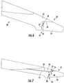
- Figs. 5 to 7 show enlarged views of a tooth 20 comprising a mechanical entrapment detection switch according to a first embodiment of the invention.
- Fig. 5 shows a perspective view of such a tooth 20 comprising a mechanical entrapment detection switch
- Fig. 6 shows a planar side view
- Fig. 7 shows a sectional view thereof.
- the tooth 20 comprises a main body 21 and a stationary part 22.
- the main body 21 is stationarily mounted to, or formed integrally with, a main body of the comb plate 16 (cf. Fig. 4 ), and the stationary part 22 is stationarily mounted to, or formed integrally with, the main body 21.
- the tooth 20 further comprises a movable element 24, which is movable with respect to the stationary part 22.
- the movable element 24 in particular is formed as sleeve 24 movably enclosing a tip portion 23 of the stationary part 22.
- the movable element 24 in particular is movable along a longitudinal direction of the tooth 20 parallel to the moving direction of the conveyance elements 14 when they pass the teeth 18, 20 of the comb plate 16.
- An elastic element 28 such as a spring, in particular a spiral spring is arranged between a rear end surface 25 of the movable element 24 and an opposing support surface 27 formed on the stationary part 22.
- the elastic element 28 urges the movable element 24 towards the end of the tooth 20 into a first position (initial position), as it is shown in Figs. 5 to 7 .
- Two electrical lines 32, 34 extend along the longitudinal direction of the tooth 20 into the tip portion 23.
- the two electrical lines 32, 34 are electrically connected by a connecting pin 30 extending transverse, in particular orthogonally, to the longitudinal direction through the stationary part 22 of the tooth 20.
- the movable element 24 In case of entrapment, i.e. when a foreign object, in particular parts clothing or a part of a human body, or a portion of a bent cleat 13 hits against the movable element 24, the movable element 24 is urged by the movement of the respective conveying element 14 to move against the elastic force of the elastic element 28 into a second position (to the left side in the orientation shown in Figs. 5 to 7 ) narrowing the gap 26 between the stationary part 22 and the movable element 24.
- the connecting pin 30 is moved from its connecting position shown in Fig. 7 , in which it electrically connects the first and second electrical lines 32, 34 with each other, into a non-connecting position, in which the connecting pin 30 does not electrically connect the electrical lines 32, 34 anymore.
- the electrical lines 32, 34 in combination with the connecting pin 30 form an electrical switch 36 providing a sensor 35, which is configured for detecting whether the movable element 24 is positioned in its first or second position.
- the described interruption of the electrical contact between the electrical lines 32, 34 may be detected by a detection circuit (not shown) which may issue an alarm signal and/or shut off the driving force applied to the conveyance elements 14 of the people conveyor 2 in order to prevent the entrapment from causing any (additional) harm or damage.
- the electrical lines 32, 34 are not connected to each other when the moving element 24 is in its first position (no entrapment), and the electrical lines 32, 34 are electrically connected to each other when the movable element 24 is moved from its first position towards its second position in case of an entrapment incident.
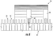
- Fig. 8 is similar to Fig. 4 and illustrates a tooth 40 comprising a mechanical entrapment detection switch extending into one of the grooves 15 formed on top of the tread plate 12.
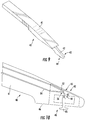
- Fig. 9 is similar to Fig. 5 and shows a perspective view of a tooth 40 comprising an entrapment switch according to a second embodiment of the invention.
- Fig. 10 shows a sectional view of the tooth 40.
- the tooth 40 according to the second embodiment also comprises a stationary part 42, which is stationarily mounted to, or formed integrally with, a main body 41 of the tooth 40.
- the main body 41 is stationarily mounted to, or formed integrally with, the main body of the comb plate 16.
- the tooth 40 also comprises a movable element 44, which in this embodiment is provided in the form of a movable pin 44.
- the movable pin 44 extends basically perpendicularly to the longitudinal direction, i.e. the moving direction of the conveyance elements 14 when passing the teeth 18, 20, 40 (cf. Fig. 2 ).
- the movable pin 44 in particular protrudes from a bottom surface 46 of the stationary part 42.
- a lower end of the movable pin 44 facing the tread plate 12 is formed as stamp 45 having a larger diameter than the rest of the movable pin 44. This increases the contact area between the movable pin 44 and a foreign object (not shown) in case of entrapment.
- the movable pin 44 is elastically supported by an elastic element 48 such as a (spiral) spring, which is arranged within the stationary part 42 of the tooth 40.
- the movable pin 44 is movable basically orthogonally to the moving direction of the conveyance elements 14 when passing the tooth 40.
- the movable pin 44 in particular is movable between a first position, in which it extends from the lower surface 46 of the tooth 40, and a second position, in which it is pushed upwards into the stationary part 42 of the tooth 40.
- At least two electrical lines 52, 54 extend through the tooth 40.
- the two electrical lines 52, 54 are not electrically connected to each other when the movable pin 44 is positioned in its first position when there is no entrapment.
- the movable pin 44 and in particular its lower stamp portion 45 contact a foreign element (not shown) or a bent cleat 13 of the tread plate 12. In consequence, the movable pin 44 is pushed upwards against the elastic force of the elastic element 48 into the stationary part 42 of the tooth 40.
- a portion 47 of the movable pin 44 electrically connects the two electrical lines 52, 54. This closes an electric circuit, which is detected by a detection unit (not shown) to which the electrical lines 52, 54 are connected.
- the detection unit may issue an alarm signal and/or prevent any further movement of the conveyance elements 14.
- the electrical lines 52, 54 in combination with the movable pin 44 form an electrical switch 56 providing a sensor 55, which is configured for detecting whether the movable element 44 is positioned in its first or second position.
- the electrical lines 52, 54 and the movable pin 44 may be configured such that the electrical lines 52, 54 are electrically connected with each other when the movable pin 44 is arranged in its first position (no entrapment), and that the electrical connection between the two electrical lines 52, 54 is interrupted when the movable pin 44 is moved from its first position towards a second position in case of entrapment. This interruption may be detected by the detection unit (not shown) to which the electrical lines 52, 54 are connected. The detection unit may issue an alarm signal and/or prevent any further movement of the conveyance elements 14.
Landscapes
- Escalators And Moving Walkways (AREA)
- Control Of Conveyors (AREA)
Abstract
A comb plate (16) for a people conveyor (2) comprises a plurality of teeth (18, 20), wherein at least one of the teeth (20) includes a mechanical entrapment detection switch which is configured for detecting an incident of entrapment at said at least one tooth (20).
Description
- The invention relates to a comb plate for a people conveyor and to a people conveyor comprising such a comb plate.
- People conveyors such as escalators and moving walkways usually comprise a conveyance band, which is configured for conveying passengers. The conveyance band extends and moves between two opposing landing zones. The conveyance band has a conveyance surface usually comprising cleats and grooves. A comb plate comprising a plurality of teeth extending into the grooves is provided at each of the landing zones.
- Entrapment of foreign objects, in particular cloths or parts of a human body, or bent cleats at the comb plates may cause safety issues of people conveyors.
- It therefore would be beneficial to provide a comb plate and a people conveyor which allow reliably detecting incidents of entrapment occurring at the comb plates.
- According to an embodiment of the invention, a comb plate for a people conveyor having a conveyance band, which is configured for conveying passengers, comprises a plurality of teeth configured to be oriented towards the conveyance band of the people conveyor in a configuration where the comb plate is installed in the people conveyor. At least one of the teeth includes a mechanical entrapment detection switch which is configured for detecting incidents of entrapment at said at least one tooth.
- Exemplary embodiments of the invention also include a people conveyor comprising a conveyance band, which is configured for conveying passengers, and at least one comb plate with a plurality of teeth oriented towards the conveyance band, wherein at least one of the teeth includes a mechanical entrapment detection switch which is configured for detecting an incident of entrapment at said at least one tooth. The conveyance band may comprise at least one tread surface with a plurality of grooves, and the teeth of the at least one comb plate may extend into said grooves.
- A comb plate comprising at least one tooth including an entrapment detection switch allows a reliable detection of entrapment incidents at the comb plate. It further allows to stop any further operation of the people conveyor in case an entrapment is detected preventing passengers from getting injured or the people conveyor from being (further) damaged.
- A number of optional features are set out in the following. These features may be realized in particular embodiments, alone or in combination with any of the other features.
- The at least one tooth may comprise a stationary part, which is stationary with respect to the comb plate, and a movable element, which is movable with respect to the stationary part between a first position and a second position. The at least one tooth may further comprise at least one sensor, which is configured for detecting whether the movable element is positioned in its first or second position.
- In such a configuration the combination of the stationary part, the movable element, and the at least one sensor provides a reliable entrapment detection switch allowing for a reliable detection of entrapment incidents at the comb plate without the need for additional assembly space.
- The at least one sensor may comprise two electrical lines which are not electrically connected to each other when the movable element is positioned in the first position and which are electrically connected to each other when the movable element is positioned in the second position. Two electrical lines, which are selectively electrically connectable to each other depending on the position of the movable element, provide a simple but appropriate sensor for detection of the position of the movable element with respect to the stationary part.
- The movable element in particular may be configured for electrically connecting the two electrical lines by itself. Alternatively, the movable element may be configured for activating an electrical switch for connecting the two electrical lines.
- The at least one tooth may comprise at least one elastic element which is configured for urging the movable element towards one of the first and second positions in order to move the movable element in a well-defined initial position in case there is no entrapment. The at least one elastic element may be a spring, in particular a linearly acting spring such as a spiral spring, which is arranged between the stationary part and the movable element.
- The movable element may be or may comprise a sleeve enclosing at least a portion of the stationary part. A sleeve enclosing at least a portion of the stationary part provides a mechanically strong and stable movable element, which does not need any additional assembly space. The sleeve may be configured to move in a sliding motion with respect to the stationary part. The sleeve in particular may be guided along the stationary part by means of appropriate guiding elements, such as grooves which are formed on one of the stationary part and the movable element and interact with corresponding protrusions formed on the other one of the stationary part and the movable element.
- As an alternative to the sleeve, the movable element may comprise a pin which extends from the stationary part and which is movable with respect to the stationary part. A portion of the pin may extend inside the stationary part where it is protected from damage.
- The movable element may be made partly of metal and/or plastic. Metal provides a very strong movable element; plastic provides a movable element having a low weight.
- More than one of the teeth of the comb plate may include a mechanical entrapment detection switch as described herein, respectively, in order to reliably detect entrapment incidents over the whole width of the comb plate.
- The at least one movable element may be movable in a direction which is parallel to the moving direction of the conveyance band when it passes the teeth of the comb plate. Thus, the movable element, when moved, moves parallel to the conveyance band when it passes the teeth.
- In an alternative embodiment, the at least one movable element may be movable in a direction which is inclined, in particular oriented orthogonally, to the moving direction of the conveyance band when it passes the teeth of the comb plate. Thus, the movable element, when moved, does not move parallel to the conveyance band when it passes the teeth.
- In the following exemplary embodiments of the invention are described with reference to the enclosed figures.
-
Fig. 1 shows a perspective view of a portion of a people conveyor according to an exemplary embodiment of the invention. -
Fig. 2 shows an enlarged perspective view of an upper landing zone of the people conveyor. -
Fig. 3 shows a perspective view of a conveyance element and a section of a comb plate according to an exemplary embodiment of the invention. -
Fig. 4 shows an enlarged sectional view of the conveyance element and the section of the comb plate shown inFig. 3 . -
Fig. 5 shows a perspective view of a tooth comprising a mechanical entrapment detection switch according to an exemplary embodiment of the invention. -
Fig. 6 shows a planar side view of the tooth shown inFig. 5 . -
Fig. 7 shows a sectional view of the tooth shown inFigs. 5 and6 . -
Fig. 8 shows an enlarged sectional view of a conveyance element and a section of a comb plate according to another exemplary embodiment of the invention. -
Fig. 9 shows a perspective view of a tooth comprising a mechanical entrapment detection switch according to the other exemplary embodiment of the invention. -
Fig. 10 shows a sectional view of the tooth shown inFig. 9 . -
Fig. 1 shows a perspective view of a people conveyor 2 according to an exemplary embodiment of the invention. - The people conveyor 2 shown in
Fig. 1 is an escalator comprising a plurality ofsteps 14. The people conveyor 2 comprises atruss 4 extending in a (longitudinal) conveyance direction between a lower landing zone 3 comprising a floor plate 6 and a corresponding upper landing zone 9 (seeFig. 2 ), which is not shown inFig. 1 . - The
truss 4 supports a chain of conveyance elements (steps) 14 forming aconveyance band 8, which in the case of an escalator is a chain ofsteps 14, and twobalustrades 5 extending parallel to theconveyance band 8. Thebalustrades 5 reside laterally at both sides of theconveyance band 8 respectively supporting a movinghandrail 7. - Although the people conveyor 2 shown in
Fig. 1 is an escalator comprising a plurality ofsteps 14, the skilled person will understand that the ideas and principles described in the following may be applied to horizontal and inclined moving walkways comprising pallets instead ofsteps 14 and to any other types of people conveyors 2 as well. -
Fig. 2 shows an enlarged perspective view of theupper landing zone 9, which is not shown inFig. 1 . -
Fig. 2 in particular illustrates that an upper surface of each of theconveyance elements 14 is provided with a plurality ofalternating grooves 15 andcleats 13 extending in the conveyance direction. - A
comb plate 16 is arranged next to floor plate 6 on the side of the floor plate 6 facing theconveyance band 8. Thecomb plate 16 comprises a plurality ofteeth 18 extending parallel to the conveyance direction. Theteeth 18 are in a staggered relation with thecleats 13 of theconveyance elements 14 and extend into thegrooves 15 formed on the upper surfaces of theconveyance elements 14. -
Fig. 3 shows a perspective view of a conveyance element, in this case a step, 14 of the people conveyor 2. Theconveyance element 14 comprises aplanar tread plate 12 and anarcuate riser portion 11 extending basically orthogonally from thetread plate 12. -
Fig. 3 further shows a section of acomb plate 16 with twoteeth comb plate 16. Theteeth teeth grooves 15 formed within or on thetread plate 12. - Although only a section of the
comb plate 16 is shown inFig. 3 , the skilled person will understand that thecomb plate 16 usually extends over the whole width of theconveyance element 14 and comprises a plurality ofteeth grooves 15 formed on thetread plate 12 as it is shown inFig. 2 . -
Fig. 4 shows an enlarged sectional view of theconveyance element 14 and thecomb plate 16 shown inFig. 3 .Fig. 4 in particular illustrates the spatial relation betweenteeth grooves 15 of thetread plate 12. - In the exemplary embodiment shown in
Figs. 3 and4 , thetooth 18 shown on the right side of the respective figure is aconventional tooth 18, and thetooth 20 shown on the left side is provided with a mechanical entrapment detection switch according to an exemplary embodiment of the invention. Although only onetooth 20 comprising such an entrapment detection switch is shown inFigs. 3 and4 , the skilled person will understand that thecomb plate 16 may be provided withadditional teeth 20 comprising such an entrapment detection switch, respectively. -
Figs. 5 to 7 show enlarged views of atooth 20 comprising a mechanical entrapment detection switch according to a first embodiment of the invention. -
Fig. 5 shows a perspective view of such atooth 20 comprising a mechanical entrapment detection switch,Fig. 6 shows a planar side view andFig. 7 shows a sectional view thereof. - The
tooth 20 comprises amain body 21 and astationary part 22. Themain body 21 is stationarily mounted to, or formed integrally with, a main body of the comb plate 16 (cf.Fig. 4 ), and thestationary part 22 is stationarily mounted to, or formed integrally with, themain body 21. - The
tooth 20 further comprises amovable element 24, which is movable with respect to thestationary part 22. Themovable element 24 in particular is formed assleeve 24 movably enclosing atip portion 23 of thestationary part 22. - The
movable element 24 in particular is movable along a longitudinal direction of thetooth 20 parallel to the moving direction of theconveyance elements 14 when they pass theteeth comb plate 16. - An
elastic element 28, such as a spring, in particular a spiral spring is arranged between arear end surface 25 of themovable element 24 and an opposingsupport surface 27 formed on thestationary part 22. Theelastic element 28 urges themovable element 24 towards the end of thetooth 20 into a first position (initial position), as it is shown inFigs. 5 to 7 . - Two
electrical lines 32, 34 (seeFig. 7 ) extend along the longitudinal direction of thetooth 20 into thetip portion 23. When themovable element 24 is positioned in the first position depicted inFigs. 5 and6 , the twoelectrical lines pin 30 extending transverse, in particular orthogonally, to the longitudinal direction through thestationary part 22 of thetooth 20. - In case of entrapment, i.e. when a foreign object, in particular parts clothing or a part of a human body, or a portion of a
bent cleat 13 hits against themovable element 24, themovable element 24 is urged by the movement of the respective conveyingelement 14 to move against the elastic force of theelastic element 28 into a second position (to the left side in the orientation shown inFigs. 5 to 7 ) narrowing thegap 26 between thestationary part 22 and themovable element 24. - Due to this movement of the
movable element 24, the connectingpin 30 is moved from its connecting position shown inFig. 7 , in which it electrically connects the first and secondelectrical lines pin 30 does not electrically connect theelectrical lines electrical lines pin 30 form anelectrical switch 36 providing asensor 35, which is configured for detecting whether themovable element 24 is positioned in its first or second position. - The described interruption of the electrical contact between the
electrical lines conveyance elements 14 of the people conveyor 2 in order to prevent the entrapment from causing any (additional) harm or damage. - In an alternative configuration, which is not explicitly depicted in the figures, the
electrical lines element 24 is in its first position (no entrapment), and theelectrical lines movable element 24 is moved from its first position towards its second position in case of an entrapment incident. - An alternative embodiment of a
tooth 40 comprising a mechanical entrapment detection switch is described in the following with reference toFigs. 8 to 10 . -
Fig. 8 is similar toFig. 4 and illustrates atooth 40 comprising a mechanical entrapment detection switch extending into one of thegrooves 15 formed on top of thetread plate 12. -
Fig. 9 is similar toFig. 5 and shows a perspective view of atooth 40 comprising an entrapment switch according to a second embodiment of the invention.Fig. 10 shows a sectional view of thetooth 40. - The
tooth 40 according to the second embodiment also comprises astationary part 42, which is stationarily mounted to, or formed integrally with, amain body 41 of thetooth 40. Themain body 41 is stationarily mounted to, or formed integrally with, the main body of thecomb plate 16. - The
tooth 40 also comprises amovable element 44, which in this embodiment is provided in the form of amovable pin 44. Themovable pin 44 extends basically perpendicularly to the longitudinal direction, i.e. the moving direction of theconveyance elements 14 when passing theteeth Fig. 2 ). Themovable pin 44 in particular protrudes from abottom surface 46 of thestationary part 42. - In the embodiment shown in
Figs. 8 to 10 , a lower end of themovable pin 44 facing thetread plate 12 is formed asstamp 45 having a larger diameter than the rest of themovable pin 44. This increases the contact area between themovable pin 44 and a foreign object (not shown) in case of entrapment. - The
movable pin 44 is elastically supported by anelastic element 48 such as a (spiral) spring, which is arranged within thestationary part 42 of thetooth 40. Themovable pin 44 is movable basically orthogonally to the moving direction of theconveyance elements 14 when passing thetooth 40. Themovable pin 44 in particular is movable between a first position, in which it extends from thelower surface 46 of thetooth 40, and a second position, in which it is pushed upwards into thestationary part 42 of thetooth 40. - As in the first embodiment, at least two
electrical lines tooth 40. In the embodiment shown inFig. 10 , the twoelectrical lines movable pin 44 is positioned in its first position when there is no entrapment. - In case of entrapment, the
movable pin 44 and in particular itslower stamp portion 45 contact a foreign element (not shown) or abent cleat 13 of thetread plate 12. In consequence, themovable pin 44 is pushed upwards against the elastic force of theelastic element 48 into thestationary part 42 of thetooth 40. - As a result, a
portion 47 of themovable pin 44 electrically connects the twoelectrical lines electrical lines conveyance elements 14. Thus, theelectrical lines movable pin 44 form anelectrical switch 56 providing asensor 55, which is configured for detecting whether themovable element 44 is positioned in its first or second position. - Alternatively, the
electrical lines movable pin 44 may be configured such that theelectrical lines movable pin 44 is arranged in its first position (no entrapment), and that the electrical connection between the twoelectrical lines movable pin 44 is moved from its first position towards a second position in case of entrapment. This interruption may be detected by the detection unit (not shown) to which theelectrical lines conveyance elements 14. - While the invention has been described with reference to exemplary embodiments, it will be understood by those skilled in the art that various changes may be made and equivalents may be substituted for elements thereof without departing from the scope of the invention. In addition many modifications may be made to adopt a particular situation or material to the teachings of the invention without departing from the essential scope thereof. Therefore, it is intended that the invention not be limited to the particular embodiment disclosed, but that the invention include all embodiments falling within the scope of the dependent claims.
-
- 2
- people conveyor
- 3
- lower landing zone
- 4
- truss
- 5
- balustrade
- 6
- floor plate
- 7
- handrail element
- 8
- conveyance band
- 9
- upper landing zone
- 11
- riser portion
- 12
- tread plate
- 13
- cleat
- 14
- conveyance element (step)
- 15
- groove
- 16
- comb plate
- 18
- tooth
- 20
- tooth
- 21
- main body
- 22
- stationary part
- 23
- tip portion
- 24
- movable element / sleeve
- 25
- rear end surface
- 26
- gap
- 27
- support surface
- 28
- elastic element / spring
- 30
- connecting pin
- 32
- electrical line
- 34
- electrical line
- 35
- sensor
- 36
- electrical switch
- 40
- tooth
- 41
- main body
- 42
- stationary part
- 43
- tip portion
- 44
- movable element / movable pin
- 45
- stamp
- 46
- bottom surface
- 47
- portion of the movable pin
- 48
- elastic element / spring
- 52
- electrical line
- 54
- electrical line
- 55
- sensor
- 56
- electrical switch
Claims (15)
- Comb plate (16) for a people conveyor (2), the comb plate (16) comprising a plurality of teeth (18, 20; 40), wherein at least one of the teeth (20; 40) includes a mechanical entrapment detection switch which is configured for detecting an incident of entrapment at said at least one tooth (20; 40).
- Comb plate (16) according to claim 1, wherein the at least one of the teeth (20; 40) comprises a stationary part (22; 42), which is stationary with respect to the comb plate (16), and a movable element (24; 44), which is movable with respect to the stationary part (22; 42) between a first position and a second position.
- Comb plate (16) according to claim 2, wherein the at least one tooth (20; 40) comprises at least one sensor (35; 55), which is configured for detecting whether the movable element (24; 44) is positioned in its first or second position.
- Comb plate (16) according to claim 3, wherein the at least one sensor (35; 55) comprises two electrical lines (32, 34; 52, 54) which are electrically connected to each other when the movable element (24; 44) is positioned in the second position, and which are not electrically connected to each other, when the movable element (24; 44) is positioned in the first position.
- Comb plate (16) according to claim 4, wherein the movable element (24; 44) itself is configured for electrically connecting the two electrical lines (32, 34; 52, 54), or wherein the movable element (24; 44) is configured for activating an electrical switch (36; 56) connecting the two electrical lines (32, 34; 52, 54).
- Comb plate (16) according to any of claims 2 to 5, wherein the at least one tooth (20; 40) further comprises at least one elastic element (28; 48) which is configured for urging the movable element (24; 44) towards one of the first and second positions.
- Comb plate (16) according to any of claims 2 to 6, wherein the movable element (24) comprises a sleeve (24) which is enclosing at least a portion of the stationary part (22).
- Comb plate (16) according to claim 7, wherein the sleeve (24) is configured to move in a sliding motion with respect to the stationary part (22).
- Comb plate (16) according to any of claims 2 to 8, wherein the movable element (44) comprises a movable pin (44) extending from the stationary part (42).
- Comb plate (16) according to any of claims 2 to 9, wherein the movable element (24; 44) is made of metal and/or plastic.
- Comb plate (16) according to any of the previous claims, wherein a plurality of the teeth (20; 40) of the comb plate (16) include a mechanical entrapment detection switch, respectively.
- People conveyor comprising at least one conveyance band (8), which is configured for conveying passengers, and at least one comb plate (16) according to any of the previous claims.
- People conveyor according to claim 12, wherein the conveyance band (8) comprises at least one tread surface (12) with a plurality of grooves (15), and wherein the teeth (18, 20; 40) of the at least one comb plate (16) extend into said grooves (15).
- People conveyor according to claim 12 ot 13, wherein the at least one movable element (24) is movable parallel to the moving direction of the conveyance band (8) when it passes the teeth (18, 20; 40) of the comb plate (16).
- People conveyor according to any of claims 12 to 14, wherein the at least one movable element (44) is movable in a direction which is inclined, in particular oriented orthogonally, to the moving direction of the conveyance band (8) when passing the teeth (20; 40) of the comb plate (16).
Priority Applications (3)
| Application Number | Priority Date | Filing Date | Title |
|---|---|---|---|
| EP17197053.6A EP3473579A1 (en) | 2017-10-18 | 2017-10-18 | Comb plate and people conveyor |
| US16/160,557 US20190112162A1 (en) | 2017-10-18 | 2018-10-15 | Comb plate and people conveyor |
| CN201811215296.3A CN109678041A (en) | 2017-10-18 | 2018-10-18 | Fishback and personnel's conveyer |
Applications Claiming Priority (1)
| Application Number | Priority Date | Filing Date | Title |
|---|---|---|---|
| EP17197053.6A EP3473579A1 (en) | 2017-10-18 | 2017-10-18 | Comb plate and people conveyor |
Publications (1)
| Publication Number | Publication Date |
|---|---|
| EP3473579A1 true EP3473579A1 (en) | 2019-04-24 |
Family
ID=60138286
Family Applications (1)
| Application Number | Title | Priority Date | Filing Date |
|---|---|---|---|
| EP17197053.6A Withdrawn EP3473579A1 (en) | 2017-10-18 | 2017-10-18 | Comb plate and people conveyor |
Country Status (3)
| Country | Link |
|---|---|
| US (1) | US20190112162A1 (en) |
| EP (1) | EP3473579A1 (en) |
| CN (1) | CN109678041A (en) |
Families Citing this family (3)
| Publication number | Priority date | Publication date | Assignee | Title |
|---|---|---|---|---|
| CN112938731B (en) * | 2021-01-28 | 2023-04-14 | 陈子格 | Open-air staircase of passenger footbridge |
| US20250042699A1 (en) * | 2023-08-02 | 2025-02-06 | Otis Elevator Company | Escalator entrapment detection system |
| US20250059004A1 (en) * | 2023-08-14 | 2025-02-20 | Otis Elevator Company | Escalator combplate retraction device |
Citations (4)
| Publication number | Priority date | Publication date | Assignee | Title |
|---|---|---|---|---|
| FR1413571A (en) * | 1964-11-05 | 1965-10-08 | Schweiz Wagons Aufzuegefab | Improvements made to escalators |
| US20030127301A1 (en) * | 2002-01-10 | 2003-07-10 | Richard Lauch | Escalator combteeth force detector |
| CN205187620U (en) * | 2015-10-30 | 2016-04-27 | 株式会社日立制作所 | Passenger conveying equipment and its combs |
| CN106586797A (en) * | 2016-12-29 | 2017-04-26 | 袁江 | Escalator, automatic passenger conveyor and comb tooth device |
Family Cites Families (9)
| Publication number | Priority date | Publication date | Assignee | Title |
|---|---|---|---|---|
| GB1159589A (en) * | 1966-12-02 | 1969-07-30 | Richard Sutcliffe Engineering | Safety Device for a Conveyor |
| US4800998A (en) * | 1988-01-21 | 1989-01-31 | Otis Elevator Company | Escalator comb safety device |
| US6976571B2 (en) * | 2000-07-31 | 2005-12-20 | Otis Elevator Company | Comb plate for people mover |
| JP3889257B2 (en) * | 2001-09-28 | 2007-03-07 | 株式会社日立製作所 | Passenger conveyor |
| JP3935699B2 (en) * | 2001-10-10 | 2007-06-27 | 株式会社日立製作所 | Passenger conveyor steps |
| US7334672B2 (en) * | 2005-08-12 | 2008-02-26 | Motor Drives & Controls, Inc. | Method for detecting faults in a combplate and sensor combplate |
| CN201077708Y (en) * | 2007-08-20 | 2008-06-25 | 杭州新马电梯有限公司 | Combs safety installation |
| JP5695587B2 (en) * | 2012-03-01 | 2015-04-08 | 株式会社日立製作所 | Passenger conveyor |
| WO2014015870A2 (en) * | 2012-07-24 | 2014-01-30 | Thyssenkrupp Fahrtreppen Gmbh | Escalator or moving walkway |
-
2017
- 2017-10-18 EP EP17197053.6A patent/EP3473579A1/en not_active Withdrawn
-
2018
- 2018-10-15 US US16/160,557 patent/US20190112162A1/en not_active Abandoned
- 2018-10-18 CN CN201811215296.3A patent/CN109678041A/en active Pending
Patent Citations (4)
| Publication number | Priority date | Publication date | Assignee | Title |
|---|---|---|---|---|
| FR1413571A (en) * | 1964-11-05 | 1965-10-08 | Schweiz Wagons Aufzuegefab | Improvements made to escalators |
| US20030127301A1 (en) * | 2002-01-10 | 2003-07-10 | Richard Lauch | Escalator combteeth force detector |
| CN205187620U (en) * | 2015-10-30 | 2016-04-27 | 株式会社日立制作所 | Passenger conveying equipment and its combs |
| CN106586797A (en) * | 2016-12-29 | 2017-04-26 | 袁江 | Escalator, automatic passenger conveyor and comb tooth device |
Also Published As
| Publication number | Publication date |
|---|---|
| CN109678041A (en) | 2019-04-26 |
| US20190112162A1 (en) | 2019-04-18 |
Similar Documents
| Publication | Publication Date | Title |
|---|---|---|
| JP5674024B2 (en) | Passenger conveyor safety device | |
| US20190112162A1 (en) | Comb plate and people conveyor | |
| TWI843835B (en) | Side monitoring device for a passenger transport system | |
| FI127155B (en) | Monitoring arrangement for a passenger carrier | |
| FI127156B (en) | Monitoring arrangement for a passenger carrier | |
| JP2010149957A (en) | Footstep displacement detection device for escalator | |
| JPH11171457A (en) | Entry and exit safety device for man conveyor | |
| CN108137289B (en) | Mankind's transport device with monitoring device | |
| US20190352141A1 (en) | Belt safety device and people conveyor with a belt safety device | |
| US20190112160A1 (en) | Balustrade for a people conveyor | |
| JP5797800B2 (en) | Passenger conveyor | |
| JP4855991B2 (en) | Passenger conveyor device tread member displacement regulation structure | |
| CN205187620U (en) | Passenger conveying equipment and its combs | |
| JPH04153195A (en) | Man conveyor platform safety device | |
| JP6334445B2 (en) | Passenger conveyor | |
| KR100858783B1 (en) | Comb Safety Device for Moving Walkway | |
| EP3309108B1 (en) | People conveyor and method of operating a people conveyor | |
| JP2014065559A (en) | Passenger conveyor | |
| JP2012106848A (en) | Passenger conveyor | |
| JP2013193849A (en) | Passenger conveyer safety device | |
| JP6367431B1 (en) | Passenger conveyor | |
| JP6454289B2 (en) | Passenger conveyor | |
| HK40111071A (en) | Passenger conveying device and method for safely operating a passenger conveying device | |
| JP2013014385A (en) | Safety device of passenger conveyor | |
| JP2017114595A (en) | Passenger conveyor |
Legal Events
| Date | Code | Title | Description |
|---|---|---|---|
| PUAI | Public reference made under article 153(3) epc to a published international application that has entered the european phase |
Free format text: ORIGINAL CODE: 0009012 |
|
| AK | Designated contracting states |
Kind code of ref document: A1 Designated state(s): AL AT BE BG CH CY CZ DE DK EE ES FI FR GB GR HR HU IE IS IT LI LT LU LV MC MK MT NL NO PL PT RO RS SE SI SK SM TR |
|
| AX | Request for extension of the european patent |
Extension state: BA ME |
|
| STAA | Information on the status of an ep patent application or granted ep patent |
Free format text: STATUS: THE APPLICATION IS DEEMED TO BE WITHDRAWN |
|
| 18D | Application deemed to be withdrawn |
Effective date: 20191025 |