EP3473542A1 - Rotor assembly and unmanned aerial vehicle - Google Patents
Rotor assembly and unmanned aerial vehicle Download PDFInfo
- Publication number
- EP3473542A1 EP3473542A1 EP16921046.5A EP16921046A EP3473542A1 EP 3473542 A1 EP3473542 A1 EP 3473542A1 EP 16921046 A EP16921046 A EP 16921046A EP 3473542 A1 EP3473542 A1 EP 3473542A1
- Authority
- EP
- European Patent Office
- Prior art keywords
- limiting
- propeller
- rotor
- engaging
- locking
- Prior art date
- Legal status (The legal status is an assumption and is not a legal conclusion. Google has not performed a legal analysis and makes no representation as to the accuracy of the status listed.)
- Withdrawn
Links
Images




Classifications
-
- B—PERFORMING OPERATIONS; TRANSPORTING
- B64—AIRCRAFT; AVIATION; COSMONAUTICS
- B64C—AEROPLANES; HELICOPTERS
- B64C11/00—Propellers, e.g. of ducted type; Features common to propellers and rotors for rotorcraft
- B64C11/02—Hub construction
-
- B—PERFORMING OPERATIONS; TRANSPORTING
- B64—AIRCRAFT; AVIATION; COSMONAUTICS
- B64C—AEROPLANES; HELICOPTERS
- B64C27/00—Rotorcraft; Rotors peculiar thereto
- B64C27/04—Helicopters
- B64C27/12—Rotor drives
- B64C27/14—Direct drive between power plant and rotor hub
-
- B—PERFORMING OPERATIONS; TRANSPORTING
- B64—AIRCRAFT; AVIATION; COSMONAUTICS
- B64C—AEROPLANES; HELICOPTERS
- B64C27/00—Rotorcraft; Rotors peculiar thereto
- B64C27/32—Rotors
- B64C27/46—Blades
- B64C27/473—Constructional features
-
- B—PERFORMING OPERATIONS; TRANSPORTING
- B64—AIRCRAFT; AVIATION; COSMONAUTICS
- B64C—AEROPLANES; HELICOPTERS
- B64C11/00—Propellers, e.g. of ducted type; Features common to propellers and rotors for rotorcraft
- B64C11/02—Hub construction
- B64C11/04—Blade mountings
-
- B—PERFORMING OPERATIONS; TRANSPORTING
- B64—AIRCRAFT; AVIATION; COSMONAUTICS
- B64D—EQUIPMENT FOR FITTING IN OR TO AIRCRAFT; FLIGHT SUITS; PARACHUTES; ARRANGEMENT OR MOUNTING OF POWER PLANTS OR PROPULSION TRANSMISSIONS IN AIRCRAFT
- B64D27/00—Arrangement or mounting of power plants in aircraft; Aircraft characterised by the type or position of power plants
- B64D27/02—Aircraft characterised by the type or position of power plants
- B64D27/24—Aircraft characterised by the type or position of power plants using steam or spring force
-
- B—PERFORMING OPERATIONS; TRANSPORTING
- B64—AIRCRAFT; AVIATION; COSMONAUTICS
- B64D—EQUIPMENT FOR FITTING IN OR TO AIRCRAFT; FLIGHT SUITS; PARACHUTES; ARRANGEMENT OR MOUNTING OF POWER PLANTS OR PROPULSION TRANSMISSIONS IN AIRCRAFT
- B64D27/00—Arrangement or mounting of power plants in aircraft; Aircraft characterised by the type or position of power plants
- B64D27/40—Arrangements for mounting power plants in aircraft
-
- B—PERFORMING OPERATIONS; TRANSPORTING
- B64—AIRCRAFT; AVIATION; COSMONAUTICS
- B64U—UNMANNED AERIAL VEHICLES [UAV]; EQUIPMENT THEREFOR
- B64U30/00—Means for producing lift; Empennages; Arrangements thereof
- B64U30/20—Rotors; Rotor supports
- B64U30/29—Constructional aspects of rotors or rotor supports; Arrangements thereof
-
- B—PERFORMING OPERATIONS; TRANSPORTING
- B64—AIRCRAFT; AVIATION; COSMONAUTICS
- B64U—UNMANNED AERIAL VEHICLES [UAV]; EQUIPMENT THEREFOR
- B64U50/00—Propulsion; Power supply
- B64U50/10—Propulsion
- B64U50/19—Propulsion using electrically powered motors
-
- B—PERFORMING OPERATIONS; TRANSPORTING
- B64—AIRCRAFT; AVIATION; COSMONAUTICS
- B64C—AEROPLANES; HELICOPTERS
- B64C2211/00—Modular constructions of airplanes or helicopters
-
- B—PERFORMING OPERATIONS; TRANSPORTING
- B64—AIRCRAFT; AVIATION; COSMONAUTICS
- B64U—UNMANNED AERIAL VEHICLES [UAV]; EQUIPMENT THEREFOR
- B64U10/00—Type of UAV
- B64U10/10—Rotorcrafts
- B64U10/13—Flying platforms
- B64U10/14—Flying platforms with four distinct rotor axes, e.g. quadcopters
Definitions
- the present invention generally relates to the field of aircraft, and more particularly relates to a rotor-wing assembly and an unmanned aerial vehicle.
- an unmanned aerial vehicle includes a motor and a locking member arranged on the motor. After rotating relative to the motor, the locking member engages with a locking catch of the propeller of the UAV, thus restricting the movement of the propeller with respect to the motor and facilitating disassembly and assembly of the propeller. However, due to the vibration generated during flight of the UAV, the locking member and the propeller are disengaged, which causes the propeller to fly off the motor and affects the normal flight of the UAV.
- the present invention aims to at least solve one of the technical problems existing in the existing technologies. To this end, the present invention needs to provide a rotor-wing assembly and a UAV.
- the rotor-wing assembly disclosed in the embodiments of the present invention includes motors, propellers, and connection assemblies.
- the motor includes a rotating portion.
- the connection assembly includes a locking member and a reinforcing member disposed between the propeller and the motor.
- the locking member locks the propeller to the rotating portion.
- a first end of the reinforcing member is mounted on the rotating portion.
- a second end of the reinforcing member opposite to the first end engages with the locking member for reinforcing the locking member to lock the propeller on the rotating portion.
- the rotating portion is formed with a first position-limiting structure.
- the first end of the reinforcing member is formed with a second position-limiting structure.
- the propeller is in a locked state.
- the first position-limiting structure is coupled with the second position-limiting structure, which allows the first end of the reinforcing member to be fixed on the rotating portion.
- the locking member can rotate relative to the propeller about the rotation axis of the propeller.
- the first position-limiting structure is a position-limiting block and the second position-limiting structure is a position-limiting groove capable of engaging with the position-limiting block, and/or the first position-limiting structure is a position-limiting groove and the second position-limiting structure is a position-limiting block capable of engaging with the position-limiting groove.
- the position-limiting groove extends in the circumferential direction of the propeller disk formed by rotation of the propeller.
- the rotating portion is formed with a guide-rail groove extending in the circumferential direction of the propeller disk formed by rotation of the propeller.
- the locking member includes a mounting portion mounted on the rotating portion and a guiding portion extending from the mounting portion in the direction away from the propeller.
- the guiding portion is coupled with the guide-rail groove for guiding the locking member to rotate about the rotation axis.
- the guiding portion includes a guiding section connected with the mounting portion and a holding section connected with the guiding section.
- the guiding section is located in the guide-rail groove, and the holding section is clamped on the rotating portion to prevent the locking member from being separated from the rotating portion.
- the guide-rail groove connects with the position-limiting groove, and the position-limiting block can move from the position-limiting groove into the position-limiting groove, such that the locking member can rotate relative to the propeller about the rotation axis.
- the locking member also includes a locking catch extending from the mounting portion toward the propeller.
- the propeller includes a hub, one or more blades disposed on the peripheral wall of the hub, and a first locking block disposed on the peripheral wall and coupled with the locking catch. When the propeller is locked, the locking catch is connected to the first locking block and the second end of the reinforcing member engages with the locking catch.
- the end of the locking catch connected with the first locking block is formed with a second locking block coupled with the first locking block.
- the locking member locks the propeller by engaging the second locking block with the first locking block.
- two mutually coupled surfaces of the first locking block and the second locking block are both inclined surfaces tilted at a predetermined angle relative to the rotation axis of the propeller. In the direction of the rotation axis, the side of the surface near the rotation axis is closer to the motor than the side away from the rotation axis.
- the two mutually coupled surfaces of the first locking block and the second locking block are engaged with each other in an interference-fit manner.
- the second locking block includes a top surface, a first side surface, and a second side surface opposite to the first side surface.
- the first side surface connected with the top surface is adjacent and opposite to the first side surface.
- the second end of the reinforcing member is formed with an engaging hook.
- the engaging hook includes an engaging surface and the engaging surface engages on the top surface.
- the engaging hook includes two engaging surfaces connected with each other at an angle to each other. The two engaging surfaces engage on the top surface and the first side surface, respectively.
- the top surface is provided with an engaging hole.
- the engaging hook includes an engaging portion and a contact portion. The engaging portion engages in the engaging hole, and the contact portion is in contact with the top surface.
- the top surface is provided with a recess.
- An engaging hole is formed at the bottom of the recess.
- the engaging hook includes an engaging portion and a contact portion connected with each other at an angle to each other. The engaging portion engages in the engaging hole and the contact portion is in contact with the bottom of the recess.
- the second side surface is provided with an engaging hole and the engaging hook engages in the engaging hole.
- the reinforcing member further includes a connection arm connecting the second position-limiting structure and the engaging hook.
- the connection arm is made of an elastic material.
- the number of the blades is two.
- the first locking block is disposed between the two blades.
- a space is formed between the first locking block and one of the blades, which allows the locking catch to pass through.
- connection assembly further includes a connection member connecting the propeller and the rotating portion.
- the connection member can be detachably mounted the locking member.
- connection member includes a connection plate and a position-limiting shaft extending from the connection plate to the propeller.
- the connection plate holds against the locking member.
- the position-limiting shaft is connected to the propeller and can restrict the rotation of the propeller with respect to the connection member.
- connection member further includes a reinforcing block extending from the connection plate to the hub.
- a reinforcing block extending from the connection plate to the hub.
- One side of the hub facing the rotating portion is provided with a mounting hole corresponding to the reinforcing block.
- the reinforcing block is mounted in the mounting hole.
- connection member further includes one or more position-limiting posts extending from the connection plate to the rotating portion.
- the one or more position-limiting posts are connected to the rotating portion by passing through the locking member, which can restrict the rotation of the connection member relative to the rotating portion.
- the rotating portion includes an end surface opposite to the connection member.
- One or more position-limiting holes are formed on the end surface.
- the one or more position-limiting posts engage in the one or more position-limiting holes.
- the one or more position-limiting posts are of a polygonal shape, an oblong shape, or an elliptical shape.
- the number of the position-limiting posts is at least two.
- the position-limiting posts correspond to the position-limiting holes. At least two position-limiting posts are disposed in the corresponding position-limiting holes.
- At least two of the position-limiting posts are arranged symmetrically about the rotation axis.
- the UAV disclosed in the embodiments of the present invention includes the rotor-wing assembly of any foregoing embodiments.
- the rotor-wing assembly and the UAV disclosed in the embodiments of the present invention can prevent the propeller from flying off the motor of the UAV, due to the reinforcing member that can reinforce the locking member to lock the propeller on the rotating portion, thereby ensuring the normal flight of the UAV.
- first and second are used for descriptive purposes only, which cannot be construed as indicating or implying a relative importance, or implicitly specifying the number of the indicated technical features.
- the features defined with “first” and “second” may explicitly or implicitly include one or more features.
- a plurality of' means two or more than two, unless specifically stated otherwise.
- the terms “mounting,” “joining,” “connection” should be understood in a broad sense, such as, a fixed connection, a detachable connection, or an integral connection; a mechanical connection, an electrical connection, or a communicative connection; a direct connection, an indirect connection through an intermediate medium, an internal connection of two elements, or an interaction of two elements.
- the specific meanings of the foregoing terms in the present invention can be understood on a case-by-case basis.
- the unmanned aerial vehicle (UAV) 100 of the present invention is a rotor-wing UAV.
- the UAV 100 can fly and hover in the air to perform specific tasks, such as flight, tracking, monitoring, exploration, search and rescue, sowing, spraying pesticides, firefighting, and aerial photography.
- the UAV 100 may be equipped with modules having predetermined functions, such as a sensor, a photographing device, a medical kit, to implement specific functions.
- the UAV 100 of the present invention includes a fuselage 10, one or more arms 20 and rotor-wing assemblies 30.
- the one or more arms 20 are installed on the fuselage 10.
- the one or more rotor-wing assemblies 30 are installed on the one or more arms 20 and arranged around the fuselage 10.
- the UAV 100 may be a quad-rotor type UAV, and correspondingly the number of the rotor-wing assemblies 30 may be four.
- the four rotor-wing assemblies 30 may be centrally symmetrical about the vertical central axis of the fuselage 10 for balancing the UAV 100 during flight.
- the number of the rotor-wing assemblies 30 may be set as other numbers according to actual needs.
- the number of the one or more rotor-wing assemblies 30 may be one, two, three, six, eight, etc.
- the fuselage 10 may serve as a carrier of the UAV 100.
- Components, such as sensors, circuit boards, processors, communication modules, and batteries, may be carried outside and/or inside the fuselage 10.
- the fuselage 10 includes a housing shell 11.
- a housing space of accommodating the foregoing components may be formed inside of the housing shell 11.
- the housing shell 11 may be streamlined, which can reduce air resistance during flight.
- the housing shell 11 may have another shape, such as a polygonal shape, a circular shape, an elliptical shape. It can be understood that the housing shell 11 may also be omitted and the fuselage 10 may be formed only by overlapping brackets.
- the arm 20 may support and allow the rotor-wing assembly 30 to surround the fuselage 10 in a predetermined pattern.
- the number of the arms 20 is two.
- Each arm 20 supports two rotor-wing assemblies 30 and includes a main arm 21 and a branch arm 22.
- One end of the main arm 21 is connected to the fuselage 10, and the other end is connected to the branch arm 22.
- the main arm 21 and the branch arm 22 are connected to each other in a T shape.
- the two rotor-wing assemblies 30 corresponding to each arm 20 are arranged at two ends of the corresponding branch arm 22, respectively.
- the number of the arms 20 may be identical with the number of the rotor-wing assemblies 30, i.e., each arm 20 may support one rotor-wing assembly 30.
- the arm 22 can be omitted and the rotor-wing assembly 30 may be directly arranged at the end of the main arm 21.
- the rotor-wing assembly 30 of the present invention includes a motor 31, a propeller 32, and a connection assembly 33.
- the connection assembly 33 connects the propeller 32 to the motor 31.
- the motor 31 may be any type of suitable motor, such as a brushless motor or a brush motor. It can be understood that a central axis 31a of the motor 31 coincides with a rotation axis 32a of the propeller 32.
- the motor 31 includes a rotating portion 312.
- the rotating portion 312 may have a cylindrical structure.
- the rotating portion 312 includes an end surface 3123 opposing the propeller 32 and a sidewall 3126 connected to the end surface 3123.
- the end surface 3123 is formed with one or more first position-limiting structures 3121, one or more guide-rail grooves 3122 extending in the circumferential direction of the propeller disk formed by the rotation of the propeller 32, and one or more position-limiting holes 3124.
- the first position-limiting structure 3121 may be a position-limiting groove 3121.
- the position-limiting groove 3121 may extend in the circumferential direction of the propeller disk formed by the rotation of the propeller 32.
- the guide-rail groove 3122 is connected with the position-limiting groove 3121. There may be two guide-rail grooves 3122 spaced apart and there may also be two position-limiting grooves 3121. Each guide-rail groove 3122 may be connected with a position-limiting groove 3121.
- the two guide-rail grooves 3122 may be centrosymmetrically distributed about the central axis 31a of the rotating portion 312, and the two position-limiting grooves 3121 may also be centrosymmetrically distributed about the central axis 31a of the rotating portion 312.
- the position-limiting hole 3124, the guide-rail groove 3124, and the position-limiting groove 3121 may all be arranged separately.
- the number of the position-limiting holes 3124 may be two.
- the two position-limiting holes 3124 may be arranged centrosymmetrically about the central axis 31a of the motor 31. In other words, the two position-limiting holes 3124 may be arranged centrosymmetrically about the rotation axis 32a of the propeller 32.
- the number of the one or more position-limiting holes 3124 may be one, three, four, etc.
- the plurality of position-limiting holes 3124 may be arranged centrosymmetrically about the central axis 31a of the motor 31.
- the two position-limiting holes 3124 may each be of a circular shape.
- the two position-limiting holes 3124 may have one or more non-circular shapes including a polygonal shape, an oval shape or an elliptical shape, etc.
- one of the position-limiting holes 3124 may also have a non-circular shape, such as a polygonal shape, an oval shape, or an elliptical shape.
- a plurality of heat-dissipating holes 3125 may be formed on the sidewall 3126 of the rotating portion 312, thereby dissipating heat generated by the motor 31 to reduce the temperature of the motor 31 and prolonging the lifetime of the motor 31.
- the rotating portion 312 may be made of a metal material, such as aluminum alloy.
- the propeller 32 includes a hub 321, one or more blades 322, and a first locking block 323.
- the hub 321 may approximately be of a cylindrical shape.
- a connection hole 3211 and one or more mounting holes 3212 are formed at a side of the hub 321 facing the rotating portion 312.
- the connection hole 3211 is arranged at the center of the hub 321, and the connection hole 3211 may have an oblong shape. In other embodiments, the connection hole 3211 may also be in another shape, such as a square shape or an elliptical shape.
- the one or more mounting holes 3212 are arranged around the connection hole 3211.
- a first alignment mark 3213 is formed on the upper surface of the hub 321.
- the first alignment mark 3213 may be of a triangle shape. It can be understood that the first alignment mark 3213 may be of another shape.
- the first alignment mark 3213 may be in the shape of a circle, a square, an ellipse, etc.
- the one or more blades 322 are arranged on a peripheral wall 3214 of the hub 321.
- the number of the blades 322 may be two.
- the two blades 322 are fixed to both sides of the hub 321 in the same radial direction of the hub 321.
- the blades 322 can rotate to provide power for the UAV 100 to ascend and/or move forward.
- the first locking block 323 is arranged on the peripheral wall 3214.
- the first locking block 323 is located between the two blades 322.
- a space 3232 is formed between the first locking block 323 and one of the blades 322.
- a first mating surface 3231 is formed on a side of the first locking block 323 facing away from the rotating portion 312.
- the first mating surface 3231 is an inclined surface, tilted at a certain angle with respect to the rotation axis 32a of the propeller 32. In the direction of the rotation axis 32a, the side of the first mating surface 3231 near the rotation axis 32a is closer to the motor 31 than the side of the first mating surface 3231 away from the rotation axis 32a.
- the connection assembly 33 includes a locking member 331, a reinforcing member 332, and a connection member 333.
- the locking member 331 may lock the propeller 32 on the rotating portion 312.
- the reinforcing member 312 may reinforce the locking member 331 for locking the propeller 32 to the rotating portion 312.
- the locking member 331 includes a mounting portion 3311, a guiding portion 3312, and a locking catch 3313.
- the mounting portion 3311 is mounted on the rotating portion 312, and the guiding portion 3312 extends from the mounting portion 3311 in the direction away from the propeller 32.
- the locking catch 3313 extends from the mounting portion 3311 toward the propeller 32.
- the mounting portion 3311 may approximately be of an annular shape. Preferably, the center of the mounting portion 3311 may coincide with the rotation axis 32a of the propeller 32, thus allowing the locking member 331 to rotate well around the rotation axis 32a of the propeller 32.
- the guiding portion 3312 is coupled with the guide-rail groove 3122 for guiding the locking member 331 to rotate about the rotation axis 32a of the propeller 32.
- the guiding portion 3312 includes a guiding section 33121 connected with the mounting portion 3311 and a holding section 33122 connected with the guiding section 33121.
- the guiding section 33121 is located in the guide-rail groove 3122.
- the holding section 33122 is engaged with the rotating portion 312 to prevent the locking member 331 from being separated from the rotating portion 312.
- the guiding section 33121 is connected with the holding section 33122 to form a certain angle, such that the holding section 33122 can be retained on the rotating portion 312.
- the angel formed by the guiding section 33121 and the holding section 33122 connecting with each other may be an acute angle or a right angle.
- Each of the guiding sections 33121 may be coupled with a corresponding guide-rail groove 3122, respectively, thus allowing the locking member 331 to be stressed uniformly and rotate well around the rotation axis 32a of the propeller 32.
- the locking catch 3313 is coupled with the first locking block 323.
- the locking catch 3313 may be connected with the first locking block 323, and a second end 3324 of the reinforcing member 332 may be engaged with the locking catch 3313.
- the locking catch 3313 may pass through the space 3232 formed between the first locking block 323 and one of the blades 322.
- a second locking block 33131 is formed at the end of the locking catch 3313 that is connected with the first locking block 323.
- the second locking block 33131 is coupled with the first locking block 323.
- the locking member 331 is engaged with the first locking block 323 through the second locking block 33131 to lock the propeller 32.
- a second mating surface 33132 is formed on the side of the second locking block 33131 that faces the rotating portion 312.
- the second mating surface 33132 is an inclined surface tilted at a certain angle with respect to the rotation axis 32a of the propeller 32. In the direction of the rotation axis 32a, the side of the second mating surface 33132 near the rotation axis 32a is closer to the motor 31 than the side of the second mating surface 33132 away from the rotation axis 32a.
- the two mutually coupled surfaces (the first mating surface 3231 and the second mating surface 33132) of the first locking block 323 and the second locking block 33131 are both inclined surfaces tilted at a predetermined angle with respect to the rotation axis 32a of the propeller 32.
- the side of the surface near the rotation axis 32a is closer to the motor 31 than the side away from the rotation axis 32a.
- the two mutually coupled surfaces of the first locking block 323 and the second locking block 33131 may be engaged with each other in an interference-fit manner.
- the second locking block 33131 also includes a top surface 33133, a first side surface 33134, and a second side surface 33135.
- the first side surface 33133 is connected with the top surface 33133.
- the first side surface 33134 is close to and faces the peripheral wall 3214 of the propeller 32.
- the second side surface 33135 is opposite to the first side surface 33134.
- a recess 33136 is provided on the top surface 33133.
- An engaging hole 33137 is provided on the bottom of the recess 33136.
- the top surface 33133 of the second locking block 33131 is formed with a second alignment mark 33138.
- the second alignment mark 33138 may be aligned with the first alignment mark 3213.
- the first alignment may be of a triangle shape. It can be understood that the first alignment mark 3213 may also be another shape.
- the first alignment mark 3213 may be in the shape of a circle, a square, an ellipse, etc.
- the locking member 331 may be in an integrally formed structure.
- the locking member 331 may be formed by an injection-molding process or a die-casting process.
- a first end 3323 of the reinforcing member 332 is mounted on the rotating portion 312.
- a second end 3324 of the reinforcing member 332 opposite to the first end 3323 may engage with the locking member 331 for reinforcing the locking member 331 to lock the propeller 32 to the rotating portion 312.
- the first end 3323 of the reinforcing member 332 is formed with a second position-limiting structure 3321.
- the second position-limiting structure 3321 is a position-limiting block 3321 capable of engaging with the position-limiting groove 3121.
- the propeller 32 When the second position-limiting structure 3321 is in a first position, the propeller 32 may be in the locked state.
- the first position-limiting structure 3121 may be coupled with the second position-limiting structure 3321 to fix the first end 3323 of the reinforcing member 332 on the rotating portion 312.
- the locking member 331 When the second position-limiting structure 3321 is located at a second position, the locking member 331 may be in the unlocked state, and the locking member 331 can rotate relative to the propeller 32 about the rotation axis 32a of the propeller 32.
- the guide-rail groove 3122 may connect with the position-limiting groove 3121, and the position-limiting block 3321 can move from the position-limiting groove 3121 into the position-limiting groove 3121, such that the locking member 331 can rotate relative to the propeller 32 about the rotation axis 32a.
- the second end 3324 of the reinforcing member 332 is formed with an engaging hook 3322.
- the engaging hook 3322 includes an engaging portion 33221 and a contact portion 33222 that are connected to each other at an angle to each other.
- the engaging portion 33221 is engaged in the engaging hole 33137, and the contact portion 33222 is in contact with the bottom of the recess 33136.
- the reinforcing member 332 also includes a connection arm 3323 connecting the second position-limiting structure 3321 and the engaging hook 3322.
- the connection arm 3323 may be made of an elastic material, which may be a metal sheet such as a copper sheet, an iron sheet, or a 301 stainless-steel sheet.
- the connection 3323 may be elastically deformed, such that the position-limiting block 3321 can be engaged in the position-limiting groove 3121, or can be detached from the position-limiting groove 3121 to dispose in the guide-rail groove 3122.
- the reinforcing member 332 may be integrally formed from a metal sheet, such that the reinforcing member 332 can have a better elasticity.
- the reinforcing member 332 may be made of a metal, such as copper, iron, or 301 stainless steel.
- the reinforcing member 332 may be formed, for example, by a stamping process.
- connection member 333 is connected with the propeller 32 and the rotating portion 312.
- the connection member 333 is detachably mounted on the locking member 331.
- the connection member 333 includes a connection plate 3331 and a position-limiting shaft 3332 extending from the connection plate 3331 toward the propeller 32.
- the connection plate 3331 holds against the locking member 331.
- the position-limiting shaft 3332 is connected to the propeller 32 and can restrict the rotation of the propeller 32 relative to the connection member 333.
- the position-limiting shaft 3332 matches the shape of the connection hole 3211.
- the position-limiting shaft 3332 may have an oblong shape.
- the connection hole 3211 may also be in the shape of a square, an ellipse, etc.
- the position-limiting shaft 3332 extends into the connection hole 3211 to restrict the rotation of the propeller 32 with respect to the connection member 333.
- connection member 333 also includes a reinforcing block 3333 and a position-limiting post 3334.
- the reinforcing block 3333 extends from the connection plate 3331 toward the hub 321, and corresponds to the mounting hole 3212 arranged on the side of the hub 321 facing the rotating portion 312.
- the reinforcing block 3333 is mounted in the mounting hole 3212.
- the position-limiting post 3334 extends from the connection plate 3331 to the rotating portion 312.
- the position-limiting post 3334 is connected to the rotating portion 312 by passing through the locking member 331, which may restrict the rotation of the connection member 333 relative to the rotating portion 312, such that the rotating portion 312 can drive and rotate the propeller 32 through the connection member 333.
- the position-limiting post 3334 is engaged in the position-limiting hole 3124, thus allowing the connecting relationship between the connection member 333 and the rotating portion 312 to be simple.
- the position-limiting post 3334 may have a circular shape.
- the position-limiting post 3334 may also be in another shape, such as a polygonal shape, an oblong shape, or an elliptical shape.
- the position-limiting hole 3124 may correspond to the position-limiting post 3334. At least two position-limiting posts 3334 may be disposed in the corresponding position-limiting holes 3124.
- the position-limiting post(s) 3334 corresponding to the position-limiting hole(s) 3124 means that the number and shape of the position-limiting post(s) 3334 are identical or approximately identical, and in terms of position, the position-limiting post(s) 3334 can be inserted into the position-limiting hole(s) 3124.
- the engaging hook 3322 may be first engaged into the engaging hole 33137 for mounting the reinforcing member 332 on the locking member 331. Subsequently, the locking member 331 with the reinforcing member 332 may be mounted on the rotating portion 312 through the coupling between the guiding portion 3312 and the guide-rail groove 3122. Afterwards, the position-limiting post 3334 of the connection member 333 may be inserted into the position-limiting hole 3124 of the rotating portion 312, thus allowing the connection member 333 to be mounted on the locking member 331.
- the locking catch 3313 may pass through the space 3232 formed between the first locking block 323 of the propeller 32 and one of the blades 322, and the connection hole 3211 and the mounting hole 3212 of the propeller 32 may be aligned and engaged with the position-limiting shaft 3332 and the reinforcing block 3333 of the connection member 333, respectively, such that the propeller 32 can be mounted on the connection member 333.
- the propeller 32 may be in the unlocked state and can be rotated together with the rotating portion 312.
- the position-limiting block 3321 may be located in the guide-rail groove 3122.
- the locking member 331 and the reinforcing member 332 can be rotated together with the propeller 32.
- the first alignment mark 3213 of the propeller 32 may be not aligned with the second alignment mark 33138 of the locking member 331.
- the locking member 331 and the reinforcing member 332 may rotate together with respect to the rotation axis 32a of the propeller 32.
- the first mating surface 3231 may attach to the second mating surface 33132.
- the position-limiting block 3321 may eject from the guide-rail groove 3122 into the guide-rail grove 3122 and the locking member 331 cannot rotate relative to the propeller 32.
- the first alignment mark 3213 may align with the second alignment mark 33138, and the locking of the propeller 32 is completed.
- the reinforcing member 332 When the propeller 32 needs to switch from the locked state to the unlocked state, the reinforcing member 332 may be pressed inwardly by hand, thus moving the position-limiting block 3321 into the guide-rail groove 3122 and away from the position-limiting groove 3121. Then the locking member 331 may be rotated and the propeller 32 can be switched from the locked state to the unlocked state.
- the reinforcing member 332 may reinforce the locking member 331 to lock the propeller 32 on the rotating portion 312, which can prevent the locking member 331 from being separated from the propeller 32 and causing the propeller 32 to fly off the motor 31 of the UAV 100, thus ensuring the normal flight of the UAV 100.
- first liming structure 3121 may be a position-limiting block.
- the second position-limiting structure 3321 may be a position-limiting groove capable of engaging with the position-limiting block 3321, thus allowing the connecting structure between the reinforcing member 332 and the rotating portion 312 to be simpler and the cost of the rotor-wing assembly 30 to be reduced.
- guide-rail groove 3122 may be connected with the position-limiting groove 3121, such that the position-limiting block 3321 can be engaged with or disengaged from the position-limiting groove 3121.
- the engaging hook 3322 may be coupled with the engaging hole 3313, thus allowing the connection between the reinforcing member 332 and the locking member 331 to be simple, and inhibiting the rotation of the locking member 331 relative to the propeller 32.
- the contact portion 33222 may be in contact with the bottom of the recess 33136, which allows the reinforcing member 332 and the locking member 331 to be connected more tightly.
- the connection arm 3323 may be made of an elastic material, such that the reinforcing member 332 can be elastic in nature.
- the first position-limiting structure 3121 may be a position-limiting groove.
- the second position-limiting structure 3321 may be a position-limiting block capable of engaging with the position-limiting groove.
- the engaging hook 3322 may include an engaging surface engaged with the top surface 33133.
- the reinforcing member 332 can be directly engaged with the top surface 33133 via the engaging surface to prevent the engaging hook 3322 from falling off the locking member 331.
- the engaging hook 3322 may include two engaging surfaces connected with each other at an angle to each other. The two engaging surfaces may be engaged with the top surface 33133 and the first side surface 33134, respectively.
- the top surface 33133 may be provided with an engaging hole.
- the engaging hook 3322 may include an engaging portion and a contact portion connected with each other at an angle to each other.
- the engaging portion may be engaged in the engaging hole.
- the contact portion may be in contact with the top surface 33133.
- the second side surface 33135 may be provided with an engaging hole.
- the engaging hook 3322 may be engaged into the engaging hole.
- first and second are used for descriptive purpose only and are not to be construed as indicating or implying a relative importance or implicitly specifying the number of the indicated technical features.
- features defined with “first” and “second” may explicitly or implicitly include at least one feature.
- a plurality of' means at least two (e.g., two, three), unless specifically stated otherwise.
Landscapes
- Engineering & Computer Science (AREA)
- Aviation & Aerospace Engineering (AREA)
- Chemical & Material Sciences (AREA)
- Combustion & Propulsion (AREA)
- Mechanical Engineering (AREA)
- Toys (AREA)
- Wind Motors (AREA)
- Connection Of Plates (AREA)
- Structures Of Non-Positive Displacement Pumps (AREA)
Abstract
Description
- The present invention generally relates to the field of aircraft, and more particularly relates to a rotor-wing assembly and an unmanned aerial vehicle.
- In related technologies, an unmanned aerial vehicle (UAV) includes a motor and a locking member arranged on the motor. After rotating relative to the motor, the locking member engages with a locking catch of the propeller of the UAV, thus restricting the movement of the propeller with respect to the motor and facilitating disassembly and assembly of the propeller. However, due to the vibration generated during flight of the UAV, the locking member and the propeller are disengaged, which causes the propeller to fly off the motor and affects the normal flight of the UAV.
- The present invention aims to at least solve one of the technical problems existing in the existing technologies. To this end, the present invention needs to provide a rotor-wing assembly and a UAV.
- The rotor-wing assembly disclosed in the embodiments of the present invention includes motors, propellers, and connection assemblies. The motor includes a rotating portion. The connection assembly includes a locking member and a reinforcing member disposed between the propeller and the motor. The locking member locks the propeller to the rotating portion. A first end of the reinforcing member is mounted on the rotating portion. A second end of the reinforcing member opposite to the first end engages with the locking member for reinforcing the locking member to lock the propeller on the rotating portion.
- In some embodiments, the rotating portion is formed with a first position-limiting structure. The first end of the reinforcing member is formed with a second position-limiting structure. When the second position-limiting structure is disposed in the first position, the propeller is in a locked state. The first position-limiting structure is coupled with the second position-limiting structure, which allows the first end of the reinforcing member to be fixed on the rotating portion.
- When the second position-limiting structure is disposed in the second position and the propeller is in the unlocked state, the locking member can rotate relative to the propeller about the rotation axis of the propeller.
- In some embodiments, the first position-limiting structure is a position-limiting block and the second position-limiting structure is a position-limiting groove capable of engaging with the position-limiting block, and/or the first position-limiting structure is a position-limiting groove and the second position-limiting structure is a position-limiting block capable of engaging with the position-limiting groove.
- In some embodiments, the position-limiting groove extends in the circumferential direction of the propeller disk formed by rotation of the propeller.
- In some embodiments, the rotating portion is formed with a guide-rail groove extending in the circumferential direction of the propeller disk formed by rotation of the propeller. The locking member includes a mounting portion mounted on the rotating portion and a guiding portion extending from the mounting portion in the direction away from the propeller. The guiding portion is coupled with the guide-rail groove for guiding the locking member to rotate about the rotation axis.
- In some embodiments, the guiding portion includes a guiding section connected with the mounting portion and a holding section connected with the guiding section. The guiding section is located in the guide-rail groove, and the holding section is clamped on the rotating portion to prevent the locking member from being separated from the rotating portion.
- In some embodiments, when the first position-limiting structure is a position-limiting groove and the second position-limiting structure is a position-limiting block capable of engaging with the position-limiting groove, the guide-rail groove connects with the position-limiting groove, and the position-limiting block can move from the position-limiting groove into the position-limiting groove, such that the locking member can rotate relative to the propeller about the rotation axis.
- In some embodiments, the locking member also includes a locking catch extending from the mounting portion toward the propeller. The propeller includes a hub, one or more blades disposed on the peripheral wall of the hub, and a first locking block disposed on the peripheral wall and coupled with the locking catch. When the propeller is locked, the locking catch is connected to the first locking block and the second end of the reinforcing member engages with the locking catch.
- In some embodiments, the end of the locking catch connected with the first locking block is formed with a second locking block coupled with the first locking block. The locking member locks the propeller by engaging the second locking block with the first locking block.
- In some embodiments, two mutually coupled surfaces of the first locking block and the second locking block are both inclined surfaces tilted at a predetermined angle relative to the rotation axis of the propeller. In the direction of the rotation axis, the side of the surface near the rotation axis is closer to the motor than the side away from the rotation axis.
- In some embodiments, the two mutually coupled surfaces of the first locking block and the second locking block are engaged with each other in an interference-fit manner.
- In some embodiments, the second locking block includes a top surface, a first side surface, and a second side surface opposite to the first side surface. The first side surface connected with the top surface is adjacent and opposite to the first side surface. The second end of the reinforcing member is formed with an engaging hook.
- The engaging hook includes an engaging surface and the engaging surface engages on the top surface.
- Alternatively, the engaging hook includes two engaging surfaces connected with each other at an angle to each other. The two engaging surfaces engage on the top surface and the first side surface, respectively.
- Alternatively, the top surface is provided with an engaging hole. The engaging hook includes an engaging portion and a contact portion. The engaging portion engages in the engaging hole, and the contact portion is in contact with the top surface.
- Alternatively, the top surface is provided with a recess. An engaging hole is formed at the bottom of the recess. The engaging hook includes an engaging portion and a contact portion connected with each other at an angle to each other. The engaging portion engages in the engaging hole and the contact portion is in contact with the bottom of the recess.
- Alternatively, the second side surface is provided with an engaging hole and the engaging hook engages in the engaging hole.
- In some embodiments, the reinforcing member further includes a connection arm connecting the second position-limiting structure and the engaging hook. The connection arm is made of an elastic material.
- In some embodiments, the number of the blades is two. The first locking block is disposed between the two blades. A space is formed between the first locking block and one of the blades, which allows the locking catch to pass through.
- In some embodiments, the connection assembly further includes a connection member connecting the propeller and the rotating portion. The connection member can be detachably mounted the locking member.
- In some embodiments, the connection member includes a connection plate and a position-limiting shaft extending from the connection plate to the propeller. The connection plate holds against the locking member. The position-limiting shaft is connected to the propeller and can restrict the rotation of the propeller with respect to the connection member.
- In some embodiments, the connection member further includes a reinforcing block extending from the connection plate to the hub. One side of the hub facing the rotating portion is provided with a mounting hole corresponding to the reinforcing block. The reinforcing block is mounted in the mounting hole.
- In some embodiments, the connection member further includes one or more position-limiting posts extending from the connection plate to the rotating portion. The one or more position-limiting posts are connected to the rotating portion by passing through the locking member, which can restrict the rotation of the connection member relative to the rotating portion.
- In some embodiments, the rotating portion includes an end surface opposite to the connection member. One or more position-limiting holes are formed on the end surface. The one or more position-limiting posts engage in the one or more position-limiting holes.
- In some embodiments, the one or more position-limiting posts are of a polygonal shape, an oblong shape, or an elliptical shape.
- In some embodiments, the number of the position-limiting posts is at least two. The position-limiting posts correspond to the position-limiting holes. At least two position-limiting posts are disposed in the corresponding position-limiting holes.
- In some embodiments, at least two of the position-limiting posts are arranged symmetrically about the rotation axis.
- The UAV disclosed in the embodiments of the present invention includes the rotor-wing assembly of any foregoing embodiments.
- The rotor-wing assembly and the UAV disclosed in the embodiments of the present invention can prevent the propeller from flying off the motor of the UAV, due to the reinforcing member that can reinforce the locking member to lock the propeller on the rotating portion, thereby ensuring the normal flight of the UAV.
- Additional aspects and advantages of the present invention will be set forth partially in the following description, and will become apparent from the following description, or will be understood by the practice of the present invention.
- The foregoing and/or additional aspects and advantages of the present invention will become apparent and readily understood by reference to the following detailed description in conjunction with the accompanying drawings, wherein:
-
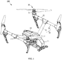
FIG. 1 is a schematic perspective view of an unmanned aerial vehicle according to embodiments of the present invention; -
FIG. 2 is a schematic perspective view of a rotor-wing assembly of an unmanned aerial vehicle according to embodiments of the present invention; -
FIG. 3 is a schematic cross-sectional view of the rotor-wing assembly of the unmanned aerial vehicle shown inFIG. 2 ; -
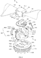
FIG. 4 is a schematic exploded view of the rotor-wing assembly of the unmanned aerial vehicle shown inFIG. 2 ; -
FIG. 5 is a schematic exploded view, from another perspective, of the rotor-wing assembly of the unmanned aerial vehicle shown inFIG. 2 ; and -
FIG. 6 is a schematic bottom view of the rotor-wing assembly of the unmanned aerial vehicle shown inFIG. 2 . - Description of symbols of main components:
- unmanned
aerial vehicle 100; -
fuselage 10, housing shell 11; -
arm 20,main arm 21,branch arm 22; - rotor-
wing assembly 30; -
motor 31, rotatingportion 312,central axis 31 a of motor, first position-limitingstructure 3121, position-limitinggroove 3121, guide-rail groove 3122,end surface 3123, position-limitinghole 3124, heat-dissipatinghole 3125; -
propeller 32,rotation axis 32a of propeller, hub, 321,connection hole 3211, mountinghole 3212,first alignment mark 3213,peripheral wall 3214,blade 322,first locking block 323,first mating surface 3231; -
connection assembly 33, lockingmember 331, mountingportion 3311, guidingportion 3312, guidingsection 33121, holdingsection 33122; - locking
catch 3313,second locking block 33131,second mating surface 33132,top surface 33133,first side surface 33134,second side surface 33135,recess 33136, engaginghole 33137,second alignment mark 33138; - reinforcing
member 332,first end 332,second end 3324, second position-limitingstructure 3321, position-limitingblock 3321, engaginghook 3322, engagingportion 33221,contact portion 33222,connection arm 3323; -
connection member 333,connection plate 3331, position-limitingshaft 3332, reinforcingblock 3333, position-limitingpost 3334. - The embodiments of the present invention will be described in detail below. The examples of the embodiments are illustrated in the accompanying drawings, in which the same or similar reference numerals are used to refer to the same or similar elements or elements having the same or similar functions. The embodiments described below by reference to the accompanying drawings are exemplary and intended to provide explanation of the present invention, which cannot be construed as the limitation of the present invention.
- In the description of the present invention, it should be understood that the terms "first" and "second" are used for descriptive purposes only, which cannot be construed as indicating or implying a relative importance, or implicitly specifying the number of the indicated technical features. Thus, the features defined with "first" and "second" may explicitly or implicitly include one or more features. In the description of the present invention, "a plurality of' means two or more than two, unless specifically stated otherwise.
- In the description of the present invention, it should be noted that unless specifically stated and limited, the terms "mounting," "joining," "connection" should be understood in a broad sense, such as, a fixed connection, a detachable connection, or an integral connection; a mechanical connection, an electrical connection, or a communicative connection; a direct connection, an indirect connection through an intermediate medium, an internal connection of two elements, or an interaction of two elements. For those ordinary skilled in the art, the specific meanings of the foregoing terms in the present invention can be understood on a case-by-case basis.
- The following disclosure provides many different embodiments or examples for implementing different structures of the present invention. For simplifying the present invention, the components and arrangements of the specific examples are described below. Certainly, they are merely examples and are not intended to limit the invention. In addition, the present invention may repeat the reference numerals and/or letters, which is for the purpose of simplicity and clarity and does not itself indicate the relationship between the various embodiments and/or settings discussed. Moreover, the present invention provides examples of various specific processes and materials, however, those ordinary skilled in the art can realize the use of other processes and/or the use of other materials.
- Referring to
FIG. 1 , the unmanned aerial vehicle (UAV) 100 of the present invention is a rotor-wing UAV. TheUAV 100 can fly and hover in the air to perform specific tasks, such as flight, tracking, monitoring, exploration, search and rescue, sowing, spraying pesticides, firefighting, and aerial photography. TheUAV 100 may be equipped with modules having predetermined functions, such as a sensor, a photographing device, a medical kit, to implement specific functions. - The
UAV 100 of the present invention includes afuselage 10, one ormore arms 20 and rotor-wing assemblies 30. The one ormore arms 20 are installed on thefuselage 10. The one or more rotor-wing assemblies 30 are installed on the one ormore arms 20 and arranged around thefuselage 10. In one embodiment, theUAV 100 may be a quad-rotor type UAV, and correspondingly the number of the rotor-wing assemblies 30 may be four. The four rotor-wing assemblies 30 may be centrally symmetrical about the vertical central axis of thefuselage 10 for balancing theUAV 100 during flight. - It can be understood that in other embodiments, the number of the rotor-
wing assemblies 30 may be set as other numbers according to actual needs. For example, the number of the one or more rotor-wing assemblies 30 may be one, two, three, six, eight, etc. - The
fuselage 10 may serve as a carrier of theUAV 100. Components, such as sensors, circuit boards, processors, communication modules, and batteries, may be carried outside and/or inside thefuselage 10. In one embodiment, thefuselage 10 includes a housing shell 11. A housing space of accommodating the foregoing components may be formed inside of the housing shell 11. The housing shell 11 may be streamlined, which can reduce air resistance during flight. In other embodiments, the housing shell 11 may have another shape, such as a polygonal shape, a circular shape, an elliptical shape. It can be understood that the housing shell 11 may also be omitted and thefuselage 10 may be formed only by overlapping brackets. - The
arm 20 may support and allow the rotor-wing assembly 30 to surround thefuselage 10 in a predetermined pattern. In one embodiment, the number of thearms 20 is two. Eacharm 20 supports two rotor-wing assemblies 30 and includes amain arm 21 and abranch arm 22. One end of themain arm 21 is connected to thefuselage 10, and the other end is connected to thebranch arm 22. Themain arm 21 and thebranch arm 22 are connected to each other in a T shape. The two rotor-wing assemblies 30 corresponding to eacharm 20 are arranged at two ends of thecorresponding branch arm 22, respectively. - In other embodiments, the number of the
arms 20 may be identical with the number of the rotor-wing assemblies 30, i.e., eacharm 20 may support one rotor-wing assembly 30. In these embodiments, thearm 22 can be omitted and the rotor-wing assembly 30 may be directly arranged at the end of themain arm 21. - Referring also to
FIG. 2 andFIG. 3 , the rotor-wing assembly 30 of the present invention includes amotor 31, apropeller 32, and aconnection assembly 33. Theconnection assembly 33 connects thepropeller 32 to themotor 31. - In one embodiment, the
motor 31 may be any type of suitable motor, such as a brushless motor or a brush motor. It can be understood that acentral axis 31a of themotor 31 coincides with arotation axis 32a of thepropeller 32. - Referring to
FIG. 4 , themotor 31 includes arotating portion 312. The rotatingportion 312 may have a cylindrical structure. The rotatingportion 312 includes anend surface 3123 opposing thepropeller 32 and asidewall 3126 connected to theend surface 3123. - The
end surface 3123 is formed with one or more first position-limitingstructures 3121, one or more guide-rail grooves 3122 extending in the circumferential direction of the propeller disk formed by the rotation of thepropeller 32, and one or more position-limitingholes 3124. The first position-limitingstructure 3121 may be a position-limitinggroove 3121. The position-limitinggroove 3121 may extend in the circumferential direction of the propeller disk formed by the rotation of thepropeller 32. The guide-rail groove 3122 is connected with the position-limitinggroove 3121. There may be two guide-rail grooves 3122 spaced apart and there may also be two position-limitinggrooves 3121. Each guide-rail groove 3122 may be connected with a position-limitinggroove 3121. The two guide-rail grooves 3122 may be centrosymmetrically distributed about thecentral axis 31a of therotating portion 312, and the two position-limitinggrooves 3121 may also be centrosymmetrically distributed about thecentral axis 31a of therotating portion 312. The position-limitinghole 3124, the guide-rail groove 3124, and the position-limitinggroove 3121 may all be arranged separately. In one embodiment, the number of the position-limitingholes 3124 may be two. The two position-limitingholes 3124 may be arranged centrosymmetrically about thecentral axis 31a of themotor 31. In other words, the two position-limitingholes 3124 may be arranged centrosymmetrically about therotation axis 32a of thepropeller 32. In other embodiments, the number of the one or more position-limitingholes 3124 may be one, three, four, etc. When there are a plurality of position-limitingholes 3124, the plurality of position-limitingholes 3124 may be arranged centrosymmetrically about thecentral axis 31a of themotor 31. In one embodiment, the two position-limitingholes 3124 may each be of a circular shape. In other embodiments, the two position-limitingholes 3124 may have one or more non-circular shapes including a polygonal shape, an oval shape or an elliptical shape, etc. It can be understood that in other embodiments, when the number of the position-limitingholes 3124 is more than two, one of the position-limitingholes 3124 may also have a non-circular shape, such as a polygonal shape, an oval shape, or an elliptical shape. - A plurality of heat-dissipating
holes 3125 may be formed on thesidewall 3126 of therotating portion 312, thereby dissipating heat generated by themotor 31 to reduce the temperature of themotor 31 and prolonging the lifetime of themotor 31. To further ensure the effect of heat dissipation and reinforce the strength of therotating portion 312, the rotatingportion 312 may be made of a metal material, such as aluminum alloy. - The
propeller 32 includes ahub 321, one ormore blades 322, and afirst locking block 323. - Referring to
FIG. 5 , thehub 321 may approximately be of a cylindrical shape. Aconnection hole 3211 and one or more mountingholes 3212 are formed at a side of thehub 321 facing the rotatingportion 312. Theconnection hole 3211 is arranged at the center of thehub 321, and theconnection hole 3211 may have an oblong shape. In other embodiments, theconnection hole 3211 may also be in another shape, such as a square shape or an elliptical shape. The one or more mountingholes 3212 are arranged around theconnection hole 3211. - Referring again to
FIG. 4 , afirst alignment mark 3213 is formed on the upper surface of thehub 321. In one embodiment, thefirst alignment mark 3213 may be of a triangle shape. It can be understood that thefirst alignment mark 3213 may be of another shape. For example, thefirst alignment mark 3213 may be in the shape of a circle, a square, an ellipse, etc. - The one or
more blades 322 are arranged on aperipheral wall 3214 of thehub 321. The number of theblades 322 may be two. The twoblades 322 are fixed to both sides of thehub 321 in the same radial direction of thehub 321. Theblades 322 can rotate to provide power for theUAV 100 to ascend and/or move forward. - The
first locking block 323 is arranged on theperipheral wall 3214. Thefirst locking block 323 is located between the twoblades 322. Aspace 3232 is formed between thefirst locking block 323 and one of theblades 322. - A
first mating surface 3231 is formed on a side of thefirst locking block 323 facing away from the rotatingportion 312. Thefirst mating surface 3231 is an inclined surface, tilted at a certain angle with respect to therotation axis 32a of thepropeller 32. In the direction of therotation axis 32a, the side of thefirst mating surface 3231 near therotation axis 32a is closer to themotor 31 than the side of thefirst mating surface 3231 away from therotation axis 32a. - The
connection assembly 33 includes a lockingmember 331, a reinforcingmember 332, and aconnection member 333. The lockingmember 331 may lock thepropeller 32 on therotating portion 312. The reinforcingmember 312 may reinforce the lockingmember 331 for locking thepropeller 32 to therotating portion 312. - The locking
member 331 includes a mountingportion 3311, a guidingportion 3312, and alocking catch 3313. The mountingportion 3311 is mounted on therotating portion 312, and the guidingportion 3312 extends from the mountingportion 3311 in the direction away from thepropeller 32. The lockingcatch 3313 extends from the mountingportion 3311 toward thepropeller 32. - The mounting
portion 3311 may approximately be of an annular shape. Preferably, the center of the mountingportion 3311 may coincide with therotation axis 32a of thepropeller 32, thus allowing the lockingmember 331 to rotate well around therotation axis 32a of thepropeller 32. - The guiding
portion 3312 is coupled with the guide-rail groove 3122 for guiding the lockingmember 331 to rotate about therotation axis 32a of thepropeller 32. Specifically, the guidingportion 3312 includes aguiding section 33121 connected with the mountingportion 3311 and aholding section 33122 connected with the guidingsection 33121. The guidingsection 33121 is located in the guide-rail groove 3122. The holdingsection 33122 is engaged with therotating portion 312 to prevent the lockingmember 331 from being separated from the rotatingportion 312. The guidingsection 33121 is connected with the holdingsection 33122 to form a certain angle, such that the holdingsection 33122 can be retained on therotating portion 312. The angel formed by the guidingsection 33121 and theholding section 33122 connecting with each other may be an acute angle or a right angle. There may be two guidingsections 33121. Each of the guidingsections 33121 may be coupled with a corresponding guide-rail groove 3122, respectively, thus allowing the lockingmember 331 to be stressed uniformly and rotate well around therotation axis 32a of thepropeller 32. - The locking
catch 3313 is coupled with thefirst locking block 323. When thepropeller 32 is locked, the lockingcatch 3313 may be connected with thefirst locking block 323, and asecond end 3324 of the reinforcingmember 332 may be engaged with the lockingcatch 3313. During installation, the lockingcatch 3313 may pass through thespace 3232 formed between thefirst locking block 323 and one of theblades 322. - A
second locking block 33131 is formed at the end of the lockingcatch 3313 that is connected with thefirst locking block 323. Thesecond locking block 33131 is coupled with thefirst locking block 323. The lockingmember 331 is engaged with thefirst locking block 323 through thesecond locking block 33131 to lock thepropeller 32. - A
second mating surface 33132 is formed on the side of thesecond locking block 33131 that faces the rotatingportion 312. Thesecond mating surface 33132 is an inclined surface tilted at a certain angle with respect to therotation axis 32a of thepropeller 32. In the direction of therotation axis 32a, the side of thesecond mating surface 33132 near therotation axis 32a is closer to themotor 31 than the side of thesecond mating surface 33132 away from therotation axis 32a. - Therefore, it can be understood that the two mutually coupled surfaces (the
first mating surface 3231 and the second mating surface 33132) of thefirst locking block 323 and thesecond locking block 33131 are both inclined surfaces tilted at a predetermined angle with respect to therotation axis 32a of thepropeller 32. In the direction of therotation axis 32a, the side of the surface near therotation axis 32a is closer to themotor 31 than the side away from therotation axis 32a. Preferably, the two mutually coupled surfaces of thefirst locking block 323 and thesecond locking block 33131 may be engaged with each other in an interference-fit manner. - The
second locking block 33131 also includes atop surface 33133, afirst side surface 33134, and asecond side surface 33135. Thefirst side surface 33133 is connected with thetop surface 33133. Thefirst side surface 33134 is close to and faces theperipheral wall 3214 of thepropeller 32. Thesecond side surface 33135 is opposite to thefirst side surface 33134. Arecess 33136 is provided on thetop surface 33133. Anengaging hole 33137 is provided on the bottom of therecess 33136. - The
top surface 33133 of thesecond locking block 33131 is formed with asecond alignment mark 33138. When thepropeller 32 is locked, thesecond alignment mark 33138 may be aligned with thefirst alignment mark 3213. In one embodiment, the first alignment may be of a triangle shape. It can be understood that thefirst alignment mark 3213 may also be another shape. For example, thefirst alignment mark 3213 may be in the shape of a circle, a square, an ellipse, etc. - The locking
member 331 may be in an integrally formed structure. For example, the lockingmember 331 may be formed by an injection-molding process or a die-casting process. - A
first end 3323 of the reinforcingmember 332 is mounted on therotating portion 312. Asecond end 3324 of the reinforcingmember 332 opposite to thefirst end 3323 may engage with the lockingmember 331 for reinforcing the lockingmember 331 to lock thepropeller 32 to therotating portion 312. - The
first end 3323 of the reinforcingmember 332 is formed with a second position-limitingstructure 3321. The second position-limitingstructure 3321 is a position-limitingblock 3321 capable of engaging with the position-limitinggroove 3121. - When the second position-limiting
structure 3321 is in a first position, thepropeller 32 may be in the locked state. The first position-limitingstructure 3121 may be coupled with the second position-limitingstructure 3321 to fix thefirst end 3323 of the reinforcingmember 332 on therotating portion 312. - When the second position-limiting
structure 3321 is located at a second position, the lockingmember 331 may be in the unlocked state, and the lockingmember 331 can rotate relative to thepropeller 32 about therotation axis 32a of thepropeller 32. - When the first position-limiting
structure 3121 is the position-limitinggroove 3121, and the second position-limitingstructure 3321 is the position-limitingblock 3321 capable of engaging with the position-limitinggroove 3121, the guide-rail groove 3122 may connect with the position-limitinggroove 3121, and the position-limitingblock 3321 can move from the position-limitinggroove 3121 into the position-limitinggroove 3121, such that the lockingmember 331 can rotate relative to thepropeller 32 about therotation axis 32a. - The
second end 3324 of the reinforcingmember 332 is formed with anengaging hook 3322. The engaginghook 3322 includes an engagingportion 33221 and acontact portion 33222 that are connected to each other at an angle to each other. The engagingportion 33221 is engaged in the engaginghole 33137, and thecontact portion 33222 is in contact with the bottom of therecess 33136. - The reinforcing
member 332 also includes aconnection arm 3323 connecting the second position-limitingstructure 3321 and theengaging hook 3322. Theconnection arm 3323 may be made of an elastic material, which may be a metal sheet such as a copper sheet, an iron sheet, or a 301 stainless-steel sheet. Theconnection 3323 may be elastically deformed, such that the position-limitingblock 3321 can be engaged in the position-limitinggroove 3121, or can be detached from the position-limitinggroove 3121 to dispose in the guide-rail groove 3122. - The reinforcing
member 332 may be integrally formed from a metal sheet, such that the reinforcingmember 332 can have a better elasticity. The reinforcingmember 332 may be made of a metal, such as copper, iron, or 301 stainless steel. The reinforcingmember 332 may be formed, for example, by a stamping process. There may be two reinforcingmembers 332, and each reinforcingmember 332 may be connected to alocking catch 3313. - The
connection member 333 is connected with thepropeller 32 and therotating portion 312. Theconnection member 333 is detachably mounted on the lockingmember 331. Theconnection member 333 includes aconnection plate 3331 and a position-limitingshaft 3332 extending from theconnection plate 3331 toward thepropeller 32. Theconnection plate 3331 holds against the lockingmember 331. The position-limitingshaft 3332 is connected to thepropeller 32 and can restrict the rotation of thepropeller 32 relative to theconnection member 333. - The position-limiting
shaft 3332 matches the shape of theconnection hole 3211. In one embodiment, the position-limitingshaft 3332 may have an oblong shape. In other embodiments, theconnection hole 3211 may also be in the shape of a square, an ellipse, etc. The position-limitingshaft 3332 extends into theconnection hole 3211 to restrict the rotation of thepropeller 32 with respect to theconnection member 333. - The
connection member 333 also includes a reinforcingblock 3333 and a position-limitingpost 3334. The reinforcingblock 3333 extends from theconnection plate 3331 toward thehub 321, and corresponds to the mountinghole 3212 arranged on the side of thehub 321 facing the rotatingportion 312. The reinforcingblock 3333 is mounted in the mountinghole 3212. - The position-limiting
post 3334 extends from theconnection plate 3331 to therotating portion 312. The position-limitingpost 3334 is connected to therotating portion 312 by passing through the lockingmember 331, which may restrict the rotation of theconnection member 333 relative to therotating portion 312, such that therotating portion 312 can drive and rotate thepropeller 32 through theconnection member 333. - The position-limiting
post 3334 is engaged in the position-limitinghole 3124, thus allowing the connecting relationship between theconnection member 333 and therotating portion 312 to be simple. In one embodiment, the position-limitingpost 3334 may have a circular shape. In other embodiments, the position-limitingpost 3334 may also be in another shape, such as a polygonal shape, an oblong shape, or an elliptical shape. There may be at least two position-limitingposts 3334. The position-limitinghole 3124 may correspond to the position-limitingpost 3334. At least two position-limitingposts 3334 may be disposed in the corresponding position-limitingholes 3124. - The position-limiting post(s) 3334 corresponding to the position-limiting hole(s) 3124 means that the number and shape of the position-limiting post(s) 3334 are identical or approximately identical, and in terms of position, the position-limiting post(s) 3334 can be inserted into the position-limiting hole(s) 3124.
- Referring to
FIG. 2 ,FIG. 3 ,FIG. 4 , andFIG. 6 , during the assembly of the rotor-wing assembly 30, the engaginghook 3322 may be first engaged into the engaginghole 33137 for mounting the reinforcingmember 332 on the lockingmember 331. Subsequently, the lockingmember 331 with the reinforcingmember 332 may be mounted on therotating portion 312 through the coupling between the guidingportion 3312 and the guide-rail groove 3122. Afterwards, the position-limitingpost 3334 of theconnection member 333 may be inserted into the position-limitinghole 3124 of therotating portion 312, thus allowing theconnection member 333 to be mounted on the lockingmember 331. Lastly, the lockingcatch 3313 may pass through thespace 3232 formed between thefirst locking block 323 of thepropeller 32 and one of theblades 322, and theconnection hole 3211 and the mountinghole 3212 of thepropeller 32 may be aligned and engaged with the position-limitingshaft 3332 and the reinforcingblock 3333 of theconnection member 333, respectively, such that thepropeller 32 can be mounted on theconnection member 333. At this point, thepropeller 32 may be in the unlocked state and can be rotated together with therotating portion 312. The position-limitingblock 3321 may be located in the guide-rail groove 3122. The lockingmember 331 and the reinforcingmember 332 can be rotated together with thepropeller 32. Thefirst alignment mark 3213 of thepropeller 32 may be not aligned with thesecond alignment mark 33138 of the lockingmember 331. - When the
propeller 32 needs to switch from the unlocked state to the locked state, the lockingmember 331 and the reinforcingmember 332 may rotate together with respect to therotation axis 32a of thepropeller 32. Thefirst mating surface 3231 may attach to thesecond mating surface 33132. With the rotation of the lockingmember 331 and the reinforcingmember 332, the position-limitingblock 3321 may eject from the guide-rail groove 3122 into the guide-rail grove 3122 and the lockingmember 331 cannot rotate relative to thepropeller 32. At this point, thefirst alignment mark 3213 may align with thesecond alignment mark 33138, and the locking of thepropeller 32 is completed. - When the
propeller 32 needs to switch from the locked state to the unlocked state, the reinforcingmember 332 may be pressed inwardly by hand, thus moving the position-limitingblock 3321 into the guide-rail groove 3122 and away from the position-limitinggroove 3121. Then the lockingmember 331 may be rotated and thepropeller 32 can be switched from the locked state to the unlocked state. - In the rotor-
wing assembly 30 and theUAV 100 implemented by the present invention, the reinforcingmember 332 may reinforce the lockingmember 331 to lock thepropeller 32 on therotating portion 312, which can prevent the lockingmember 331 from being separated from thepropeller 32 and causing thepropeller 32 to fly off themotor 31 of theUAV 100, thus ensuring the normal flight of theUAV 100. - Moreover, the
first liming structure 3121 may be a position-limiting block. The second position-limitingstructure 3321 may be a position-limiting groove capable of engaging with the position-limitingblock 3321, thus allowing the connecting structure between the reinforcingmember 332 and therotating portion 312 to be simpler and the cost of the rotor-wing assembly 30 to be reduced. - In addition, the guide-
rail groove 3122 may be connected with the position-limitinggroove 3121, such that the position-limitingblock 3321 can be engaged with or disengaged from the position-limitinggroove 3121. - Further, the engaging
hook 3322 may be coupled with the engaginghole 3313, thus allowing the connection between the reinforcingmember 332 and the lockingmember 331 to be simple, and inhibiting the rotation of the lockingmember 331 relative to thepropeller 32. Thecontact portion 33222 may be in contact with the bottom of therecess 33136, which allows the reinforcingmember 332 and the lockingmember 331 to be connected more tightly. Theconnection arm 3323 may be made of an elastic material, such that the reinforcingmember 332 can be elastic in nature. - In some embodiments, the first position-limiting
structure 3121 may be a position-limiting groove. Correspondingly, the second position-limitingstructure 3321 may be a position-limiting block capable of engaging with the position-limiting groove. - In some embodiments, the engaging
hook 3322 may include an engaging surface engaged with thetop surface 33133. The reinforcingmember 332 can be directly engaged with thetop surface 33133 via the engaging surface to prevent theengaging hook 3322 from falling off the lockingmember 331. - In some embodiments, the engaging
hook 3322 may include two engaging surfaces connected with each other at an angle to each other. The two engaging surfaces may be engaged with thetop surface 33133 and thefirst side surface 33134, respectively. - In some embodiments, the
top surface 33133 may be provided with an engaging hole. The engaginghook 3322 may include an engaging portion and a contact portion connected with each other at an angle to each other. The engaging portion may be engaged in the engaging hole. The contact portion may be in contact with thetop surface 33133. - In some embodiments, the
second side surface 33135 may be provided with an engaging hole. The engaginghook 3322 may be engaged into the engaging hole. - In the description of the present specification, reference to the terms "one embodiment," "some embodiments," "an exemplary embodiment," "an example," "a specific example," or "some examples" means that a description of the detailed embodiment or exemplary-embodiments-described feature, structure, material, or characteristic is included in at least one embodiment or example of the present invention In the present specification, a schematic representation of the foregoing terms does not necessarily refer to the same embodiment or example. Furthermore, the particular features, structures, materials, or characteristics described may be combined in any suitable manner in one or more embodiments or examples.
- Moreover, the terms "first" and "second" are used for descriptive purpose only and are not to be construed as indicating or implying a relative importance or implicitly specifying the number of the indicated technical features. Thus, features defined with "first" and "second" may explicitly or implicitly include at least one feature. In the description of the present invention, "a plurality of' means at least two (e.g., two, three), unless specifically stated otherwise.
- Although the principles and the specific embodiments of the present invention have been described above, with the instructions of the present invention, those skilled in the art can make various modifications and changes on the basis of the described embodiments, all of which fall within the scope of protection of the present invention. It should be understood by those skilled in the art that the foregoing description of the present invention is only to provide explanation of the present invention, not to limit the present invention. The scope of protection of the present invention is defined by the claims and their equivalents.
Claims (23)
- A rotor-wing assembly, comprising a motor, a propeller, and a connection assembly connecting the propeller to the motor, the motor including a rotating portion, characterized in that:
the connection assembly comprises a locking member and a reinforcing member disposed between the propeller and the motor, the locking member locks the propeller on the rotating portion; a first end of the reinforcing member is mounted on the rotating portion, a second end of the reinforcing member opposite to the first end engages with the locking member for reinforcing the locking member to lock the propeller on the rotating portion. - The rotor-wing assembly according to claim 1, characterized in that, the rotating portion is formed with a first position-limiting structure, the first end of the reinforcing member is formed with a second position-limiting structure, when the second position-limiting structure is in a first position, the propeller is in a locked state, the first position-limiting structure is coupled with the second position-limiting structure to fix the first end of the reinforcing member on the rotating portion;
when the second position-limiting structure is in a second position, the propeller is in an unlocked state, and the locking member can rotate relative to the propeller about a rotation axis of the propeller. - The rotor-wing assembly according to claim 2, characterized in that, the first position-limiting structure is a position-limiting block, the second position-limiting structure is a position-limiting groove capable of engaging with the position-limiting block; and/or
the first position-limiting structure is a position-limiting groove, the second position-limiting structure is a position-limiting block capable of engaging with the position-limiting groove. - The rotor-wing assembly according to claim 3, characterized in that, the position-limiting groove extends in a circumferential direction of a propeller disk formed by rotation of the propeller.
- The rotor-wing assembly according to claim 2, characterized in that, the rotating portion is formed with a guide-rail groove extending in a circumferential direction of a propeller disk formed by rotation of the propeller, the locking member comprises a mounting portion mounted on the rotating portion and a guiding portion extending from the mounting portion in a direction away from the propeller, the guiding portion is coupled with the guide-rail groove for guiding the locking member to rotate about the rotation axis.
- The rotor-wing assembly according to claim 5, characterized in that, the guiding portion comprises a guiding section connected with the mounting portion and a holding section connected with the guiding section, the guiding section is in the guide-rail groove, the holding section engages on the rotating portion to prevent the locking member from being separated from the rotating portion.
- The rotor-wing assembly according to claim 5, wherein when the first position-limiting structure is a position-limiting groove and the second position-limiting structure is a position-limiting block capable of engaging with the position-limiting groove, the guide-rail groove is connected with the position-limiting groove, the position-limiting block can move from the position-limiting groove into the position-limiting groove, such that the locking member can rotate relative to the propeller about the rotation axis.
- The rotor-wing assembly according to claim 5, characterized in that, the locking member further comprises a locking catch extending from the mounting portion to the propeller;
the propeller includes a hub, a blade arranged on a peripheral wall of the hub, and a first locking block arranged on the peripheral wall and coupled with the locking catch, when the propeller is locked, the locking catch is connected with the first locking block, the second end of the reinforcing member engages with the locking catch. - The rotor-wing assembly according to claim 8, characterized in that, one end of the locking catch connecting with the first locking block is formed with a second locking block coupled to the first locking block, the locking member is engaged with the first locking block to lock the propeller through the second locking block.
- The rotor-wing assembly according to claim 9, characterized in that, two mutually coupled surfaces of the first locking block and the second locking block are both inclined surfaces tilted at a predetermined angle relative to the rotation axis of the propeller, in a direction of the rotation axis, sides of the surfaces near the rotation axis are closer to the motor than sides away from the rotation axis.
- The rotor-wing assembly according to claim 10, characterized in that, the two mutually coupled surfaces of the first locking block and the second locking block are engaged with each other in an interference fit manner.
- The rotor-wing assembly according to any of claims 8-11, characterized in that, the second locking block comprises a top surface, a first side surface connected to the top surface adjacent to and facing the peripheral wall, and a second side surface opposite to the first side surface, the second end of the reinforcing member is formed with an engaging hook,
the engaging hook comprises an engaging surface, the engaging surface engaging on the top surface; or
the engaging hook comprises two engaging surfaces connected with each other at an angle to each other, the two engaging surfaces engaging on the top surface and the first side surface, respectively; or
the top surface is provided with an engaging hole, the engaging hook comprises an engaging portion and a contact portion connected with each other at an angle to each other, the engaging portion is engaged in the engaging hole, the contact portion is in contact with the top surface; or
the top surface is provided with a recess, a bottom of the recess is provided with the engaging hole, the engaging hook comprises the engaging portion and the contact portion connected with each other at an angle to each other, the engaging portion is engaged in the engaging hole, the contact portion is in contact with the bottom of the recess; or
the second side surface is provided with the engaging hole, and the engaging hook is engaged in the engaging hole. - The rotor-wing assembly according to claim 12, characterized in that, the reinforcing member further comprises a connection arm connecting the second position-limiting structure and the engaging hook, the connection arm is made of an elastic material.
- The rotor-wing assembly according to claim 8, wherein there are two blades, the first locking block is located between the two blades, a space is formed between the first locking block and one of the two blades for allowing the locking catch to pass through.
- The rotor-wing assembly according to claim 8, characterized in that, the connection assembly further comprises a connection member connecting the propeller and the rotating portion, the connection member can be detachably mounted on the locking member.
- The rotor-wing assembly according to claim 15, characterized in that, the connection member comprises a connection plate and a position-limiting shaft extending from the connecting plate to the propeller, the connection plate holds against the locking member, the position-limiting shaft is connected with the propeller and can restrict the rotation of the propeller relative to the connection member.
- The rotor-wing assembly according to claim 16, characterized in that, the connection member further comprises a reinforcing block extending from the connection plate to the hub, a side of the hub facing the rotating portion is provided with a mounting hole corresponding to the reinforcing block, and the reinforcing block is mounted in the mounting hole.
- The rotor-wing assembly according to claim 16, characterized in that, the connection member further comprises a position-limiting post extending from the connection plate to the rotating portion, the position-limiting post passes through the locking member and is connected to the rotating portion, and can restrict the rotation of the connection member relative to the rotating portion.
- The rotor-wing assembly according to claim 18, characterized in that, the rotating portion comprises an end surface facing the connection member, the end surface is provided with a position-limiting hole, the position-limiting post is engaged in the position-limiting hole.
- The rotor-wing assembly according to claim 19, characterized in that, the position-limiting post is of a polygonal shape, an oblong shape, or an elliptical shape.
- The rotor-wing assembly according to claim 19, characterized in that, there are at least two position-limiting posts, the position-limiting posts correspond to the position-limiting holes, the at least two position-limiting posts are located in the corresponding position-limiting holes.
- The rotor-wing assembly according to claim 21, characterized in that, the at least two position-limiting holes are arranged centrosymmetrically about the rotation axis.
- An unmanned aerial vehicle, characterized in comprising the rotor-wing assembly according to any of claims 1-22.
Applications Claiming Priority (1)
| Application Number | Priority Date | Filing Date | Title |
|---|---|---|---|
| PCT/CN2016/105769 WO2018086128A1 (en) | 2016-11-14 | 2016-11-14 | Rotor assembly and unmanned aerial vehicle |
Publications (2)
| Publication Number | Publication Date |
|---|---|
| EP3473542A1 true EP3473542A1 (en) | 2019-04-24 |
| EP3473542A4 EP3473542A4 (en) | 2019-11-13 |
Family
ID=58849599
Family Applications (1)
| Application Number | Title | Priority Date | Filing Date |
|---|---|---|---|
| EP16921046.5A Withdrawn EP3473542A4 (en) | 2016-11-14 | 2016-11-14 | ROTOR ASSEMBLY AND AERIAL VEHICLE WITHOUT PILOT |
Country Status (4)
| Country | Link |
|---|---|
| US (1) | US11524775B2 (en) |
| EP (1) | EP3473542A4 (en) |
| CN (2) | CN111319761B (en) |
| WO (1) | WO2018086128A1 (en) |
Cited By (1)
| Publication number | Priority date | Publication date | Assignee | Title |
|---|---|---|---|---|
| US10569860B2 (en) * | 2016-12-28 | 2020-02-25 | Haoxiang Electric Energy (Kunshan) Co., Ltd. | Detachable propeller holder device |
Families Citing this family (29)
| Publication number | Priority date | Publication date | Assignee | Title |
|---|---|---|---|---|
| EP3476730B1 (en) * | 2016-10-28 | 2021-04-28 | SZ DJI Technology Co., Ltd. | Engine/propeller connection assembly |
| CN106347653B (en) | 2016-11-18 | 2019-12-10 | 深圳市道通智能航空技术有限公司 | power device, screw and aircraft |
| KR102345523B1 (en) * | 2017-08-03 | 2021-12-30 | 삼성전자주식회사 | Propulsion system comprising detachable propellar and unmanned aerial vehicle comprising the same |
| CN107585290B (en) * | 2017-08-18 | 2019-09-27 | 广州极飞科技有限公司 | Blade fixed structure and UAV |
| TWI642859B (en) * | 2017-11-20 | 2018-12-01 | 光寶電子(廣州)有限公司 | Assembling-disassembling structure and unmanned aircraft |
| CN109808882A (en) * | 2017-11-20 | 2019-05-28 | 光宝电子(广州)有限公司 | Disassembly and assembly structure and unmanned plane |
| CN109969389A (en) * | 2017-12-28 | 2019-07-05 | 昆山优尼电能运动科技有限公司 | A blade connection structure |
| WO2019140658A1 (en) * | 2018-01-19 | 2019-07-25 | 深圳市大疆创新科技有限公司 | Heat dissipation structure, heat dissipation method and device, unmanned aerial vehicle and readable storage medium |
| US10780975B2 (en) * | 2018-04-27 | 2020-09-22 | Wing Aviation Llc | Clip-on propeller mount |
| CN110662695A (en) * | 2018-05-04 | 2020-01-07 | 深圳市大疆创新科技有限公司 | Propeller mounting structure, propeller, power suit and unmanned aerial vehicle |
| CN110480286A (en) * | 2019-07-04 | 2019-11-22 | 安徽松羽工程技术设备有限公司 | A kind of new type propeller production method and new type propeller |
| WO2021003609A1 (en) * | 2019-07-05 | 2021-01-14 | 深圳市大疆创新科技有限公司 | Power assembly and unmanned aerial vehicle |
| USD1056763S1 (en) * | 2019-11-05 | 2025-01-07 | Zero Zero Robotics Inc. | Unmanned aerial vehicle |
| CN112996721A (en) * | 2019-12-31 | 2021-06-18 | 深圳市大疆创新科技有限公司 | Screw, driving system and unmanned vehicles |
| US12441491B2 (en) | 2020-04-17 | 2025-10-14 | Sonin Hybrid, LLC | Powertrain for aerial vehicle |
| CN111591420B (en) * | 2020-05-14 | 2026-04-28 | 珠海市和裕丰船舶设备有限公司 | Adjustable pitch propeller adjustment assembly and propeller pitch adjustment method |
| CN111568292B (en) * | 2020-06-12 | 2025-06-13 | 江苏美的清洁电器股份有限公司 | Dust suction device and vacuum cleaner having the same |
| US12269577B2 (en) | 2020-06-25 | 2025-04-08 | Sony Group Corporation | Propeller attaching device and propeller attaching method |
| USD1045668S1 (en) * | 2020-08-24 | 2024-10-08 | Sonin Hybrid, LLC | Drone |
| US11820493B2 (en) | 2020-08-24 | 2023-11-21 | Sonin Hybrid, LLC | Landing support assembly for aerial vehicles |
| CN112357072A (en) * | 2020-11-06 | 2021-02-12 | 武汉鸟瞰天下科技有限公司 | Multi-rotor unmanned aerial vehicle |
| CN112407300A (en) * | 2020-12-01 | 2021-02-26 | 广东历鼎龙动力科技有限公司 | Brushless motor used for plant protection unmanned aerial vehicle |
| CN113104206B (en) * | 2021-05-27 | 2022-07-26 | 厦门致睿智控地信科技有限公司 | Multi-rotor aircraft propeller quick mounting mechanism |
| CN215098210U (en) * | 2021-05-31 | 2021-12-10 | 上海峰飞航空科技有限公司 | Arm and unmanned aerial vehicle |
| CN113859575A (en) * | 2021-09-15 | 2021-12-31 | 中国空气动力研究与发展中心空天技术研究所 | A composite wing/rotor unmanned aerial vehicle propeller safety locking device and locking method |
| CN113942632B (en) * | 2021-11-01 | 2025-03-25 | 南昌三瑞智能科技股份有限公司 | Propeller clamp mechanism capable of reducing vibration of folding propeller and aircraft |
| CN114347738B (en) * | 2022-01-12 | 2023-06-02 | 广东汇天航空航天科技有限公司 | Arm mechanism and flight device |
| CN115123536A (en) * | 2022-08-08 | 2022-09-30 | 广东蚂蚁工场制造有限公司 | Locking structure of unmanned aerial vehicle screw |
| TW202438390A (en) * | 2023-01-13 | 2024-10-01 | 美商艾羅維羅門特股份有限公司 | Vtol propeller adapter and method |
Family Cites Families (18)
| Publication number | Priority date | Publication date | Assignee | Title |
|---|---|---|---|---|
| DE10020839A1 (en) * | 2000-04-28 | 2001-10-31 | Christian Ramoser | Propeller for model aircraft has guide plate fixed to engine drive shaft |
| CN201572529U (en) * | 2009-09-24 | 2010-09-08 | 上海九鹰电子科技有限公司 | An electric power model aircraft propeller connector |
| CN202966659U (en) * | 2012-12-03 | 2013-06-05 | 佛山市安尔康姆航拍科技有限公司 | Unmanned aerial vehicle rotor wing rapid mounting and dismounting structure |
| CN103921937B (en) * | 2013-01-11 | 2016-08-24 | 佛山市安尔康姆航空科技有限公司 | The quick fixation structure of unmanned vehicle rotor and unmanned vehicle |
| CA2904575C (en) * | 2013-03-14 | 2022-02-01 | Aeryon Labs Inc. | Folding propellers system |
| CN203306224U (en) * | 2013-05-31 | 2013-11-27 | 深圳市大疆创新科技有限公司 | Propeller and aircraft provided with same |
| CN105517892B (en) * | 2014-11-04 | 2018-06-12 | 深圳市大疆创新科技有限公司 | Locking mechanism has the propeller and aircraft of locking mechanism |
| CN204279920U (en) * | 2014-11-04 | 2015-04-22 | 深圳市大疆创新科技有限公司 | Lockout mechanism, has screw propeller and the aircraft of lockout mechanism |
| WO2016070334A1 (en) * | 2014-11-04 | 2016-05-12 | 深圳市大疆创新科技有限公司 | Locking mechanism, propeller and aircraft both having same |
| WO2016074133A1 (en) * | 2014-11-10 | 2016-05-19 | 深圳市大疆创新科技有限公司 | Driving device, propeller and power system |
| CN204433073U (en) * | 2015-01-21 | 2015-07-01 | 深圳市大疆创新科技有限公司 | Flight equipment |
| CN205113705U (en) * | 2015-07-23 | 2016-03-30 | 广州飞米电子科技有限公司 | Power device and aircraft |
| CN105173072B (en) * | 2015-07-23 | 2018-01-23 | 广州飞米电子科技有限公司 | Power set and aircraft |
| CN204956919U (en) * | 2015-08-18 | 2016-01-13 | 王军 | Screw connection structure and unmanned aerial vehicle |
| CN205168894U (en) * | 2015-09-25 | 2016-04-20 | 深圳市大疆创新科技有限公司 | Rotor subassembly and have unmanned vehicles of rotor subassembly |
| CN105366041B (en) * | 2015-11-30 | 2019-02-12 | 易瓦特科技股份公司 | More rotor structures applied to unmanned plane |
| CN205469777U (en) * | 2016-01-11 | 2016-08-17 | 优利科技有限公司 | aircraft |
| CN105799916B (en) * | 2016-06-05 | 2017-10-03 | 吴敏 | Inter-embedding type opens oar seat soon |
-
2016
- 2016-11-14 EP EP16921046.5A patent/EP3473542A4/en not_active Withdrawn
- 2016-11-14 CN CN202010192644.0A patent/CN111319761B/en not_active Expired - Fee Related
- 2016-11-14 WO PCT/CN2016/105769 patent/WO2018086128A1/en not_active Ceased
- 2016-11-14 CN CN201680002423.4A patent/CN106687370B/en not_active Expired - Fee Related
-
2019
- 2019-05-02 US US16/401,930 patent/US11524775B2/en active Active
Cited By (1)
| Publication number | Priority date | Publication date | Assignee | Title |
|---|---|---|---|---|
| US10569860B2 (en) * | 2016-12-28 | 2020-02-25 | Haoxiang Electric Energy (Kunshan) Co., Ltd. | Detachable propeller holder device |
Also Published As
| Publication number | Publication date |
|---|---|
| WO2018086128A1 (en) | 2018-05-17 |
| CN106687370A (en) | 2017-05-17 |
| CN111319761A (en) | 2020-06-23 |
| CN111319761B (en) | 2022-05-27 |
| US11524775B2 (en) | 2022-12-13 |
| EP3473542A4 (en) | 2019-11-13 |
| US20190256204A1 (en) | 2019-08-22 |
| CN106687370B (en) | 2020-05-22 |
Similar Documents
| Publication | Publication Date | Title |
|---|---|---|
| US11524775B2 (en) | Rotor-wing assembly and unmanned aerial vehicle | |
| JP6553291B2 (en) | Unmanned aerial vehicle having a rotary wing assembly and a rotary wing assembly | |
| EP3213995B1 (en) | Motor heat dissipation structure for a rotorcraft | |
| US20210013777A1 (en) | System, kit, and method for dissipating heat generated by a motor assembly | |
| CN109661762B (en) | Motors, power units, power suits and aircraft | |
| US12009724B2 (en) | Motor and rotor blade apparatus | |
| US20190181701A1 (en) | Motor for drone and drone comprising same | |
| US12149127B2 (en) | Rotor for electric motor | |
| WO2020107407A1 (en) | Motor mount, motor assembly, arm assembly, and unmanned aerial vehicle | |
| CN205168894U (en) | Rotor subassembly and have unmanned vehicles of rotor subassembly | |
| CN216509050U (en) | Paddle, screw, power module and unmanned vehicles | |
| CN209209022U (en) | Motor mount, electric machine assembly, horn component and unmanned plane | |
| WO2020113386A1 (en) | Electronic speed controller, power device, and unmanned aerial vehicle | |
| WO2020103253A1 (en) | Protective shell, power device and unmanned aerial vehicle | |
| CN110972473A (en) | A kind of protective shell, power device and unmanned aerial vehicle | |
| CN113678059A (en) | PTZ camera and its casing, movable platform | |
| KR20220146067A (en) | Rotor Assembly and Apparatus for Driving Propeller Using the Same | |
| CN223261340U (en) | Magnetic ring structure and motor | |
| CN116710358A (en) | Propellers, power units, power systems and unmanned aerial vehicles | |
| CN214045345U (en) | Resolver installation structure and motor | |
| CN217036846U (en) | Inner rotor motor | |
| US12620841B2 (en) | Stator having bus bar structure, propeller driving motor using same, and method for manufacturing stator | |
| CN209112424U (en) | Spliced UAV fuselage and UAV with the same | |
| CN213473507U (en) | Multi-rotor unmanned aerial vehicle | |
| CN209217835U (en) | A kind of low-speed high-torque motor |
Legal Events
| Date | Code | Title | Description |
|---|---|---|---|
| STAA | Information on the status of an ep patent application or granted ep patent |
Free format text: STATUS: THE INTERNATIONAL PUBLICATION HAS BEEN MADE |
|
| PUAI | Public reference made under article 153(3) epc to a published international application that has entered the european phase |
Free format text: ORIGINAL CODE: 0009012 |
|
| STAA | Information on the status of an ep patent application or granted ep patent |
Free format text: STATUS: REQUEST FOR EXAMINATION WAS MADE |
|
| 17P | Request for examination filed |
Effective date: 20190103 |
|
| AK | Designated contracting states |
Kind code of ref document: A1 Designated state(s): AL AT BE BG CH CY CZ DE DK EE ES FI FR GB GR HR HU IE IS IT LI LT LU LV MC MK MT NL NO PL PT RO RS SE SI SK SM TR |
|
| AX | Request for extension of the european patent |
Extension state: BA ME |
|
| RIN1 | Information on inventor provided before grant (corrected) |
Inventor name: PENG, TAO Inventor name: GUO, XIAOKAI Inventor name: OU, DI Inventor name: SUN, LIANG |
|
| A4 | Supplementary search report drawn up and despatched |
Effective date: 20191011 |
|
| RIC1 | Information provided on ipc code assigned before grant |
Ipc: B64D 35/00 20060101ALI20191007BHEP Ipc: B64C 27/32 20060101AFI20191007BHEP |
|
| DAV | Request for validation of the european patent (deleted) | ||
| DAX | Request for extension of the european patent (deleted) | ||
| STAA | Information on the status of an ep patent application or granted ep patent |
Free format text: STATUS: EXAMINATION IS IN PROGRESS |
|
| 17Q | First examination report despatched |
Effective date: 20200924 |
|
| GRAP | Despatch of communication of intention to grant a patent |
Free format text: ORIGINAL CODE: EPIDOSNIGR1 |
|
| STAA | Information on the status of an ep patent application or granted ep patent |
Free format text: STATUS: GRANT OF PATENT IS INTENDED |
|
| RIC1 | Information provided on ipc code assigned before grant |
Ipc: B64C 39/02 20060101AFI20220309BHEP |
|
| INTG | Intention to grant announced |
Effective date: 20220404 |
|
| STAA | Information on the status of an ep patent application or granted ep patent |
Free format text: STATUS: THE APPLICATION IS DEEMED TO BE WITHDRAWN |
|
| 18D | Application deemed to be withdrawn |
Effective date: 20220817 |