EP3473539A1 - An aircraft assembly including a wingtip device - Google Patents
An aircraft assembly including a wingtip device Download PDFInfo
- Publication number
- EP3473539A1 EP3473539A1 EP18196230.9A EP18196230A EP3473539A1 EP 3473539 A1 EP3473539 A1 EP 3473539A1 EP 18196230 A EP18196230 A EP 18196230A EP 3473539 A1 EP3473539 A1 EP 3473539A1
- Authority
- EP
- European Patent Office
- Prior art keywords
- wing tip
- spigot
- wing
- connector
- tip device
- Prior art date
- Legal status (The legal status is an assumption and is not a legal conclusion. Google has not performed a legal analysis and makes no representation as to the accuracy of the status listed.)
- Granted
Links
Images



Classifications
-
- B—PERFORMING OPERATIONS; TRANSPORTING
- B64—AIRCRAFT; AVIATION; COSMONAUTICS
- B64C—AEROPLANES; HELICOPTERS
- B64C3/00—Wings
- B64C3/18—Spars; Ribs; Stringers
- B64C3/187—Ribs
-
- B—PERFORMING OPERATIONS; TRANSPORTING
- B64—AIRCRAFT; AVIATION; COSMONAUTICS
- B64C—AEROPLANES; HELICOPTERS
- B64C5/00—Stabilising surfaces
- B64C5/08—Stabilising surfaces mounted on, or supported by, wings
-
- B—PERFORMING OPERATIONS; TRANSPORTING
- B64—AIRCRAFT; AVIATION; COSMONAUTICS
- B64C—AEROPLANES; HELICOPTERS
- B64C3/00—Wings
- B64C3/10—Shape of wings
-
- B—PERFORMING OPERATIONS; TRANSPORTING
- B64—AIRCRAFT; AVIATION; COSMONAUTICS
- B64C—AEROPLANES; HELICOPTERS
- B64C23/00—Influencing air flow over aircraft surfaces, not otherwise provided for
- B64C23/06—Influencing air flow over aircraft surfaces, not otherwise provided for by generating vortices
- B64C23/065—Influencing air flow over aircraft surfaces, not otherwise provided for by generating vortices at the wing tips
- B64C23/069—Influencing air flow over aircraft surfaces, not otherwise provided for by generating vortices at the wing tips using one or more wing tip airfoil devices, e.g. winglets, splines, wing tip fences or raked wingtips
-
- B—PERFORMING OPERATIONS; TRANSPORTING
- B64—AIRCRAFT; AVIATION; COSMONAUTICS
- B64C—AEROPLANES; HELICOPTERS
- B64C3/00—Wings
- B64C3/10—Shape of wings
- B64C3/14—Aerofoil profile
-
- B—PERFORMING OPERATIONS; TRANSPORTING
- B64—AIRCRAFT; AVIATION; COSMONAUTICS
- B64C—AEROPLANES; HELICOPTERS
- B64C3/00—Wings
- B64C3/18—Spars; Ribs; Stringers
-
- B—PERFORMING OPERATIONS; TRANSPORTING
- B64—AIRCRAFT; AVIATION; COSMONAUTICS
- B64C—AEROPLANES; HELICOPTERS
- B64C3/00—Wings
- B64C3/18—Spars; Ribs; Stringers
- B64C3/185—Spars
-
- B—PERFORMING OPERATIONS; TRANSPORTING
- B64—AIRCRAFT; AVIATION; COSMONAUTICS
- B64C—AEROPLANES; HELICOPTERS
- B64C3/00—Wings
- B64C3/26—Construction, shape, or attachment of separate skins, e.g. panels
-
- B—PERFORMING OPERATIONS; TRANSPORTING
- B64—AIRCRAFT; AVIATION; COSMONAUTICS
- B64C—AEROPLANES; HELICOPTERS
- B64C3/00—Wings
- B64C3/58—Wings provided with fences or spoilers
-
- B—PERFORMING OPERATIONS; TRANSPORTING
- B64—AIRCRAFT; AVIATION; COSMONAUTICS
- B64F—GROUND OR AIRCRAFT-CARRIER-DECK INSTALLATIONS SPECIALLY ADAPTED FOR USE IN CONNECTION WITH AIRCRAFT; DESIGNING, MANUFACTURING, ASSEMBLING, CLEANING, MAINTAINING OR REPAIRING AIRCRAFT, NOT OTHERWISE PROVIDED FOR; HANDLING, TRANSPORTING, TESTING OR INSPECTING AIRCRAFT COMPONENTS, NOT OTHERWISE PROVIDED FOR
- B64F5/00—Designing, manufacturing, assembling, cleaning, maintaining or repairing aircraft, not otherwise provided for; Handling, transporting, testing or inspecting aircraft components, not otherwise provided for
- B64F5/10—Manufacturing or assembling aircraft, e.g. jigs therefor
-
- B—PERFORMING OPERATIONS; TRANSPORTING
- B64—AIRCRAFT; AVIATION; COSMONAUTICS
- B64C—AEROPLANES; HELICOPTERS
- B64C3/00—Wings
- B64C3/10—Shape of wings
- B64C3/14—Aerofoil profile
- B64C2003/146—Aerofoil profile comprising leading edges of particular shape
-
- B—PERFORMING OPERATIONS; TRANSPORTING
- B64—AIRCRAFT; AVIATION; COSMONAUTICS
- B64C—AEROPLANES; HELICOPTERS
- B64C3/00—Wings
- B64C3/10—Shape of wings
- B64C3/14—Aerofoil profile
- B64C2003/147—Aerofoil profile comprising trailing edges of particular shape
-
- Y—GENERAL TAGGING OF NEW TECHNOLOGICAL DEVELOPMENTS; GENERAL TAGGING OF CROSS-SECTIONAL TECHNOLOGIES SPANNING OVER SEVERAL SECTIONS OF THE IPC; TECHNICAL SUBJECTS COVERED BY FORMER USPC CROSS-REFERENCE ART COLLECTIONS [XRACs] AND DIGESTS
- Y02—TECHNOLOGIES OR APPLICATIONS FOR MITIGATION OR ADAPTATION AGAINST CLIMATE CHANGE
- Y02T—CLIMATE CHANGE MITIGATION TECHNOLOGIES RELATED TO TRANSPORTATION
- Y02T50/00—Aeronautics or air transport
- Y02T50/10—Drag reduction
Definitions
- the present invention relates to an aircraft assembly.
- the present invention relates to an aircraft assembly comprising a wing tip device connected to a wing tip of a wing.
- the present invention also relates to a wing tip device, and in particular a winglet, and a method of assembling a method of assembling a wing tip device with a wing tip of a wing.
- Wing tip devices are known to be disposed at the wing tips of aircraft wings. Devices such as winglets, raked wing tips and fences are collectively known as aerodynamic wing tip devices. Such devices are used to reduce the effects of lift induced drag.
- Lift induced drag is caused by the generation of vortices at the wing tip. Such drag is mitigated by an increase in wing span. Increases in wing span in the plane of the wing are not always possible due to space requirements at, e.g. airports. As such out-of-plane extensions to the wing are commonly used to increase the effective wing span without increasing the geometric span of the aircraft. These take the form of aerodynamic wing tip devices.
- a wing tip device is typically attached to the wing tip of a wing by means of connectors which connect the wing spars and the wing tip device spars.
- a series of splice plates or butt straps may be used which span the upper and lower skins of the wing tip device and the wing at the point at which they join.
- the butt straps transfer load through the wing skin, which is primarily designed to absorb the bending load across the wing span, and less well suited to absorb local, concentrated, loads. Further, many joining locations on the wing skin are required to spread the applied load. Although this has the desired effect of reducing the load per joining location, it creates a statically indeterminate system making the loads at each point difficult to predict. Therefore each joint is typically over-engineered adding weight and cost to the aircraft.
- a still further problem is that the interface between the parts is quite sensitive to differences in geometry caused by tolerance build-up at the interface. As such, any mismatch between the two components needs to be addressed upon assembly. This increases the cost of assembly and makes it more difficult to replace the wing tip devices in service. As such the ease of interchangeability of wing tip devices is reduced.
- temperature effects and loading in use can cause differential expansion or contraction of the wing tip device and the wing tip, which can cause high stresses at the mounting points.
- a wing tip device connected to a wing tip of a wing by a first connector, a second connector and a third connector, the wing tip device comprising a front device spar and a rear device spar, wherein the first connector is associated with the rear device spar, the second connector is spaced apart, in a chordwise direction, forward of the first connector, the third connector is spaced apart, in a chordwise direction, rearward of the first connector, and the third connector comprises a spigot mounting formation.
- the second connector may be associated with the front device spar.
- the first and second connectors act through the main load bearing members of the wing tip device.
- the wing tip may comprise a wing trailing edge
- the wing tip device may comprise a device trailing edge and the third connector may be configured to connect the device trailing edge with the wing trailing edge.
- this configuration helps to constrain movement of the trailing edge of the wing tip device relative to the wing tip. Flutter and relative deflection of the trailing edge of the wing tip device may be restricted by the rigid connection provided by the spigot mounting formation.
- the wing tip device may comprise a closing rib located aft of the rear device spar, wherein the spigot mounting formation may be associated with the closing rib.
- the spigot mounting formation may be on the closing rib. With such an arrangement, it is possible to limit the forces acting through the upper and lower covers of the skins of the wing.
- the wing tip may comprise a forward wing spar and a rearward wing spar, wherein the first connector may associated with the rearward wing spar.
- the second connector may be associated with the forward wing spar.
- the wing tip may comprise a trailing edge end rib located aft of rearward wing spar and the spigot mounting formation may be associated with the trailing edge end rib.
- the spigot mounting formation may be on the trailing edge end rib.
- the spigot mounting formation may comprise a spigot associated with the wing tip device or the wing tip, and a spigot retainer associated with the other of the wing tip device or the wing tip for receiving the spigot in a male/female connection.
- the spigot may be on the wing tip device and the spigot retainer may be on the wing tip. This helps ease of assembly.
- the spigot retainer may comprise a bush.
- the bush may comprise a wear plate.
- the spigot retainer may comprise an elongate retainer slot extending in the chordwise direction.
- a height of the retainer slot may be configured to substantially conform with a diameter of the spigot in a direction perpendicular to the chordwise direction. With this arrangement, it is possible to move towards a statically determinate load path, and to allow for thermal expansion.
- some adjacent components to the spigot mounting formation may be formed from a composite material and others from a metallic material. Such materials may have different rates of thermal expansion, and such variances may be accounted for.
- the wing tip device is predominantly formed of composite materials, and the wing tip is predominantly formed from metallic materials.
- the spigot may be slidable in the slot between a first condition in which the trailing edge of the wing tip device is out of alignment with the wing tip trailing edge and a second condition in which the which the trailing edge of the wing tip device moves into alignment with the wing tip trailing edge.
- the trailing edge of the wing tip device may be movable in response to aerodynamic forces acting on the wing tip device during flight. When the aerodynamic forces absent from the wing tip device, the spigot may be slidable in the slot to reduce static forces acting on the wing tip device.
- the first connector may comprise a first spigot mounting formation
- the second connector may comprise a second spigot mounting formation, wherein the spigot mounting formation as set out above may be a third spigot mounting formation.
- the first spigot mounting formation may comprise a first spigot associated with the wing tip device or the wing tip, and a first spigot retainer associated with the other of the wing tip device or the wing tip;
- the second spigot mounting formation may comprise a second spigot associated with the wing tip device or the wing tip, and a second spigot retainer associated with the other of the wing tip device or the wing tip; and wherein the spigot and spigot retainer as set out above may be a third spigot and a third spigot retainer.
- Each connector may be configurable between an engaged condition in which the respective spigot is received by the respective spigot retainer in a male/female connection, and a disengaged condition in which the respective spigot is withdrawn from the respective spigot retainer.
- the first connector When the wing tip device is brought into engagement with the wing tip, the first connector may be configured to move into its engaged condition prior to the second connector moving into its engaged condition.
- the second connector When the wing tip device is brought into engagement with the wing tip, the second connector may be configured to move into its engaged condition prior to the third connector moving into its engaged condition.
- each connector is aligned and engaged individually. Furthermore, the arrangement ensures that the connectors on the main load bearing members are engaged first.
- the third spigot may upstand from a plane extending in a chordwise direction, and wherein the length of the third spigot from the plane to a third spigot free end may be less than the length of the first spigot from the plane to a first spigot free end.
- the length of the second spigot from the plane to a second spigot free end may be greater than the length of the third spigot from the plane to the third spigot free end.
- the first spigot retainer may comprise a first retainer hole and wherein the dimensions of the first retainer hole may be configured to substantially conform with a diameter of the spigot in both directions parallel to and perpendicular to the chordwise direction.
- the second spigot retainer may comprise an elongate second retainer slot extending in a chordwise direction, and wherein the height of the second retainer slot may be configured to conform with a diameter of the spigot in a direction perpendicular to the chordwise direction.
- the wing tip and the wing tip device When assembled, the wing tip and the wing tip device may together define a spanwise axis, wherein an elongate axis of the or each spigot is at an offset angle to the spanwise axis at the juncture of the wing tip and the wing tip device and, optionally, wherein the offset angle is 2 to 6 degrees and, optionally, wherein the offset angle is 4 degrees.
- each of the spigots may extend upwardly from the wing tip device.
- the wing tip may comprise a wing skin
- the wing tip device may comprise a wing tip device skin
- the aircraft assembly may comprise a butt-strap between the wing skin and the wing tip device skin.
- the wing skin may be a metallic material, and the wing tip device skin may be a composite material.
- the butt strap Prior to assembly of the wing tip and the wing tip device, the butt strap may be a first butt-strap formed from a metallic material on the wing tip device skin, and the wing tip device may be a second butt-strap formed from a composite material on the wing skin. This arrangement aids assembly by providing components of the same material with each other for fixing when the wing tip and wing tip assembly are brought together.
- the or each butt-strap may be disposed only at or forward of the first connector. As such, the assembly time of the wing tip device with the wing tip is reduced. Loading is carried through the spigot mounting formation and so loading on the wing skin and wing tip device skin is reduced.
- the wing tip device may be a winglet.
- a wing tip device configured to connect to a wing tip of an aircraft wing, the wing tip device comprising a front device spar, a rear device spar, a first load-bearing wing tip connecting spigot associated with the rear device spar, a second load-bearing wing tip connecting spigot spaced apart in a chordwise direction forward of the first spigot, and a third wing tip connecting spigot spaced apart in a chordwise direction rearward of the first spigot.
- the second spigot may be associated with the front device spar.
- the wing tip device may comprise a wing tip device trailing edge, wherein the third spigot may be associated with the wing tip device trailing edge.
- a method of assembling a wing tip device and a wing tip of a wing comprising locating the wing tip device relative to the wing tip, engaging a first spigot associated with the rear device spar and one of the wing tip device or the wing tip with a first spigot retainer associated with the other of the wing tip device or the wing tip, subsequently, engaging a second spigot spaced apart, in a chordwise direction, forward of the first spigot and associated with one of the wing tip device or the wing tip with a second spigot retainer associated with the other of the wing tip device or the wing tip, and subsequently, engaging a third spigot spaced apart, in a chordwise direction, rearward of the first spigot and associated with one of the wing tip device or the wing tip with a third spigot retainer associated with the other of the wing tip device or the wing tip.
- a wing tip device configured to connect to a wing tip of an aircraft wing, the wing tip device comprising a first load-bearing wing tip connecting spigot, a second load-bearing wing tip connecting spigot spaced apart in a chordwise direction forward of the first spigot, and a third wing tip connecting spigot spaced apart in a chordwise direction rearward of the first spigot.
- the aircraft 10 includes a fuselage 11.
- Two wings 12 extend from the fuselage 11. It will be appreciated that the fuselage 11 and wings 12 may take a variety of different planned formed shapes and profiles depending on the particular application.
- Each wing 12 has a wing root 13 at the juncture with the fuselage 11.
- the wing 12 has a wing tip 20 at a distal end to the wing root 13.
- the wing 12 has a leading edge 15 and a trailing edge 16.
- the wing 12 comprises a wing box 17.
- the wing box forms the main body of the wing 12.
- front refers to components towards the leading edge of the wing
- rear refers to components towards the trailing edge of the wing.
- forward and rearward shall be construed accordingly.
- the position of features may be construed relative to other components, for example a forward component may be disposed on a forward side of another component, but towards the rear of the wing.
- the trailing edge relates to a rearmost section aft of the rear spar.
- the wing tip 20 is formed by the end of the wing 12.
- a wing tip device 30 is at the wing tip 20.
- the wing tip device 30 is a winglet.
- the wing tip 20 terminates at an outboard end 18.
- the wing tip device 30 extends from the wing tip 20.
- the wing tip device 30 extends from the outboard end 18.
- the wing 12 has a spanwise axis which extends in a direction from the wing root 13 to the wing tip 20.
- the wing tip device 30 extends in a spanwise direction from the wing tip 20.
- the wing 12 has a chordwise axis which extends in a direction from the leading edge 15 to the trailing edge 16.
- the wing 12 and wing tip device 30 each experience an aerodynamic lift force which acts through the centre of pressure.
- the wing tip device 30 is attached to the wing tip 20 at the outboard end 18.
- the wing tip 30 is shown in Figures 3 and 7 .
- a mounting arrangement 40 (as shown in Figures 1 to 8B ) mounts the wing tip device 30 to the wing tip 20. Aerodynamic forces act on the wing tip device 30, and so the wing tip device 30 is stably attached to the outboard end 18 by the mounting arrangement 40.
- a torque may act on the wing tip device 30 to urge rotation of the wing tip device 30 about an axis extending in a spanwise direction.
- a torque may act on the wing tip device 30 to urge rotation of the wing tip device 30 about an axis extending in a chordwise direction.
- a wing assembly 19 is shown in schematic form comprising the wing tip 20 and the wing tip device 30.
- the wing tip 20 comprises a forward wing spar 21 and a rearward wing spar 22.
- Each of the forward and rearward spars 21, 22 run in a generally spanwise direction.
- the forward and rearward wing spars 21, 22 converge along the span of the wing towards the wing tip 20.
- a series of ribs are positioned along the wing span and extend in the direction of the wing chord.
- the wing tip 20 is covered by a wing skin 24 comprising a wing upper cover 24a and a wing lower cover 24b.
- the spars and ribs are covered by the wing skin primarily designed to present an aerodynamic surface to the airflow.
- the wing tip 20 terminates at the outboard end 18.
- the wing tip 20 has an end rib 26.
- the end rib 26 extends between the forward and rearward wing spars 21, 22.
- the end rib 26 is at the outboard end 18.
- the end rib 26 is exposed when the wing tip device 30 is removed from the wing tip 20.
- the wing tip 20 has a trailing edge end rib 27.
- the trailing edge end rib 27 is disposed rearward of the rearward wing spar 22.
- the trailing edge end rib 27 extends from the rearward wing spar 22.
- the trailing edge end rib 27 is at the outboard end 18. The trailing edge end rib 27 is exposed when the wing tip device 30 is removed from the wing tip 20.
- the wing tip device 30, in this embodiment the winglet, comprises a wing tip device root 31 and a free end 32 distanced from and vertically spaced from the wing tip device root 31.
- the wing tip device 30 comprises a front device spar 33 and a rear device spar 34.
- the front device spar 33 extends from a position partway between the free end 32 and the device root 31 and extends to the device root 31.
- the front device spar 33 is disposed towards a device leading edge 35.
- the rear device spar 34 runs from the position midway along the wing tip device 30 towards the device root 31.
- the rear device spar 34 diverges from the front device spar 33 towards the device root 31.
- the rear device spar 34 is disposed substantially midway along the device root 31 at the device root 31 in the chordwise direction.
- the rear device spar 34 is disposed rearwardly of the front device spar 33 towards a device trailing edge 36.
- a wing tip device skin 39 covers the wing tip device 30 in order to present an aerodynamic surface to the airflow.
- the wing tip device skin 39 has an upper device cover 39a and a lower device cover 39b.
- the wing tip device 30 has a root rib 37.
- the root rib 37 extends between the front and rear device spars 33, 34.
- the root rib 37 is at the device root 31.
- the root rib 37 is exposed when the wing tip device 30 is removed from the wing tip 20.
- the wing tip device 30 has a closing rib 38.
- the closing rib 38 is disposed rearward of the rear device spar 34.
- the closing rib 38 extends from the rear device spar 34.
- the closing rib 38 is at the device root 31. The closing rib 38 is exposed when the wing tip device 30 is removed from the wing tip 20.
- the mounting arrangement 40 comprises a first connector 41, a second connector 42 and a third connector 43.
- the mounting arrangement 40 comprises a first, upper, butt-strap 44 and a second, lower, butt-strap 45.
- the wing tip and the wing tip device together define a spanwise axis 46.
- the wing tip device 30 attaches to the wing tip 20 at three primary attachment points A, B and C.
- the front device spar 33 attaches to the forward wing spar 21 via first connector 41 at attachment point A.
- the rear device spar 34 attaches to the rearward wing spar 22 via second connector 42 at attachment point B.
- the wing tip device trailing edge 36 attaches to the wing trailing edge 16 via third connector 43 at attachment point C.
- the first, second and third connectors 41, 42, 43 are at the device root 31.
- the first connector 41 comprises as a spigot mounting formation including a first spigot 50.
- the first spigot 50 protrudes from the device root 31.
- the first spigot 50 includes an elongate pin 51.
- the first spigot 50 is on the rear device spar 34.
- a first spigot fitting 52 mounts the first spigot 50 to a root end 34a of the rear device spar 34.
- the first spigot fitting 52 is associated with the rear device spar 34. Loading through the rear device spar 34 is able to act through the first spigot 50.
- the first spigot 50 extends in a spanwise direction from the root end 34a.
- the first spigot 50 has a first spigot free end 53.
- the first spigot free end 53 is at a distal end of the first spigot 50 to the first spigot fitting 52.
- the first spigot 50 defines a first elongate axis from the first spigot fitting 52 to the first spigot free end 53.
- the first connector 41 comprises a first spigot retainer 54.
- the first spigot retainer 54 is configured to receive the first spigot 50.
- the first spigot retainer 54 is on the wing tip 20.
- the first spigot retainer 54 is at the outboard end 18.
- the first spigot retainer 54 is on the rearward wing spar 22.
- the first spigot retainer 54 is associated with the rearward wing spar 22. Loading through the rearward wing spar 22 is able to act through the first spigot retainer 54.
- the first spigot retainer 54 comprises a bush 55.
- the bush 55 is formed from bronze, although other suitable materials may be used.
- the bush 55 comprises a first retainer hole 56, as shown in Figures 8A and 8B .
- the bush 55 defines a loading surface.
- the first retainer hole 56 has dimensions which are configured to substantially conform with a diameter of the first spigot 50 in both directions parallel to and perpendicular to the chordwise direction.
- the first retainer hole 56 has a diameter to form a tight fit with the first spigot 50.
- the first connector 41 acts as a locking pin spigot in which the first connector 50 is able to react to side forces, and so all degrees of freedom are constrained. In particular, there is no ability to move in a spanwise or chordwise direction.
- the second connector 42 comprises as a spigot mounting formation including a second spigot 60.
- the second spigot 60 protrudes from the device root 31.
- the second spigot 60 includes an elongate pin 61.
- the second spigot 60 is on the front device spar 33.
- a second spigot fitting 62 mounts the second spigot 60 to a root end 33a of the front device spar 34.
- the second spigot fitting 62 is associated with the front device spar 33a. Loading through the front device spar 33a is able to act through the second spigot 60.
- the second spigot 60 extends in a spanwise direction from the root end 33a.
- the second spigot 60 has a second spigot free end 63.
- the second spigot free end 63 is at a distal end of the second spigot 60 to the second spigot fitting 62.
- the second spigot 60 defines a second elongate axis from the second spigot fitting 62 to the second spigot free end 63.
- the second connector 42 comprises a second spigot retainer 64.
- the second spigot retainer 64 is configured to receive the second spigot 60.
- the second spigot retainer 64 is on the wing tip 20.
- the second spigot retainer 64 is at the outboard end 18.
- the second spigot retainer 64 is on the forward wing spar 21.
- the second spigot retainer 64 is associated with the forward wing spar 21. Loading through the forward wing spar 21 is able to act through the second spigot retainer 64.
- the second spigot retainer 64 comprises a bush 65.
- the bush 65 is formed from bronze, although other suitable materials may be used.
- the bush 65 comprises a second retainer slot 66, as shown in Figures 8A and 8B .
- the bush 65 defines a loading surface.
- the second retainer slot 66 is elongate and extends in a chordwise direction.
- the height of the second retainer slot 66 is configured to substantially conform with the diameter of the second spigot 60 in a direction perpendicular to the chordwise direction.
- the length of the second retainer slot 66 is greater than the diameter of the second spigot 60. As such, the second connector is unable to react a side force in the chordwise direction within certain limits.
- the third connector 43 comprises a third spigot 70.
- the third spigot 70 protrudes from the device root 31.
- the third spigot 70 includes an elongate pin 71.
- the third spigot 70 is on the closing rib 38.
- a third spigot fitting 72 mounts the third spigot 70 to an inboard face 38a of the closing rib 38.
- the third spigot fitting 72 is associated with the closing rib 38. Loading on the device trailing edge 36 is able to act through the third spigot 70. Such loading may result from aerodynamic forces acting on the wing tip device 30.
- the third spigot 70 extends in a spanwise direction from the root end 33a.
- the third spigot 70 has a third spigot free end 73.
- the third spigot free end 73 is at a distal end of the third spigot 70 to the third spigot fitting 72.
- the third spigot 70 defines a third elongate axis from the third spigot fitting 72 to the third spigot free end 73.
- the third connector 43 comprises as a spigot mounting formation including a third spigot retainer 74.
- the third spigot retainer 74 is configured to receive the third spigot 70.
- the third spigot retainer 74 is on the wing tip 20.
- the third spigot retainer 74 is at the outboard end 18.
- the third spigot retainer 74 is on the trailing edge end rib 27.
- the third spigot retainer 74 is associated with the trailing edge end rib 27. Loading through the trailing edge end rib 27 is able to act through the second spigot retainer 64.
- the third spigot retainer 74 mounts to an outboard face 27a of the trailing edge end rib 27. Loading on the wing trailing edge 16 is able to act through the third spigot retainer 74. Such loading may result from aerodynamic forces acting on the wing trailing edge 16.
- the third spigot retainer 74 comprises a bush 75.
- the bush 75 is formed from bronze, although other suitable materials may be used.
- the bush 75 comprises a third retainer slot 76, as shown in Figures 8A and 8B .
- the bush 75 is formed by a wear plate 77.
- An aperture is formed through the trailing edge end rib which aligns to the mounting of the third spigot retainer 74 to provide for the third spigot 70 to extend therethrough.
- the bush 75 defines a loading surface.
- the third spigot retainer slot 76 is elongate and extends in a chordwise direction.
- the height of the third retainer slot 76 is configured to substantially conform with the diameter of the third spigot 70 in a direction perpendicular to the chordwise direction.
- the length of the third retainer slot 76 is greater than the diameter of the third spigot 70. As such, the third connector 43 is unable to react a side force in the chordwise direction within certain limits.
- the loading acting through the third spigot 70 is configured to be lower than that acting through the first and second spigots 50, 60.
- the third connector 43 is configured to react loading through the wing trailing edge 16 and the device trailing edge 36. As such, the third connector 43 reacts forces acting on the wing tip 20 and wing tip device 30 aft of the rearward wing spar 22 and rear device spar 34.
- the third connector 43 acts to ensure that the wing skin 24 and wing tip device skin 39 are maintained in alignment.
- the wing trailing edge 16 and the device trailing edge 36 are not load bearing and conventionally may flutter during flight.
- the provision of the third connector 43 ensures that the device trailing edge 36 and the wing trailing edge 16 move together, minimising the creation of gaps between the surfaces of the wing tip device 30 and the wing tip 20 during flight. As such aerodynamic efficiency at the juncture of the wing tip 20 and wing tip device 30 is maximised.
- the third connector 43 acts through ribs at the wing tip and wing tip device and so forces acting through the skins are minimised.
- the upper and lower butt-straps 44, 45 of the mounting arrangement 40 extend between the wing tip 20 and wing tip device 30 when assembled.
- the upper butt strap 44 extends between the upper cover 24a of the wing skin 24 and the upper cover 39a of the device skin 39.
- the upper butt strap 44 is fixedly mounted between the upper cover 24a of the wing skin 24 and the upper cover 39a of the device skin 39 and acts as a splice plate.
- the lower butt strap 45 extends between the lower cover 24b of the wing skin 24 and the lower cover 39b of the device skin 39.
- the lower butt strap 45 is fixedly mounted between the lower cover 24b of the wing skin 24 and the lower cover 39b of the device skin 39 and acts as a splice plate.
- the wing skin 24 is a metallic skin and the wing tip device skin 39 is a composite skin.
- the upper butt strap 44 is a metallic butt-strap and is mounted to the composite wing tip device skin 39 prior to assembly of the wing tip 20 and wing tip device 30.
- the lower butt-strap 45 is a composite butt-strap and is mounted to the metallic wing skin 24 prior to assembly of the wing tip 20 and wing tip device 30.
- Each spigot 50, 51, 52 is at an angular offset from the spanwise axis 46 defined by the wing tip 20 and the wing tip device 30.
- the elongate axis of each spigot 50, 51, 52 is at an offset angle to the spanwise axis at the juncture of the outboard end 18 of the wing tip 20 and the device root 31 of the wing tip device 30.
- Each spigot 50, 51, 52 extends upwardly from the device root 31. That is, each spigot is inclined towards the plane of the upper cover 24a of the wing 12 away from the device root 31, when assembled.
- the offset angle is in the range of 2 to 6 degrees. In the present embodiment, the offset angle is 4 degrees. This arrangement allows the wing tip device 30 to be presented to the wing tip 20 from below during assembly.
- Each connector 41, 42, 43 is configurable between an engaged condition, when the wing tip 20 and wing tip device 30 are in an assembled condition, in which the respective spigot is received by the respective spigot retainer in a male/female connection, and a disengaged condition, when the wing tip 20 and wing tip device 30 are in an assembled condition, and in which the respective spigot is withdrawn from the respective spigot retainer.
- the first, second and third spigots 50, 60, 70 extend from the wing tip device 30 by differing extents.
- the third spigot 70 upstands from a plane extending in a chordwise direction of the wing tip device 30.
- the length of the third spigot 70 from the plane to the third spigot free end 73 is less than the length of the first spigot 70 from the plane to the first spigot free end 53.
- the length of the second spigot 60 from the plane to the second spigot free end 63 is greater than the length of the third spigot 70 from the plane to the third spigot free end 73.
- the first spigot 50 protrudes further outwardly than the second spigot 60.
- the second spigot 60 protrudes further outwardly than the third spigot 70.
- each attachment point can be designed around a known load case. This offers an advantage over the prior art in which generally a high number of fixings are used for load-bearing purposes and consequently a statically indeterminate system is formed in which the exact load case on each attachment point is unknown. Therefore each attachment point has to be over-engineered to cope with the worst possible case.
- the wing assembly 19 is shown comprising the wing tip 20 and a wing tip device 30.
- the wing tip device 30 is attached to the wing tip 20 at attachment points B, A, C in a chordwise direction from leading edge to trailing edge.
- the attachment points B, A and C have their horizontal chordwise axes (parallel to axis Y) of rotation aligned as will be described below.
- the wing tip device 30 is moved proximate the wing tip 20 on a trolley jack or similar.
- the jack is elevated to move the wing tip device 30 such that the first, second and third spigots 50, 60, 70 are aligned with their respective receiving points on the wing tip 20.
- the wing tip device 30 may be presented from slightly below the wing tip 20 due to the offset angular arrangement of the spigots 50, 60, 70. The joints can then be assembled.
- the first connector 41 is configured to initially move into its engaged condition prior to the second and third connectors 42, 43 moving into their engaged condition, as shown in Figure 9A .
- the wing tip device 20 is easily moved by rotation to align the second spigot 60 with the second spigot retainer 63.
- the wing tip device is then further moved in an axial direction so that the first and second spigots 50, 60 are engaged with their respective spigot retainers, as shown in Figure 9B .
- the load bearing requirements may be carried by the first and second connectors 41, 42 without a load being carried by the third connector 70 during assembly.
- Rotation of the wing tip device 30 about the wing tip 20 is prevented by the first and second connectors 41, 42.
- the wing tip device is then further moved in an axial direction so that the third spigot 70 is engaged with its respective spigot retainer 74, as shown in Figure 9C .
- the wing tip device 30 is then fully assembled with the wing tip 20.
- the butt-straps 44, 45 are fixed between the skins 24, 39.
- the jack can then be removed.
- each connector is aligned and engaged sequentially.
- the first connector When the wing tip device 30 is brought into engagement with the wing tip, the first connector may be configured to move into its engaged condition prior to the second connector moving into its engaged condition.
- the second connector When the wing tip device is brought into engagement with the wing tip, the second connector may be configured to move into its engaged condition prior to the third connector moving into its engaged condition.
- each connector is aligned and engaged sequentially. Furthermore, the arrangement ensures that the connectors on the main load bearing members are engaged first.
- the spigots are disposed on the wing tip device, and the spigot retainers are on the wing tip, it will be understood that the arrangement of one or more of the connectors may be reversed.
- one or more spigots may be on the wing tip.
- An advantage of the spigots being on the wing tip is that the ability of the aircraft to fly without one or more wing tip assemblies assembled on the aircraft is enhanced. Furthermore, ease of alignment of the spigot and spigot retainers, and therefore a reduction in assembly time, is enhanced by locating the spigots on the wing tip device.
Landscapes
- Engineering & Computer Science (AREA)
- Aviation & Aerospace Engineering (AREA)
- Mechanical Engineering (AREA)
- Manufacturing & Machinery (AREA)
- Transportation (AREA)
- Structures Of Non-Positive Displacement Pumps (AREA)
- Turbine Rotor Nozzle Sealing (AREA)
- Toys (AREA)
- Aerodynamic Tests, Hydrodynamic Tests, Wind Tunnels, And Water Tanks (AREA)
- Connection Of Plates (AREA)
- Details Of Connecting Devices For Male And Female Coupling (AREA)
- Retarders (AREA)
Abstract
Description
- The present invention relates to an aircraft assembly. In particular, the present invention relates to an aircraft assembly comprising a wing tip device connected to a wing tip of a wing. The present invention also relates to a wing tip device, and in particular a winglet, and a method of assembling a method of assembling a wing tip device with a wing tip of a wing.
- Wing tip devices are known to be disposed at the wing tips of aircraft wings. Devices such as winglets, raked wing tips and fences are collectively known as aerodynamic wing tip devices. Such devices are used to reduce the effects of lift induced drag.
- Lift induced drag is caused by the generation of vortices at the wing tip. Such drag is mitigated by an increase in wing span. Increases in wing span in the plane of the wing are not always possible due to space requirements at, e.g. airports. As such out-of-plane extensions to the wing are commonly used to increase the effective wing span without increasing the geometric span of the aircraft. These take the form of aerodynamic wing tip devices.
- A wing tip device is typically attached to the wing tip of a wing by means of connectors which connect the wing spars and the wing tip device spars. A series of splice plates or butt straps may be used which span the upper and lower skins of the wing tip device and the wing at the point at which they join.
- The butt straps transfer load through the wing skin, which is primarily designed to absorb the bending load across the wing span, and less well suited to absorb local, concentrated, loads. Further, many joining locations on the wing skin are required to spread the applied load. Although this has the desired effect of reducing the load per joining location, it creates a statically indeterminate system making the loads at each point difficult to predict. Therefore each joint is typically over-engineered adding weight and cost to the aircraft.
- A still further problem is that the interface between the parts is quite sensitive to differences in geometry caused by tolerance build-up at the interface. As such, any mismatch between the two components needs to be addressed upon assembly. This increases the cost of assembly and makes it more difficult to replace the wing tip devices in service. As such the ease of interchangeability of wing tip devices is reduced.
- Further, temperature effects and loading in use can cause differential expansion or contraction of the wing tip device and the wing tip, which can cause high stresses at the mounting points.
- According to an aspect of the invention, there is provided a wing tip device connected to a wing tip of a wing by a first connector, a second connector and a third connector, the wing tip device comprising a front device spar and a rear device spar, wherein the first connector is associated with the rear device spar, the second connector is spaced apart, in a chordwise direction, forward of the first connector, the third connector is spaced apart, in a chordwise direction, rearward of the first connector, and the third connector comprises a spigot mounting formation.
- With this arrangement movement of the wing tip device aft of the rear device spar is constrained. Rigidity of the wing tip device towards and at the trailing edge is aided.
- As such, relative flexing between the wing towards the trailing edge of the wing is restricted by a spigot mounting formation, and so rigidity in a thickness direction is aided.
- The second connector may be associated with the front device spar.
- With such an arrangement, the first and second connectors act through the main load bearing members of the wing tip device.
- The wing tip may comprise a wing trailing edge, and the wing tip device may comprise a device trailing edge and the third connector may be configured to connect the device trailing edge with the wing trailing edge.
- As such, this configuration helps to constrain movement of the trailing edge of the wing tip device relative to the wing tip. Flutter and relative deflection of the trailing edge of the wing tip device may be restricted by the rigid connection provided by the spigot mounting formation.
- The wing tip device may comprise a closing rib located aft of the rear device spar, wherein the spigot mounting formation may be associated with the closing rib.
- The spigot mounting formation may be on the closing rib. With such an arrangement, it is possible to limit the forces acting through the upper and lower covers of the skins of the wing.
- The wing tip may comprise a forward wing spar and a rearward wing spar, wherein the first connector may associated with the rearward wing spar. The second connector may be associated with the forward wing spar. As such, the first and second connectors act through the main load bearing members of the wing tip device.
- The wing tip may comprise a trailing edge end rib located aft of rearward wing spar and the spigot mounting formation may be associated with the trailing edge end rib. The spigot mounting formation may be on the trailing edge end rib.
- The spigot mounting formation may comprise a spigot associated with the wing tip device or the wing tip, and a spigot retainer associated with the other of the wing tip device or the wing tip for receiving the spigot in a male/female connection.
- The spigot may be on the wing tip device and the spigot retainer may be on the wing tip. This helps ease of assembly.
- The spigot retainer may comprise a bush.
- The bush may comprise a wear plate.
- The spigot retainer may comprise an elongate retainer slot extending in the chordwise direction.
- A height of the retainer slot may be configured to substantially conform with a diameter of the spigot in a direction perpendicular to the chordwise direction. With this arrangement, it is possible to move towards a statically determinate load path, and to allow for thermal expansion. In some embodiments, some adjacent components to the spigot mounting formation may be formed from a composite material and others from a metallic material. Such materials may have different rates of thermal expansion, and such variances may be accounted for. In embodiments, the wing tip device is predominantly formed of composite materials, and the wing tip is predominantly formed from metallic materials.
- The spigot may be slidable in the slot between a first condition in which the trailing edge of the wing tip device is out of alignment with the wing tip trailing edge and a second condition in which the which the trailing edge of the wing tip device moves into alignment with the wing tip trailing edge. The trailing edge of the wing tip device may be movable in response to aerodynamic forces acting on the wing tip device during flight. When the aerodynamic forces absent from the wing tip device, the spigot may be slidable in the slot to reduce static forces acting on the wing tip device.
- The first connector may comprise a first spigot mounting formation, and the second connector may comprise a second spigot mounting formation, wherein the spigot mounting formation as set out above may be a third spigot mounting formation.
- As such, the use of such connector configurations, aids assembly and also provides for a rigid coupling between the wing tip and wing tip device. Furthermore, ease of interchangeability of the wing tip device is enhanced.
- The first spigot mounting formation may comprise a first spigot associated with the wing tip device or the wing tip, and a first spigot retainer associated with the other of the wing tip device or the wing tip; the second spigot mounting formation may comprise a second spigot associated with the wing tip device or the wing tip, and a second spigot retainer associated with the other of the wing tip device or the wing tip; and wherein the spigot and spigot retainer as set out above may be a third spigot and a third spigot retainer.
- Each connector may be configurable between an engaged condition in which the respective spigot is received by the respective spigot retainer in a male/female connection, and a disengaged condition in which the respective spigot is withdrawn from the respective spigot retainer.
- When the wing tip device is brought into engagement with the wing tip, the first connector may be configured to move into its engaged condition prior to the second connector moving into its engaged condition.
- When the wing tip device is brought into engagement with the wing tip, the second connector may be configured to move into its engaged condition prior to the third connector moving into its engaged condition.
- This arrangement simplifies assembly of the wing tip device with the wing tip. As such, each connector is aligned and engaged individually. Furthermore, the arrangement ensures that the connectors on the main load bearing members are engaged first.
- The third spigot may upstand from a plane extending in a chordwise direction, and wherein the length of the third spigot from the plane to a third spigot free end may be less than the length of the first spigot from the plane to a first spigot free end.
- The length of the second spigot from the plane to a second spigot free end may be greater than the length of the third spigot from the plane to the third spigot free end.
- The first spigot retainer may comprise a first retainer hole and wherein the dimensions of the first retainer hole may be configured to substantially conform with a diameter of the spigot in both directions parallel to and perpendicular to the chordwise direction.
- By ensuring close tolerance fit between the first spigot retainer and the first spigot it is possible to accurately locate the wing tip device, and to align the other spigots.
- The second spigot retainer may comprise an elongate second retainer slot extending in a chordwise direction, and wherein the height of the second retainer slot may be configured to conform with a diameter of the spigot in a direction perpendicular to the chordwise direction.
- As such, it is possible to account for thermal expansion and provides a move towards a statically determinant load path at the second connector. Therefore, a weight reduction may be achieved.
- When assembled, the wing tip and the wing tip device may together define a spanwise axis, wherein an elongate axis of the or each spigot is at an offset angle to the spanwise axis at the juncture of the wing tip and the wing tip device and, optionally, wherein the offset angle is 2 to 6 degrees and, optionally, wherein the offset angle is 4 degrees.
- The elongate axis of each of the spigots may extend upwardly from the wing tip device.
- As such the approach angle upon assembly is configured to provide an ease of assembly engagement, and restrict the potential for clash.
- The wing tip may comprise a wing skin, and the wing tip device may comprise a wing tip device skin, and the aircraft assembly may comprise a butt-strap between the wing skin and the wing tip device skin.
- The wing skin may be a metallic material, and the wing tip device skin may be a composite material.
- Prior to assembly of the wing tip and the wing tip device, the butt strap may be a first butt-strap formed from a metallic material on the wing tip device skin, and the wing tip device may be a second butt-strap formed from a composite material on the wing skin. This arrangement aids assembly by providing components of the same material with each other for fixing when the wing tip and wing tip assembly are brought together.
- The or each butt-strap may be disposed only at or forward of the first connector. As such, the assembly time of the wing tip device with the wing tip is reduced. Loading is carried through the spigot mounting formation and so loading on the wing skin and wing tip device skin is reduced.
- The wing tip device may be a winglet.
- According to an aspect of the invention, there is provided a wing tip device configured to connect to a wing tip of an aircraft wing, the wing tip device comprising a front device spar, a rear device spar, a first load-bearing wing tip connecting spigot associated with the rear device spar, a second load-bearing wing tip connecting spigot spaced apart in a chordwise direction forward of the first spigot, and a third wing tip connecting spigot spaced apart in a chordwise direction rearward of the first spigot.
- The second spigot may be associated with the front device spar.
- The wing tip device may comprise a wing tip device trailing edge, wherein the third spigot may be associated with the wing tip device trailing edge.
- According to an aspect of the invention, there is provided a method of assembling a wing tip device and a wing tip of a wing, the method comprising locating the wing tip device relative to the wing tip, engaging a first spigot associated with the rear device spar and one of the wing tip device or the wing tip with a first spigot retainer associated with the other of the wing tip device or the wing tip, subsequently, engaging a second spigot spaced apart, in a chordwise direction, forward of the first spigot and associated with one of the wing tip device or the wing tip with a second spigot retainer associated with the other of the wing tip device or the wing tip, and subsequently, engaging a third spigot spaced apart, in a chordwise direction, rearward of the first spigot and associated with one of the wing tip device or the wing tip with a third spigot retainer associated with the other of the wing tip device or the wing tip.
- According to an aspect of the invention, there is provided a wing tip device configured to connect to a wing tip of an aircraft wing, the wing tip device comprising a first load-bearing wing tip connecting spigot, a second load-bearing wing tip connecting spigot spaced apart in a chordwise direction forward of the first spigot, and a third wing tip connecting spigot spaced apart in a chordwise direction rearward of the first spigot.
- Embodiments of the invention will now be described with reference to the accompanying drawings, in which:
-
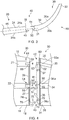
Figure 1 is a perspective view of an aircraft; -
Figure 2 is a schematic view of a leading edge of a wing tip with a wing tip device; -
Figure 3 is a schematic view of the wing tip and wing tip device shown inFigure 2 with the wing tip device disengaged from the wing tip; -
Figure 4 is a schematic partial cut-away plan view of the wing tip and part of wing tip device shown inFigure 3 ; -
Figure 5 is a schematic plan view of the wing tip and part of wing tip device shown inFigure 3 ; -
Figure 6 is a perspective view of part of the wing tip device shown inFigure 2 , with spigots for mounting with the wing tip shown; -
Figure 7 is a plan view of the wing tip device shown inFigure 2 ; -
Figure 8A is a perspective view of an outboard end of the wing tip shown inFigure 2 showing spigot retainers for receiving the spigots of the wing tip device shown; -
Figure 8B is a schematic view of the spigot retainers shown inFigure 8A ; -
Figure 9A is a schematic plan view of the wing tip and part of wing tip device shown inFigure 3 in a first partially assembled condition with a first spigot received by a first spigot retainer; -
Figure 9B is a schematic plan view of the wing tip and part of wing tip device shown inFigure 9A in a second partially assembled condition with first and second spigots received by first and second spigot retainers; and -
Figure 9C is a schematic plan view of the wing tip and part of wing tip device shown inFigure 9A in a third partially assembled condition with first, second and third spigots received by first, second and third spigot retainers. - An
aircraft 10 is shown inFigure 1 . Theaircraft 10 includes afuselage 11. Twowings 12 extend from thefuselage 11. It will be appreciated that thefuselage 11 andwings 12 may take a variety of different planned formed shapes and profiles depending on the particular application. Eachwing 12 has awing root 13 at the juncture with thefuselage 11. Thewing 12 has awing tip 20 at a distal end to thewing root 13. Thewing 12 has aleading edge 15 and a trailingedge 16. Thewing 12 comprises awing box 17. The wing box forms the main body of thewing 12. - In the following description, the term "front" refers to components towards the leading edge of the wing, and the term "rear" refers to components towards the trailing edge of the wing. The terms "forward" and "rearward" shall be construed accordingly. The position of features may be construed relative to other components, for example a forward component may be disposed on a forward side of another component, but towards the rear of the wing. The trailing edge relates to a rearmost section aft of the rear spar.
- One of the
wings 12 will be described herein. Referring toFigure 2 , thewing tip 20 is formed by the end of thewing 12. Awing tip device 30 is at thewing tip 20. In this example thewing tip device 30 is a winglet. Thewing tip 20 terminates at anoutboard end 18. Thewing tip device 30 extends from thewing tip 20. Thewing tip device 30 extends from theoutboard end 18. - The
wing 12 has a spanwise axis which extends in a direction from thewing root 13 to thewing tip 20. Thewing tip device 30 extends in a spanwise direction from thewing tip 20. Thewing 12 has a chordwise axis which extends in a direction from the leadingedge 15 to the trailingedge 16. Thewing 12 andwing tip device 30 each experience an aerodynamic lift force which acts through the centre of pressure. - The
wing tip device 30 is attached to thewing tip 20 at theoutboard end 18. Thewing tip 30 is shown inFigures 3 and7 . A mounting arrangement 40 (as shown inFigures 1 to 8B ) mounts thewing tip device 30 to thewing tip 20. Aerodynamic forces act on thewing tip device 30, and so thewing tip device 30 is stably attached to theoutboard end 18 by the mountingarrangement 40. A torque may act on thewing tip device 30 to urge rotation of thewing tip device 30 about an axis extending in a spanwise direction. A torque may act on thewing tip device 30 to urge rotation of thewing tip device 30 about an axis extending in a chordwise direction. - In
Figures 2 to 4 , awing assembly 19 is shown in schematic form comprising thewing tip 20 and thewing tip device 30. - The
wing tip 20 comprises aforward wing spar 21 and arearward wing spar 22. Each of the forward and rearward spars 21, 22 run in a generally spanwise direction. The forward and rearward wing spars 21, 22 converge along the span of the wing towards thewing tip 20. A series of ribs are positioned along the wing span and extend in the direction of the wing chord. Thewing tip 20 is covered by awing skin 24 comprising a wingupper cover 24a and a winglower cover 24b. The spars and ribs are covered by the wing skin primarily designed to present an aerodynamic surface to the airflow. Thewing tip 20 terminates at theoutboard end 18. - The
wing tip 20 has anend rib 26. Theend rib 26 extends between the forward and rearward wing spars 21, 22. Theend rib 26 is at theoutboard end 18. Theend rib 26 is exposed when thewing tip device 30 is removed from thewing tip 20. - The
wing tip 20 has a trailingedge end rib 27. The trailingedge end rib 27 is disposed rearward of therearward wing spar 22. The trailingedge end rib 27 extends from therearward wing spar 22. The trailingedge end rib 27 is at theoutboard end 18. The trailingedge end rib 27 is exposed when thewing tip device 30 is removed from thewing tip 20. - The
wing tip device 30, in this embodiment the winglet, comprises a wingtip device root 31 and afree end 32 distanced from and vertically spaced from the wingtip device root 31. - The
wing tip device 30 comprises afront device spar 33 and arear device spar 34. Thefront device spar 33 extends from a position partway between thefree end 32 and thedevice root 31 and extends to thedevice root 31. Thefront device spar 33 is disposed towards adevice leading edge 35. The rear device spar 34 runs from the position midway along thewing tip device 30 towards thedevice root 31. Therear device spar 34 diverges from the front device spar 33 towards thedevice root 31. Therear device spar 34 is disposed substantially midway along thedevice root 31 at thedevice root 31 in the chordwise direction. Therear device spar 34 is disposed rearwardly of the front device spar 33 towards adevice trailing edge 36. - A wing
tip device skin 39 covers thewing tip device 30 in order to present an aerodynamic surface to the airflow. The wingtip device skin 39 has anupper device cover 39a and alower device cover 39b. - The
wing tip device 30 has aroot rib 37. Theroot rib 37 extends between the front and rear device spars 33, 34. Theroot rib 37 is at thedevice root 31. Theroot rib 37 is exposed when thewing tip device 30 is removed from thewing tip 20. - The
wing tip device 30 has aclosing rib 38. The closingrib 38 is disposed rearward of therear device spar 34. The closingrib 38 extends from therear device spar 34. The closingrib 38 is at thedevice root 31. The closingrib 38 is exposed when thewing tip device 30 is removed from thewing tip 20. - The mounting
arrangement 40 comprises afirst connector 41, asecond connector 42 and athird connector 43. The mountingarrangement 40 comprises a first, upper, butt-strap 44 and a second, lower, butt-strap 45. As shown inFigure 3 , the wing tip and the wing tip device together define aspanwise axis 46. - Turning to
Figures 3, 4 and6 , it will be apparent that thewing tip device 30 attaches to thewing tip 20 at three primary attachment points A, B and C. - The
front device spar 33 attaches to the forward wing spar 21 viafirst connector 41 at attachment point A. Therear device spar 34 attaches to therearward wing spar 22 viasecond connector 42 at attachment point B. The wing tipdevice trailing edge 36 attaches to thewing trailing edge 16 viathird connector 43 at attachment point C. The first, second andthird connectors device root 31. - The
first connector 41 comprises as a spigot mounting formation including afirst spigot 50. Thefirst spigot 50 protrudes from thedevice root 31. Thefirst spigot 50 includes anelongate pin 51. Thefirst spigot 50 is on therear device spar 34. A first spigot fitting 52 mounts thefirst spigot 50 to aroot end 34a of therear device spar 34. The first spigot fitting 52 is associated with therear device spar 34. Loading through therear device spar 34 is able to act through thefirst spigot 50. Thefirst spigot 50 extends in a spanwise direction from theroot end 34a. Thefirst spigot 50 has a first spigotfree end 53. The first spigotfree end 53 is at a distal end of thefirst spigot 50 to the first spigot fitting 52. Thefirst spigot 50 defines a first elongate axis from the first spigot fitting 52 to the first spigotfree end 53. - The
first connector 41 comprises afirst spigot retainer 54. Thefirst spigot retainer 54 is configured to receive thefirst spigot 50. Thefirst spigot retainer 54 is on thewing tip 20. Thefirst spigot retainer 54 is at theoutboard end 18. Thefirst spigot retainer 54 is on therearward wing spar 22. Thefirst spigot retainer 54 is associated with therearward wing spar 22. Loading through therearward wing spar 22 is able to act through thefirst spigot retainer 54. - The
first spigot retainer 54 comprises abush 55. Thebush 55 is formed from bronze, although other suitable materials may be used. Thebush 55 comprises afirst retainer hole 56, as shown inFigures 8A and 8B . Thebush 55 defines a loading surface. Thefirst retainer hole 56 has dimensions which are configured to substantially conform with a diameter of thefirst spigot 50 in both directions parallel to and perpendicular to the chordwise direction. Thefirst retainer hole 56 has a diameter to form a tight fit with thefirst spigot 50. As such, thefirst connector 41 acts as a locking pin spigot in which thefirst connector 50 is able to react to side forces, and so all degrees of freedom are constrained. In particular, there is no ability to move in a spanwise or chordwise direction. - The
second connector 42 comprises as a spigot mounting formation including asecond spigot 60. Thesecond spigot 60 protrudes from thedevice root 31. Thesecond spigot 60 includes an elongate pin 61. Thesecond spigot 60 is on thefront device spar 33. A second spigot fitting 62 mounts thesecond spigot 60 to aroot end 33a of thefront device spar 34. The second spigot fitting 62 is associated with thefront device spar 33a. Loading through thefront device spar 33a is able to act through thesecond spigot 60. Thesecond spigot 60 extends in a spanwise direction from theroot end 33a. Thesecond spigot 60 has a second spigotfree end 63. The second spigotfree end 63 is at a distal end of thesecond spigot 60 to the second spigot fitting 62. Thesecond spigot 60 defines a second elongate axis from the second spigot fitting 62 to the second spigotfree end 63. - The
second connector 42 comprises asecond spigot retainer 64. Thesecond spigot retainer 64 is configured to receive thesecond spigot 60. Thesecond spigot retainer 64 is on thewing tip 20. Thesecond spigot retainer 64 is at theoutboard end 18. Thesecond spigot retainer 64 is on theforward wing spar 21. Thesecond spigot retainer 64 is associated with theforward wing spar 21. Loading through the forward wing spar 21 is able to act through thesecond spigot retainer 64. - The
second spigot retainer 64 comprises abush 65. Thebush 65 is formed from bronze, although other suitable materials may be used. Thebush 65 comprises asecond retainer slot 66, as shown inFigures 8A and 8B . Thebush 65 defines a loading surface. Thesecond retainer slot 66 is elongate and extends in a chordwise direction. The height of thesecond retainer slot 66 is configured to substantially conform with the diameter of thesecond spigot 60 in a direction perpendicular to the chordwise direction. The length of thesecond retainer slot 66 is greater than the diameter of thesecond spigot 60. As such, the second connector is unable to react a side force in the chordwise direction within certain limits. - The release of certain degrees of freedom (e.g. the inability of the
second spigot 60 to react the side force) allows the system some relative movement to avoid thermally induced stresses whilst making the loads more predictable (moving towards a statically determinate system). For example, because the joint atsecond connector 42 does not need to react the side force, it can be made smaller as a result (i.e. can be optimised for a more predictable load case). - The
third connector 43 comprises athird spigot 70. Thethird spigot 70 protrudes from thedevice root 31. Thethird spigot 70 includes an elongate pin 71. Thethird spigot 70 is on theclosing rib 38. A third spigot fitting 72 mounts thethird spigot 70 to aninboard face 38a of theclosing rib 38. The third spigot fitting 72 is associated with the closingrib 38. Loading on thedevice trailing edge 36 is able to act through thethird spigot 70. Such loading may result from aerodynamic forces acting on thewing tip device 30. Thethird spigot 70 extends in a spanwise direction from theroot end 33a. Thethird spigot 70 has a third spigotfree end 73. The third spigotfree end 73 is at a distal end of thethird spigot 70 to the third spigot fitting 72. Thethird spigot 70 defines a third elongate axis from the third spigot fitting 72 to the third spigotfree end 73. - The
third connector 43 comprises as a spigot mounting formation including athird spigot retainer 74. Thethird spigot retainer 74 is configured to receive thethird spigot 70. Thethird spigot retainer 74 is on thewing tip 20. Thethird spigot retainer 74 is at theoutboard end 18. Thethird spigot retainer 74 is on the trailingedge end rib 27. Thethird spigot retainer 74 is associated with the trailingedge end rib 27. Loading through the trailingedge end rib 27 is able to act through thesecond spigot retainer 64. - The
third spigot retainer 74 mounts to anoutboard face 27a of the trailingedge end rib 27. Loading on thewing trailing edge 16 is able to act through thethird spigot retainer 74. Such loading may result from aerodynamic forces acting on thewing trailing edge 16. - The
third spigot retainer 74 comprises a bush 75. The bush 75 is formed from bronze, although other suitable materials may be used. The bush 75 comprises athird retainer slot 76, as shown inFigures 8A and 8B . The bush 75 is formed by awear plate 77. An aperture is formed through the trailing edge end rib which aligns to the mounting of thethird spigot retainer 74 to provide for thethird spigot 70 to extend therethrough. The bush 75 defines a loading surface. The thirdspigot retainer slot 76 is elongate and extends in a chordwise direction. The height of thethird retainer slot 76 is configured to substantially conform with the diameter of thethird spigot 70 in a direction perpendicular to the chordwise direction. The length of thethird retainer slot 76 is greater than the diameter of thethird spigot 70. As such, thethird connector 43 is unable to react a side force in the chordwise direction within certain limits. - The release of certain degrees of freedom (e.g. the inability of the
third spigot 70 to react the side force) allows the system some relative movement to avoid thermally induced stresses whilst making the loads more predictable (moving towards a statically determinate system). For example, because the joint atthird connector 43 does not need to react the side force, it can be made smaller as a result (i.e. can be optimised for a more predictable load case). - The loading acting through the
third spigot 70 is configured to be lower than that acting through the first andsecond spigots third connector 43 is configured to react loading through thewing trailing edge 16 and thedevice trailing edge 36. As such, thethird connector 43 reacts forces acting on thewing tip 20 andwing tip device 30 aft of therearward wing spar 22 andrear device spar 34. Thethird connector 43 acts to ensure that thewing skin 24 and wingtip device skin 39 are maintained in alignment. Thewing trailing edge 16 and thedevice trailing edge 36 are not load bearing and conventionally may flutter during flight. The provision of thethird connector 43 ensures that thedevice trailing edge 36 and thewing trailing edge 16 move together, minimising the creation of gaps between the surfaces of thewing tip device 30 and thewing tip 20 during flight. As such aerodynamic efficiency at the juncture of thewing tip 20 andwing tip device 30 is maximised. Thethird connector 43 acts through ribs at the wing tip and wing tip device and so forces acting through the skins are minimised. - The upper and lower butt-
straps arrangement 40 extend between thewing tip 20 andwing tip device 30 when assembled. Theupper butt strap 44 extends between theupper cover 24a of thewing skin 24 and theupper cover 39a of thedevice skin 39. Theupper butt strap 44 is fixedly mounted between theupper cover 24a of thewing skin 24 and theupper cover 39a of thedevice skin 39 and acts as a splice plate. Thelower butt strap 45 extends between thelower cover 24b of thewing skin 24 and thelower cover 39b of thedevice skin 39. Thelower butt strap 45 is fixedly mounted between thelower cover 24b of thewing skin 24 and thelower cover 39b of thedevice skin 39 and acts as a splice plate. - In the present embodiment, the
wing skin 24 is a metallic skin and the wingtip device skin 39 is a composite skin. Theupper butt strap 44 is a metallic butt-strap and is mounted to the composite wingtip device skin 39 prior to assembly of thewing tip 20 andwing tip device 30. The lower butt-strap 45 is a composite butt-strap and is mounted to themetallic wing skin 24 prior to assembly of thewing tip 20 andwing tip device 30. When thewing tip 20 andwing tip device 30 are brought together, this arrangement assists alignment of the butt-straps - Each
spigot spanwise axis 46 defined by thewing tip 20 and thewing tip device 30. The elongate axis of eachspigot outboard end 18 of thewing tip 20 and thedevice root 31 of thewing tip device 30. Eachspigot device root 31. That is, each spigot is inclined towards the plane of theupper cover 24a of thewing 12 away from thedevice root 31, when assembled. The offset angle is in the range of 2 to 6 degrees. In the present embodiment, the offset angle is 4 degrees. This arrangement allows thewing tip device 30 to be presented to thewing tip 20 from below during assembly. - Each
connector wing tip 20 andwing tip device 30 are in an assembled condition, in which the respective spigot is received by the respective spigot retainer in a male/female connection, and a disengaged condition, when thewing tip 20 andwing tip device 30 are in an assembled condition, and in which the respective spigot is withdrawn from the respective spigot retainer. - The first, second and
third spigots wing tip device 30 by differing extents. Thethird spigot 70 upstands from a plane extending in a chordwise direction of thewing tip device 30. The length of thethird spigot 70 from the plane to the third spigotfree end 73 is less than the length of thefirst spigot 70 from the plane to the first spigotfree end 53. The length of thesecond spigot 60 from the plane to the second spigotfree end 63 is greater than the length of thethird spigot 70 from the plane to the third spigotfree end 73. Thefirst spigot 50 protrudes further outwardly than thesecond spigot 60. Thesecond spigot 60 protrudes further outwardly than thethird spigot 70. - It will be noted that because the present invention only uses three attachment points, and by providing the first and third spigots in chordwise extending spigot receiving slots, it is possible to constrain the wing tip device in a manner which makes the system statically determinate. Therefore, each attachment point can be designed around a known load case. This offers an advantage over the prior art in which generally a high number of fixings are used for load-bearing purposes and consequently a statically indeterminate system is formed in which the exact load case on each attachment point is unknown. Therefore each attachment point has to be over-engineered to cope with the worst possible case.
- Referring to
Figures 9A to 9C , a method of attachment of a wing tip device is shown. Thewing assembly 19 is shown comprising thewing tip 20 and awing tip device 30. Thewing tip device 30 is attached to thewing tip 20 at attachment points B, A, C in a chordwise direction from leading edge to trailing edge. In thewing assembly 19, the attachment points B, A and C have their horizontal chordwise axes (parallel to axis Y) of rotation aligned as will be described below. Thewing tip device 30 is moved proximate thewing tip 20 on a trolley jack or similar. The jack is elevated to move thewing tip device 30 such that the first, second andthird spigots wing tip 20. Thewing tip device 30 may be presented from slightly below thewing tip 20 due to the offset angular arrangement of thespigots - When the
wing tip device 30 is brought into engagement with thewing tip 20, thefirst connector 41 is configured to initially move into its engaged condition prior to the second andthird connectors Figure 9A . As a result, it is relatively straightforward to align a single attachment point. When thefree end 53 of thefirst spigot 50 is received by thefirst spigot retainer 54 sideways movement is restricted due to the close fit of the two components. As such, thewing tip device 20 is easily moved by rotation to align thesecond spigot 60 with thesecond spigot retainer 63. The wing tip device is then further moved in an axial direction so that the first andsecond spigots Figure 9B . As such the load bearing requirements may be carried by the first andsecond connectors third connector 70 during assembly. Rotation of thewing tip device 30 about thewing tip 20 is prevented by the first andsecond connectors third spigot 70 is engaged with itsrespective spigot retainer 74, as shown inFigure 9C . Thewing tip device 30 is then fully assembled with thewing tip 20. The butt-straps skins - The above described arrangement simplifies assembly of the wing tip device with the wing tip. As such, each connector is aligned and engaged sequentially.
- When the
wing tip device 30 is brought into engagement with the wing tip, the first connector may be configured to move into its engaged condition prior to the second connector moving into its engaged condition. - When the wing tip device is brought into engagement with the wing tip, the second connector may be configured to move into its engaged condition prior to the third connector moving into its engaged condition.
- This arrangement simplifies assembly of the wing tip device with the wing tip. As such, each connector is aligned and engaged sequentially. Furthermore, the arrangement ensures that the connectors on the main load bearing members are engaged first.
- Although in the above described embodiments, the spigots are disposed on the wing tip device, and the spigot retainers are on the wing tip, it will be understood that the arrangement of one or more of the connectors may be reversed. For example, one or more spigots may be on the wing tip. An advantage of the spigots being on the wing tip is that the ability of the aircraft to fly without one or more wing tip assemblies assembled on the aircraft is enhanced. Furthermore, ease of alignment of the spigot and spigot retainers, and therefore a reduction in assembly time, is enhanced by locating the spigots on the wing tip device.
- Where the word 'or' appears this is to be construed to mean 'and/or' such that items referred to are not necessarily mutually exclusive and may be used in any appropriate combination.
- Although the invention has been described above with reference to one or more preferred embodiments, it will be appreciated that various changes or modifications may be made without departing from the scope of the invention as defined in the appended claims.
Claims (15)
- An aircraft assembly comprising:a wing tip device connected to a wing tip by a first connector, a second connector and a third connector, the wing tip device comprising a front device spar and a rear device spar, wherein:the first connector is associated with the rear device spar,the second connector is spaced apart, in a chordwise direction, forward of the first connector,the third connector is spaced apart, in a chordwise direction, rearward of the first connector, andthe third connector comprises a spigot mounting formation.
- The aircraft assembly of claim 1, wherein the second connector is associated with the front device spar.
- The aircraft assembly of claim 1 or 2, wherein the wing tip comprises a wing trailing edge, and the wing tip device comprises a device trailing edge and the third connector is configured to connect the device trailing edge with the wing trailing edge.
- The aircraft assembly of any of claims 1 to 3, wherein the wing tip device comprises a closing rib located aft of the rear device spar, wherein the spigot mounting formation is associated with the closing rib.
- The aircraft assembly of any of claims 1 to 4, wherein the wing tip comprises a forward wing spar and a rearward wing spar, wherein the first connector is associated with the rearward wing spar.
- The aircraft assembly of claim 5, wherein the wing tip comprises a trailing edge end rib located aft of rearward wing spar, wherein the spigot mounting formation is associated with the trailing edge end rib.
- The aircraft assembly of any of claims 1 to 6, wherein the spigot mounting formation comprises a spigot associated with the wing tip device, and a spigot retainer associated with the wing tip for receiving the spigot in a male/female connection.
- The aircraft assembly of claim 7, wherein the spigot retainer comprises an elongate retainer slot extending in the chordwise direction.
- The aircraft assembly of any preceding claim, wherein the first connector comprises a first spigot mounting formation, and the second connector comprises a second spigot mounting formation, wherein the spigot mounting formation of any preceding claim is a third spigot mounting formation.
- The aircraft assembly of claim 9, wherein the first spigot mounting formation comprises a first spigot associated with the wing tip device or the wing tip, and a first spigot retainer associated with the other of the wing tip device or the wing tip; the second spigot mounting formation comprises a second spigot associated with the wing tip device or the wing tip, and a second spigot retainer associated with the other of the wing tip device or the wing tip; and wherein the spigot mounting formation of any preceding claim comprises a third spigot and a third spigot retainer.
- The aircraft assembly of any preceding claim, in which, when the wing tip device is brought into engagement with the wing tip, the first connector is configured to move into an engaged condition prior to the second connector moving into an engaged condition, and the second connector is configured to move into an engaged condition prior to the third connector moving into an engaged condition.
- The aircraft assembly of any of claims 7, 8, 10 or 11, in which, when assembled, the wing tip and the wing tip device together define a spanwise axis, wherein an elongate axis of the or each spigot is at an offset angle to the spanwise axis at the juncture of the wing tip and the wing tip device and, optionally, wherein the offset angle is 2 to 6 degrees and, optionally, wherein the offset angle is 4 degrees.
- The aircraft assembly of any preceding claim, wherein the wing tip comprises a wing skin, and the wing tip device comprises a wing tip device skin, and the aircraft assembly comprises a butt-strap between the wing skin and the wing tip device skin.
- The aircraft assembly of claim 13, wherein the or each butt-strap is disposed only at or forward of the first connector.
- A method of assembling a wing tip device and a wing tip of a wing, the method comprising:locating the wing tip device relative to the wing tip,engaging a first spigot associated with the rear device spar and one of the wing tip device or the wing tip with a first spigot retainer associated with the other of the wing tip device or the wing tip,subsequently, engaging a second spigot spaced apart, in a chordwise direction, forward of the first spigot and associated with one of the wing tip device or the wing tip with a second spigot retainer associated with the other of the wing tip device or the wing tip, andsubsequently, engaging a third spigot spaced apart, in a chordwise direction, rearward of the first spigot and associated with one of the wing tip device or the wing tip with a third spigot retainer associated with the other of the wing tip device or the wing tip.
Applications Claiming Priority (1)
| Application Number | Priority Date | Filing Date | Title |
|---|---|---|---|
| GB1717197.6A GB2568229B (en) | 2017-10-19 | 2017-10-19 | An aircraft assembly including a wingtip device |
Publications (2)
| Publication Number | Publication Date |
|---|---|
| EP3473539A1 true EP3473539A1 (en) | 2019-04-24 |
| EP3473539B1 EP3473539B1 (en) | 2023-03-08 |
Family
ID=60481584
Family Applications (1)
| Application Number | Title | Priority Date | Filing Date |
|---|---|---|---|
| EP18196230.9A Active EP3473539B1 (en) | 2017-10-19 | 2018-09-24 | An aircraft assembly including a wingtip device |
Country Status (6)
| Country | Link |
|---|---|
| US (2) | US11260964B2 (en) |
| EP (1) | EP3473539B1 (en) |
| KR (1) | KR20190044012A (en) |
| CN (1) | CN109677585B (en) |
| ES (1) | ES2942763T3 (en) |
| GB (1) | GB2568229B (en) |
Families Citing this family (5)
| Publication number | Priority date | Publication date | Assignee | Title |
|---|---|---|---|---|
| GB2550403A (en) | 2016-05-19 | 2017-11-22 | Airbus Operations Ltd | Aerofoil body with integral curved spar-cover |
| GB2568229B (en) * | 2017-10-19 | 2020-01-29 | Airbus Operations Ltd | An aircraft assembly including a wingtip device |
| CN116215592B (en) * | 2023-03-24 | 2023-10-17 | 新创碳谷集团有限公司 | A connection structure, connection method and rail transit car body |
| US12473073B2 (en) * | 2023-12-20 | 2025-11-18 | The Boeing Company | Wingtip attachment with a reduction in in-tank work and aerodynamic drag |
| CN120057248B (en) * | 2025-04-17 | 2025-11-28 | 白鲸航线(常州)科技有限公司 | Wing tip winglet and aircraft wing |
Citations (4)
| Publication number | Priority date | Publication date | Assignee | Title |
|---|---|---|---|---|
| US20070018049A1 (en) * | 2005-07-21 | 2007-01-25 | Stuhr Victor K | Integrated wingtip extensions for jet transport aircraft and other types of aircraft |
| US20120112005A1 (en) * | 2010-10-28 | 2012-05-10 | Airbus Operations Limited | Wing tip device attachment apparatus and method |
| WO2014065718A1 (en) * | 2012-10-22 | 2014-05-01 | Saab Ab | An integrated curved structure and winglet strength enhancement |
| EP3130534A1 (en) * | 2014-09-30 | 2017-02-15 | Commercial Aircraft Corporation Of China Ltd | Airplane wing assembly |
Family Cites Families (11)
| Publication number | Priority date | Publication date | Assignee | Title |
|---|---|---|---|---|
| IL101069A (en) * | 1991-02-25 | 1996-09-12 | Valsan Partners Purchase N Y | System for increasing airplane fuel mileage and airplane wing modification kit |
| US6161797A (en) * | 1996-11-25 | 2000-12-19 | Dugan Air Technologies, Inc. | Method and apparatus for reducing airplane noise |
| US7975965B2 (en) * | 2008-05-13 | 2011-07-12 | The Boeing Company | Wing tip joint in airfoils |
| AU2010350897B2 (en) * | 2010-04-12 | 2015-05-14 | Airbus Operations Gmbh | Fixed wing of an aircraft |
| GB201307066D0 (en) * | 2013-04-18 | 2013-05-29 | Airbus Operations Ltd | Winglet and braided composite spar |
| US9248921B2 (en) * | 2013-07-11 | 2016-02-02 | Spirit Aerosystems, Inc. | Method for mounting a pylon to an aircraft |
| EP3170742B1 (en) * | 2015-11-18 | 2018-02-21 | Airbus Operations GmbH | Foldable wing for an aircraft and aircraft having a foldable wing |
| GB2551311A (en) * | 2016-05-24 | 2017-12-20 | Airbus Operations Ltd | Winglet |
| CN106005369B (en) * | 2016-07-24 | 2018-07-03 | 尹鸿俊 | A kind of unmanned plane |
| US11014666B2 (en) * | 2016-09-23 | 2021-05-25 | Skydio, Inc. | Airframe |
| GB2568229B (en) * | 2017-10-19 | 2020-01-29 | Airbus Operations Ltd | An aircraft assembly including a wingtip device |
-
2017
- 2017-10-19 GB GB1717197.6A patent/GB2568229B/en not_active Expired - Fee Related
-
2018
- 2018-09-24 ES ES18196230T patent/ES2942763T3/en active Active
- 2018-09-24 EP EP18196230.9A patent/EP3473539B1/en active Active
- 2018-10-16 US US16/161,371 patent/US11260964B2/en active Active
- 2018-10-17 CN CN201811208303.7A patent/CN109677585B/en active Active
- 2018-10-18 KR KR1020180124591A patent/KR20190044012A/en not_active Withdrawn
-
2022
- 2022-01-12 US US17/647,761 patent/US11905001B2/en active Active
Patent Citations (4)
| Publication number | Priority date | Publication date | Assignee | Title |
|---|---|---|---|---|
| US20070018049A1 (en) * | 2005-07-21 | 2007-01-25 | Stuhr Victor K | Integrated wingtip extensions for jet transport aircraft and other types of aircraft |
| US20120112005A1 (en) * | 2010-10-28 | 2012-05-10 | Airbus Operations Limited | Wing tip device attachment apparatus and method |
| WO2014065718A1 (en) * | 2012-10-22 | 2014-05-01 | Saab Ab | An integrated curved structure and winglet strength enhancement |
| EP3130534A1 (en) * | 2014-09-30 | 2017-02-15 | Commercial Aircraft Corporation Of China Ltd | Airplane wing assembly |
Also Published As
| Publication number | Publication date |
|---|---|
| US11905001B2 (en) | 2024-02-20 |
| CN109677585B (en) | 2025-02-11 |
| US20190118930A1 (en) | 2019-04-25 |
| US20220135212A1 (en) | 2022-05-05 |
| CN109677585A (en) | 2019-04-26 |
| GB201717197D0 (en) | 2017-12-06 |
| KR20190044012A (en) | 2019-04-29 |
| ES2942763T3 (en) | 2023-06-06 |
| US11260964B2 (en) | 2022-03-01 |
| EP3473539B1 (en) | 2023-03-08 |
| GB2568229A (en) | 2019-05-15 |
| GB2568229B (en) | 2020-01-29 |
Similar Documents
| Publication | Publication Date | Title |
|---|---|---|
| US11905001B2 (en) | Wingtip to wing aircraft connection assembly | |
| US10745113B2 (en) | Wing tip device attachment apparatus and method | |
| EP3118104B1 (en) | Pinned fuselage-to-wing connection | |
| US7887009B2 (en) | Methods and systems for attaching aircraft wings to fuselages | |
| US11192624B2 (en) | Aerofoil structure and method of assembly | |
| CN107813921B (en) | Device comprising an aircraft wing and method for using the device | |
| US10661886B2 (en) | Wing structure for flying objects | |
| US12043397B2 (en) | Attachment concept for a fairing on an airfoil body such as a flap or a wing of an aircraft | |
| CN104417748A (en) | Upper joints between outboard wing boxes and wing center sections of aircraft wing assemblies | |
| EP3243742B1 (en) | Aircraft joint | |
| EP3546343B1 (en) | Wing flap with torque member and method for forming thereof | |
| JP7804468B2 (en) | Connector for connecting the center wing box of an aircraft to the bulkhead | |
| EP3130534B1 (en) | Airplane wing assembly | |
| EP3898409B1 (en) | Aircraft assembly having an integral spar-cover | |
| US11305861B2 (en) | Wing assembly mount | |
| CN111556843B (en) | Load bearing structure to be mounted on an engine core | |
| CN122035277A (en) | Connection structure of fuselage floor and central wing and wing coupling assembling | |
| CN117622465A (en) | Aircraft with replaceable wing tips and method of replacing wing tips |
Legal Events
| Date | Code | Title | Description |
|---|---|---|---|
| PUAI | Public reference made under article 153(3) epc to a published international application that has entered the european phase |
Free format text: ORIGINAL CODE: 0009012 |
|
| STAA | Information on the status of an ep patent application or granted ep patent |
Free format text: STATUS: THE APPLICATION HAS BEEN PUBLISHED |
|
| AK | Designated contracting states |
Kind code of ref document: A1 Designated state(s): AL AT BE BG CH CY CZ DE DK EE ES FI FR GB GR HR HU IE IS IT LI LT LU LV MC MK MT NL NO PL PT RO RS SE SI SK SM TR |
|
| AX | Request for extension of the european patent |
Extension state: BA ME |
|
| STAA | Information on the status of an ep patent application or granted ep patent |
Free format text: STATUS: REQUEST FOR EXAMINATION WAS MADE |
|
| 17P | Request for examination filed |
Effective date: 20190925 |
|
| RBV | Designated contracting states (corrected) |
Designated state(s): AL AT BE BG CH CY CZ DE DK EE ES FI FR GB GR HR HU IE IS IT LI LT LU LV MC MK MT NL NO PL PT RO RS SE SI SK SM TR |
|
| STAA | Information on the status of an ep patent application or granted ep patent |
Free format text: STATUS: EXAMINATION IS IN PROGRESS |
|
| 17Q | First examination report despatched |
Effective date: 20210323 |
|
| GRAP | Despatch of communication of intention to grant a patent |
Free format text: ORIGINAL CODE: EPIDOSNIGR1 |
|
| STAA | Information on the status of an ep patent application or granted ep patent |
Free format text: STATUS: GRANT OF PATENT IS INTENDED |
|
| INTG | Intention to grant announced |
Effective date: 20220923 |
|
| RIC1 | Information provided on ipc code assigned before grant |
Ipc: B64F 5/10 20170101ALI20220909BHEP Ipc: B64C 23/06 20060101ALI20220909BHEP Ipc: B64C 3/18 20060101AFI20220909BHEP |
|
| GRAS | Grant fee paid |
Free format text: ORIGINAL CODE: EPIDOSNIGR3 |
|
| GRAA | (expected) grant |
Free format text: ORIGINAL CODE: 0009210 |
|
| STAA | Information on the status of an ep patent application or granted ep patent |
Free format text: STATUS: THE PATENT HAS BEEN GRANTED |
|
| AK | Designated contracting states |
Kind code of ref document: B1 Designated state(s): AL AT BE BG CH CY CZ DE DK EE ES FI FR GB GR HR HU IE IS IT LI LT LU LV MC MK MT NL NO PL PT RO RS SE SI SK SM TR |
|
| REG | Reference to a national code |
Ref country code: CH Ref legal event code: EP Ref country code: AT Ref legal event code: REF Ref document number: 1552429 Country of ref document: AT Kind code of ref document: T Effective date: 20230315 |
|
| REG | Reference to a national code |
Ref country code: DE Ref legal event code: R096 Ref document number: 602018046903 Country of ref document: DE |
|
| REG | Reference to a national code |
Ref country code: IE Ref legal event code: FG4D |
|
| REG | Reference to a national code |
Ref country code: ES Ref legal event code: FG2A Ref document number: 2942763 Country of ref document: ES Kind code of ref document: T3 Effective date: 20230606 |
|
| REG | Reference to a national code |
Ref country code: LT Ref legal event code: MG9D |
|
| REG | Reference to a national code |
Ref country code: NL Ref legal event code: MP Effective date: 20230308 |
|
| PG25 | Lapsed in a contracting state [announced via postgrant information from national office to epo] |
Ref country code: RS Free format text: LAPSE BECAUSE OF FAILURE TO SUBMIT A TRANSLATION OF THE DESCRIPTION OR TO PAY THE FEE WITHIN THE PRESCRIBED TIME-LIMIT Effective date: 20230308 Ref country code: NO Free format text: LAPSE BECAUSE OF FAILURE TO SUBMIT A TRANSLATION OF THE DESCRIPTION OR TO PAY THE FEE WITHIN THE PRESCRIBED TIME-LIMIT Effective date: 20230608 Ref country code: LV Free format text: LAPSE BECAUSE OF FAILURE TO SUBMIT A TRANSLATION OF THE DESCRIPTION OR TO PAY THE FEE WITHIN THE PRESCRIBED TIME-LIMIT Effective date: 20230308 Ref country code: LT Free format text: LAPSE BECAUSE OF FAILURE TO SUBMIT A TRANSLATION OF THE DESCRIPTION OR TO PAY THE FEE WITHIN THE PRESCRIBED TIME-LIMIT Effective date: 20230308 Ref country code: HR Free format text: LAPSE BECAUSE OF FAILURE TO SUBMIT A TRANSLATION OF THE DESCRIPTION OR TO PAY THE FEE WITHIN THE PRESCRIBED TIME-LIMIT Effective date: 20230308 |
|
| PG25 | Lapsed in a contracting state [announced via postgrant information from national office to epo] |
Ref country code: SE Free format text: LAPSE BECAUSE OF FAILURE TO SUBMIT A TRANSLATION OF THE DESCRIPTION OR TO PAY THE FEE WITHIN THE PRESCRIBED TIME-LIMIT Effective date: 20230308 Ref country code: NL Free format text: LAPSE BECAUSE OF FAILURE TO SUBMIT A TRANSLATION OF THE DESCRIPTION OR TO PAY THE FEE WITHIN THE PRESCRIBED TIME-LIMIT Effective date: 20230308 Ref country code: GR Free format text: LAPSE BECAUSE OF FAILURE TO SUBMIT A TRANSLATION OF THE DESCRIPTION OR TO PAY THE FEE WITHIN THE PRESCRIBED TIME-LIMIT Effective date: 20230609 Ref country code: FI Free format text: LAPSE BECAUSE OF FAILURE TO SUBMIT A TRANSLATION OF THE DESCRIPTION OR TO PAY THE FEE WITHIN THE PRESCRIBED TIME-LIMIT Effective date: 20230308 |
|
| PG25 | Lapsed in a contracting state [announced via postgrant information from national office to epo] |
Ref country code: SM Free format text: LAPSE BECAUSE OF FAILURE TO SUBMIT A TRANSLATION OF THE DESCRIPTION OR TO PAY THE FEE WITHIN THE PRESCRIBED TIME-LIMIT Effective date: 20230308 Ref country code: RO Free format text: LAPSE BECAUSE OF FAILURE TO SUBMIT A TRANSLATION OF THE DESCRIPTION OR TO PAY THE FEE WITHIN THE PRESCRIBED TIME-LIMIT Effective date: 20230308 Ref country code: PT Free format text: LAPSE BECAUSE OF FAILURE TO SUBMIT A TRANSLATION OF THE DESCRIPTION OR TO PAY THE FEE WITHIN THE PRESCRIBED TIME-LIMIT Effective date: 20230710 Ref country code: EE Free format text: LAPSE BECAUSE OF FAILURE TO SUBMIT A TRANSLATION OF THE DESCRIPTION OR TO PAY THE FEE WITHIN THE PRESCRIBED TIME-LIMIT Effective date: 20230308 Ref country code: CZ Free format text: LAPSE BECAUSE OF FAILURE TO SUBMIT A TRANSLATION OF THE DESCRIPTION OR TO PAY THE FEE WITHIN THE PRESCRIBED TIME-LIMIT Effective date: 20230308 |
|
| PG25 | Lapsed in a contracting state [announced via postgrant information from national office to epo] |
Ref country code: SK Free format text: LAPSE BECAUSE OF FAILURE TO SUBMIT A TRANSLATION OF THE DESCRIPTION OR TO PAY THE FEE WITHIN THE PRESCRIBED TIME-LIMIT Effective date: 20230308 Ref country code: PL Free format text: LAPSE BECAUSE OF FAILURE TO SUBMIT A TRANSLATION OF THE DESCRIPTION OR TO PAY THE FEE WITHIN THE PRESCRIBED TIME-LIMIT Effective date: 20230308 Ref country code: IS Free format text: LAPSE BECAUSE OF FAILURE TO SUBMIT A TRANSLATION OF THE DESCRIPTION OR TO PAY THE FEE WITHIN THE PRESCRIBED TIME-LIMIT Effective date: 20230708 |
|
| REG | Reference to a national code |
Ref country code: DE Ref legal event code: R097 Ref document number: 602018046903 Country of ref document: DE |
|
| PLBE | No opposition filed within time limit |
Free format text: ORIGINAL CODE: 0009261 |
|
| STAA | Information on the status of an ep patent application or granted ep patent |
Free format text: STATUS: NO OPPOSITION FILED WITHIN TIME LIMIT |
|
| PG25 | Lapsed in a contracting state [announced via postgrant information from national office to epo] |
Ref country code: SI Free format text: LAPSE BECAUSE OF FAILURE TO SUBMIT A TRANSLATION OF THE DESCRIPTION OR TO PAY THE FEE WITHIN THE PRESCRIBED TIME-LIMIT Effective date: 20230308 Ref country code: DK Free format text: LAPSE BECAUSE OF FAILURE TO SUBMIT A TRANSLATION OF THE DESCRIPTION OR TO PAY THE FEE WITHIN THE PRESCRIBED TIME-LIMIT Effective date: 20230308 |
|
| 26N | No opposition filed |
Effective date: 20231211 |
|
| REG | Reference to a national code |
Ref country code: AT Ref legal event code: UEP Ref document number: 1552429 Country of ref document: AT Kind code of ref document: T Effective date: 20230308 |
|
| REG | Reference to a national code |
Ref country code: CH Ref legal event code: PL |
|
| PG25 | Lapsed in a contracting state [announced via postgrant information from national office to epo] |
Ref country code: LU Free format text: LAPSE BECAUSE OF NON-PAYMENT OF DUE FEES Effective date: 20230924 |
|
| REG | Reference to a national code |
Ref country code: BE Ref legal event code: MM Effective date: 20230930 |
|
| PG25 | Lapsed in a contracting state [announced via postgrant information from national office to epo] |
Ref country code: LU Free format text: LAPSE BECAUSE OF NON-PAYMENT OF DUE FEES Effective date: 20230924 Ref country code: IT Free format text: LAPSE BECAUSE OF FAILURE TO SUBMIT A TRANSLATION OF THE DESCRIPTION OR TO PAY THE FEE WITHIN THE PRESCRIBED TIME-LIMIT Effective date: 20230308 Ref country code: MC Free format text: LAPSE BECAUSE OF FAILURE TO SUBMIT A TRANSLATION OF THE DESCRIPTION OR TO PAY THE FEE WITHIN THE PRESCRIBED TIME-LIMIT Effective date: 20230308 |
|
| REG | Reference to a national code |
Ref country code: IE Ref legal event code: MM4A |
|
| PG25 | Lapsed in a contracting state [announced via postgrant information from national office to epo] |
Ref country code: IE Free format text: LAPSE BECAUSE OF NON-PAYMENT OF DUE FEES Effective date: 20230924 |
|
| PG25 | Lapsed in a contracting state [announced via postgrant information from national office to epo] |
Ref country code: CH Free format text: LAPSE BECAUSE OF NON-PAYMENT OF DUE FEES Effective date: 20230930 |
|
| PG25 | Lapsed in a contracting state [announced via postgrant information from national office to epo] |
Ref country code: IE Free format text: LAPSE BECAUSE OF NON-PAYMENT OF DUE FEES Effective date: 20230924 Ref country code: FR Free format text: LAPSE BECAUSE OF NON-PAYMENT OF DUE FEES Effective date: 20230930 Ref country code: CH Free format text: LAPSE BECAUSE OF NON-PAYMENT OF DUE FEES Effective date: 20230930 |
|
| PG25 | Lapsed in a contracting state [announced via postgrant information from national office to epo] |
Ref country code: BE Free format text: LAPSE BECAUSE OF NON-PAYMENT OF DUE FEES Effective date: 20230930 |
|
| PG25 | Lapsed in a contracting state [announced via postgrant information from national office to epo] |
Ref country code: BG Free format text: LAPSE BECAUSE OF FAILURE TO SUBMIT A TRANSLATION OF THE DESCRIPTION OR TO PAY THE FEE WITHIN THE PRESCRIBED TIME-LIMIT Effective date: 20230308 |
|
| PG25 | Lapsed in a contracting state [announced via postgrant information from national office to epo] |
Ref country code: BG Free format text: LAPSE BECAUSE OF FAILURE TO SUBMIT A TRANSLATION OF THE DESCRIPTION OR TO PAY THE FEE WITHIN THE PRESCRIBED TIME-LIMIT Effective date: 20230308 |
|
| PG25 | Lapsed in a contracting state [announced via postgrant information from national office to epo] |
Ref country code: CY Free format text: LAPSE BECAUSE OF FAILURE TO SUBMIT A TRANSLATION OF THE DESCRIPTION OR TO PAY THE FEE WITHIN THE PRESCRIBED TIME-LIMIT; INVALID AB INITIO Effective date: 20180924 |
|
| PG25 | Lapsed in a contracting state [announced via postgrant information from national office to epo] |
Ref country code: HU Free format text: LAPSE BECAUSE OF FAILURE TO SUBMIT A TRANSLATION OF THE DESCRIPTION OR TO PAY THE FEE WITHIN THE PRESCRIBED TIME-LIMIT; INVALID AB INITIO Effective date: 20180924 |
|
| PGFP | Annual fee paid to national office [announced via postgrant information from national office to epo] |
Ref country code: DE Payment date: 20250919 Year of fee payment: 8 |
|
| PGFP | Annual fee paid to national office [announced via postgrant information from national office to epo] |
Ref country code: GB Payment date: 20250919 Year of fee payment: 8 |
|
| PGFP | Annual fee paid to national office [announced via postgrant information from national office to epo] |
Ref country code: AT Payment date: 20250919 Year of fee payment: 8 |
|
| PG25 | Lapsed in a contracting state [announced via postgrant information from national office to epo] |
Ref country code: TR Free format text: LAPSE BECAUSE OF FAILURE TO SUBMIT A TRANSLATION OF THE DESCRIPTION OR TO PAY THE FEE WITHIN THE PRESCRIBED TIME-LIMIT Effective date: 20230308 |
|
| PGFP | Annual fee paid to national office [announced via postgrant information from national office to epo] |
Ref country code: ES Payment date: 20251030 Year of fee payment: 8 |