EP3473494B1 - Vehicle lamp lighting control device and vehicle lamp system - Google Patents
Vehicle lamp lighting control device and vehicle lamp system Download PDFInfo
- Publication number
- EP3473494B1 EP3473494B1 EP17813162.9A EP17813162A EP3473494B1 EP 3473494 B1 EP3473494 B1 EP 3473494B1 EP 17813162 A EP17813162 A EP 17813162A EP 3473494 B1 EP3473494 B1 EP 3473494B1
- Authority
- EP
- European Patent Office
- Prior art keywords
- section
- luminous intensity
- time
- light source
- light
- Prior art date
- Legal status (The legal status is an assumption and is not a legal conclusion. Google has not performed a legal analysis and makes no representation as to the accuracy of the status listed.)
- Active
Links
Images


Classifications
-
- H—ELECTRICITY
- H05—ELECTRIC TECHNIQUES NOT OTHERWISE PROVIDED FOR
- H05B—ELECTRIC HEATING; ELECTRIC LIGHT SOURCES NOT OTHERWISE PROVIDED FOR; CIRCUIT ARRANGEMENTS FOR ELECTRIC LIGHT SOURCES, IN GENERAL
- H05B45/00—Circuit arrangements for operating light-emitting diodes [LED]
- H05B45/10—Controlling the intensity of the light
-
- B—PERFORMING OPERATIONS; TRANSPORTING
- B60—VEHICLES IN GENERAL
- B60Q—ARRANGEMENT OF SIGNALLING OR LIGHTING DEVICES, THE MOUNTING OR SUPPORTING THEREOF OR CIRCUITS THEREFOR, FOR VEHICLES IN GENERAL
- B60Q1/00—Arrangement of optical signalling or lighting devices, the mounting or supporting thereof or circuits therefor
- B60Q1/26—Arrangement of optical signalling or lighting devices, the mounting or supporting thereof or circuits therefor the devices being primarily intended to indicate the vehicle, or parts thereof, or to give signals, to other traffic
- B60Q1/34—Arrangement of optical signalling or lighting devices, the mounting or supporting thereof or circuits therefor the devices being primarily intended to indicate the vehicle, or parts thereof, or to give signals, to other traffic for indicating change of drive direction
-
- B—PERFORMING OPERATIONS; TRANSPORTING
- B60—VEHICLES IN GENERAL
- B60Q—ARRANGEMENT OF SIGNALLING OR LIGHTING DEVICES, THE MOUNTING OR SUPPORTING THEREOF OR CIRCUITS THEREFOR, FOR VEHICLES IN GENERAL
- B60Q1/00—Arrangement of optical signalling or lighting devices, the mounting or supporting thereof or circuits therefor
- B60Q1/26—Arrangement of optical signalling or lighting devices, the mounting or supporting thereof or circuits therefor the devices being primarily intended to indicate the vehicle, or parts thereof, or to give signals, to other traffic
- B60Q1/34—Arrangement of optical signalling or lighting devices, the mounting or supporting thereof or circuits therefor the devices being primarily intended to indicate the vehicle, or parts thereof, or to give signals, to other traffic for indicating change of drive direction
- B60Q1/38—Arrangement of optical signalling or lighting devices, the mounting or supporting thereof or circuits therefor the devices being primarily intended to indicate the vehicle, or parts thereof, or to give signals, to other traffic for indicating change of drive direction using immovably-mounted light sources, e.g. fixed flashing lamps
- B60Q1/381—Arrangement of optical signalling or lighting devices, the mounting or supporting thereof or circuits therefor the devices being primarily intended to indicate the vehicle, or parts thereof, or to give signals, to other traffic for indicating change of drive direction using immovably-mounted light sources, e.g. fixed flashing lamps with several light sources activated in sequence, e.g. to create a sweep effect
-
- H—ELECTRICITY
- H05—ELECTRIC TECHNIQUES NOT OTHERWISE PROVIDED FOR
- H05B—ELECTRIC HEATING; ELECTRIC LIGHT SOURCES NOT OTHERWISE PROVIDED FOR; CIRCUIT ARRANGEMENTS FOR ELECTRIC LIGHT SOURCES, IN GENERAL
- H05B47/00—Circuit arrangements for operating light sources in general, i.e. where the type of light source is not relevant
- H05B47/10—Controlling the light source
- H05B47/16—Controlling the light source by timing means
-
- H—ELECTRICITY
- H05—ELECTRIC TECHNIQUES NOT OTHERWISE PROVIDED FOR
- H05B—ELECTRIC HEATING; ELECTRIC LIGHT SOURCES NOT OTHERWISE PROVIDED FOR; CIRCUIT ARRANGEMENTS FOR ELECTRIC LIGHT SOURCES, IN GENERAL
- H05B45/00—Circuit arrangements for operating light-emitting diodes [LED]
- H05B45/30—Driver circuits
- H05B45/32—Pulse-control circuits
- H05B45/325—Pulse-width modulation [PWM]
-
- Y—GENERAL TAGGING OF NEW TECHNOLOGICAL DEVELOPMENTS; GENERAL TAGGING OF CROSS-SECTIONAL TECHNOLOGIES SPANNING OVER SEVERAL SECTIONS OF THE IPC; TECHNICAL SUBJECTS COVERED BY FORMER USPC CROSS-REFERENCE ART COLLECTIONS [XRACs] AND DIGESTS
- Y02—TECHNOLOGIES OR APPLICATIONS FOR MITIGATION OR ADAPTATION AGAINST CLIMATE CHANGE
- Y02B—CLIMATE CHANGE MITIGATION TECHNOLOGIES RELATED TO BUILDINGS, e.g. HOUSING, HOUSE APPLIANCES OR RELATED END-USER APPLICATIONS
- Y02B20/00—Energy efficient lighting technologies, e.g. halogen lamps or gas discharge lamps
- Y02B20/40—Control techniques providing energy savings, e.g. smart controller or presence detection
Definitions
- the present invention relates to a technique for controlling the flashing of vehicular lamps used for applications such as turn signal lamps.
- a prior art of vehicular lamps used as turn signal lamps (winkers) is disclosed in, for example, JP 2014-139941 A .
- This prior art is intended, when a pair of headlights, turn signal lamps or the like are configured using LEDs, to alleviate a sense of discomfort felt by an observer due to the difference between the luminance changing characteristics of LEDs and that of light bulbs.
- the above-mentioned sense of discomfort by the observer occurs because the lamps using light bulbs have luminance changing characteristics where light emission rising speed is slow and light emission falling speed is gradual whereas the lamps using LEDs do not have such luminance changing characteristics. For this reason, the flashing of the LEDs is controlled by the light energy change to imitate the rise and fall of the light emission of light bulbs.
- a semiconductor light emitting device such as a LED inherently has a steep luminance changing characteristics, it is conceivable that this characteristics can contribute to visibility improvement when used as a turn signal or the like if it is used to its advantage.
- JP 2014-139941 A merely imitates the luminance changing characteristics of light bulbs, it is no different from using actual light bulbs from the viewpoint of visibility improvement.
- EP 1 594 346 A2 discloses a method for control of a vehicle turning indicator. The method involves forming a light source of a turning indicator by a set of LEDs. Target luminous intensity is exhibited by each LED within a flashing interval. Luminous intensity of each LED that is perceptible for a human eye is regulated from zero to the target luminous intensity, and vice versa, in an upward dim phase and downward dim phase of the flashing interval, respectively.
- JP 2007-287476 A discloses a vehicular lamp lighting circuit which is capable of turning on the light source even in the case of failure of this mechanism while having a mechanism to gently change brightness of a light source.
- a lighting control apparatus is provided as set forth in claim 1. Also provided is a vehicular lamp system as set forth in claim 4. Preferred embodiments of the present invention may be gathered from the dependent claims.
- FIG.1 is a diagram showing a configuration of a vehicular lamp system according to one embodiment.
- the illustrated vehicular lamp system is used as a turn signal lamp (a turn lamp) of a vehicle, and is configured to include a lighting control device 1 and a light source 2 that is subjected to lighting control by the lighting control device 1.
- the lighting control device 1 is configured to include a control part 10, a LED driving circuit 13, a regulator 14, an input voltage detecting part 15 , a protection circuit 16, and a voltage conversion part 17 (which are abbreviated as CTRL PART 10, LED DRV CCT 13, REG 14, V-IN DET PART 15, PCCT 16, V-CNV PART 17 in FIG.1 , respectively). Further, the light source 2 is configured to include one or more LEDs (semiconductor light emitting devices).
- the control part 10 is realized, for example, by a microcomputer executing a predetermined operation program, and it controls the overall operation of the lighting control device 1.
- the control part 10 includes a flashing indication part 11 and a disconnection detecting part 12 as function blocks (which are abbreviated as FL INDN PART 11, DC DET PART 12 in FIG.1 , respectively).
- the flashing indication part 11 outputs a control signal to the LED driving circuit 13 for controlling the flashing state of the light source 2. Specifically, for example, in a case where the LED driving circuit 13 controls the light intensity of the light source 2 according to the magnitude of the electric current, the flashing indication part 11 outputs a control signal indicating the electric current corresponding to the desired light intensity.
- the disconnection detecting part 12 detects disconnection of the circuit of the light source 2 if disconnection occurs, and outputs a disconnection detection signal to the flashing indication part 11. Upon receiving the disconnection detection signal, the flashing indication part 11 outputs a control signal to the LED driving circuit 13 in order to stop the power supply to the light source 2, for example.
- the LED driving circuit 13 supplies driving power to the light source 2 in order to flash the respective LEDs of the light source 2 based on the control signal outputted from the flashing indication part 11 using power (for example, power supplied from the vehicle battery) supplied via the high potential terminal 30 and the reference potential terminal 31.
- power for example, power supplied from the vehicle battery
- the regulator 14 converts the voltage supplied via the high potential terminal 30 and the reference potential terminal 31 into a low potential voltage (for example, +5V) suitable for the operation of the control part 10 and supplies thereto.
- the regulator 14 incorporates a watchdog timer for monitoring abnormal operation of the control part 10.
- the input voltage detecting part 15 detects the voltage and outputs a detection signal to the control part10 when the voltage supplied via the high potential terminal 30 and the reference potential terminal 31 falls below a predetermined threshold.
- the protection circuit 16 is connected to the high potential terminal 30 and the reference potential terminal 31 to protect the light source 2 when the light source 2 is reversely connected or to prevent surge voltage from flowing into the lighting control device 1 or the light source 2.
- the voltage conversion part 17 converts the voltage of the disconnection detection signal into a predetermined value and outputs the voltage to terminal 32 when the disconnection detection signal is outputted from the disconnection detecting part 12.
- the disconnection detection signal outputted to the terminal 32 is used, for example, to turn on a warning light provided on the instrument panel of the vehicle.
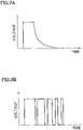
- FIGS.2A and 2B are diagrams for explaining the method of controlling the flashing of a vehicular lamp by the flashing indication part.
- the LED driving circuit 13 is capable of controlling the electric current of the light source 2
- the flashing indication part 11 supplies a variable voltage control signal indicating the electric current value corresponding to the desired luminous intensity of light to the electric current control terminal of the LED driving circuit 13, as shown in FIG.2A .
- the LED driving circuit 13 drives the light source 2 with the electric current having the magnitude corresponding to the control signal.
- the LED driving circuit 13 is capable of performing pulse width modulation (PWM) control of the light source 2, then the flashing indication part 11 supplies a variable pulse width control signal indicating the electric current value corresponding to the desired luminous intensity of light to the PWM control terminal of the LED driving circuit 13, as shown in FIG.2B . Thereby, the LED driving circuit 13 drives the light source 2 with the PWM controlled electric current having the magnitude corresponding to the control signal.
- PWM pulse width modulation
- FIG.3 is a diagram showing temporal changes of the luminous intensity of light emitted from the light source.
- the LED driving circuit 13 drives the light source 2 so that the light flashes periodically and repeatedly from the light source 2.
- FIG.3 shows one cycle of the luminous intensity change of the light flashing periodically and repeatedly. As shown in the figure, one cycle of the luminous intensity change includes four sections A, B, C, and D.
- Section A the luminous intensity substantially changes from 0% to 100% instantaneously from the starting point (at zero seconds) of the cycle.
- the time length of Section A corresponds to the rise time where the luminous intensity of light emitted from the light source 2 changes from 0% to 100% due to factors such as the time lag in the operation of the circuit which is inevitably generated.
- the time length required for Section A is the time corresponding to the rise time of the LEDs included in the light source 2 at the time of light emission and is therefore much shorter than the time length corresponding to one cycle.
- a range of 1 Hz to 2 Hz is assumed as the repetition frequency of light, and one cycle in this case becomes 0.5 seconds to 1 second (500 milliseconds to 1000 milliseconds).
- the time length of Section A is, for example, about several hundred microseconds to about 1 ms (millisecond). That is, the time length of Section A is set equal to or less than 1/500 of the time length of one cycle.
- luminous intensity 100% is defined as a state in which the luminous intensity set as the maximum value is being emitted during normal operation of flashing the light source 2, and for example refers to a state in which the rated maximum luminous intensity of each LED of the light source 2 is being emitted.
- luminous intensity 0% is defined as a state in which light is being turned off during normal flashing operation of the light source 2, and for example refers to a state in which each LED of the light source 2 is turned off or a state in which the luminous intensity is reduced to such an extent that human eyes can not perceive the lighting.
- Section B is the section following Section A, and is the section in which the state (luminous intensity 100%) is maintained after the luminous intensity of the light emitted from the light source reaches 100%.
- Section B starts from the end point of Section A and continues until time t1 which is a predetermined end point.
- the state of the luminous intensity 100% shall be deemed to be maintained.
- the state of the luminous intensity 100% shall be assumed, for example.
- Section C is the section following Section B and is the section in which the luminous intensity of the light emitted from the light source gradually decreases from 100% to 0%.
- Section C starts from time t1 which is the end point of Section B and continues until time t2 which is a predetermined end point.
- the time length of Section C is longer than the total time length of Sections A and B, and it is preferable to set the time length of Section C to be equal to or greater than three times of the total time length of Sections A and B.
- the change in luminous intensity forms a curved line where the decrease rate of the luminous intensity at the starting point is large and the decrease rate gradually decreases toward the end point of the section, but is not limited thereto.
- the change in luminous intensity may form a curved line where the decrease rate of the luminous intensity at the starting point is small and the decrease rate increases toward the end point of the section, or the change in luminous intensity may form a straight line where the decrease rate is constant.
- Section D is the section following Section C, and is the section in which the state where luminous intensity 0% is maintained after the light emitted from the light source reaches 0%. Section D starts from time t2 which is the end point of Section C and continues until the end point of one cycle. After the end point of Section D, Section A of the next cycle follows.
- the features of luminous intensity change in one cycle described above are as follows. Firstly, in Section A and Section B, utilizing the steepness of rise in light emission which is the intrinsic feature of each LED included in the light source 2, the luminous intensity is promptly set to the state of luminous intensity 100% and this state is maintained. Thereby, it is possible to obtain visibility equivalent to that of a turn signal lamp using the conventional LEDs. That is, it is possible to allow the observer to notice the flashing of the turn signal lamp sooner.
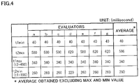
- FIG.4 is a diagram showing a sensory evaluation result regarding preferred values of the time length of each section of luminous intensity change.
- the preferred values for the time length of each section were evaluated by seven evaluators.
- the time length of each section was set variably and the minimum time unit was set to 10 ms.
- the maximum value and the minimum value among the sets of data obtained from each of the seven evaluators were excluded and five data were used to calculate the average.
- reference values at time t1 and time t2 in the luminous intensity change were set to 100 ms and 460 ms, respectively.
- the time length required for Section A was about 0.2 ms.
- one cycle was set to 667 ms which corresponds to a frequency of 1.5 Hz.
- Time tlmin is the result of evaluating the preferred minimum value at the end point time t1 of Section B (the second section).
- time t1 was decreased from 100 ms in increments of 10 ms, and the evaluation was carried out by seven evaluators.
- the evaluation criterion here is whether or not each evaluator felt that "the light is clearly dark or hard to notice" in Sections A and B.
- Time t2max shows the result of evaluating the preferred value as the maximum value of the end point time t2 in Section C (the third section) while time t1 is fixed at 100 ms.
- time t2 was increased from 460 ms in increments of 10 ms, and the evaluation was carried out by seven evaluators.
- the evaluation criteria here is whether or not each evaluator felt that "the flashing of light is clearly hard to recognize" in Section C.
- Time t1max is the result of evaluating the preferred maximum value at the end point time t1 of Section B while time t2 is fixed at 460 ms.
- time t1 was increased from 100 ms in increments of 10 ms, and the evaluation was carried out by seven evaluators.
- the evaluation criterion here is whether or not each evaluator felt that the light "does not seem to gradually disappear (gradual decrease of amount of light)" in Section C where the time length becomes relatively short as time t1 increases.
- the minimum value of time T2 of Section C be equal to or greater than three times the minimum value of the total time T1 of Sections A and B.
- Time t2min is the result of evaluating the preferred minimum value at the end point t2 of Section C while time t1 is fixed at 100 ms.
- time t2 was decreased from 460 ms in increments of 10 ms, and the evaluation was carried out by seven evaluators.
- the evaluation criterion here is whether or not each evaluator felt that the light "does not seem to gradually disappear (gradual decrease of amount of light)" in Section C where the time length becomes relatively short as time t2 decreases.
- the minimum value of time T2 of Section C be equal to or greater than four times the minimum value of the total time T1 of Sections A and B.
- the time length of one cycle was set to 667 ms (corresponding to a frequency of 1.5 Hz), but the time length of one cycle can be set ranging from 500 ms (corresponding to a frequency of 2 Hz) to 1000 ms (corresponding to a frequency of 1 Hz) where the above-stated preferred values remain effective. This is because even when the time length of one cycle changes, the time corresponding to the difference between the time length of one cycle and the total time (T1+T2) of Sections A to C can be set as the time length of time T3 of Section D (the fourth section).
- the luminous intensity steeply rises and is kept at the maximum value for a certain period of time thereafter, thereby improving the visibility for the observer. Further, thereafter, the luminous intensity gradually decreases within a certain period of time to reach the minimum value and is kept at the minimum value thereafter, thereby alleviating a sense of discomfort felt by the observer. Therefore, during light emission of vehicular lamps using LEDs or the like, improved visibility and alleviation of discomfort can both be achieved.
Landscapes
- Engineering & Computer Science (AREA)
- Mechanical Engineering (AREA)
- Lighting Device Outwards From Vehicle And Optical Signal (AREA)
Description
- The present invention relates to a technique for controlling the flashing of vehicular lamps used for applications such as turn signal lamps.
- A prior art of vehicular lamps used as turn signal lamps (winkers) is disclosed in, for example,
JP 2014-139941 A - Now, since a semiconductor light emitting device such as a LED inherently has a steep luminance changing characteristics, it is conceivable that this characteristics can contribute to visibility improvement when used as a turn signal or the like if it is used to its advantage.
- However, since the prior art disclosed in
JP 2014-139941 A - In a specific aspect, it is an object of the present invention to provide a technique capable of achieving both improved visibility and alleviation of discomfort during light emission of vehicular lamps using LEDs or the like.
-
EP 1 594 346 A2 -
JP 2007-287476 A - A lighting control apparatus according to one embodiment of the present invention is provided as set forth in
claim 1. Also provided is a vehicular lamp system as set forth in claim 4. Preferred embodiments of the present invention may be gathered from the dependent claims. - According to the configuration as stated above, during light emission of vehicular lamps using LEDs or the like, improved visibility and alleviation of discomfort can both be achieved.
-
-
FIG.1 is a diagram showing a configuration of a vehicular lamp system according to one embodiment. -
FIGS.2A and 2B are diagrams for explaining the method of controlling the flashing of of a vehicular lamp by the flashing indication part. -
FIG.3 is a diagram showing temporal changes of the luminous intensity of light emitted from the light source. -
FIG.4 is a diagram showing a sensory evaluation result regarding preferred values of the time length of each section of luminous intensity change. -
FIG.1 is a diagram showing a configuration of a vehicular lamp system according to one embodiment. The illustrated vehicular lamp system is used as a turn signal lamp (a turn lamp) of a vehicle, and is configured to include alighting control device 1 and a light source 2 that is subjected to lighting control by thelighting control device 1. - The
lighting control device 1 is configured to include acontrol part 10, aLED driving circuit 13, aregulator 14, an inputvoltage detecting part 15 , aprotection circuit 16, and a voltage conversion part 17 (which are abbreviated asCTRL PART 10,LED DRV CCT 13, REG 14, V-INDET PART 15, PCCT 16, V-CNV PART 17 inFIG.1 , respectively). Further, the light source 2 is configured to include one or more LEDs (semiconductor light emitting devices). - The
control part 10 is realized, for example, by a microcomputer executing a predetermined operation program, and it controls the overall operation of thelighting control device 1. Thecontrol part 10 includes aflashing indication part 11 and adisconnection detecting part 12 as function blocks (which are abbreviated as FL INDNPART 11, DC DETPART 12 inFIG.1 , respectively). - The
flashing indication part 11 outputs a control signal to theLED driving circuit 13 for controlling the flashing state of the light source 2. Specifically, for example, in a case where theLED driving circuit 13 controls the light intensity of the light source 2 according to the magnitude of the electric current, theflashing indication part 11 outputs a control signal indicating the electric current corresponding to the desired light intensity. - The
disconnection detecting part 12 detects disconnection of the circuit of the light source 2 if disconnection occurs, and outputs a disconnection detection signal to theflashing indication part 11. Upon receiving the disconnection detection signal, theflashing indication part 11 outputs a control signal to theLED driving circuit 13 in order to stop the power supply to the light source 2, for example. - The
LED driving circuit 13 supplies driving power to the light source 2 in order to flash the respective LEDs of the light source 2 based on the control signal outputted from theflashing indication part 11 using power (for example, power supplied from the vehicle battery) supplied via the highpotential terminal 30 and thereference potential terminal 31. - The
regulator 14 converts the voltage supplied via the highpotential terminal 30 and the referencepotential terminal 31 into a low potential voltage (for example, +5V) suitable for the operation of thecontrol part 10 and supplies thereto. Theregulator 14 incorporates a watchdog timer for monitoring abnormal operation of thecontrol part 10. - The input
voltage detecting part 15 detects the voltage and outputs a detection signal to the control part10 when the voltage supplied via the highpotential terminal 30 and the referencepotential terminal 31 falls below a predetermined threshold. - The
protection circuit 16 is connected to the highpotential terminal 30 and the referencepotential terminal 31 to protect the light source 2 when the light source 2 is reversely connected or to prevent surge voltage from flowing into thelighting control device 1 or the light source 2. - The voltage conversion part 17 converts the voltage of the disconnection detection signal into a predetermined value and outputs the voltage to
terminal 32 when the disconnection detection signal is outputted from thedisconnection detecting part 12. The disconnection detection signal outputted to theterminal 32 is used, for example, to turn on a warning light provided on the instrument panel of the vehicle. -
FIGS.2A and 2B are diagrams for explaining the method of controlling the flashing of a vehicular lamp by the flashing indication part. For example, if theLED driving circuit 13 is capable of controlling the electric current of the light source 2, then theflashing indication part 11 supplies a variable voltage control signal indicating the electric current value corresponding to the desired luminous intensity of light to the electric current control terminal of theLED driving circuit 13, as shown inFIG.2A . Thereby, theLED driving circuit 13 drives the light source 2 with the electric current having the magnitude corresponding to the control signal. On the other hand, for example, if theLED driving circuit 13 is capable of performing pulse width modulation (PWM) control of the light source 2, then theflashing indication part 11 supplies a variable pulse width control signal indicating the electric current value corresponding to the desired luminous intensity of light to the PWM control terminal of theLED driving circuit 13, as shown inFIG.2B . Thereby, theLED driving circuit 13 drives the light source 2 with the PWM controlled electric current having the magnitude corresponding to the control signal. -
FIG.3 is a diagram showing temporal changes of the luminous intensity of light emitted from the light source. In the present embodiment, theLED driving circuit 13 drives the light source 2 so that the light flashes periodically and repeatedly from the light source 2. AndFIG.3 shows one cycle of the luminous intensity change of the light flashing periodically and repeatedly. As shown in the figure, one cycle of the luminous intensity change includes four sections A, B, C, and D. - In Section A, the luminous intensity substantially changes from 0% to 100% instantaneously from the starting point (at zero seconds) of the cycle. Specifically, the time length of Section A corresponds to the rise time where the luminous intensity of light emitted from the light source 2 changes from 0% to 100% due to factors such as the time lag in the operation of the circuit which is inevitably generated.
- The time length required for Section A is the time corresponding to the rise time of the LEDs included in the light source 2 at the time of light emission and is therefore much shorter than the time length corresponding to one cycle. In the present embodiment, for example, a range of 1 Hz to 2 Hz is assumed as the repetition frequency of light, and one cycle in this case becomes 0.5 seconds to 1 second (500 milliseconds to 1000 milliseconds). On the other hand, the time length of Section A is, for example, about several hundred microseconds to about 1 ms (millisecond). That is, the time length of Section A is set equal to or less than 1/500 of the time length of one cycle.
- Herein, in this specification, "
luminous intensity 100%" is defined as a state in which the luminous intensity set as the maximum value is being emitted during normal operation of flashing the light source 2, and for example refers to a state in which the rated maximum luminous intensity of each LED of the light source 2 is being emitted. Also, in this specification, "luminous intensity 0%" is defined as a state in which light is being turned off during normal flashing operation of the light source 2, and for example refers to a state in which each LED of the light source 2 is turned off or a state in which the luminous intensity is reduced to such an extent that human eyes can not perceive the lighting. - Section B is the section following Section A, and is the section in which the state (
luminous intensity 100%) is maintained after the luminous intensity of the light emitted from the light source reaches 100%. Section B starts from the end point of Section A and continues until time t1 which is a predetermined end point. Here, although it is possible that the luminous intensity actually increases or decreases due to an increase or decrease in the power supply, even if such intrinsically unintended increase or decrease in luminous intensity occurs, the state of theluminous intensity 100% shall be deemed to be maintained. Specifically, when the luminous intensity is maintained within the range of ±10% on the basis of the maximum value of the luminous intensity set at the time during which the light source 2 is flashing, the state of theluminous intensity 100% shall be assumed, for example. - Section C is the section following Section B and is the section in which the luminous intensity of the light emitted from the light source gradually decreases from 100% to 0%. Section C starts from time t1 which is the end point of Section B and continues until time t2 which is a predetermined end point. As shown in the figure, it is preferable that the time length of Section C is longer than the total time length of Sections A and B, and it is preferable to set the time length of Section C to be equal to or greater than three times of the total time length of Sections A and B. Here, in the example shown in the figure, in Section C, the change in luminous intensity forms a curved line where the decrease rate of the luminous intensity at the starting point is large and the decrease rate gradually decreases toward the end point of the section, but is not limited thereto. For example, the change in luminous intensity may form a curved line where the decrease rate of the luminous intensity at the starting point is small and the decrease rate increases toward the end point of the section, or the change in luminous intensity may form a straight line where the decrease rate is constant.
- Section D is the section following Section C, and is the section in which the state where
luminous intensity 0% is maintained after the light emitted from the light source reaches 0%. Section D starts from time t2 which is the end point of Section C and continues until the end point of one cycle. After the end point of Section D, Section A of the next cycle follows. - In the vehicular lamp system of the present embodiment, the features of luminous intensity change in one cycle described above are as follows. Firstly, in Section A and Section B, utilizing the steepness of rise in light emission which is the intrinsic feature of each LED included in the light source 2, the luminous intensity is promptly set to the state of
luminous intensity 100% and this state is maintained. Thereby, it is possible to obtain visibility equivalent to that of a turn signal lamp using the conventional LEDs. That is, it is possible to allow the observer to notice the flashing of the turn signal lamp sooner. - Here, in a turn signal lamp that drives LEDs by using a simple rectangular wave as a driving method, since the state of
luminous intensity 100% continues from the turn-on time till the turn-off time, the total amount of light within one cycle (the integrated value of the amount of light) becomes large which makes the observer feel a strong glare when viewing the lamp. On the other hand, in Section C, since the luminous intensity is gradually reduced from 100% to 0%, the glare is reduced. Furthermore, since Section D maintains the luminous intensity in the 0% state, Section A in the following cycle (the section where the lamp is turned on instantaneously) becomes more distinguishable and the flashing becomes easier to recognize. Thus, it is possible to realize an eye friendly flashing state for the observer. - Further, when viewing Sections A to D as a whole, since the luminous intensity gradually decreases over a relatively long time after the luminous intensity steeply rises, unlike the conventional change in the luminous intensity of the turn signal lamp using LEDs, a new flashing light emission expression which is different from the change in luminous intensity of a turn signal lamp using light bulbs or a turn signal lamp imitating the light bulbs is realized.
-
FIG.4 is a diagram showing a sensory evaluation result regarding preferred values of the time length of each section of luminous intensity change. Here, the preferred values for the time length of each section were evaluated by seven evaluators. In the evaluation, the time length of each section was set variably and the minimum time unit was set to 10 ms. In addition, the maximum value and the minimum value among the sets of data obtained from each of the seven evaluators were excluded and five data were used to calculate the average. Also, reference values at time t1 and time t2 in the luminous intensity change were set to 100 ms and 460 ms, respectively. Further, the time length required for Section A was about 0.2 ms. Further, in the following evaluation, one cycle was set to 667 ms which corresponds to a frequency of 1.5 Hz. - Time tlmin is the result of evaluating the preferred minimum value at the end point time t1 of Section B (the second section). Here, time t1 was decreased from 100 ms in increments of 10 ms, and the evaluation was carried out by seven evaluators. The evaluation criterion here is whether or not each evaluator felt that "the light is clearly dark or hard to notice" in Sections A and B. When the evaluation results of these evaluators were averaged, the value of time tlmin=40 ms was obtained. From this result, it is understood that the preferred minimum value of the total time T1 of Sections A and B which is from
time 0 to time t1 is 40 ms. - Time t2max shows the result of evaluating the preferred value as the maximum value of the end point time t2 in Section C (the third section) while time t1 is fixed at 100 ms. Here, time t2 was increased from 460 ms in increments of 10 ms, and the evaluation was carried out by seven evaluators. The evaluation criteria here is whether or not each evaluator felt that "the flashing of light is clearly hard to recognize" in Section C. When the evaluation results of these evaluators were averaged, a value of time t2max=596 ms was obtained. From this result, it is understood that the preferred maximum value of time T2 in Section C which is from time t1 to time t2 is 496 ms (= 596 ms - 100 ms).
- Time t1max is the result of evaluating the preferred maximum value at the end point time t1 of Section B while time t2 is fixed at 460 ms. Here, time t1 was increased from 100 ms in increments of 10 ms, and the evaluation was carried out by seven evaluators. The evaluation criterion here is whether or not each evaluator felt that the light "does not seem to gradually disappear (gradual decrease of amount of light)" in Section C where the time length becomes relatively short as time t1 increases. When the evaluation results of these evaluators were averaged, a value of time tlmax=340 ms was obtained. From this result, it is understood that the preferred minimum value of time T2 in Section C which is from time t1 to time t2 is 120 ms (=460 ms - 340 ms). In other words, from this result, it is preferable that the minimum value of time T2 of Section C be equal to or greater than three times the minimum value of the total time T1 of Sections A and B.
- Time t2min is the result of evaluating the preferred minimum value at the end point t2 of Section C while time t1 is fixed at 100 ms. Here, time t2 was decreased from 460 ms in increments of 10 ms, and the evaluation was carried out by seven evaluators. The evaluation criterion here is whether or not each evaluator felt that the light "does not seem to gradually disappear (gradual decrease of amount of light)" in Section C where the time length becomes relatively short as time t2 decreases. When the evaluation results of these evaluators were averaged, a value of time t2min=260 ms was obtained. From this result, it is understood that the preferred minimum value of time T2 in Section C which is from time t1 to time t2 is 160 ms (=260 ms - 100 ms). In other words, from this result, it is preferable that the minimum value of time T2 of Section C be equal to or greater than four times the minimum value of the total time T1 of Sections A and B.
- Here, in the above evaluation, the time length of one cycle was set to 667 ms (corresponding to a frequency of 1.5 Hz), but the time length of one cycle can be set ranging from 500 ms (corresponding to a frequency of 2 Hz) to 1000 ms (corresponding to a frequency of 1 Hz) where the above-stated preferred values remain effective. This is because even when the time length of one cycle changes, the time corresponding to the difference between the time length of one cycle and the total time (T1+T2) of Sections A to C can be set as the time length of time T3 of Section D (the fourth section).
- According to the embodiment as described above, the luminous intensity steeply rises and is kept at the maximum value for a certain period of time thereafter, thereby improving the visibility for the observer. Further, thereafter, the luminous intensity gradually decreases within a certain period of time to reach the minimum value and is kept at the minimum value thereafter, thereby alleviating a sense of discomfort felt by the observer. Therefore, during light emission of vehicular lamps using LEDs or the like, improved visibility and alleviation of discomfort can both be achieved.
- It should be noted that this invention is not limited to the subject matter of the foregoing embodiment, and can be implemented by being variously modified within the scope of the present invention as defined by the appended claims. For example, in the above-described embodiment, a turn signal lamp is disclosed as an example of a vehicular lamp, but the scope of the present invention is not limited to such application.
Claims (4)
- A lighting control apparatus (1) for a vehicular lamp for controlling the flashing of a light source (2) used as a vehicular lamp having a semiconductor light emitting device comprising:a control part (10) for generating and outputting a control signal indicating luminous intensity of light emitted from the light source (2) anda light source driving part (13) for driving the light source (2) based on the control signal provided from the control part (10),wherein the light source driving part (13) is adapted to drive the light source (2) to emit light such that the light repeats a predetermined luminous intensity change pattern at a predetermined cycle,wherein the predetermined luminous intensity change pattern comprises:(i) a first section (A) where the luminous intensity is increased instantaneously from a lowest value to a highest value,(ii) a second section (B) following the first section (A) where the luminous intensity is maintained at the highest value,(iii) a third section (C) following the second section (B) where the luminous intensity is gradually decreased from the highest value to the lowest value, and(iv) a fourth section (D) following the third section (C) where the luminous intensity is maintained at the lowest value,wherein, in the first section (A), the luminous intensity changes from the lowest value to the highest value in the length of time equal to or less than 1/500 of the time length of the predetermined cycle,wherein the total length of time of the first section (A) and the second section (B) is set equal to or greater than 40 milliseconds. andwherein the length of time of the third section (C) is set equal to or greater than 120 milliseconds.
- The lighting control apparatus for a vehicular lamp according to claim 1,
wherein the predetermined cycle is set between 0.5 seconds and 1 second. - The lighting control apparatus for a vehicular lamp according to claim 1 or claim 2,
wherein, in the first section (A), the luminous intensity changes from the lowest value to the highest value in the length of time equal to or less than one millisecond. - A vehicular lamp system comprising:the lighting control apparatus (1) according to any one of the preceding claims, anda light source (2) controlled by the lighting control apparatus (1).
Applications Claiming Priority (2)
| Application Number | Priority Date | Filing Date | Title |
|---|---|---|---|
| JP2016118567A JP6803687B2 (en) | 2016-06-15 | 2016-06-15 | Lighting control device for vehicle lamps, vehicle lamp system |
| PCT/JP2017/020663 WO2017217260A1 (en) | 2016-06-15 | 2017-06-02 | Vehicle lamp lighting control device and vehicle lamp system |
Publications (3)
| Publication Number | Publication Date |
|---|---|
| EP3473494A1 EP3473494A1 (en) | 2019-04-24 |
| EP3473494A4 EP3473494A4 (en) | 2019-11-06 |
| EP3473494B1 true EP3473494B1 (en) | 2022-08-10 |
Family
ID=60663235
Family Applications (1)
| Application Number | Title | Priority Date | Filing Date |
|---|---|---|---|
| EP17813162.9A Active EP3473494B1 (en) | 2016-06-15 | 2017-06-02 | Vehicle lamp lighting control device and vehicle lamp system |
Country Status (5)
| Country | Link |
|---|---|
| US (1) | US10688917B2 (en) |
| EP (1) | EP3473494B1 (en) |
| JP (1) | JP6803687B2 (en) |
| CN (1) | CN109311418B (en) |
| WO (1) | WO2017217260A1 (en) |
Families Citing this family (6)
| Publication number | Priority date | Publication date | Assignee | Title |
|---|---|---|---|---|
| JP6803771B2 (en) * | 2017-02-27 | 2020-12-23 | スタンレー電気株式会社 | Lighting control device for vehicle lamps, vehicle lamp system |
| CN110985906A (en) * | 2019-11-19 | 2020-04-10 | 上海安珂麟汽车科技有限公司 | Installation process of automobile tail lamp |
| WO2022137995A1 (en) * | 2020-12-25 | 2022-06-30 | 株式会社小糸製作所 | Light irradiation system and lighting unit |
| JP7488841B2 (en) * | 2022-02-25 | 2024-05-22 | 株式会社パトライト | Diffused warning light system and vehicle equipped with same |
| CN115002983B (en) * | 2022-07-15 | 2023-02-03 | 深圳市爱图仕影像器材有限公司 | Lighting lamp, control method and device thereof, and computer-readable storage medium |
| CN120018341B (en) * | 2025-03-06 | 2025-12-02 | 深圳市文菲科技有限公司 | LED Vehicle Lighting Operation Monitoring System and Method Based on Data Analysis |
Family Cites Families (7)
| Publication number | Priority date | Publication date | Assignee | Title |
|---|---|---|---|---|
| US7332877B2 (en) * | 2003-11-24 | 2008-02-19 | Glowleds, Inc. | Light controller |
| DE102004022718A1 (en) * | 2004-05-07 | 2005-11-24 | Hella Kgaa Hueck & Co. | Method for controlling a flashing light for motor vehicles |
| JP4627252B2 (en) * | 2005-11-25 | 2011-02-09 | スタンレー電気株式会社 | Lighting fixture |
| JP2007287476A (en) * | 2006-04-17 | 2007-11-01 | Ichikoh Ind Ltd | Vehicle lamp lighting circuit |
| JP4656439B2 (en) * | 2007-02-07 | 2011-03-23 | 株式会社デンソー | WINKER CONTROL DEVICE FOR VEHICLE |
| CN101772438B (en) | 2007-08-07 | 2012-10-24 | 罗姆股份有限公司 | Light source lighting or extinguishing control device |
| CN107960069B (en) * | 2015-04-17 | 2024-02-02 | 株式会社小糸制作所 | Vehicle lamps |
-
2016
- 2016-06-15 JP JP2016118567A patent/JP6803687B2/en active Active
-
2017
- 2017-06-02 US US16/310,720 patent/US10688917B2/en active Active
- 2017-06-02 EP EP17813162.9A patent/EP3473494B1/en active Active
- 2017-06-02 WO PCT/JP2017/020663 patent/WO2017217260A1/en not_active Ceased
- 2017-06-02 CN CN201780037088.6A patent/CN109311418B/en active Active
Also Published As
| Publication number | Publication date |
|---|---|
| WO2017217260A1 (en) | 2017-12-21 |
| JP6803687B2 (en) | 2020-12-23 |
| EP3473494A4 (en) | 2019-11-06 |
| US10688917B2 (en) | 2020-06-23 |
| CN109311418B (en) | 2022-09-13 |
| CN109311418A (en) | 2019-02-05 |
| US20190143887A1 (en) | 2019-05-16 |
| EP3473494A1 (en) | 2019-04-24 |
| JP2017222259A (en) | 2017-12-21 |
Similar Documents
| Publication | Publication Date | Title |
|---|---|---|
| EP3473494A1 (en) | Vehicle lamp lighting control device and vehicle lamp system | |
| JP6688008B2 (en) | Vehicle lighting | |
| JP6199721B2 (en) | Vehicle lighting | |
| EP3587185B1 (en) | Vehicle lamp lighting control device and vehicle lamp system | |
| JP5501134B2 (en) | LED lighting device | |
| JP6278298B2 (en) | Lighting device, headlight device using the same, and vehicle | |
| JP6865633B2 (en) | Vehicle lighting | |
| JP2017021953A (en) | LIGHTING DEVICE, VEHICLE LIGHTING DEVICE, AND VEHICLE USING THE SAME | |
| JP6302706B2 (en) | VEHICLE LIGHT AND DRIVE DEVICE THEREOF | |
| JP5588184B2 (en) | LED lighting device, lighting device, and vehicle | |
| US8278826B2 (en) | Multimode controller for LED light sources | |
| JP6151523B2 (en) | Drive circuit, vehicle lamp | |
| JP2015154704A (en) | Vehicle lamp and driving device therefor | |
| JP2018118556A (en) | Lighting circuit and vehicle lamp | |
| JP7037036B2 (en) | Light emitting diode drive device and lighting for plant cultivation using it | |
| JP2022191082A (en) | Lighting control apparatus, lighting control method, and illuminating device | |
| JP2012221772A (en) | Luminaire | |
| KR102373176B1 (en) | Apparatus for driving led for vehicle | |
| JP6767127B2 (en) | Dimming control device for vehicles | |
| CN101688661B (en) | Flashing lights for alarm devices | |
| KR101608318B1 (en) | Warning light apparatus and operating method thereof | |
| JP6459884B2 (en) | Lighting device | |
| JP2016100116A (en) | Led illumination device, led lighting device and led lighting control method | |
| JP2025072837A (en) | Vehicle lighting system | |
| KR102361145B1 (en) | Apparatus for controlling lamp of vehicle |
Legal Events
| Date | Code | Title | Description |
|---|---|---|---|
| STAA | Information on the status of an ep patent application or granted ep patent |
Free format text: STATUS: THE INTERNATIONAL PUBLICATION HAS BEEN MADE |
|
| PUAI | Public reference made under article 153(3) epc to a published international application that has entered the european phase |
Free format text: ORIGINAL CODE: 0009012 |
|
| STAA | Information on the status of an ep patent application or granted ep patent |
Free format text: STATUS: REQUEST FOR EXAMINATION WAS MADE |
|
| 17P | Request for examination filed |
Effective date: 20181214 |
|
| AK | Designated contracting states |
Kind code of ref document: A1 Designated state(s): AL AT BE BG CH CY CZ DE DK EE ES FI FR GB GR HR HU IE IS IT LI LT LU LV MC MK MT NL NO PL PT RO RS SE SI SK SM TR |
|
| AX | Request for extension of the european patent |
Extension state: BA ME |
|
| DAV | Request for validation of the european patent (deleted) | ||
| DAX | Request for extension of the european patent (deleted) | ||
| A4 | Supplementary search report drawn up and despatched |
Effective date: 20191008 |
|
| RIC1 | Information provided on ipc code assigned before grant |
Ipc: B60Q 1/34 20060101AFI20191001BHEP Ipc: H05B 33/08 20060101ALI20191001BHEP Ipc: H05B 37/02 20060101ALI20191001BHEP |
|
| REG | Reference to a national code |
Ref country code: DE Ref legal event code: R079 Ref document number: 602017060548 Country of ref document: DE Free format text: PREVIOUS MAIN CLASS: B60Q0001340000 Ipc: H05B0045100000 |
|
| GRAP | Despatch of communication of intention to grant a patent |
Free format text: ORIGINAL CODE: EPIDOSNIGR1 |
|
| STAA | Information on the status of an ep patent application or granted ep patent |
Free format text: STATUS: GRANT OF PATENT IS INTENDED |
|
| RIC1 | Information provided on ipc code assigned before grant |
Ipc: H05B 45/325 20200101ALN20220210BHEP Ipc: B60Q 1/34 20060101ALI20220210BHEP Ipc: H05B 47/16 20200101ALI20220210BHEP Ipc: H05B 45/10 20200101AFI20220210BHEP |
|
| INTG | Intention to grant announced |
Effective date: 20220225 |
|
| GRAS | Grant fee paid |
Free format text: ORIGINAL CODE: EPIDOSNIGR3 |
|
| GRAA | (expected) grant |
Free format text: ORIGINAL CODE: 0009210 |
|
| STAA | Information on the status of an ep patent application or granted ep patent |
Free format text: STATUS: THE PATENT HAS BEEN GRANTED |
|
| AK | Designated contracting states |
Kind code of ref document: B1 Designated state(s): AL AT BE BG CH CY CZ DE DK EE ES FI FR GB GR HR HU IE IS IT LI LT LU LV MC MK MT NL NO PL PT RO RS SE SI SK SM TR |
|
| REG | Reference to a national code |
Ref country code: AT Ref legal event code: REF Ref document number: 1511517 Country of ref document: AT Kind code of ref document: T Effective date: 20220815 Ref country code: CH Ref legal event code: EP |
|
| REG | Reference to a national code |
Ref country code: DE Ref legal event code: R096 Ref document number: 602017060548 Country of ref document: DE |
|
| REG | Reference to a national code |
Ref country code: IE Ref legal event code: FG4D |
|
| REG | Reference to a national code |
Ref country code: NL Ref legal event code: MP Effective date: 20220810 |
|
| REG | Reference to a national code |
Ref country code: LT Ref legal event code: MG9D |
|
| PG25 | Lapsed in a contracting state [announced via postgrant information from national office to epo] |
Ref country code: SE Free format text: LAPSE BECAUSE OF FAILURE TO SUBMIT A TRANSLATION OF THE DESCRIPTION OR TO PAY THE FEE WITHIN THE PRESCRIBED TIME-LIMIT Effective date: 20220810 Ref country code: RS Free format text: LAPSE BECAUSE OF FAILURE TO SUBMIT A TRANSLATION OF THE DESCRIPTION OR TO PAY THE FEE WITHIN THE PRESCRIBED TIME-LIMIT Effective date: 20220810 Ref country code: PT Free format text: LAPSE BECAUSE OF FAILURE TO SUBMIT A TRANSLATION OF THE DESCRIPTION OR TO PAY THE FEE WITHIN THE PRESCRIBED TIME-LIMIT Effective date: 20221212 Ref country code: NO Free format text: LAPSE BECAUSE OF FAILURE TO SUBMIT A TRANSLATION OF THE DESCRIPTION OR TO PAY THE FEE WITHIN THE PRESCRIBED TIME-LIMIT Effective date: 20221110 Ref country code: NL Free format text: LAPSE BECAUSE OF FAILURE TO SUBMIT A TRANSLATION OF THE DESCRIPTION OR TO PAY THE FEE WITHIN THE PRESCRIBED TIME-LIMIT Effective date: 20220810 Ref country code: LV Free format text: LAPSE BECAUSE OF FAILURE TO SUBMIT A TRANSLATION OF THE DESCRIPTION OR TO PAY THE FEE WITHIN THE PRESCRIBED TIME-LIMIT Effective date: 20220810 Ref country code: LT Free format text: LAPSE BECAUSE OF FAILURE TO SUBMIT A TRANSLATION OF THE DESCRIPTION OR TO PAY THE FEE WITHIN THE PRESCRIBED TIME-LIMIT Effective date: 20220810 Ref country code: FI Free format text: LAPSE BECAUSE OF FAILURE TO SUBMIT A TRANSLATION OF THE DESCRIPTION OR TO PAY THE FEE WITHIN THE PRESCRIBED TIME-LIMIT Effective date: 20220810 |
|
| REG | Reference to a national code |
Ref country code: AT Ref legal event code: MK05 Ref document number: 1511517 Country of ref document: AT Kind code of ref document: T Effective date: 20220810 |
|
| PG25 | Lapsed in a contracting state [announced via postgrant information from national office to epo] |
Ref country code: PL Free format text: LAPSE BECAUSE OF FAILURE TO SUBMIT A TRANSLATION OF THE DESCRIPTION OR TO PAY THE FEE WITHIN THE PRESCRIBED TIME-LIMIT Effective date: 20220810 Ref country code: IS Free format text: LAPSE BECAUSE OF FAILURE TO SUBMIT A TRANSLATION OF THE DESCRIPTION OR TO PAY THE FEE WITHIN THE PRESCRIBED TIME-LIMIT Effective date: 20221210 Ref country code: HR Free format text: LAPSE BECAUSE OF FAILURE TO SUBMIT A TRANSLATION OF THE DESCRIPTION OR TO PAY THE FEE WITHIN THE PRESCRIBED TIME-LIMIT Effective date: 20220810 Ref country code: GR Free format text: LAPSE BECAUSE OF FAILURE TO SUBMIT A TRANSLATION OF THE DESCRIPTION OR TO PAY THE FEE WITHIN THE PRESCRIBED TIME-LIMIT Effective date: 20221111 |
|
| PG25 | Lapsed in a contracting state [announced via postgrant information from national office to epo] |
Ref country code: SM Free format text: LAPSE BECAUSE OF FAILURE TO SUBMIT A TRANSLATION OF THE DESCRIPTION OR TO PAY THE FEE WITHIN THE PRESCRIBED TIME-LIMIT Effective date: 20220810 Ref country code: RO Free format text: LAPSE BECAUSE OF FAILURE TO SUBMIT A TRANSLATION OF THE DESCRIPTION OR TO PAY THE FEE WITHIN THE PRESCRIBED TIME-LIMIT Effective date: 20220810 Ref country code: ES Free format text: LAPSE BECAUSE OF FAILURE TO SUBMIT A TRANSLATION OF THE DESCRIPTION OR TO PAY THE FEE WITHIN THE PRESCRIBED TIME-LIMIT Effective date: 20220810 Ref country code: DK Free format text: LAPSE BECAUSE OF FAILURE TO SUBMIT A TRANSLATION OF THE DESCRIPTION OR TO PAY THE FEE WITHIN THE PRESCRIBED TIME-LIMIT Effective date: 20220810 Ref country code: CZ Free format text: LAPSE BECAUSE OF FAILURE TO SUBMIT A TRANSLATION OF THE DESCRIPTION OR TO PAY THE FEE WITHIN THE PRESCRIBED TIME-LIMIT Effective date: 20220810 Ref country code: AT Free format text: LAPSE BECAUSE OF FAILURE TO SUBMIT A TRANSLATION OF THE DESCRIPTION OR TO PAY THE FEE WITHIN THE PRESCRIBED TIME-LIMIT Effective date: 20220810 |
|
| REG | Reference to a national code |
Ref country code: DE Ref legal event code: R097 Ref document number: 602017060548 Country of ref document: DE |
|
| PG25 | Lapsed in a contracting state [announced via postgrant information from national office to epo] |
Ref country code: SK Free format text: LAPSE BECAUSE OF FAILURE TO SUBMIT A TRANSLATION OF THE DESCRIPTION OR TO PAY THE FEE WITHIN THE PRESCRIBED TIME-LIMIT Effective date: 20220810 Ref country code: EE Free format text: LAPSE BECAUSE OF FAILURE TO SUBMIT A TRANSLATION OF THE DESCRIPTION OR TO PAY THE FEE WITHIN THE PRESCRIBED TIME-LIMIT Effective date: 20220810 |
|
| PLBE | No opposition filed within time limit |
Free format text: ORIGINAL CODE: 0009261 |
|
| STAA | Information on the status of an ep patent application or granted ep patent |
Free format text: STATUS: NO OPPOSITION FILED WITHIN TIME LIMIT |
|
| PG25 | Lapsed in a contracting state [announced via postgrant information from national office to epo] |
Ref country code: AL Free format text: LAPSE BECAUSE OF FAILURE TO SUBMIT A TRANSLATION OF THE DESCRIPTION OR TO PAY THE FEE WITHIN THE PRESCRIBED TIME-LIMIT Effective date: 20220810 |
|
| 26N | No opposition filed |
Effective date: 20230511 |
|
| PG25 | Lapsed in a contracting state [announced via postgrant information from national office to epo] |
Ref country code: SI Free format text: LAPSE BECAUSE OF FAILURE TO SUBMIT A TRANSLATION OF THE DESCRIPTION OR TO PAY THE FEE WITHIN THE PRESCRIBED TIME-LIMIT Effective date: 20220810 |
|
| PG25 | Lapsed in a contracting state [announced via postgrant information from national office to epo] |
Ref country code: MC Free format text: LAPSE BECAUSE OF FAILURE TO SUBMIT A TRANSLATION OF THE DESCRIPTION OR TO PAY THE FEE WITHIN THE PRESCRIBED TIME-LIMIT Effective date: 20220810 |
|
| PG25 | Lapsed in a contracting state [announced via postgrant information from national office to epo] |
Ref country code: MC Free format text: LAPSE BECAUSE OF FAILURE TO SUBMIT A TRANSLATION OF THE DESCRIPTION OR TO PAY THE FEE WITHIN THE PRESCRIBED TIME-LIMIT Effective date: 20220810 |
|
| REG | Reference to a national code |
Ref country code: CH Ref legal event code: PL |
|
| REG | Reference to a national code |
Ref country code: BE Ref legal event code: MM Effective date: 20230630 |
|
| PG25 | Lapsed in a contracting state [announced via postgrant information from national office to epo] |
Ref country code: LU Free format text: LAPSE BECAUSE OF NON-PAYMENT OF DUE FEES Effective date: 20230602 |
|
| REG | Reference to a national code |
Ref country code: IE Ref legal event code: MM4A |
|
| PG25 | Lapsed in a contracting state [announced via postgrant information from national office to epo] |
Ref country code: LU Free format text: LAPSE BECAUSE OF NON-PAYMENT OF DUE FEES Effective date: 20230602 |
|
| PG25 | Lapsed in a contracting state [announced via postgrant information from national office to epo] |
Ref country code: IE Free format text: LAPSE BECAUSE OF NON-PAYMENT OF DUE FEES Effective date: 20230602 |
|
| PG25 | Lapsed in a contracting state [announced via postgrant information from national office to epo] |
Ref country code: IE Free format text: LAPSE BECAUSE OF NON-PAYMENT OF DUE FEES Effective date: 20230602 Ref country code: CH Free format text: LAPSE BECAUSE OF NON-PAYMENT OF DUE FEES Effective date: 20230630 |
|
| PG25 | Lapsed in a contracting state [announced via postgrant information from national office to epo] |
Ref country code: IT Free format text: LAPSE BECAUSE OF FAILURE TO SUBMIT A TRANSLATION OF THE DESCRIPTION OR TO PAY THE FEE WITHIN THE PRESCRIBED TIME-LIMIT Effective date: 20220810 Ref country code: BE Free format text: LAPSE BECAUSE OF NON-PAYMENT OF DUE FEES Effective date: 20230630 |
|
| PG25 | Lapsed in a contracting state [announced via postgrant information from national office to epo] |
Ref country code: BG Free format text: LAPSE BECAUSE OF FAILURE TO SUBMIT A TRANSLATION OF THE DESCRIPTION OR TO PAY THE FEE WITHIN THE PRESCRIBED TIME-LIMIT Effective date: 20220810 |
|
| PG25 | Lapsed in a contracting state [announced via postgrant information from national office to epo] |
Ref country code: BG Free format text: LAPSE BECAUSE OF FAILURE TO SUBMIT A TRANSLATION OF THE DESCRIPTION OR TO PAY THE FEE WITHIN THE PRESCRIBED TIME-LIMIT Effective date: 20220810 |
|
| PGFP | Annual fee paid to national office [announced via postgrant information from national office to epo] |
Ref country code: DE Payment date: 20250429 Year of fee payment: 9 |
|
| PGFP | Annual fee paid to national office [announced via postgrant information from national office to epo] |
Ref country code: GB Payment date: 20250501 Year of fee payment: 9 |
|
| PGFP | Annual fee paid to national office [announced via postgrant information from national office to epo] |
Ref country code: FR Payment date: 20250508 Year of fee payment: 9 |
|
| PG25 | Lapsed in a contracting state [announced via postgrant information from national office to epo] |
Ref country code: CY Free format text: LAPSE BECAUSE OF FAILURE TO SUBMIT A TRANSLATION OF THE DESCRIPTION OR TO PAY THE FEE WITHIN THE PRESCRIBED TIME-LIMIT; INVALID AB INITIO Effective date: 20170602 |
|
| PG25 | Lapsed in a contracting state [announced via postgrant information from national office to epo] |
Ref country code: HU Free format text: LAPSE BECAUSE OF FAILURE TO SUBMIT A TRANSLATION OF THE DESCRIPTION OR TO PAY THE FEE WITHIN THE PRESCRIBED TIME-LIMIT; INVALID AB INITIO Effective date: 20170602 |
|
| PG25 | Lapsed in a contracting state [announced via postgrant information from national office to epo] |
Ref country code: TR Free format text: LAPSE BECAUSE OF FAILURE TO SUBMIT A TRANSLATION OF THE DESCRIPTION OR TO PAY THE FEE WITHIN THE PRESCRIBED TIME-LIMIT Effective date: 20220810 |