EP3473481A1 - Fuel cell vehicle - Google Patents
Fuel cell vehicle Download PDFInfo
- Publication number
- EP3473481A1 EP3473481A1 EP18187357.1A EP18187357A EP3473481A1 EP 3473481 A1 EP3473481 A1 EP 3473481A1 EP 18187357 A EP18187357 A EP 18187357A EP 3473481 A1 EP3473481 A1 EP 3473481A1
- Authority
- EP
- European Patent Office
- Prior art keywords
- controller
- current value
- injector
- voltage
- electric power
- Prior art date
- Legal status (The legal status is an assumption and is not a legal conclusion. Google has not performed a legal analysis and makes no representation as to the accuracy of the status listed.)
- Granted
Links
Images


Classifications
-
- H—ELECTRICITY
- H01—ELECTRIC ELEMENTS
- H01M—PROCESSES OR MEANS, e.g. BATTERIES, FOR THE DIRECT CONVERSION OF CHEMICAL ENERGY INTO ELECTRICAL ENERGY
- H01M8/00—Fuel cells; Manufacture thereof
- H01M8/04—Auxiliary arrangements, e.g. for control of pressure or for circulation of fluids
- H01M8/04298—Processes for controlling fuel cells or fuel cell systems
- H01M8/04313—Processes for controlling fuel cells or fuel cell systems characterised by the detection or assessment of variables; characterised by the detection or assessment of failure or abnormal function
- H01M8/04537—Electric variables
- H01M8/04574—Current
- H01M8/04597—Current of auxiliary devices, e.g. batteries, capacitors
-
- B—PERFORMING OPERATIONS; TRANSPORTING
- B60—VEHICLES IN GENERAL
- B60L—PROPULSION OF ELECTRICALLY-PROPELLED VEHICLES; SUPPLYING ELECTRIC POWER FOR AUXILIARY EQUIPMENT OF ELECTRICALLY-PROPELLED VEHICLES; ELECTRODYNAMIC BRAKE SYSTEMS FOR VEHICLES IN GENERAL; MAGNETIC SUSPENSION OR LEVITATION FOR VEHICLES; MONITORING OPERATING VARIABLES OF ELECTRICALLY-PROPELLED VEHICLES; ELECTRIC SAFETY DEVICES FOR ELECTRICALLY-PROPELLED VEHICLES
- B60L1/00—Supplying electric power to auxiliary equipment of vehicles
-
- B—PERFORMING OPERATIONS; TRANSPORTING
- B60—VEHICLES IN GENERAL
- B60L—PROPULSION OF ELECTRICALLY-PROPELLED VEHICLES; SUPPLYING ELECTRIC POWER FOR AUXILIARY EQUIPMENT OF ELECTRICALLY-PROPELLED VEHICLES; ELECTRODYNAMIC BRAKE SYSTEMS FOR VEHICLES IN GENERAL; MAGNETIC SUSPENSION OR LEVITATION FOR VEHICLES; MONITORING OPERATING VARIABLES OF ELECTRICALLY-PROPELLED VEHICLES; ELECTRIC SAFETY DEVICES FOR ELECTRICALLY-PROPELLED VEHICLES
- B60L1/00—Supplying electric power to auxiliary equipment of vehicles
- B60L1/003—Supplying electric power to auxiliary equipment of vehicles to auxiliary motors, e.g. for pumps, compressors
-
- B—PERFORMING OPERATIONS; TRANSPORTING
- B60—VEHICLES IN GENERAL
- B60L—PROPULSION OF ELECTRICALLY-PROPELLED VEHICLES; SUPPLYING ELECTRIC POWER FOR AUXILIARY EQUIPMENT OF ELECTRICALLY-PROPELLED VEHICLES; ELECTRODYNAMIC BRAKE SYSTEMS FOR VEHICLES IN GENERAL; MAGNETIC SUSPENSION OR LEVITATION FOR VEHICLES; MONITORING OPERATING VARIABLES OF ELECTRICALLY-PROPELLED VEHICLES; ELECTRIC SAFETY DEVICES FOR ELECTRICALLY-PROPELLED VEHICLES
- B60L50/00—Electric propulsion with power supplied within the vehicle
- B60L50/50—Electric propulsion with power supplied within the vehicle using propulsion power supplied by batteries or fuel cells
- B60L50/70—Electric propulsion with power supplied within the vehicle using propulsion power supplied by batteries or fuel cells using power supplied by fuel cells
-
- B—PERFORMING OPERATIONS; TRANSPORTING
- B60—VEHICLES IN GENERAL
- B60L—PROPULSION OF ELECTRICALLY-PROPELLED VEHICLES; SUPPLYING ELECTRIC POWER FOR AUXILIARY EQUIPMENT OF ELECTRICALLY-PROPELLED VEHICLES; ELECTRODYNAMIC BRAKE SYSTEMS FOR VEHICLES IN GENERAL; MAGNETIC SUSPENSION OR LEVITATION FOR VEHICLES; MONITORING OPERATING VARIABLES OF ELECTRICALLY-PROPELLED VEHICLES; ELECTRIC SAFETY DEVICES FOR ELECTRICALLY-PROPELLED VEHICLES
- B60L50/00—Electric propulsion with power supplied within the vehicle
- B60L50/50—Electric propulsion with power supplied within the vehicle using propulsion power supplied by batteries or fuel cells
- B60L50/75—Electric propulsion with power supplied within the vehicle using propulsion power supplied by batteries or fuel cells using propulsion power supplied by both fuel cells and batteries
-
- B—PERFORMING OPERATIONS; TRANSPORTING
- B60—VEHICLES IN GENERAL
- B60L—PROPULSION OF ELECTRICALLY-PROPELLED VEHICLES; SUPPLYING ELECTRIC POWER FOR AUXILIARY EQUIPMENT OF ELECTRICALLY-PROPELLED VEHICLES; ELECTRODYNAMIC BRAKE SYSTEMS FOR VEHICLES IN GENERAL; MAGNETIC SUSPENSION OR LEVITATION FOR VEHICLES; MONITORING OPERATING VARIABLES OF ELECTRICALLY-PROPELLED VEHICLES; ELECTRIC SAFETY DEVICES FOR ELECTRICALLY-PROPELLED VEHICLES
- B60L58/00—Methods or circuit arrangements for monitoring or controlling batteries or fuel cells, specially adapted for electric vehicles
- B60L58/10—Methods or circuit arrangements for monitoring or controlling batteries or fuel cells, specially adapted for electric vehicles for monitoring or controlling batteries
- B60L58/18—Methods or circuit arrangements for monitoring or controlling batteries or fuel cells, specially adapted for electric vehicles for monitoring or controlling batteries of two or more battery modules
- B60L58/20—Methods or circuit arrangements for monitoring or controlling batteries or fuel cells, specially adapted for electric vehicles for monitoring or controlling batteries of two or more battery modules having different nominal voltages
-
- B—PERFORMING OPERATIONS; TRANSPORTING
- B60—VEHICLES IN GENERAL
- B60L—PROPULSION OF ELECTRICALLY-PROPELLED VEHICLES; SUPPLYING ELECTRIC POWER FOR AUXILIARY EQUIPMENT OF ELECTRICALLY-PROPELLED VEHICLES; ELECTRODYNAMIC BRAKE SYSTEMS FOR VEHICLES IN GENERAL; MAGNETIC SUSPENSION OR LEVITATION FOR VEHICLES; MONITORING OPERATING VARIABLES OF ELECTRICALLY-PROPELLED VEHICLES; ELECTRIC SAFETY DEVICES FOR ELECTRICALLY-PROPELLED VEHICLES
- B60L58/00—Methods or circuit arrangements for monitoring or controlling batteries or fuel cells, specially adapted for electric vehicles
- B60L58/30—Methods or circuit arrangements for monitoring or controlling batteries or fuel cells, specially adapted for electric vehicles for monitoring or controlling fuel cells
-
- B—PERFORMING OPERATIONS; TRANSPORTING
- B60—VEHICLES IN GENERAL
- B60L—PROPULSION OF ELECTRICALLY-PROPELLED VEHICLES; SUPPLYING ELECTRIC POWER FOR AUXILIARY EQUIPMENT OF ELECTRICALLY-PROPELLED VEHICLES; ELECTRODYNAMIC BRAKE SYSTEMS FOR VEHICLES IN GENERAL; MAGNETIC SUSPENSION OR LEVITATION FOR VEHICLES; MONITORING OPERATING VARIABLES OF ELECTRICALLY-PROPELLED VEHICLES; ELECTRIC SAFETY DEVICES FOR ELECTRICALLY-PROPELLED VEHICLES
- B60L58/00—Methods or circuit arrangements for monitoring or controlling batteries or fuel cells, specially adapted for electric vehicles
- B60L58/40—Methods or circuit arrangements for monitoring or controlling batteries or fuel cells, specially adapted for electric vehicles for controlling a combination of batteries and fuel cells
-
- H—ELECTRICITY
- H01—ELECTRIC ELEMENTS
- H01M—PROCESSES OR MEANS, e.g. BATTERIES, FOR THE DIRECT CONVERSION OF CHEMICAL ENERGY INTO ELECTRICAL ENERGY
- H01M8/00—Fuel cells; Manufacture thereof
- H01M8/04—Auxiliary arrangements, e.g. for control of pressure or for circulation of fluids
- H01M8/04082—Arrangements for control of reactant parameters, e.g. pressure or concentration
- H01M8/04089—Arrangements for control of reactant parameters, e.g. pressure or concentration of gaseous reactants
-
- H—ELECTRICITY
- H01—ELECTRIC ELEMENTS
- H01M—PROCESSES OR MEANS, e.g. BATTERIES, FOR THE DIRECT CONVERSION OF CHEMICAL ENERGY INTO ELECTRICAL ENERGY
- H01M8/00—Fuel cells; Manufacture thereof
- H01M8/04—Auxiliary arrangements, e.g. for control of pressure or for circulation of fluids
- H01M8/04223—Auxiliary arrangements, e.g. for control of pressure or for circulation of fluids during start-up or shut-down; Depolarisation or activation, e.g. purging; Means for short-circuiting defective fuel cells
- H01M8/04225—Auxiliary arrangements, e.g. for control of pressure or for circulation of fluids during start-up or shut-down; Depolarisation or activation, e.g. purging; Means for short-circuiting defective fuel cells during start-up
-
- H—ELECTRICITY
- H01—ELECTRIC ELEMENTS
- H01M—PROCESSES OR MEANS, e.g. BATTERIES, FOR THE DIRECT CONVERSION OF CHEMICAL ENERGY INTO ELECTRICAL ENERGY
- H01M8/00—Fuel cells; Manufacture thereof
- H01M8/04—Auxiliary arrangements, e.g. for control of pressure or for circulation of fluids
- H01M8/04298—Processes for controlling fuel cells or fuel cell systems
- H01M8/04313—Processes for controlling fuel cells or fuel cell systems characterised by the detection or assessment of variables; characterised by the detection or assessment of failure or abnormal function
- H01M8/0438—Pressure; Ambient pressure; Flow
- H01M8/04388—Pressure; Ambient pressure; Flow of anode reactants at the inlet or inside the fuel cell
-
- H—ELECTRICITY
- H01—ELECTRIC ELEMENTS
- H01M—PROCESSES OR MEANS, e.g. BATTERIES, FOR THE DIRECT CONVERSION OF CHEMICAL ENERGY INTO ELECTRICAL ENERGY
- H01M8/00—Fuel cells; Manufacture thereof
- H01M8/04—Auxiliary arrangements, e.g. for control of pressure or for circulation of fluids
- H01M8/04298—Processes for controlling fuel cells or fuel cell systems
- H01M8/04313—Processes for controlling fuel cells or fuel cell systems characterised by the detection or assessment of variables; characterised by the detection or assessment of failure or abnormal function
- H01M8/04537—Electric variables
- H01M8/04544—Voltage
- H01M8/04567—Voltage of auxiliary devices, e.g. batteries, capacitors
-
- H—ELECTRICITY
- H01—ELECTRIC ELEMENTS
- H01M—PROCESSES OR MEANS, e.g. BATTERIES, FOR THE DIRECT CONVERSION OF CHEMICAL ENERGY INTO ELECTRICAL ENERGY
- H01M8/00—Fuel cells; Manufacture thereof
- H01M8/04—Auxiliary arrangements, e.g. for control of pressure or for circulation of fluids
- H01M8/04298—Processes for controlling fuel cells or fuel cell systems
- H01M8/04694—Processes for controlling fuel cells or fuel cell systems characterised by variables to be controlled
- H01M8/04746—Pressure; Flow
- H01M8/04753—Pressure; Flow of fuel cell reactants
-
- H—ELECTRICITY
- H01—ELECTRIC ELEMENTS
- H01M—PROCESSES OR MEANS, e.g. BATTERIES, FOR THE DIRECT CONVERSION OF CHEMICAL ENERGY INTO ELECTRICAL ENERGY
- H01M8/00—Fuel cells; Manufacture thereof
- H01M8/04—Auxiliary arrangements, e.g. for control of pressure or for circulation of fluids
- H01M8/04298—Processes for controlling fuel cells or fuel cell systems
- H01M8/04694—Processes for controlling fuel cells or fuel cell systems characterised by variables to be controlled
- H01M8/04858—Electric variables
- H01M8/04895—Current
- H01M8/04917—Current of auxiliary devices, e.g. batteries, capacitors
-
- B—PERFORMING OPERATIONS; TRANSPORTING
- B60—VEHICLES IN GENERAL
- B60L—PROPULSION OF ELECTRICALLY-PROPELLED VEHICLES; SUPPLYING ELECTRIC POWER FOR AUXILIARY EQUIPMENT OF ELECTRICALLY-PROPELLED VEHICLES; ELECTRODYNAMIC BRAKE SYSTEMS FOR VEHICLES IN GENERAL; MAGNETIC SUSPENSION OR LEVITATION FOR VEHICLES; MONITORING OPERATING VARIABLES OF ELECTRICALLY-PROPELLED VEHICLES; ELECTRIC SAFETY DEVICES FOR ELECTRICALLY-PROPELLED VEHICLES
- B60L2210/00—Converter types
- B60L2210/10—DC to DC converters
-
- B—PERFORMING OPERATIONS; TRANSPORTING
- B60—VEHICLES IN GENERAL
- B60L—PROPULSION OF ELECTRICALLY-PROPELLED VEHICLES; SUPPLYING ELECTRIC POWER FOR AUXILIARY EQUIPMENT OF ELECTRICALLY-PROPELLED VEHICLES; ELECTRODYNAMIC BRAKE SYSTEMS FOR VEHICLES IN GENERAL; MAGNETIC SUSPENSION OR LEVITATION FOR VEHICLES; MONITORING OPERATING VARIABLES OF ELECTRICALLY-PROPELLED VEHICLES; ELECTRIC SAFETY DEVICES FOR ELECTRICALLY-PROPELLED VEHICLES
- B60L2210/00—Converter types
- B60L2210/10—DC to DC converters
- B60L2210/12—Buck converters
-
- B—PERFORMING OPERATIONS; TRANSPORTING
- B60—VEHICLES IN GENERAL
- B60L—PROPULSION OF ELECTRICALLY-PROPELLED VEHICLES; SUPPLYING ELECTRIC POWER FOR AUXILIARY EQUIPMENT OF ELECTRICALLY-PROPELLED VEHICLES; ELECTRODYNAMIC BRAKE SYSTEMS FOR VEHICLES IN GENERAL; MAGNETIC SUSPENSION OR LEVITATION FOR VEHICLES; MONITORING OPERATING VARIABLES OF ELECTRICALLY-PROPELLED VEHICLES; ELECTRIC SAFETY DEVICES FOR ELECTRICALLY-PROPELLED VEHICLES
- B60L2240/00—Control parameters of input or output; Target parameters
- B60L2240/40—Drive Train control parameters
- B60L2240/52—Drive Train control parameters related to converters
- B60L2240/527—Voltage
-
- H—ELECTRICITY
- H01—ELECTRIC ELEMENTS
- H01M—PROCESSES OR MEANS, e.g. BATTERIES, FOR THE DIRECT CONVERSION OF CHEMICAL ENERGY INTO ELECTRICAL ENERGY
- H01M2250/00—Fuel cells for particular applications; Specific features of fuel cell system
- H01M2250/20—Fuel cells in motive systems, e.g. vehicle, ship, plane
-
- H—ELECTRICITY
- H01—ELECTRIC ELEMENTS
- H01M—PROCESSES OR MEANS, e.g. BATTERIES, FOR THE DIRECT CONVERSION OF CHEMICAL ENERGY INTO ELECTRICAL ENERGY
- H01M8/00—Fuel cells; Manufacture thereof
- H01M8/04—Auxiliary arrangements, e.g. for control of pressure or for circulation of fluids
- H01M8/04082—Arrangements for control of reactant parameters, e.g. pressure or concentration
- H01M8/04201—Reactant storage and supply, e.g. means for feeding, pipes
-
- Y—GENERAL TAGGING OF NEW TECHNOLOGICAL DEVELOPMENTS; GENERAL TAGGING OF CROSS-SECTIONAL TECHNOLOGIES SPANNING OVER SEVERAL SECTIONS OF THE IPC; TECHNICAL SUBJECTS COVERED BY FORMER USPC CROSS-REFERENCE ART COLLECTIONS [XRACs] AND DIGESTS
- Y02—TECHNOLOGIES OR APPLICATIONS FOR MITIGATION OR ADAPTATION AGAINST CLIMATE CHANGE
- Y02T—CLIMATE CHANGE MITIGATION TECHNOLOGIES RELATED TO TRANSPORTATION
- Y02T10/00—Road transport of goods or passengers
- Y02T10/60—Other road transportation technologies with climate change mitigation effect
- Y02T10/70—Energy storage systems for electromobility, e.g. batteries
-
- Y—GENERAL TAGGING OF NEW TECHNOLOGICAL DEVELOPMENTS; GENERAL TAGGING OF CROSS-SECTIONAL TECHNOLOGIES SPANNING OVER SEVERAL SECTIONS OF THE IPC; TECHNICAL SUBJECTS COVERED BY FORMER USPC CROSS-REFERENCE ART COLLECTIONS [XRACs] AND DIGESTS
- Y02—TECHNOLOGIES OR APPLICATIONS FOR MITIGATION OR ADAPTATION AGAINST CLIMATE CHANGE
- Y02T—CLIMATE CHANGE MITIGATION TECHNOLOGIES RELATED TO TRANSPORTATION
- Y02T10/00—Road transport of goods or passengers
- Y02T10/60—Other road transportation technologies with climate change mitigation effect
- Y02T10/7072—Electromobility specific charging systems or methods for batteries, ultracapacitors, supercapacitors or double-layer capacitors
-
- Y—GENERAL TAGGING OF NEW TECHNOLOGICAL DEVELOPMENTS; GENERAL TAGGING OF CROSS-SECTIONAL TECHNOLOGIES SPANNING OVER SEVERAL SECTIONS OF THE IPC; TECHNICAL SUBJECTS COVERED BY FORMER USPC CROSS-REFERENCE ART COLLECTIONS [XRACs] AND DIGESTS
- Y02—TECHNOLOGIES OR APPLICATIONS FOR MITIGATION OR ADAPTATION AGAINST CLIMATE CHANGE
- Y02T—CLIMATE CHANGE MITIGATION TECHNOLOGIES RELATED TO TRANSPORTATION
- Y02T10/00—Road transport of goods or passengers
- Y02T10/60—Other road transportation technologies with climate change mitigation effect
- Y02T10/72—Electric energy management in electromobility
-
- Y—GENERAL TAGGING OF NEW TECHNOLOGICAL DEVELOPMENTS; GENERAL TAGGING OF CROSS-SECTIONAL TECHNOLOGIES SPANNING OVER SEVERAL SECTIONS OF THE IPC; TECHNICAL SUBJECTS COVERED BY FORMER USPC CROSS-REFERENCE ART COLLECTIONS [XRACs] AND DIGESTS
- Y02—TECHNOLOGIES OR APPLICATIONS FOR MITIGATION OR ADAPTATION AGAINST CLIMATE CHANGE
- Y02T—CLIMATE CHANGE MITIGATION TECHNOLOGIES RELATED TO TRANSPORTATION
- Y02T90/00—Enabling technologies or technologies with a potential or indirect contribution to GHG emissions mitigation
- Y02T90/10—Technologies relating to charging of electric vehicles
- Y02T90/14—Plug-in electric vehicles
Definitions
- the technology disclosed by the present disclosure relates to a fuel cell vehicle.
- a fuel cell unit that is mounted on a fuel cell vehicle includes a hydrogen injector that adjusts the flow rate of hydrogen gas that is a fuel.
- a typical hydrogen injector is an electromagnetically-driven on-off valve, and is of a normally closed type. The normally closed-type valve remains closed when the valve is not supplied with current, and opens when the valve is supplied with a current exceeding a predetermined current threshold.
- Japanese Unexamined Patent Application Publication No. 2013-131301 JP 2013-131301 A ) describes a fuel cell vehicle equipped with a fuel cell unit including such hydrogen injectors.
- a fuel cell vehicle is equipped with a battery (auxiliary battery) that supplies electric power to various auxiliaries.
- the auxiliaries collectively denote electrical devices that operate at a voltage that is far lower than a driving voltage of a drive motor.
- Typical auxiliaries include an air conditioner, a car navigation system, an electric power steering system, headlamps, and the like.
- a hydrogen injector of a fuel cell unit is also a kind of auxiliary.
- the auxiliary battery and the plurality of auxiliaries (including the hydrogen injector) are connected to each other by a power line.
- An injector controller sets a target current value to prevent consumption of excess electric power. The target current value is obtained by adding a predetermined margin to a current threshold required to keep the hydrogen injector open.
- the injector controller controls a current that is supplied to the hydrogen injector such that the supply current follows the target current value.
- a prescribed auxiliary having a high initial electric power consumption begins to consume high electric power at the time of startup, the current that is supplied from the auxiliary battery to the hydrogen injector temporarily decreases, with the result that the hydrogen injector possibly closes accidentally.
- An aspect of the invention relates to a fuel cell vehicle including: a hydrogen injector configured to open when a current larger than or equal to a predetermined current threshold is supplied to the hydrogen injector; a controller configured to control the current which is supplied to the hydrogen injector such that the current supplied to the hydrogen injector follows a target current value; and a first power supply configured to supply electric power to the hydrogen injector and a prescribed auxiliary, wherein the controller is configured to increase the target current value when the controller detects at least one of a first start signal for starting the prescribed auxiliary and a second start signal for informing startup of the prescribed auxiliary.
- An example of the prescribed auxiliary is an air conditioner, and an instrument panel controller outputs a start signal to the air conditioner as an air conditioner switch in the cabin is operated .
- the prescribed auxiliary may be determined in advance and may be registered in the controller.
- the controller executes feedback control such that the supply current follows the target current value.
- the controller increases the target current value at the time when the controller detects an instruction to start the prescribed auxiliary or a startup of the prescribed auxiliary. Therefore, with the fuel cell vehicle of the above aspect, even when an output voltage of the first power supply temporarily decreases due to startup of the prescribed auxiliary and, as a result, the supply current becomes far lower than the target current value because of delay in feedback control, a sufficient current to keep the valve open is supplied to the hydrogen injector.
- the fuel cell vehicle may further include: a second power supply having an output voltage which is higher than an output voltage of the first power supply; and a voltage converter configured to step down the output voltage of the second power supply and supply electric power to the first power supply, wherein the controller may be configured not to increase the target current value when an output voltage of the voltage converter exceeds the output voltage of the first power supply.
- the fuel cell vehicle may further include: a second power supply having a higher output voltage than the first power supply; and a voltage converter configured to step down the output voltage of the second power supply and supply electric power to the first power supply, wherein: the controller may be configured to, when the voltage converter is operating at a level lower than a predetermined value, not increase the target current value and provide an instruction to the voltage converter to increase output power.
- the level is a ratio of an output of the voltage converter to a maximum output of the voltage converter.
- the voltage converter has a reserve capacity
- a shortage of electric power of the first power supply is compensated by increasing an output power of the voltage converter, so it is possible to keep the hydrogen injector open. Therefore, with the fuel cell vehicle of the above aspect, it is possible to further reliably handle a decrease in the voltage of the first power supply without increasing the target current value.
- the controller may be configured to, when the target current value has been increased and the controller detects a stop signal for stopping the prescribed auxiliary, return the target current value to an initial target current value that is a value before the target current value is increased.
- the initial target current value may be higher than the predetermined current threshold.
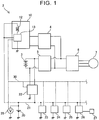
- FIG. 1 is a block diagram of a power system of a fuel cell vehicle 2.
- the fuel cell vehicle 2 of the embodiment includes a fuel cell unit 10, a high-voltage battery 3, a first converter 4, a second converter 5, an inverter 6, a drive motor 7, a third converter 22, an auxiliary battery 20, and auxiliaries 23, 24, 25, 26.
- the fuel cell unit 10 and the high-voltage battery 3 both are power supplies for driving the drive motor 7.
- the auxiliary battery 20 supplies electric power to the auxiliaries 23, 24, 25, 26, and other auxiliaries.
- the auxiliaries collectively denote electrical devices that operate at a voltage that is far lower than a driving voltage of the drive motor 7.
- the output voltage of each of the fuel cell unit 10 and the high-voltage battery 3 is, for example, 200 volts.
- the output voltage of the auxiliary battery 20 is, for example, 12 volts.
- the high-voltage battery 3 is, for example, a battery unit in which a large number of lithium ion battery cells are connected to one another.
- the auxiliary battery 20 is, for example, a lead-acid battery.
- Each of the high-voltage battery 3 and the auxiliary battery 20 is a rechargeable secondary battery (rechargeable battery).
- a main controller 23, an electric power steering system 24, an air conditioner 25, an instrument panel controller 26, and the like, are shown as the auxiliaries.
- the electric power steering system 24 and the air conditioner 25 have a high electric power consumption in the early stage of a startup.
- the fuel cell unit 10 includes a hydrogen injector 12 and an injector controller 13.
- Each of the first to third converters 4, 5, 22 includes a controller.
- the inverter 6 includes a controller.
- the hydrogen injector 12, the injector controller 13, these controllers, and the like, are also included in the auxiliaries.
- a power line 21 runs throughout the body of the fuel cell vehicle 2.
- Each of the auxiliaries is supplied with electric power from the auxiliary battery 20 via the power line 21.
- the auxiliaries are communicably connected to one another via an in-vehicle network 30.
- the broken lines in FIG. 1 indicate the in-vehicle network 30.
- the controller included in the first converter 4, the controller included in the second converter 5, the controller included in the inverter 6, and the like, are also included in the auxiliaries.
- a power line and an in-vehicle network that should be connected to those devices are not shown in FIG. 1 .
- the first converter 4, the second converter 5, and the third converter 22 are voltage converters.
- a low-voltage end of the first converter 4 is connected to an output end of the fuel cell unit 10.
- a high-voltage end of the first converter 4 is connected to a direct-current end of the inverter 6.
- a low-voltage end of the second converter 5 is connected to an output end of the high-voltage battery 3.
- a high-voltage end of the second converter 5 is connected to the direct-current end of the inverter 6.
- the drive motor 7 is connected to an alternating-current end of the inverter 6.
- a high-voltage end of the third converter 22 is connected to the output end of the high-voltage battery 3.
- a low-voltage end of the third converter 22 is connected to the power line 21. Negative electrodes of the auxiliary battery 20 and auxiliaries are connected to a ground.
- the first converter 4 steps up the voltage of electric power that is output from the fuel cell unit 10.
- the second converter 5 has a step-up function and a step-down function. With the step-up function, the second converter 5 steps up the voltage of electric power that is output from the high-voltage battery 3 and supplies the electric power to the inverter 6. With the step-down function, the second converter 5 steps down the voltage of electric power (regenerative electric power which will be described later) that is transferred from the inverter 6 and supplies the electric power to the high-voltage battery 3. That is, the second converter 5 is a bidirectional DC-DC converter. The second converter 5 may step down the voltage of surplus electric power of the fuel cell unit 10 and supply the surplus electric power to the high-voltage battery 3.
- the inverter 6 converts the stepped-up direct-current power of the fuel cell unit 10 or the stepped-up direct-current power of the high-voltage battery 3 to alternating-current power suitable for driving the motor 7.
- the motor 7 is driven by alternating-current power that is supplied from the inverter 6.
- the motor 7 may generate electric power by using the kinetic energy of the vehicle. Electric power generated by the motor 7 is referred to as regenerative electric power.
- the inverter 6 may convert regenerative electric power (alternating-current power) generated by the motor 7 to direct-current power and supply the direct-current power to the second converter 5.
- the fuel cell unit 10 has a long time constant for adjusting output electric power.
- the fuel cell vehicle 2 is equipped with the high-voltage battery 3 in order to compensate for a delay in the response of the fuel cell unit 10.
- the fuel cell vehicle 2 compensates for the shortage with the electric power of the high-voltage battery 3.
- the fuel cell vehicle 2 charges the high-voltage battery 3 with surplus electric power.
- part of the output electric power of the first converter 4 is supplied to the inverter 6, and the remaining part of the output electric power is stepped down by the second converter 5 and is then supplied to the high-voltage battery 3.
- the high-voltage end of the third converter 22 is connected to the high-voltage battery 3.
- the low-voltage end of the third converter 22 is connected to the power line 21 connected to the auxiliaries.
- the third converter 22 steps down the voltage of the output electric power of the high-voltage battery 3 to the voltage level of the auxiliary battery 20, and supplies the electric power to the power line 21.
- the output electric power of the third converter 22 is used to charge the auxiliary battery 20 or to drive the auxiliaries.
- the main controller 23 is a controller that generally controls the whole vehicle, determines the target output power of the motor 7 based on an accelerator operation amount and a vehicle speed, and provides instructions to the fuel cell unit 10, the first converter 4, the second converter 5, and the inverter 6.
- the main controller 23 also transmits an instruction on a target output power to the third converter 22 based on information from a voltage sensor 29.
- the voltage sensor 29 measures the voltage of the auxiliary battery 20.
- the fuel cell unit 10 includes various devices for controlling the fuel cells.
- FIG. 1 shows the hydrogen injector 12 and the injector controller 13 only.
- the hydrogen injector 12 is a device that adjusts the flow rate of hydrogen gas.
- the hydrogen gas is a fuel for the fuel cells.
- the hydrogen injector 12 is an electromagnetically-driven on-off valve, and is of a normally closed type.
- the normally closed-type valve opens when the valve is supplied with a current larger than or equal to a predetermined current threshold, and remains closed when the valve is supplied with a current lower than the current threshold.
- the injector controller 13 controls the current that is supplied to the hydrogen injector 12.
- the injector controller 13 is connected in series with the hydrogen injector 12.
- the hydrogen injector 12 and the injector controller 13 are also auxiliaries. Each of the hydrogen injector 12 and the injector controller 13 is supplied with electric power from the auxiliary battery 20 via the power line 21.
- the injector controller 13 executes feedback control such that the current that is supplied to the hydrogen injector 12 follows a target current value.
- the target current value is obtained by adding a margin to the above-described current threshold.
- the margin is set such that the current that is supplied to the hydrogen injector 12 does not become lower than the current threshold even when the supply current fluctuates during feedback control. In this regard, since an excessively large margin increases consumption of excess electric power, the margin is set to a necessary minimum value.
- the hydrogen injector 12 closes when the supply current becomes lower than the current threshold.
- Various auxiliaries are supplied with electric power from the power line 21.
- a prescribed device such as the air conditioner 25, has a high initial electric power consumption at the time of startup.
- the output power of the auxiliary battery 20 temporarily decreases, with the result that the hydrogen injector 12 possibly closes accidentally.
- the fuel cell vehicle 2 of the embodiment is able to avoid unexpected valve closure of the hydrogen injector 12 due to a shortage of electric power caused by initial electric power consumption of the auxiliaries at the time of startup.
- the mechanism of avoiding unexpected valve closure of the hydrogen injector 12 will be described.
- the air conditioner 25 is started at the time when a user turns on an air-conditioner switch 27 in a vehicle cabin.
- the switch 27 is connected to the instrument panel controller 26.
- the panel controller 26 receives input from the switch 27, the panel controller 26 transmits a start signal to the air conditioner 25 through the in-vehicle network 30.
- a start signal is also transmitted to the injector controller 13 through the in-vehicle network 30.
- the instrument panel controller 26 starts the air conditioner 25, the instrument panel controller 26 transmits a start signal to both the air conditioner 25 and the injector controller 13. Because data included in the start signal indicates an object to be started, the injector controller 13 does not misunderstand the start signal for the air conditioner 25 as a start signal for the injector controller 13 itself.
- the injector controller 13 As the injector controller 13 receives a start signal for a device having a high initial electric power consumption, the injector controller 13 increases the target current value. There is a slight time lag until the air conditioner 25 actually activates its motor upon reception of a start signal. During the time lag, the injector controller 13 increases the current that is supplied to the hydrogen injector 12 such that the supply current follows the increased target current value. After that, as the air conditioner 25 activates the motor, consumption of electric power temporarily increases, and the voltage of the auxiliary battery 20 decreases. As the voltage of the auxiliary battery 20 decreases, the current that is supplied to the hydrogen injector 12 decreases. However, since the target current value has been increased before, even when the current that is supplied to the hydrogen injector 12 temporarily decreases from the target current value, the supply current does not become lower than the current threshold.
- the instrument panel controller 26 transmits an air conditioner stop signal to both the air conditioner 25 and the injector controller 13. As the injector controller 13 detects the air conditioner stop signal, the injector controller 13 returns the target current value to the original value.
- start and stop signals for the air conditioner 25 are transmitted to the injector controller 13 via the in-vehicle network 30.
- the start and stop signals for the electric power steering system 24 are transmitted from the main controller 23 to both the electric power steering system 24 and the injector controller 13.
- the injector controller 13 detects the start signal for the electric power steering system 24, the injector controller 13 increases the target current value, as in the case of the start signal for the air conditioner 25.
- FIG. 2 is a flowchart of the above-described process.
- the injector controller 13 detects a start signal for at least one of the prescribed auxiliaries, the injector controller 13 increases the target current value (Yes in step S2, and step S3).
- the injector controller 13 monitors whether there is a stop signal for at least one of the prescribed auxiliaries (step S4).
- the injector controller 13 detects a stop signal for at least one of the prescribed auxiliaries, the injector controller 13 returns the target current value to the original value (Yes in step S4, and step S5).
- the injector controller 13 ends the process.
- the injector controller 13 periodically repeats the process of FIG. 2 .
- FIG. 3 shows a graph of a variation in the voltage of the auxiliary battery 20 and a graph of a variation in the current that is supplied to the hydrogen injector 12 at the time when the prescribed auxiliary (air conditioner 25) starts or stops.
- the top graph G1 shows a variation in the output voltage of the auxiliary battery 20.
- the bottom graph G2 shows a variation in the target current value.
- the graph G3 shows a variation in the supply current.
- the graph G4 shows a variation in the supply current for the case where the target current value is not increased.
- a current value Ith is a current threshold required to keep the hydrogen injector 12 open.
- a current value Irl is a regular target current value.
- a difference Mgn1 between the regular target current value Ir1 and the current threshold Ith is the margin described above.
- the injector controller 13 At time T1, the user turns on the switch 27, and the instrument panel controller 26 transmits a start signal to the air conditioner 25 and the injector controller 13. As the injector controller 13 detects the start signal, the injector controller 13 increases the target current value Irl to a target current value Ir2. In other words, a margin for ensuring the supply current not to become lower than the current threshold Ith even when the supply current fluctuates is increased from Mgn1 to Mgn2. Since the injector controller 13 is controlling the supply current such that the supply current follows the target current value, the supply current (graph G3) increases with an increase in the target current value (see point P1 in FIG. 3 ).
- the motor of the air conditioner 25 starts a duration dTa behind the detection of the start signal (time T1), the voltage of the auxiliary battery 20 decreases for a while (duration dTb) from time T2 (see point P2 in FIG. 3 ). Because the voltage of the auxiliary battery 20 decreases, the current that is supplied to the hydrogen injector 12 decreases by an amount larger than a fluctuating width of feedback control until then. Since the target current value has been increased, even when the supply current decreases by a large amount, the supply current does not become lower than the current threshold Ith (see point P3 in FIG. 3 ).
- the broken-line graph G4 in FIG. 3 shows the supply current at the time when the target current value is kept at the current value Irl even after reception of the start signal. With a decrease in the voltage of the auxiliary battery 20, the supply current is lower than the current threshold Ith during a duration dTc. If the target current value is not increased, the hydrogen injector 12 possibly closes accidentally during the duration dTc.
- the injector controller 13 detects a stop signal for the air conditioner 25 at time T3. As the injector controller 13 detects the stop signal, the injector controller 13 returns the target current value to the original value Irl.
- the injector controller 13 detects a start signal for the air conditioner 25 (prescribed auxiliary)
- the injector controller 13 increases the target current value of the current that is supplied to the hydrogen injector 12.
- the current that is supplied to the hydrogen injector 12 does not become lower than the current threshold.
- FIG. 4 is a flowchart of supply current control that is executed by the injector controller 13 while electric power supplied from the third converter 22 is taken into consideration.
- the injector controller 13 detects a start signal for at least one of the prescribed auxiliaries (YES in step S12), the injector controller 13 compares the output voltage of the third converter 22 with the output voltage of the auxiliary battery 20 (step S13).
- the output voltage of the third converter 22 is acquired from a voltage sensor (not shown) incorporated in the third converter 22.
- the output voltage of the auxiliary battery 20 is acquired from the voltage sensor 29.
- the injector controller 13 ends the process without increasing the target current value.
- the injector controller 13 detects a start signal for at least one of the prescribed auxiliaries, when the output voltage of the third converter 22 is higher than the output voltage of the auxiliary battery 20, the injector controller 13 prohibits the increase of the target current value.
- the injector controller 13 detects a start signal for at least one of the prescribed auxiliaries, when the output voltage of the third converter 22 is lower than the output voltage of the auxiliary battery 20, the injector controller 13 increases the target current value (NO in step S13, and step S14), as in the case of the above-described embodiment.
- the injector controller 13 returns the target current value to the original value (YES in step S15, and step S16).
- the target current value is not increased, so it is possible to reduce consumption of excess electric power.
- FIG. 5 is a flowchart of supply current control of a second alternative embodiment.
- the injector controller 13 checks whether the output power of the third converter 22 is lower than 70% of full output power (step S23).
- the injector controller 13 carries out communication with the third converter 22 via the in-vehicle network 30, and acquires the level of the output power.
- the injector controller 13 transmits an instruction to the third converter 22 such that the third converter 22 increases the output power (step S25).
- the injector controller 13 increases the target current value (NO in step S23, and step S24).
- the injector controller 13 is able to get the output power level of the third converter 22 by monitoring the duty ratio of a switching element for stepping down the voltage inside the third converter 22.
- the output power of the third converter 22 is increased in preparation for a decrease in the voltage of the auxiliary battery 20.
- the fuel cell vehicle 2 of the embodiment has the following characteristics.
- the fuel cell vehicle 2 includes the fuel cell unit 10, the auxiliary battery 20, and the auxiliary controller.
- the fuel cell unit 10 includes the hydrogen injector 12 and the injector controller 13.
- the hydrogen injector 12 opens when supplied with a current larger than or equal to the predetermined current threshold.
- the injector controller 13 controls a current that is supplied to the hydrogen injector 12 such that the supply current follows the target current value.
- the auxiliary battery 20 supplies electric power to the hydrogen injector 12 and the prescribed auxiliary (such as the air conditioner 25).
- the prescribed auxiliary has a high electric power consumption in the early stage of a startup.
- the auxiliary controller (such as the instrument panel controller 26) transmits a start signal to the prescribed auxiliary. As the injector controller 13 detects that a start signal has been transmitted from the auxiliary controller to the prescribed auxiliary, the injector controller 13 increases the target current value.
- the instrument panel controller 26 or the main controller 23, which transmits a start signal for the prescribed auxiliary is an example of the auxiliary controller.
- the prescribed auxiliary having a high initial electric power consumption by itself may transmit a start signal to the injector controller 13.
- the prescribed auxiliary having a high initial electric power consumption by itself is an example of the auxiliary controller.
- the electric power steering system 24 starts based on its own determination, the electric power steering system 24 transmits a start signal for informing the startup of its own to the injector controller 13.
- the electric power steering system 24 is an example of the auxiliary controller.
- the electric power steering system 24 and the air conditioner 25 are examples of the prescribed auxiliary having a high electric power consumption in the early stage of a startup.
- the prescribed auxiliary having a high electric power consumption in the early stage of a startup is not limited to the electric power steering system 24 or the air conditioner 25.
- the prescribed auxiliary is an auxiliary having a high electric power consumption in the early stage of a startup to such an extent that the electric power consumption influences electric power that is supplied to the hydrogen injector 12, and is determined in advance.
- the prescribed auxiliary is an auxiliary of which the electric power consumption in the early stage of a startup is higher than a predetermined electric power, and is determined in advance.
- the prescribed auxiliary determined in advance is registered in the injector controller 13 or another auxiliary controller.
- the injector controller 31 may constantly monitor a signal that is transferred via the in-vehicle network 30 and, when the monitored signal includes a start signal for the prescribed auxiliary, increase the target current value.
- the process that is executed by the injector controller 13 may be executed by another controller.
- the main controller 23 may execute the process of supply current control in FIG. 2 , the process of supply current control in FIG. 4 , or the process of supply current control in FIG. 5 .
- the main controller 23 is an example of the injector controller.
- the high-voltage end of the third converter 22 may be not connected to the high-voltage battery 3, and may be connected to the output end of the fuel cell unit 10.
Landscapes
- Engineering & Computer Science (AREA)
- Life Sciences & Earth Sciences (AREA)
- Sustainable Development (AREA)
- Sustainable Energy (AREA)
- Power Engineering (AREA)
- Mechanical Engineering (AREA)
- Transportation (AREA)
- Manufacturing & Machinery (AREA)
- Chemical & Material Sciences (AREA)
- Chemical Kinetics & Catalysis (AREA)
- Electrochemistry (AREA)
- General Chemical & Material Sciences (AREA)
- Electric Propulsion And Braking For Vehicles (AREA)
- Fuel Cell (AREA)
Abstract
Description
- The technology disclosed by the present disclosure relates to a fuel cell vehicle.
- A fuel cell unit that is mounted on a fuel cell vehicle includes a hydrogen injector that adjusts the flow rate of hydrogen gas that is a fuel. A typical hydrogen injector is an electromagnetically-driven on-off valve, and is of a normally closed type. The normally closed-type valve remains closed when the valve is not supplied with current, and opens when the valve is supplied with a current exceeding a predetermined current threshold. Japanese Unexamined Patent Application Publication No.
2013-131301 JP 2013-131301 A - A fuel cell vehicle is equipped with a battery (auxiliary battery) that supplies electric power to various auxiliaries. The auxiliaries collectively denote electrical devices that operate at a voltage that is far lower than a driving voltage of a drive motor. Typical auxiliaries include an air conditioner, a car navigation system, an electric power steering system, headlamps, and the like. A hydrogen injector of a fuel cell unit is also a kind of auxiliary. The auxiliary battery and the plurality of auxiliaries (including the hydrogen injector) are connected to each other by a power line. An injector controller sets a target current value to prevent consumption of excess electric power. The target current value is obtained by adding a predetermined margin to a current threshold required to keep the hydrogen injector open. The injector controller controls a current that is supplied to the hydrogen injector such that the supply current follows the target current value. As a prescribed auxiliary having a high initial electric power consumption begins to consume high electric power at the time of startup, the current that is supplied from the auxiliary battery to the hydrogen injector temporarily decreases, with the result that the hydrogen injector possibly closes accidentally.
- An aspect of the invention relates to a fuel cell vehicle including: a hydrogen injector configured to open when a current larger than or equal to a predetermined current threshold is supplied to the hydrogen injector; a controller configured to control the current which is supplied to the hydrogen injector such that the current supplied to the hydrogen injector follows a target current value; and a first power supply configured to supply electric power to the hydrogen injector and a prescribed auxiliary, wherein the controller is configured to increase the target current value when the controller detects at least one of a first start signal for starting the prescribed auxiliary and a second start signal for informing startup of the prescribed auxiliary.
- An example of the prescribed auxiliary is an air conditioner, and an instrument panel controller outputs a start signal to the air conditioner as an air conditioner switch in the cabin is operated . The prescribed auxiliary may be determined in advance and may be registered in the controller.
- The controller executes feedback control such that the supply current follows the target current value. The controller increases the target current value at the time when the controller detects an instruction to start the prescribed auxiliary or a startup of the prescribed auxiliary. Therefore, with the fuel cell vehicle of the above aspect, even when an output voltage of the first power supply temporarily decreases due to startup of the prescribed auxiliary and, as a result, the supply current becomes far lower than the target current value because of delay in feedback control, a sufficient current to keep the valve open is supplied to the hydrogen injector.
- In the above aspect, the fuel cell vehicle may further include: a second power supply having an output voltage which is higher than an output voltage of the first power supply; and a voltage converter configured to step down the output voltage of the second power supply and supply electric power to the first power supply, wherein the controller may be configured not to increase the target current value when an output voltage of the voltage converter exceeds the output voltage of the first power supply.
- With the fuel cell vehicle of the above aspect, even when an output power of the first power supply decreases, but when the electric power that is supplied from the voltage converter is expected, a current at which the hydrogen injector is kept open is obtained without increasing the target current value of the supply current. Therefore, the target current value is not increased, so it is possible to reduce consumption of excess electric power.
- In the above aspect, the fuel cell vehicle may further include: a second power supply having a higher output voltage than the first power supply; and a voltage converter configured to step down the output voltage of the second power supply and supply electric power to the first power supply, wherein: the controller may be configured to, when the voltage converter is operating at a level lower than a predetermined value, not increase the target current value and provide an instruction to the voltage converter to increase output power. The level is a ratio of an output of the voltage converter to a maximum output of the voltage converter.
- When the voltage converter has a reserve capacity, a shortage of electric power of the first power supply is compensated by increasing an output power of the voltage converter, so it is possible to keep the hydrogen injector open. Therefore, with the fuel cell vehicle of the above aspect, it is possible to further reliably handle a decrease in the voltage of the first power supply without increasing the target current value.
- In the above aspect, the controller may be configured to, when the target current value has been increased and the controller detects a stop signal for stopping the prescribed auxiliary, return the target current value to an initial target current value that is a value before the target current value is increased.
- In the above aspect, the initial target current value may be higher than the predetermined current threshold.
- Features, advantages, and technical and industrial significance of exemplary embodiments of the invention will be described below with reference to the accompanying drawings, in which like numerals denote like elements, and wherein:
-
FIG. 1 is a block diagram of a power system of a fuel cell vehicle of an embodiment; -
FIG. 2 is a flowchart of supply current control that is executed by an injector controller; -
FIG. 3 is a graph that shows an example of time variations in a voltage of an auxiliary battery, a target current value, and a supply current; -
FIG. 4 is a flowchart of supply current control of a first alternative embodiment; and -
FIG. 5 is a flowchart of supply current control of a second alternative embodiment. - A fuel cell vehicle of an embodiment will be described with reference to the accompanying drawings.
FIG. 1 is a block diagram of a power system of afuel cell vehicle 2. Thefuel cell vehicle 2 of the embodiment includes afuel cell unit 10, a high-voltage battery 3, afirst converter 4, asecond converter 5, aninverter 6, adrive motor 7, athird converter 22, anauxiliary battery 20, andauxiliaries fuel cell unit 10 and the high-voltage battery 3 both are power supplies for driving thedrive motor 7. Theauxiliary battery 20 supplies electric power to theauxiliaries drive motor 7. The output voltage of each of thefuel cell unit 10 and the high-voltage battery 3 is, for example, 200 volts. The output voltage of theauxiliary battery 20 is, for example, 12 volts. The high-voltage battery 3 is, for example, a battery unit in which a large number of lithium ion battery cells are connected to one another. Theauxiliary battery 20 is, for example, a lead-acid battery. Each of the high-voltage battery 3 and theauxiliary battery 20 is a rechargeable secondary battery (rechargeable battery). - In
FIG. 1 , amain controller 23, an electricpower steering system 24, anair conditioner 25, aninstrument panel controller 26, and the like, are shown as the auxiliaries. The electricpower steering system 24 and theair conditioner 25 have a high electric power consumption in the early stage of a startup. Thefuel cell unit 10 includes ahydrogen injector 12 and aninjector controller 13. Each of the first tothird converters inverter 6 includes a controller. Thehydrogen injector 12, theinjector controller 13, these controllers, and the like, are also included in the auxiliaries. Apower line 21 runs throughout the body of thefuel cell vehicle 2. Each of the auxiliaries is supplied with electric power from theauxiliary battery 20 via thepower line 21. The auxiliaries are communicably connected to one another via an in-vehicle network 30. The broken lines inFIG. 1 indicate the in-vehicle network 30. As described above, the controller included in thefirst converter 4, the controller included in thesecond converter 5, the controller included in theinverter 6, and the like, are also included in the auxiliaries. However, a power line and an in-vehicle network that should be connected to those devices are not shown inFIG. 1 . - The
first converter 4, thesecond converter 5, and thethird converter 22 are voltage converters. A low-voltage end of thefirst converter 4 is connected to an output end of thefuel cell unit 10. A high-voltage end of thefirst converter 4 is connected to a direct-current end of theinverter 6. A low-voltage end of thesecond converter 5 is connected to an output end of the high-voltage battery 3. A high-voltage end of thesecond converter 5 is connected to the direct-current end of theinverter 6. Thedrive motor 7 is connected to an alternating-current end of theinverter 6. A high-voltage end of thethird converter 22 is connected to the output end of the high-voltage battery 3. A low-voltage end of thethird converter 22 is connected to thepower line 21. Negative electrodes of theauxiliary battery 20 and auxiliaries are connected to a ground. - The
first converter 4 steps up the voltage of electric power that is output from thefuel cell unit 10. Thesecond converter 5 has a step-up function and a step-down function. With the step-up function, thesecond converter 5 steps up the voltage of electric power that is output from the high-voltage battery 3 and supplies the electric power to theinverter 6. With the step-down function, thesecond converter 5 steps down the voltage of electric power (regenerative electric power which will be described later) that is transferred from theinverter 6 and supplies the electric power to the high-voltage battery 3. That is, thesecond converter 5 is a bidirectional DC-DC converter. Thesecond converter 5 may step down the voltage of surplus electric power of thefuel cell unit 10 and supply the surplus electric power to the high-voltage battery 3. - The
inverter 6 converts the stepped-up direct-current power of thefuel cell unit 10 or the stepped-up direct-current power of the high-voltage battery 3 to alternating-current power suitable for driving themotor 7. Themotor 7 is driven by alternating-current power that is supplied from theinverter 6. Themotor 7 may generate electric power by using the kinetic energy of the vehicle. Electric power generated by themotor 7 is referred to as regenerative electric power. Theinverter 6 may convert regenerative electric power (alternating-current power) generated by themotor 7 to direct-current power and supply the direct-current power to thesecond converter 5. - An output power required of the
motor 7 frequently varies with accelerator operation of a driver. On the other hand, thefuel cell unit 10 has a long time constant for adjusting output electric power. Thefuel cell vehicle 2 is equipped with the high-voltage battery 3 in order to compensate for a delay in the response of thefuel cell unit 10. When the output electric power of thefuel cell unit 10 is lower than a target output power of themotor 7, thefuel cell vehicle 2 compensates for the shortage with the electric power of the high-voltage battery 3. When the output electric power of thefuel cell unit 10 exceeds the target output power of themotor 7, thefuel cell vehicle 2 charges the high-voltage battery 3 with surplus electric power. In this case, part of the output electric power of thefirst converter 4 is supplied to theinverter 6, and the remaining part of the output electric power is stepped down by thesecond converter 5 and is then supplied to the high-voltage battery 3. - The high-voltage end of the
third converter 22 is connected to the high-voltage battery 3. The low-voltage end of thethird converter 22 is connected to thepower line 21 connected to the auxiliaries. Thethird converter 22 steps down the voltage of the output electric power of the high-voltage battery 3 to the voltage level of theauxiliary battery 20, and supplies the electric power to thepower line 21. The output electric power of thethird converter 22 is used to charge theauxiliary battery 20 or to drive the auxiliaries. - The
main controller 23 is a controller that generally controls the whole vehicle, determines the target output power of themotor 7 based on an accelerator operation amount and a vehicle speed, and provides instructions to thefuel cell unit 10, thefirst converter 4, thesecond converter 5, and theinverter 6. Themain controller 23 also transmits an instruction on a target output power to thethird converter 22 based on information from avoltage sensor 29. Thevoltage sensor 29 measures the voltage of theauxiliary battery 20. - Other than fuel cells (not shown), the
fuel cell unit 10 includes various devices for controlling the fuel cells. However,FIG. 1 shows thehydrogen injector 12 and theinjector controller 13 only. Thehydrogen injector 12 is a device that adjusts the flow rate of hydrogen gas. The hydrogen gas is a fuel for the fuel cells. Thehydrogen injector 12 is an electromagnetically-driven on-off valve, and is of a normally closed type. The normally closed-type valve opens when the valve is supplied with a current larger than or equal to a predetermined current threshold, and remains closed when the valve is supplied with a current lower than the current threshold. Theinjector controller 13 controls the current that is supplied to thehydrogen injector 12. Theinjector controller 13 is connected in series with thehydrogen injector 12. Thehydrogen injector 12 and theinjector controller 13 are also auxiliaries. Each of thehydrogen injector 12 and theinjector controller 13 is supplied with electric power from theauxiliary battery 20 via thepower line 21. - The
injector controller 13 executes feedback control such that the current that is supplied to thehydrogen injector 12 follows a target current value. The target current value is obtained by adding a margin to the above-described current threshold. The margin is set such that the current that is supplied to thehydrogen injector 12 does not become lower than the current threshold even when the supply current fluctuates during feedback control. In this regard, since an excessively large margin increases consumption of excess electric power, the margin is set to a necessary minimum value. - As described above, the
hydrogen injector 12 closes when the supply current becomes lower than the current threshold. Various auxiliaries are supplied with electric power from thepower line 21. A prescribed device, such as theair conditioner 25, has a high initial electric power consumption at the time of startup. As a device having a high initial electric power consumption starts, the output power of theauxiliary battery 20 temporarily decreases, with the result that thehydrogen injector 12 possibly closes accidentally. Thefuel cell vehicle 2 of the embodiment is able to avoid unexpected valve closure of thehydrogen injector 12 due to a shortage of electric power caused by initial electric power consumption of the auxiliaries at the time of startup. Hereinafter, the mechanism of avoiding unexpected valve closure of thehydrogen injector 12 will be described. - The
air conditioner 25 is started at the time when a user turns on an air-conditioner switch 27 in a vehicle cabin. Theswitch 27 is connected to theinstrument panel controller 26. As theinstrument panel controller 26 receives input from theswitch 27, thepanel controller 26 transmits a start signal to theair conditioner 25 through the in-vehicle network 30. In thefuel cell vehicle 2 disclosed in the present specification, when a device having a high initial electric power consumption starts (or is started), a start signal is also transmitted to theinjector controller 13 through the in-vehicle network 30. When theinstrument panel controller 26 starts theair conditioner 25, theinstrument panel controller 26 transmits a start signal to both theair conditioner 25 and theinjector controller 13. Because data included in the start signal indicates an object to be started, theinjector controller 13 does not misunderstand the start signal for theair conditioner 25 as a start signal for theinjector controller 13 itself. - As the
injector controller 13 receives a start signal for a device having a high initial electric power consumption, theinjector controller 13 increases the target current value. There is a slight time lag until theair conditioner 25 actually activates its motor upon reception of a start signal. During the time lag, theinjector controller 13 increases the current that is supplied to thehydrogen injector 12 such that the supply current follows the increased target current value. After that, as theair conditioner 25 activates the motor, consumption of electric power temporarily increases, and the voltage of theauxiliary battery 20 decreases. As the voltage of theauxiliary battery 20 decreases, the current that is supplied to thehydrogen injector 12 decreases. However, since the target current value has been increased before, even when the current that is supplied to thehydrogen injector 12 temporarily decreases from the target current value, the supply current does not become lower than the current threshold. - As the user turns off the
switch 27, theinstrument panel controller 26 transmits an air conditioner stop signal to both theair conditioner 25 and theinjector controller 13. As theinjector controller 13 detects the air conditioner stop signal, theinjector controller 13 returns the target current value to the original value. - Not only the start and stop signals for the
air conditioner 25 but also start and stop signals for an auxiliary having a high initial electric power consumption, that is, for example, the electricpower steering system 24, are transmitted to theinjector controller 13 via the in-vehicle network 30. The start and stop signals for the electricpower steering system 24 are transmitted from themain controller 23 to both the electricpower steering system 24 and theinjector controller 13. As theinjector controller 13 detects the start signal for the electricpower steering system 24, theinjector controller 13 increases the target current value, as in the case of the start signal for theair conditioner 25. -
FIG. 2 is a flowchart of the above-described process. As theinjector controller 13 detects a start signal for at least one of the prescribed auxiliaries, theinjector controller 13 increases the target current value (Yes in step S2, and step S3). When theinjector controller 13 does not detect a start signal for at least one of the prescribed auxiliaries (NO in step S2), theinjector controller 13 monitors whether there is a stop signal for at least one of the prescribed auxiliaries (step S4). As theinjector controller 13 detects a stop signal for at least one of the prescribed auxiliaries, theinjector controller 13 returns the target current value to the original value (Yes in step S4, and step S5). When theinjector controller 13 does not detect a stop signal for at least one of the prescribed auxiliaries, theinjector controller 13 ends the process. Theinjector controller 13 periodically repeats the process ofFIG. 2 . -
FIG. 3 shows a graph of a variation in the voltage of theauxiliary battery 20 and a graph of a variation in the current that is supplied to thehydrogen injector 12 at the time when the prescribed auxiliary (air conditioner 25) starts or stops. The top graph G1 shows a variation in the output voltage of theauxiliary battery 20. The bottom graph G2 shows a variation in the target current value. The graph G3 shows a variation in the supply current. The graph G4 shows a variation in the supply current for the case where the target current value is not increased. A current value Ith is a current threshold required to keep thehydrogen injector 12 open. A current value Irl is a regular target current value. A difference Mgn1 between the regular target current value Ir1 and the current threshold Ith is the margin described above. - At time T1, the user turns on the
switch 27, and theinstrument panel controller 26 transmits a start signal to theair conditioner 25 and theinjector controller 13. As theinjector controller 13 detects the start signal, theinjector controller 13 increases the target current value Irl to a target current value Ir2. In other words, a margin for ensuring the supply current not to become lower than the current threshold Ith even when the supply current fluctuates is increased from Mgn1 to Mgn2. Since theinjector controller 13 is controlling the supply current such that the supply current follows the target current value, the supply current (graph G3) increases with an increase in the target current value (see point P1 inFIG. 3 ). - As the motor of the
air conditioner 25 starts a duration dTa behind the detection of the start signal (time T1), the voltage of theauxiliary battery 20 decreases for a while (duration dTb) from time T2 (see point P2 inFIG. 3 ). Because the voltage of theauxiliary battery 20 decreases, the current that is supplied to thehydrogen injector 12 decreases by an amount larger than a fluctuating width of feedback control until then. Since the target current value has been increased, even when the supply current decreases by a large amount, the supply current does not become lower than the current threshold Ith (see point P3 inFIG. 3 ). - The broken-line graph G4 in
FIG. 3 shows the supply current at the time when the target current value is kept at the current value Irl even after reception of the start signal. With a decrease in the voltage of theauxiliary battery 20, the supply current is lower than the current threshold Ith during a duration dTc. If the target current value is not increased, thehydrogen injector 12 possibly closes accidentally during the duration dTc. - The
injector controller 13 detects a stop signal for theair conditioner 25 at time T3. As theinjector controller 13 detects the stop signal, theinjector controller 13 returns the target current value to the original value Irl. - As described above, in the
fuel cell vehicle 2 of the embodiment, as theinjector controller 13 detects a start signal for the air conditioner 25 (prescribed auxiliary), theinjector controller 13 increases the target current value of the current that is supplied to thehydrogen injector 12. As a result, even when the voltage of theauxiliary battery 20 decreases as a result of a temporary increase in electric power consumption at the time of startup of the prescribed auxiliary, the current that is supplied to thehydrogen injector 12 does not become lower than the current threshold. - As described above, the low-voltage end of the
third converter 22 is connected to thepower line 21 that transfers the electric power of theauxiliary battery 20 to the auxiliaries, and the electric power of the high-voltage battery 3 is supplied to thepower line 21 via thethird converter 22. If the electric power of the high-voltage battery 3 is able to compensate for a shortage of output power of theauxiliary battery 20, theinjector controller 13 does not need to increase the target current value.FIG. 4 is a flowchart of supply current control that is executed by theinjector controller 13 while electric power supplied from thethird converter 22 is taken into consideration. - As the
injector controller 13 detects a start signal for at least one of the prescribed auxiliaries (YES in step S12), theinjector controller 13 compares the output voltage of thethird converter 22 with the output voltage of the auxiliary battery 20 (step S13). The output voltage of thethird converter 22 is acquired from a voltage sensor (not shown) incorporated in thethird converter 22. The output voltage of theauxiliary battery 20 is acquired from thevoltage sensor 29. When the output voltage of thethird converter 22 is higher than the output voltage of the auxiliary battery 20 (YES in step S13), theinjector controller 13 ends the process without increasing the target current value. In other words, after theinjector controller 13 detects a start signal for at least one of the prescribed auxiliaries, when the output voltage of thethird converter 22 is higher than the output voltage of theauxiliary battery 20, theinjector controller 13 prohibits the increase of the target current value. After theinjector controller 13 detects a start signal for at least one of the prescribed auxiliaries, when the output voltage of thethird converter 22 is lower than the output voltage of theauxiliary battery 20, theinjector controller 13 increases the target current value (NO in step S13, and step S14), as in the case of the above-described embodiment. When the target current value has been increased before at the time when theinjector controller 13 detects a stop signal for at least one of the prescribed auxiliaries, theinjector controller 13 returns the target current value to the original value (YES in step S15, and step S16). - With the process of the first alternative embodiment, when it is possible to handle a decrease in the voltage of the
auxiliary battery 20 without increasing the target current value, the target current value is not increased, so it is possible to reduce consumption of excess electric power. -
FIG. 5 is a flowchart of supply current control of a second alternative embodiment. In the second alternative embodiment, after theinjector controller 13 detects a start signal for at least any one of the prescribed auxiliaries (YES in step S22), theinjector controller 13 checks whether the output power of thethird converter 22 is lower than 70% of full output power (step S23). Theinjector controller 13 carries out communication with thethird converter 22 via the in-vehicle network 30, and acquires the level of the output power. When the output power of thethird converter 22 is lower than 70% of the full output power (YES in step S23), theinjector controller 13 transmits an instruction to thethird converter 22 such that thethird converter 22 increases the output power (step S25). When the output power of thethird converter 22 is higher than or equal to 70% of the full output power, theinjector controller 13 increases the target current value (NO in step S23, and step S24). - When the
third converter 22 operates under duty control, a duty ratio corresponds to the output power level. Therefore, theinjector controller 13 is able to get the output power level of thethird converter 22 by monitoring the duty ratio of a switching element for stepping down the voltage inside thethird converter 22. - With the process of the second alternative embodiment, when the
third converter 22 has a reserve capacity, the output power of thethird converter 22 is increased in preparation for a decrease in the voltage of theauxiliary battery 20. By so doing, it is possible to further reliably handle a decrease in the voltage of theauxiliary battery 20 without increasing the target current value. - The
fuel cell vehicle 2 of the embodiment has the following characteristics. Thefuel cell vehicle 2 includes thefuel cell unit 10, theauxiliary battery 20, and the auxiliary controller. Thefuel cell unit 10 includes thehydrogen injector 12 and theinjector controller 13. Thehydrogen injector 12 opens when supplied with a current larger than or equal to the predetermined current threshold. Theinjector controller 13 controls a current that is supplied to thehydrogen injector 12 such that the supply current follows the target current value. Theauxiliary battery 20 supplies electric power to thehydrogen injector 12 and the prescribed auxiliary (such as the air conditioner 25). The prescribed auxiliary has a high electric power consumption in the early stage of a startup. The auxiliary controller (such as the instrument panel controller 26) transmits a start signal to the prescribed auxiliary. As theinjector controller 13 detects that a start signal has been transmitted from the auxiliary controller to the prescribed auxiliary, theinjector controller 13 increases the target current value. - The
instrument panel controller 26 or themain controller 23, which transmits a start signal for the prescribed auxiliary, is an example of the auxiliary controller. The prescribed auxiliary having a high initial electric power consumption by itself may transmit a start signal to theinjector controller 13. In this case, the prescribed auxiliary having a high initial electric power consumption by itself is an example of the auxiliary controller. When the electricpower steering system 24 starts based on its own determination, the electricpower steering system 24 transmits a start signal for informing the startup of its own to theinjector controller 13. In this case, the electricpower steering system 24 is an example of the auxiliary controller. - Not all the auxiliary controllers need to transmit a start signal to the
injector controller 13. The auxiliary controller of the prescribed auxiliary of which an electric power consumption in the early stage of a startup exceeds a predetermined value just needs to transmit a start signal to theinjector controller 13. In the embodiment, the electricpower steering system 24 and theair conditioner 25 are examples of the prescribed auxiliary having a high electric power consumption in the early stage of a startup. The prescribed auxiliary having a high electric power consumption in the early stage of a startup is not limited to the electricpower steering system 24 or theair conditioner 25. The prescribed auxiliary is an auxiliary having a high electric power consumption in the early stage of a startup to such an extent that the electric power consumption influences electric power that is supplied to thehydrogen injector 12, and is determined in advance. In other words, the prescribed auxiliary is an auxiliary of which the electric power consumption in the early stage of a startup is higher than a predetermined electric power, and is determined in advance. The prescribed auxiliary determined in advance is registered in theinjector controller 13 or another auxiliary controller. - Instead of the configuration that the auxiliary controller transmits a start signal to the
injector controller 13, the injector controller 31 may constantly monitor a signal that is transferred via the in-vehicle network 30 and, when the monitored signal includes a start signal for the prescribed auxiliary, increase the target current value. - The process that is executed by the
injector controller 13 may be executed by another controller. For example, themain controller 23 may execute the process of supply current control inFIG. 2 , the process of supply current control inFIG. 4 , or the process of supply current control inFIG. 5 . In this case, themain controller 23 is an example of the injector controller. - The high-voltage end of the
third converter 22 may be not connected to the high-voltage battery 3, and may be connected to the output end of thefuel cell unit 10. - Specific embodiments of the invention are described in detail. However, the invention is not limited to these examples. The specific embodiments illustrated above may be variously modified or altered.
Claims (5)
- A fuel cell vehicle comprising:a hydrogen injector (12) configured to open when a current larger than or equal to a predetermined current threshold (Ith) is supplied to the hydrogen injector (12);a controller (13) configured to control the current which is supplied to the hydrogen injector (12) such that the current supplied to the hydrogen injector (12) follows a target current value; anda first power supply (20) configured to supply electric power to the hydrogen injector (12) and a prescribed auxiliary, wherein the controller (13) is configured to increase the target current value when the controller (13) detects at least one of a first start signal for starting the prescribed auxiliary and a second start signal for informing startup of the prescribed auxiliary.
- The fuel cell vehicle according to claim 1, further comprising:a second power supply (3) having an output voltage which is higher than an output voltage of the first power supply (20); anda voltage converter (22) configured to step down the output voltage of the second power supply (3) and supply electric power to the first power supply (20), wherein the controller (13) is configured not to increase the target current value when an output voltage of the voltage converter (22) exceeds the output voltage of the first power supply (20).
- The fuel cell vehicle according to claim 1, further comprising:a second power supply (3) having a higher output voltage than the first power supply (20); anda voltage converter (22) configured to step down the output voltage of the second power supply (3) and supply electric power to the first power supply (20), wherein:the controller (13) is configured to, when the voltage converter (22) is operating at a level lower than a predetermined value, not increase the target current value and provide an instruction to the voltage converter (22) to increase output power; andthe level being a ratio of an output of the voltage converter (22) to a maximum output of the voltage converter (22).
- The fuel cell vehicle according to any one of claims 1 to 3, wherein the controller (13) is configured to, when the target current value has been increased and the controller (13) detects a stop signal for stopping the prescribed auxiliary, return the target current value to an initial target current value (Ir1) that is a value before the target current value is increased.
- The fuel cell vehicle according to claim 4, wherein the initial target current value (Ir1) is higher than the predetermined current threshold (Ith).
Applications Claiming Priority (1)
| Application Number | Priority Date | Filing Date | Title |
|---|---|---|---|
| JP2017203158A JP6881224B2 (en) | 2017-10-20 | 2017-10-20 | Fuel cell vehicle |
Publications (2)
| Publication Number | Publication Date |
|---|---|
| EP3473481A1 true EP3473481A1 (en) | 2019-04-24 |
| EP3473481B1 EP3473481B1 (en) | 2022-11-09 |
Family
ID=63165203
Family Applications (1)
| Application Number | Title | Priority Date | Filing Date |
|---|---|---|---|
| EP18187357.1A Active EP3473481B1 (en) | 2017-10-20 | 2018-08-03 | Fuel cell vehicle |
Country Status (4)
| Country | Link |
|---|---|
| US (1) | US11289724B2 (en) |
| EP (1) | EP3473481B1 (en) |
| JP (1) | JP6881224B2 (en) |
| CN (1) | CN110015207B (en) |
Cited By (1)
| Publication number | Priority date | Publication date | Assignee | Title |
|---|---|---|---|---|
| FR3106533A1 (en) * | 2020-01-27 | 2021-07-30 | Centum Adeneo | Road vehicle using a fuel cell |
Families Citing this family (1)
| Publication number | Priority date | Publication date | Assignee | Title |
|---|---|---|---|---|
| CN113306456B (en) * | 2021-06-01 | 2023-01-06 | 东风柳州汽车有限公司 | Power distribution control method and device for hydrogen fuel cargo van type medical vehicle |
Citations (3)
| Publication number | Priority date | Publication date | Assignee | Title |
|---|---|---|---|---|
| JP2013131301A (en) | 2011-12-20 | 2013-07-04 | Toyota Motor Corp | Fuel cell system |
| WO2017077779A1 (en) * | 2015-11-05 | 2017-05-11 | 株式会社デンソー | Fuel injection control device and fuel injection system |
| JP2017147135A (en) * | 2016-02-18 | 2017-08-24 | 本田技研工業株式会社 | Control method for fuel cell system |
Family Cites Families (14)
| Publication number | Priority date | Publication date | Assignee | Title |
|---|---|---|---|---|
| JP2865193B2 (en) * | 1994-09-20 | 1999-03-08 | 本田技研工業株式会社 | Fuel supply control device |
| JP2002021679A (en) * | 2000-06-30 | 2002-01-23 | Hitachi Ltd | Fuel injection device and internal combustion engine |
| JP2002237410A (en) * | 2001-02-08 | 2002-08-23 | Denso Corp | Solenoid valve drive circuit |
| JP2002357149A (en) * | 2001-05-31 | 2002-12-13 | Aisan Ind Co Ltd | Drive circuit of electromagnetic fuel injection valve |
| JP5041272B2 (en) * | 2005-12-12 | 2012-10-03 | トヨタ自動車株式会社 | Fuel cell system and moving body |
| JP2007205220A (en) * | 2006-02-01 | 2007-08-16 | Nikki Co Ltd | Fuel injection valve control device for gas fuel engine |
| JP5007797B2 (en) * | 2006-11-30 | 2012-08-22 | トヨタ自動車株式会社 | Fuel cell system |
| JP5011021B2 (en) * | 2007-08-01 | 2012-08-29 | 本田技研工業株式会社 | Fuel cell system |
| JP4789018B2 (en) * | 2008-01-28 | 2011-10-05 | トヨタ自動車株式会社 | Fuel cell system |
| JP2011028950A (en) * | 2009-07-23 | 2011-02-10 | Toyota Motor Corp | Fuel injection control device |
| US8679691B2 (en) * | 2011-08-05 | 2014-03-25 | GM Global Technology Operations LLC | Injector opening delay diagnostic strategy |
| US9543600B2 (en) * | 2012-11-21 | 2017-01-10 | Honda Motor Co., Ltd. | Fuel cell system |
| JP6167864B2 (en) | 2013-11-11 | 2017-07-26 | トヨタ自動車株式会社 | FUEL CELL SYSTEM, FUEL CELL VEHICLE, AND METHOD FOR CONTROLLING FUEL CELL SYSTEM |
| US11214170B2 (en) * | 2017-08-14 | 2022-01-04 | Nissan Motor Co., Ltd. | Power supply system and operation method thereof |
-
2017
- 2017-10-20 JP JP2017203158A patent/JP6881224B2/en active Active
-
2018
- 2018-08-03 EP EP18187357.1A patent/EP3473481B1/en active Active
- 2018-08-07 CN CN201810889570.9A patent/CN110015207B/en active Active
- 2018-08-09 US US16/059,649 patent/US11289724B2/en active Active
Patent Citations (4)
| Publication number | Priority date | Publication date | Assignee | Title |
|---|---|---|---|---|
| JP2013131301A (en) | 2011-12-20 | 2013-07-04 | Toyota Motor Corp | Fuel cell system |
| WO2017077779A1 (en) * | 2015-11-05 | 2017-05-11 | 株式会社デンソー | Fuel injection control device and fuel injection system |
| US20180320620A1 (en) * | 2015-11-05 | 2018-11-08 | Denso Corporation | Fuel injection control device and fuel injection system |
| JP2017147135A (en) * | 2016-02-18 | 2017-08-24 | 本田技研工業株式会社 | Control method for fuel cell system |
Cited By (1)
| Publication number | Priority date | Publication date | Assignee | Title |
|---|---|---|---|---|
| FR3106533A1 (en) * | 2020-01-27 | 2021-07-30 | Centum Adeneo | Road vehicle using a fuel cell |
Also Published As
| Publication number | Publication date |
|---|---|
| CN110015207B (en) | 2022-06-28 |
| JP6881224B2 (en) | 2021-06-02 |
| CN110015207A (en) | 2019-07-16 |
| EP3473481B1 (en) | 2022-11-09 |
| US11289724B2 (en) | 2022-03-29 |
| JP2019079604A (en) | 2019-05-23 |
| US20190123366A1 (en) | 2019-04-25 |
Similar Documents
| Publication | Publication Date | Title |
|---|---|---|
| US9768639B2 (en) | Vehicle-mounted power source device | |
| US11628736B2 (en) | Solar charging system and vehicle | |
| KR101139022B1 (en) | On-vehicle power supplying apparatus with two power supplies | |
| US9387763B2 (en) | Power source device for vehicle | |
| JP5434196B2 (en) | Fuel cell system and vehicle equipped with the same | |
| EP2580839B1 (en) | Battery charging system | |
| US9731619B2 (en) | Vehicle and control method for vehicle | |
| US10906415B2 (en) | Power source system for vehicle | |
| EP2691254B1 (en) | Charging device for vehicle, vehicle equipped with charging device, and offset correction method for current sensor | |
| JP6056486B2 (en) | Vehicle power supply device | |
| US10293703B2 (en) | Method for controlling a voltage source for charging a battery of a motor vehicle | |
| US11053714B2 (en) | Door latch power supply device, door latch power supply system, and vehicle using same | |
| US11705567B2 (en) | Fuel cell system, non-transitory storage medium and control method for fuel cell system | |
| EP3761493A1 (en) | Dc-dc converter control apparatus and dc-dc converter control method | |
| US6812672B2 (en) | Electric charge control device and load driving device using the same | |
| US20230069428A1 (en) | Fuel cell vehicle | |
| JP2020089100A (en) | Vehicle charge control system | |
| EP3473481B1 (en) | Fuel cell vehicle | |
| CN105849997B (en) | Power control device and power control method | |
| JP2006136170A (en) | Dual power supply type vehicle power supply | |
| CN102379060B (en) | Fuel cell system, and vehicle equipped with the fuel cell system | |
| US11155221B2 (en) | Power supply device for vehicle | |
| US11962183B2 (en) | Backup power system | |
| US20250211015A1 (en) | Charge control device | |
| JP2023184332A (en) | solar cell system |
Legal Events
| Date | Code | Title | Description |
|---|---|---|---|
| PUAI | Public reference made under article 153(3) epc to a published international application that has entered the european phase |
Free format text: ORIGINAL CODE: 0009012 |
|
| STAA | Information on the status of an ep patent application or granted ep patent |
Free format text: STATUS: REQUEST FOR EXAMINATION WAS MADE |
|
| 17P | Request for examination filed |
Effective date: 20180803 |
|
| AK | Designated contracting states |
Kind code of ref document: A1 Designated state(s): AL AT BE BG CH CY CZ DE DK EE ES FI FR GB GR HR HU IE IS IT LI LT LU LV MC MK MT NL NO PL PT RO RS SE SI SK SM TR |
|
| AX | Request for extension of the european patent |
Extension state: BA ME |
|
| STAA | Information on the status of an ep patent application or granted ep patent |
Free format text: STATUS: EXAMINATION IS IN PROGRESS |
|
| 17Q | First examination report despatched |
Effective date: 20200616 |
|
| GRAP | Despatch of communication of intention to grant a patent |
Free format text: ORIGINAL CODE: EPIDOSNIGR1 |
|
| STAA | Information on the status of an ep patent application or granted ep patent |
Free format text: STATUS: GRANT OF PATENT IS INTENDED |
|
| GRAJ | Information related to disapproval of communication of intention to grant by the applicant or resumption of examination proceedings by the epo deleted |
Free format text: ORIGINAL CODE: EPIDOSDIGR1 |
|
| STAA | Information on the status of an ep patent application or granted ep patent |
Free format text: STATUS: EXAMINATION IS IN PROGRESS |
|
| RIC1 | Information provided on ipc code assigned before grant |
Ipc: H01M 8/04858 20160101ALI20220420BHEP Ipc: H01M 8/04537 20160101ALI20220420BHEP Ipc: H01M 8/04082 20160101ALI20220420BHEP Ipc: H01M 8/04089 20160101ALI20220420BHEP Ipc: B60L 58/20 20190101ALI20220420BHEP Ipc: B60L 58/30 20190101ALI20220420BHEP Ipc: B60L 58/40 20190101ALI20220420BHEP Ipc: B60L 50/70 20190101ALI20220420BHEP Ipc: B60L 50/75 20190101ALI20220420BHEP Ipc: H01M 8/0438 20160101ALI20220420BHEP Ipc: H01M 8/04746 20160101ALI20220420BHEP Ipc: B60L 1/00 20060101AFI20220420BHEP |
|
| INTG | Intention to grant announced |
Effective date: 20220510 |
|
| INTC | Intention to grant announced (deleted) | ||
| GRAP | Despatch of communication of intention to grant a patent |
Free format text: ORIGINAL CODE: EPIDOSNIGR1 |
|
| STAA | Information on the status of an ep patent application or granted ep patent |
Free format text: STATUS: GRANT OF PATENT IS INTENDED |
|
| INTG | Intention to grant announced |
Effective date: 20220628 |
|
| GRAS | Grant fee paid |
Free format text: ORIGINAL CODE: EPIDOSNIGR3 |
|
| GRAA | (expected) grant |
Free format text: ORIGINAL CODE: 0009210 |
|
| STAA | Information on the status of an ep patent application or granted ep patent |
Free format text: STATUS: THE PATENT HAS BEEN GRANTED |
|
| AK | Designated contracting states |
Kind code of ref document: B1 Designated state(s): AL AT BE BG CH CY CZ DE DK EE ES FI FR GB GR HR HU IE IS IT LI LT LU LV MC MK MT NL NO PL PT RO RS SE SI SK SM TR |
|
| REG | Reference to a national code |
Ref country code: GB Ref legal event code: FG4D |
|
| REG | Reference to a national code |
Ref country code: CH Ref legal event code: EP Ref country code: AT Ref legal event code: REF Ref document number: 1530134 Country of ref document: AT Kind code of ref document: T Effective date: 20221115 |
|
| REG | Reference to a national code |
Ref country code: DE Ref legal event code: R096 Ref document number: 602018042779 Country of ref document: DE |
|
| REG | Reference to a national code |
Ref country code: IE Ref legal event code: FG4D |
|
| REG | Reference to a national code |
Ref country code: LT Ref legal event code: MG9D |
|
| REG | Reference to a national code |
Ref country code: NL Ref legal event code: MP Effective date: 20221109 |
|
| REG | Reference to a national code |
Ref country code: AT Ref legal event code: MK05 Ref document number: 1530134 Country of ref document: AT Kind code of ref document: T Effective date: 20221109 |
|
| PG25 | Lapsed in a contracting state [announced via postgrant information from national office to epo] |
Ref country code: SE Free format text: LAPSE BECAUSE OF FAILURE TO SUBMIT A TRANSLATION OF THE DESCRIPTION OR TO PAY THE FEE WITHIN THE PRESCRIBED TIME-LIMIT Effective date: 20221109 Ref country code: PT Free format text: LAPSE BECAUSE OF FAILURE TO SUBMIT A TRANSLATION OF THE DESCRIPTION OR TO PAY THE FEE WITHIN THE PRESCRIBED TIME-LIMIT Effective date: 20230309 Ref country code: NO Free format text: LAPSE BECAUSE OF FAILURE TO SUBMIT A TRANSLATION OF THE DESCRIPTION OR TO PAY THE FEE WITHIN THE PRESCRIBED TIME-LIMIT Effective date: 20230209 Ref country code: LT Free format text: LAPSE BECAUSE OF FAILURE TO SUBMIT A TRANSLATION OF THE DESCRIPTION OR TO PAY THE FEE WITHIN THE PRESCRIBED TIME-LIMIT Effective date: 20221109 Ref country code: FI Free format text: LAPSE BECAUSE OF FAILURE TO SUBMIT A TRANSLATION OF THE DESCRIPTION OR TO PAY THE FEE WITHIN THE PRESCRIBED TIME-LIMIT Effective date: 20221109 Ref country code: ES Free format text: LAPSE BECAUSE OF FAILURE TO SUBMIT A TRANSLATION OF THE DESCRIPTION OR TO PAY THE FEE WITHIN THE PRESCRIBED TIME-LIMIT Effective date: 20221109 Ref country code: AT Free format text: LAPSE BECAUSE OF FAILURE TO SUBMIT A TRANSLATION OF THE DESCRIPTION OR TO PAY THE FEE WITHIN THE PRESCRIBED TIME-LIMIT Effective date: 20221109 |
|
| PG25 | Lapsed in a contracting state [announced via postgrant information from national office to epo] |
Ref country code: RS Free format text: LAPSE BECAUSE OF FAILURE TO SUBMIT A TRANSLATION OF THE DESCRIPTION OR TO PAY THE FEE WITHIN THE PRESCRIBED TIME-LIMIT Effective date: 20221109 Ref country code: PL Free format text: LAPSE BECAUSE OF FAILURE TO SUBMIT A TRANSLATION OF THE DESCRIPTION OR TO PAY THE FEE WITHIN THE PRESCRIBED TIME-LIMIT Effective date: 20221109 Ref country code: LV Free format text: LAPSE BECAUSE OF FAILURE TO SUBMIT A TRANSLATION OF THE DESCRIPTION OR TO PAY THE FEE WITHIN THE PRESCRIBED TIME-LIMIT Effective date: 20221109 Ref country code: IS Free format text: LAPSE BECAUSE OF FAILURE TO SUBMIT A TRANSLATION OF THE DESCRIPTION OR TO PAY THE FEE WITHIN THE PRESCRIBED TIME-LIMIT Effective date: 20230309 Ref country code: HR Free format text: LAPSE BECAUSE OF FAILURE TO SUBMIT A TRANSLATION OF THE DESCRIPTION OR TO PAY THE FEE WITHIN THE PRESCRIBED TIME-LIMIT Effective date: 20221109 Ref country code: GR Free format text: LAPSE BECAUSE OF FAILURE TO SUBMIT A TRANSLATION OF THE DESCRIPTION OR TO PAY THE FEE WITHIN THE PRESCRIBED TIME-LIMIT Effective date: 20230210 |
|
| REG | Reference to a national code |
Ref country code: DE Ref legal event code: R084 Ref document number: 602018042779 Country of ref document: DE |
|
| PG25 | Lapsed in a contracting state [announced via postgrant information from national office to epo] |
Ref country code: NL Free format text: LAPSE BECAUSE OF FAILURE TO SUBMIT A TRANSLATION OF THE DESCRIPTION OR TO PAY THE FEE WITHIN THE PRESCRIBED TIME-LIMIT Effective date: 20221109 |
|
| PG25 | Lapsed in a contracting state [announced via postgrant information from national office to epo] |
Ref country code: SM Free format text: LAPSE BECAUSE OF FAILURE TO SUBMIT A TRANSLATION OF THE DESCRIPTION OR TO PAY THE FEE WITHIN THE PRESCRIBED TIME-LIMIT Effective date: 20221109 Ref country code: RO Free format text: LAPSE BECAUSE OF FAILURE TO SUBMIT A TRANSLATION OF THE DESCRIPTION OR TO PAY THE FEE WITHIN THE PRESCRIBED TIME-LIMIT Effective date: 20221109 Ref country code: EE Free format text: LAPSE BECAUSE OF FAILURE TO SUBMIT A TRANSLATION OF THE DESCRIPTION OR TO PAY THE FEE WITHIN THE PRESCRIBED TIME-LIMIT Effective date: 20221109 Ref country code: DK Free format text: LAPSE BECAUSE OF FAILURE TO SUBMIT A TRANSLATION OF THE DESCRIPTION OR TO PAY THE FEE WITHIN THE PRESCRIBED TIME-LIMIT Effective date: 20221109 Ref country code: CZ Free format text: LAPSE BECAUSE OF FAILURE TO SUBMIT A TRANSLATION OF THE DESCRIPTION OR TO PAY THE FEE WITHIN THE PRESCRIBED TIME-LIMIT Effective date: 20221109 |
|
| REG | Reference to a national code |
Ref country code: DE Ref legal event code: R097 Ref document number: 602018042779 Country of ref document: DE |
|
| PG25 | Lapsed in a contracting state [announced via postgrant information from national office to epo] |
Ref country code: SK Free format text: LAPSE BECAUSE OF FAILURE TO SUBMIT A TRANSLATION OF THE DESCRIPTION OR TO PAY THE FEE WITHIN THE PRESCRIBED TIME-LIMIT Effective date: 20221109 Ref country code: AL Free format text: LAPSE BECAUSE OF FAILURE TO SUBMIT A TRANSLATION OF THE DESCRIPTION OR TO PAY THE FEE WITHIN THE PRESCRIBED TIME-LIMIT Effective date: 20221109 |
|
| PLBE | No opposition filed within time limit |
Free format text: ORIGINAL CODE: 0009261 |
|
| STAA | Information on the status of an ep patent application or granted ep patent |
Free format text: STATUS: NO OPPOSITION FILED WITHIN TIME LIMIT |
|
| 26N | No opposition filed |
Effective date: 20230810 |
|
| P01 | Opt-out of the competence of the unified patent court (upc) registered |
Effective date: 20231024 |
|
| PG25 | Lapsed in a contracting state [announced via postgrant information from national office to epo] |
Ref country code: SI Free format text: LAPSE BECAUSE OF FAILURE TO SUBMIT A TRANSLATION OF THE DESCRIPTION OR TO PAY THE FEE WITHIN THE PRESCRIBED TIME-LIMIT Effective date: 20221109 |
|
| PG25 | Lapsed in a contracting state [announced via postgrant information from national office to epo] |
Ref country code: MC Free format text: LAPSE BECAUSE OF FAILURE TO SUBMIT A TRANSLATION OF THE DESCRIPTION OR TO PAY THE FEE WITHIN THE PRESCRIBED TIME-LIMIT Effective date: 20221109 |
|
| REG | Reference to a national code |
Ref country code: CH Ref legal event code: PL |
|
| PG25 | Lapsed in a contracting state [announced via postgrant information from national office to epo] |
Ref country code: MC Free format text: LAPSE BECAUSE OF FAILURE TO SUBMIT A TRANSLATION OF THE DESCRIPTION OR TO PAY THE FEE WITHIN THE PRESCRIBED TIME-LIMIT Effective date: 20221109 |
|
| PG25 | Lapsed in a contracting state [announced via postgrant information from national office to epo] |
Ref country code: LU Free format text: LAPSE BECAUSE OF NON-PAYMENT OF DUE FEES Effective date: 20230803 |
|
| GBPC | Gb: european patent ceased through non-payment of renewal fee |
Effective date: 20230803 |
|
| PG25 | Lapsed in a contracting state [announced via postgrant information from national office to epo] |
Ref country code: LU Free format text: LAPSE BECAUSE OF NON-PAYMENT OF DUE FEES Effective date: 20230803 Ref country code: CH Free format text: LAPSE BECAUSE OF NON-PAYMENT OF DUE FEES Effective date: 20230831 |
|
| REG | Reference to a national code |
Ref country code: BE Ref legal event code: MM Effective date: 20230831 |
|
| REG | Reference to a national code |
Ref country code: IE Ref legal event code: MM4A |
|
| PG25 | Lapsed in a contracting state [announced via postgrant information from national office to epo] |
Ref country code: IT Free format text: LAPSE BECAUSE OF FAILURE TO SUBMIT A TRANSLATION OF THE DESCRIPTION OR TO PAY THE FEE WITHIN THE PRESCRIBED TIME-LIMIT Effective date: 20221109 |
|
| PG25 | Lapsed in a contracting state [announced via postgrant information from national office to epo] |
Ref country code: IE Free format text: LAPSE BECAUSE OF NON-PAYMENT OF DUE FEES Effective date: 20230803 |
|
| PG25 | Lapsed in a contracting state [announced via postgrant information from national office to epo] |
Ref country code: GB Free format text: LAPSE BECAUSE OF NON-PAYMENT OF DUE FEES Effective date: 20230803 |
|
| PG25 | Lapsed in a contracting state [announced via postgrant information from national office to epo] |
Ref country code: IE Free format text: LAPSE BECAUSE OF NON-PAYMENT OF DUE FEES Effective date: 20230803 Ref country code: GB Free format text: LAPSE BECAUSE OF NON-PAYMENT OF DUE FEES Effective date: 20230803 Ref country code: FR Free format text: LAPSE BECAUSE OF NON-PAYMENT OF DUE FEES Effective date: 20230831 |
|
| PG25 | Lapsed in a contracting state [announced via postgrant information from national office to epo] |
Ref country code: BE Free format text: LAPSE BECAUSE OF NON-PAYMENT OF DUE FEES Effective date: 20230831 |
|
| PG25 | Lapsed in a contracting state [announced via postgrant information from national office to epo] |
Ref country code: BG Free format text: LAPSE BECAUSE OF FAILURE TO SUBMIT A TRANSLATION OF THE DESCRIPTION OR TO PAY THE FEE WITHIN THE PRESCRIBED TIME-LIMIT Effective date: 20221109 |
|
| PG25 | Lapsed in a contracting state [announced via postgrant information from national office to epo] |
Ref country code: BG Free format text: LAPSE BECAUSE OF FAILURE TO SUBMIT A TRANSLATION OF THE DESCRIPTION OR TO PAY THE FEE WITHIN THE PRESCRIBED TIME-LIMIT Effective date: 20221109 |
|
| PG25 | Lapsed in a contracting state [announced via postgrant information from national office to epo] |
Ref country code: CY Free format text: LAPSE BECAUSE OF FAILURE TO SUBMIT A TRANSLATION OF THE DESCRIPTION OR TO PAY THE FEE WITHIN THE PRESCRIBED TIME-LIMIT; INVALID AB INITIO Effective date: 20180803 |
|
| PG25 | Lapsed in a contracting state [announced via postgrant information from national office to epo] |
Ref country code: HU Free format text: LAPSE BECAUSE OF FAILURE TO SUBMIT A TRANSLATION OF THE DESCRIPTION OR TO PAY THE FEE WITHIN THE PRESCRIBED TIME-LIMIT; INVALID AB INITIO Effective date: 20180803 |
|
| PGFP | Annual fee paid to national office [announced via postgrant information from national office to epo] |
Ref country code: DE Payment date: 20250611 Year of fee payment: 8 |
|
| PG25 | Lapsed in a contracting state [announced via postgrant information from national office to epo] |
Ref country code: TR Free format text: LAPSE BECAUSE OF FAILURE TO SUBMIT A TRANSLATION OF THE DESCRIPTION OR TO PAY THE FEE WITHIN THE PRESCRIBED TIME-LIMIT Effective date: 20221109 |