EP3473416A1 - Method for making a hat stiffener pre-form with under-cut chamfered flange - Google Patents
Method for making a hat stiffener pre-form with under-cut chamfered flange Download PDFInfo
- Publication number
- EP3473416A1 EP3473416A1 EP18185680.8A EP18185680A EP3473416A1 EP 3473416 A1 EP3473416 A1 EP 3473416A1 EP 18185680 A EP18185680 A EP 18185680A EP 3473416 A1 EP3473416 A1 EP 3473416A1
- Authority
- EP
- European Patent Office
- Prior art keywords
- reinforcement fiber
- stack
- end portions
- fiber layers
- positioning
- Prior art date
- Legal status (The legal status is an assumption and is not a legal conclusion. Google has not performed a legal analysis and makes no representation as to the accuracy of the status listed.)
- Granted
Links
Images



Classifications
-
- B—PERFORMING OPERATIONS; TRANSPORTING
- B29—WORKING OF PLASTICS; WORKING OF SUBSTANCES IN A PLASTIC STATE IN GENERAL
- B29C—SHAPING OR JOINING OF PLASTICS; SHAPING OF MATERIAL IN A PLASTIC STATE, NOT OTHERWISE PROVIDED FOR; AFTER-TREATMENT OF THE SHAPED PRODUCTS, e.g. REPAIRING
- B29C70/00—Shaping composites, i.e. plastics material comprising reinforcements, fillers or preformed parts, e.g. inserts
- B29C70/04—Shaping composites, i.e. plastics material comprising reinforcements, fillers or preformed parts, e.g. inserts comprising reinforcements only, e.g. self-reinforcing plastics
- B29C70/28—Shaping operations therefor
- B29C70/30—Shaping by lay-up, i.e. applying fibres, tape or broadsheet on a mould, former or core; Shaping by spray-up, i.e. spraying of fibres on a mould, former or core
- B29C70/34—Shaping by lay-up, i.e. applying fibres, tape or broadsheet on a mould, former or core; Shaping by spray-up, i.e. spraying of fibres on a mould, former or core and shaping or impregnating by compression, i.e. combined with compressing after the lay-up operation
-
- B—PERFORMING OPERATIONS; TRANSPORTING
- B29—WORKING OF PLASTICS; WORKING OF SUBSTANCES IN A PLASTIC STATE IN GENERAL
- B29C—SHAPING OR JOINING OF PLASTICS; SHAPING OF MATERIAL IN A PLASTIC STATE, NOT OTHERWISE PROVIDED FOR; AFTER-TREATMENT OF THE SHAPED PRODUCTS, e.g. REPAIRING
- B29C70/00—Shaping composites, i.e. plastics material comprising reinforcements, fillers or preformed parts, e.g. inserts
- B29C70/04—Shaping composites, i.e. plastics material comprising reinforcements, fillers or preformed parts, e.g. inserts comprising reinforcements only, e.g. self-reinforcing plastics
- B29C70/28—Shaping operations therefor
- B29C70/54—Component parts, details or accessories; Auxiliary operations, e.g. feeding or storage of prepregs or SMC after impregnation or during ageing
-
- B—PERFORMING OPERATIONS; TRANSPORTING
- B29—WORKING OF PLASTICS; WORKING OF SUBSTANCES IN A PLASTIC STATE IN GENERAL
- B29C—SHAPING OR JOINING OF PLASTICS; SHAPING OF MATERIAL IN A PLASTIC STATE, NOT OTHERWISE PROVIDED FOR; AFTER-TREATMENT OF THE SHAPED PRODUCTS, e.g. REPAIRING
- B29C70/00—Shaping composites, i.e. plastics material comprising reinforcements, fillers or preformed parts, e.g. inserts
- B29C70/04—Shaping composites, i.e. plastics material comprising reinforcements, fillers or preformed parts, e.g. inserts comprising reinforcements only, e.g. self-reinforcing plastics
- B29C70/28—Shaping operations therefor
- B29C70/54—Component parts, details or accessories; Auxiliary operations, e.g. feeding or storage of prepregs or SMC after impregnation or during ageing
- B29C70/545—Perforating, cutting or machining during or after moulding
-
- B—PERFORMING OPERATIONS; TRANSPORTING
- B29—WORKING OF PLASTICS; WORKING OF SUBSTANCES IN A PLASTIC STATE IN GENERAL
- B29D—PRODUCING PARTICULAR ARTICLES FROM PLASTICS OR FROM SUBSTANCES IN A PLASTIC STATE
- B29D99/00—Subject matter not provided for in other groups of this subclass
- B29D99/001—Producing wall or panel-like structures, e.g. for hulls, fuselages, or buildings
- B29D99/0014—Producing wall or panel-like structures, e.g. for hulls, fuselages, or buildings provided with ridges or ribs, e.g. joined ribs
-
- B—PERFORMING OPERATIONS; TRANSPORTING
- B64—AIRCRAFT; AVIATION; COSMONAUTICS
- B64C—AEROPLANES; HELICOPTERS
- B64C1/00—Fuselages; Constructional features common to fuselages, wings, stabilising surfaces or the like
- B64C1/06—Frames; Stringers; Longerons ; Fuselage sections
- B64C1/064—Stringers; Longerons
-
- B—PERFORMING OPERATIONS; TRANSPORTING
- B64—AIRCRAFT; AVIATION; COSMONAUTICS
- B64C—AEROPLANES; HELICOPTERS
- B64C3/00—Wings
- B64C3/18—Spars; Ribs; Stringers
- B64C3/182—Stringers, longerons
-
- B—PERFORMING OPERATIONS; TRANSPORTING
- B64—AIRCRAFT; AVIATION; COSMONAUTICS
- B64C—AEROPLANES; HELICOPTERS
- B64C3/00—Wings
- B64C3/34—Tanks constructed integrally with wings, e.g. for fuel or water
-
- B—PERFORMING OPERATIONS; TRANSPORTING
- B29—WORKING OF PLASTICS; WORKING OF SUBSTANCES IN A PLASTIC STATE IN GENERAL
- B29L—INDEXING SCHEME ASSOCIATED WITH SUBCLASS B29C, RELATING TO PARTICULAR ARTICLES
- B29L2031/00—Other particular articles
- B29L2031/30—Vehicles, e.g. ships or aircraft, or body parts thereof
- B29L2031/3076—Aircrafts
-
- B—PERFORMING OPERATIONS; TRANSPORTING
- B64—AIRCRAFT; AVIATION; COSMONAUTICS
- B64C—AEROPLANES; HELICOPTERS
- B64C1/00—Fuselages; Constructional features common to fuselages, wings, stabilising surfaces or the like
- B64C1/06—Frames; Stringers; Longerons ; Fuselage sections
- B64C1/12—Construction or attachment of skin panels
-
- B—PERFORMING OPERATIONS; TRANSPORTING
- B64—AIRCRAFT; AVIATION; COSMONAUTICS
- B64C—AEROPLANES; HELICOPTERS
- B64C3/00—Wings
- B64C3/26—Construction, shape, or attachment of separate skins, e.g. panels
Definitions
- This disclosure relates to a method for fabricating a hat stiffener and more particularly to a hat stiffener having under-cut and chamfered flanges.
- Integrally stiffened structures such as hat shaped stiffeners and skin structures often require the hat shaped stiffeners to have chamfered flanges to reduce stress concentration at the interface with the skin being reinforced.
- Undercutting of the plies positioned in the flanges is employed to achieve a chamfered configuration and a configuration to enclose ply edges of the flanges.
- the enclosing of the ply edges encloses carbon fibers that are exposed at the edge of the plies positioned in the flanges. Fibers such as those constructed of carbon can experience a static charge buildup at the ply edges which then requires the need for sealing, bonding and grounding of the fiber ends so as to allow discharge of the static charge without creating unnecessary electrical transmission risk, particularly in the vicinity of fuel tanks.
- Chamfering un-cured composite stiffener flanges can be difficult to achieve in practice and particularly with respect to those that have shallow angles. This process can introduce significant recurring or non-recurring costs through specialized manufacturing processes and/or introduce limitations on the allowable geometry of the stiffener such as e.g. chamfer angle, pre-form thickness, curvature, pad-ups etc. Chamfering un-cured composite flanges of hat stiffeners is typically more difficult to achieve with dry materials compared with pre-impregnated materials and can introduce additional limitations on the allowable geometry such as minimum chamfer angle.
- Constructing the flanges to be square and not chamfered is not structurally efficient and may not be compatible with co-curing as a single integrated hat stiffener and skin construction.
- the square flange edge is also a poor design for facilitating electrical static buildup at the fiber ends that would be exposed on the square edge and would require sealing after fabrication.
- Staggering lay-up of individual plies, by way of manual or automated processes, of stiffener pre-forms using staggered ply drops can be used to create undercut chamfered flanges, however, application of these processes typically introduce either significant recurring and/or non-recurring costs.
- a manual process of ply by ply hand lay-up a high recurring cost is incurred.
- an automated process which employs net trim limitation machines there is a high non-recurring equipment cost which can also include limitations on achievable curvatures, ply ramps and other configurations for subsequent stiffener forming.
- the method needs to provide a low cost to the fabrication of chamfered undercut flanges and be versatile to accommodate various needed thicknesses of flanges and various chamfer angles.
- An example includes a method for fabricating a hat stiffener which includes a step of positioning two or more reinforcement fiber layers about a mandrel.
- the method further includes a step of cutting through the two or more reinforcement fiber layers forming a first stack of first end portions of the two or more reinforcement fiber layers and a second stack of second end portions of the two or more reinforcement fiber layers wherein the first and second stacks are in overlying relationship with respect to the mandrel.
- the method further includes moving the first stack of the first end portions and the second stack of the second end portions of the two or more reinforcement fiber layers out of overlying relationship with respect to the mandrel.
- the flanges of hat stiffeners will experience less stress concentration with chamfered edges. Also, with enclosing edges of plies within the flanges of the hat stiffeners an improved performance occurs with respect to preventing electrical static charge build- up of fibers that would otherwise be exposed along the edges of the plies of the flanges. Without enclosing edges of the plies of the flanges of the hat stiffeners, reinforcement fibers are exposed along the edges of the plies which would require a need for sealing, bonding and grounding of the fiber ends so as to allow discharge without creating risk of electrical charge build-up. This is particularly important with respect to flanges of hat stiffeners that are located within the vicinity of fuel tanks.
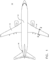
- aircraft 10 is shown with fuselage 12 and wings 14.
- Hat stiffeners are reinforcement structures often used to reinforce aircraft 10 structures such as a skin of fuselage 12, skin of wings 14 and or tail assembly 16.
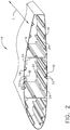
- a cross section along line 2-2 of wing 14 is shown which provides an example location of an employment of hat stiffeners which can be seen within wing 14.
- hat stiffeners 18 are shown which extend along length L of wing 14.
- Hat stiffener 18 includes hat portion 20 and flanges 22 extending from opposing sides of hat portion 20 along skin 24, in this example, of wing 14.
- hat stiffeners 18 are employed to reinforce such structural portions such as in this example skin 24 of wing 14. It is also beneficial in fabricating these structural portions to utilize co-cure securement such as between reinforcing hat stiffeners 18 and skin 24 of wing 14 to enhance the strength of an integrally formed skin 24 and hat stiffener 18 assembly of wing 14.
- a first embodiment A of method 36 for fabricating hat stiffeners 18, as set forth in FIG. 12 , having under-cut chamfered flanges 22 and which is co-cured with skin 24 of wing 14, can be seen in FIGS. 3-6 in this example.
- a second embodiment B of method 36 for fabricating hat stiffeners 18, as set forth in FIG. 12 , having under-cut chamfered flanges 22 and which is co-cured with skin 24, can be seen in FIGS. 7-11 , in this example.
- Mandrel 26 can be constructed of one of a number of shapes and in this example is a trapezoidal or rectangular shaped mandrel 26 with rounded or radial corners 28 is employed. Mandrel 26 can be constructed of a strong enough material such as metal, composite, rubber, silicone or ceramic material so as to support a plurality of plies of composite material without experiencing detrimental deformation to the shape of mandrel 26 through a curing process.
- second embodiment B of method 36 for fabricating hat stiffener 18 mandrel 30 is provided in FIG. 7 at (a).
- Mandrel 30 can be constructed of one of a number of shapes and in this example is a trapezoidal or rectangular shaped mandrel 30 with rounded or radial corners 32 having cutting notch 34 is employed.
- Mandrel 30, as mentioned for mandrel 26, can be constructed of a strong material such as metal, ceramic, composite material or a hollow and pressurized rubber or silicone material so as to support a plurality of plies of composite material without experiencing detrimental deformation to the shape of mandrel 30 up through a curing process.
- first embodiment A and second embodiment B Prior to discussing further detailed steps taken with respect to implementing each of first embodiment A and second embodiment B for method 36 for fabricating hat stiffeners 18, as seen in FIG. 12 which have under-cut and chamfered flanges 22, common steps for fabricating hat stiffener 18 to both first embodiment A and second embodiment B will be discussed. These steps provide an inexpensive and reliable approach in fabricating under-cut chamfered flanges for hat stiffeners 18.
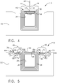
- method 36 for fabricating hat stiffener 18 includes step 37 for positioning two or more reinforcement fiber layers 38 about mandrel 26. With fiber layers 38 in position, method 36 includes step 39 for cutting through two more reinforcement fiber layers 38 with cutting tool 40 as seen in FIG. 4 resulting in a cut line 42 extending through fiber layers 38. With fiber layers 38 cut along a cut line 42, first stack of first end portions 44 of the two or more reinforcement fiber layers 38 is formed and second stack of second end portions 46 of the two or more reinforcement fiber layers 38 is also formed. Both first stack of first end portions 44 and second stack of second end portions 46 are in overlying relationship with respect to mandrel 26, as seen in FIG. 4 .
- Method 36 further includes step 41 for moving first stack of first end portions 44 and second stack of second end portions 46 of the two or more reinforcement fiber layers 38 out of overlying relationship with respect to mandrel 26, as seen for example in FIG. 5 .
- first stack of first end portions 44 and second stack of second end portions 46 of two or more reinforcement fiber layers 38 are positioned, as seen in FIG. 5 , forming fiber layers for flanges 22 of hat stiffener 18 which in this example will be constructed by way of infusion and curing and which will be discussed in further detail herein.
- flanges 22 will be chamfered and under-cut such that edges of resulting plies will be enclosed within completed flanges 22.
- method 36 for fabricating hat stiffener 18 includes step 37 of positioning two or more reinforcement fiber layers 38 about mandrel 30. With fiber layers 38 in position, method 36 includes step 39 of cutting through two more reinforcement fiber layers 38 with cutting tool 40 as seen in FIG. 8 resulting in a cut line 42 extending through fiber layers 38. With fiber layers 38 cut along cut line 42, first stack of first end portions 44 of the two or more reinforcement fiber layers 38 is formed and second stack of second end portions 46 of the two or more reinforcement fiber layers 38 is also formed. Both first stack of first end portions 44 and second stack of second end portions 46 are in overlying relationship with respect to mandrel 30, as seen in FIG. 8 .
- Method 36 further includes moving first stack of first end portions 44 and second stack of second end portions 46 of the two or more reinforcement fiber layers 38 out of overlying relationship with respect to mandrel 30, as seen for example in FIG. 9 .
- first stack of first end portions 44 and second stack of second end portions 46 of two or more reinforcement fiber layers 38 are positioned as seen in FIG. 9 , forming fiber layers for flanges 22 of hat stiffener 18 which in this example will be constructed by way of infusion and curing and which will be discussed in further detail herein.
- flanges 22 will be chamfered and under-cut such that edges of resulting plies will be enclosed within completed flanges 22.
- Reinforcement fiber layers can be arranged any one of a number of configurations including braided and filament wound and constructed of one of a number of materials such as carbon, glass, aramid and Kevlar fibers.
- a carbon fiber is used and is braided arrangement of the fibers is utilized with use of an automated braiding machine wherein the concentrically positioned layers can be braided directly onto mandrel 26.
- the braided layers can be braided separate and apart from mandrel 26 and then subsequently mounted onto mandrel 26.
- application of automated equipment can readily be applied for step 37 for positioning two or more reinforcement fiber layers 38 onto mandrel 26.
- step 37 for positioning the two or more reinforcement fiber layers 38 further includes positioning at least one additional reinforcement fiber layer 48, as seen at (b) - (d) in FIG. 3 .
- At least one additional reinforcement fiber layer 48 in this example includes a plurality of additional reinforcement fiber layers 48 which are positioned about mandrel 26 and, as seen at (d) in FIG. 3 , are positioned between the at least two or more reinforcement fiber layers 38 and mandrel 26.
- the at least one additional reinforcement fiber layer 48 is positioned about mandrel 26 as seen at (b) in FIG. 3 prior to positioning the two or more reinforcement fiber layers 38 about mandrel 26 as seen at (d) in FIG. 3 .
- Step 37 of positioning the two or more reinforcement fiber layers 38 further includes positioning cutting plate 50, as seen at (c) in FIG. 3 which results in cutting plate 50 being positioned in this example between the two or more reinforcement fiber layers 38 and the at least one additional reinforcement fiber layer 48 as seen at (d) in FIG. 3 .
- Cutting plate 50 is constructed of a strong material such as a metal or a composite that will receive an impact from cutting tool 40 and prevent any damage occurring to the at least one additional reinforcement layer 48 positioned underlying cutting plate 50.
- method 36 further includes in this example step 37 of positioning mandrel 26 with the two or more reinforcement fiber layers 38, cutting plate 50 and the at least one additional reinforcement fiber layer 48 into supporting tool 52.
- Method 36 further includes step 39 of cutting through the two or more reinforcement fiber layers 38 wherein cutting the two or more reinforcement fiber layers 38 is in alignment with cutting plate 50 as seen in FIG. 4 and shown with resulting cut line 42.
- step 41 for moving first stack of the first end portions 44 and the second stack of the second end portions 46 includes positioning portion 54 of first stack of first end portions 44 to extend in first direction 56 overlying first portion 58 of supporting tool 52.
- Step 41 further includes positioning portion 60 of second stack of second end portions 46 to extend in second direction 62 overlying second portion 64 of supporting tool 52, wherein first and second directions 56, 62 extend in opposite directions to one another.
- Step 41 for moving first stack of the first end portions 44 and the second stack of the second end portions 46 further includes positioning first end section 66 of at least one layer 68 of first stack of the first end portions 44 wherein first end section 66 extends in direction 69 in an angular relationship with respect to first direction 56.
- step 41 also includes positioning second end section 70 of the at least one layer 72 of second stack of the second end portions 46 in direction 73 in an angular relationship with respect to second direction 62. This angular extending of second end section 70 is facilitated by angular wall 77 of support tool 52.
- each reinforcement fiber layer within the at least two reinforcement fiber layers 38 being concentric to one another, as seen in FIGS. 3 at (d) and 4, the length of each reinforcement fiber layer increases as each layer is positioned further away from mandrel 26.
- the at least one layer 68 of first stack 44 was previously positioned furthest from mandrel 26 as part of layer 65, as seen in FIGS. 3 at (d) and 4, prior to cutting of the two or more reinforcement fiber layers 38.
- the at least one layer 68 in first stack 44 is part of the longest layer 65 within the two or more reinforcement fiber layers 38 and at least one layer 68 extends further along support tool 52 than layer 76 of first stack 44 which was part of the second longest layer 67 as seen in FIGS. 3 at (d) and 4.
- first stack 44 With the cut having been made through the two or more reinforcement fiber layers 38, first stack 44 is moved out of overlying relationship with respect to mandrel 26, as seen in FIG. 5 .
- the layers within first stack 44 bend around a center of radius 74 associated with curve 75 of supporting tool 52, as seen in FIG. 5 , and extend to form the chamfered edge 79 as described above.
- Reinforcement fiber layers within the two or more reinforcement fiber layers 38 are concentrically positioned with respect to one another, as seen in FIGS. 3 at (d) and 4 as described above.
- the length of each reinforcement fiber layer increases as each layer is positioned further away from mandrel 26.
- the at least one layer 72 of second stack 46 was previously positioned furthest from mandrel 26 as part of layer 65 as seen in FIGS. 3 at (d) and 4 prior to cutting of the two or more reinforcement fiber layers 38.
- the at least one layer 72 in second stack 46 is part of the longest layer 65 within the at least two reinforcement fiber layers 38 and extends further along support tool 52 than layer 78 of second stack 46 which was part of the second longest layer 67 as seen in FIGS. 3 at (d) and 4.
- second stack 46 is moved out of overlying relationship with respect to mandrel 26.
- the layers in second stack 46 bend around a center of radius 81 associated with curved angular wall 83 of supporting tool 52, as seen in FIG. 5 , and extend to form the chamfered edge 80 as described above.
- each of these have first and second end sections 66, 70 respectively which extend in directions 69 and 73 respectively.
- directions 69 and 73 extending in angular relationship with respect to first direction 56 and second direction 62 respectively and with the at least one layer 68 and at least one layer 72 extending longer along support tool 52 than other layers within first stack 44 and second stack 46 respectively, at least one layer 68 and at least one layer 72 enclose the remaining layers within first stack 44 and second stack 46 respectively.
- first stack 44 and second stack 46 are not exposed outside of edge 79 of first stack 44 or outside of edge 80 of second stack 46.
- This construction will prevent fibers from being exposed at edges of flanges 22 of hat stiffener 18 and prevent electrical static charge build-up occurring at either edge 79 or 80 of what will result as flanges 22 of hat stiffener 18.
- step 39 for cutting through the two or more reinforcement fiber layers 38 which can be implemented with an automated process, first stack of first end portions 44 and second stack of second end portions 46 are formed. Further included in method 36 is a step of removing cutting plate 50 which can be implemented so as to permit step 41 for moving first stack 44 and second stack 46 out of overlying relationship with respect to mandrel 26 can be implemented.
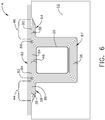
- the step of removing cutting plate 50 and step for moving first stack 44 and second stack 46 out of overlying relationship with respect to mandrel 26 can be facilitated in an automated process wherein an inflatable bladder (not shown) can be positioned beneath cutting plate 50, for example, such that the bladder is protected from cutting tool 40, and then inflated upon the completion of the cutting of the two or more reinforcement fiber layers 38 positioned above cutting plate 50. With the inflation of the bladder, cutting plate 50 can be removed away from support tool 52 and first and second stacks 44, 46 can be moved from overlying relationship with respect to mandrel 26 and positioned in overlying relationship with support tool 52 as seen in FIG.6 .
- an inflatable bladder (not shown) can be positioned beneath cutting plate 50, for example, such that the bladder is protected from cutting tool 40, and then inflated upon the completion of the cutting of the two or more reinforcement fiber layers 38 positioned above cutting plate 50.
- method 36 for fabricating hat stiffener 18 further includes, in this example, a step of positioning first radial filler member 82 adjacent to last layer 84 of the at least one additional reinforcement fiber layer 48 and adjacent to last layer 86 of first stack of first end portions 44 of two or more reinforcement fiber layers 38.
- last layer 84 is the reinforcement fiber layer within the at least one additional reinforcement fiber layer 48 positioned the furthest from mandrel 26 and last layer 86 of the first stack of first end portions 44 is the reinforcement fiber layer within first stack of first end portions 44 positioned furthest from first portion 58 of supporting tool 52.
- last layer 84 is the reinforcement fiber layer within the at least one additional reinforcement fiber layer 48 positioned the furthest from mandrel 26 and last layer 90 of the second stack of first end portions 46 is the reinforcement fiber layer of second stack of second end portions 46 of the two or more reinforcement fiber layers 38 positioned furthest from second portion 64 of supporting tool 52.
- Method 36 for fabricating hat stiffener 18 further includes a step of positioning at least one composite skin ply 92 in an overlying position related to the first stack of first end portions 44 of the two or more reinforcement fiber layers 38, second stack of second end portions 46 of the two or more reinforcement fiber layers 38, the first and second radial filler members 82, 88 and the last layer 84 of at least one additional reinforcement fiber layer 48.
- a plurality of layers are employed within the at least one additional reinforcement fiber layer 48 and a plurality of layers are employed within the at least one composite skin ply 92.
- a step of infusing a resin into within a preform assembly which includes: the first stack of first end portions 44 of the two or more reinforcement fiber layers 38, second stack of second end portions 46 of the two or more reinforcement fiber layers 38, a remainder 87 of the two or more reinforcement fiber layers 48 positioned between first stack of first end portions 44 and second stack of second end portions 46, the first and second radial filler members 82, 88 and the at least one additional reinforcement fiber layer 48.
- Method 36 for fabricating hat stiffener 18 also includes a step of co-curing the infused preform assembly which includes: first stack of first end portions 44 of the two or more reinforcement fiber layers 38, second stack of second end portions 46 of the two or more reinforcement fiber layers 38, the remainder 87 of the two or more reinforcement fiber layers 38 positioned between first stack of first end portions 44 and second stack of second end portions 46, the first and second radial filler members 82, 88, and the at least one additional reinforcement fiber layer 48, with the at least one composite skin ply 92, resulting in the fabrication of hat stiffener 18 with under-cut and chamfered flanges co-cured with at least one composite skin ply 92 of skin 24.
- steps of second embodiment B of method 36 for fabricating hat stiffener 18 can be seen.
- mandrel 30 with cutting notch 34 is shown in FIG. 7 at (a) and is employed in fabricating hat stiffener 18 with under-cut chamfered flanges 22.
- Step 37 of positioning two or more reinforcement fiber layers 38 about mandrel 30 is shown in FIG. 7 at (b).
- step 37 of positioning two or more reinforcement fiber layers 38 about mandrel 30 further includes positioning two or more reinforcement fiber layers 38 in overlying relationship to cutting notch 34 positioned on mandrel 30 is shown.
- a step of positioning mandrel 30 and the two or more reinforcement fiber layers into supporting tool 52 as seen in FIG. 8 .
- step 41 of moving first stack of the first end portions 44 and second stack of the second end portions 46 includes positioning portion 54 of first stack of first end portions 44 of two or more reinforcement fiber layers 38 to extend in first direction 56 overlying first portion 58 of supporting tool 52.
- step 41 further includes positioning portion 60 of second stack of second end portions 46 of two or more reinforcement fiber layers 38 to extend in second direction 62 overlying second portion 64 of supporting tool 52 wherein first and second directions 56, 62 extend in opposite directions to one another.
- step 41 of moving the first stack of first end portions 44 and the second stack of second end portions 46 of the two or more reinforcement fiber layers 38 further includes first end section 66 extending in direction 69 in an angular relationship with respect to first direction 56. This angular extending of first end section 66 is facilitated by angular wall 71 of support tool 52.
- step 41 also includes positioning second end section 70 of the at least one layer 72 of second stack of the second end portions 46 to extend in direction 73 in an angular relationship with respect to second direction 62. This angular extending of second end section 70 is facilitated by angular wall 77 of support tool 52.
- each reinforcement fiber layer within the at least two reinforcement fiber layers 38 being concentric to one another, as seen in FIG. 7 at (b), the length of each reinforcement fiber layer increases as each layer is positioned further away from mandrel 30.
- the at least one layer 68 of first stack 44 was previously positioned furthest from mandrel 30 as part of layer 65, as seen in FIG. 7 at (b), prior to cutting of the two or more reinforcement fiber layers 38.
- the at least one layer 68 in first stack 44 is part of the longest layer 65 within the two or more reinforcement fiber layers 38 and at least one layer 68 extends further along support tool 52 than layer 76 of first stack 44 which was part of the second longest layer 67 as seen in FIG. 7 at (b).
- first stack 44 As the two or more reinforcement fiber layers 38 were cut, and positioned within first stack 44, as seen in FIG. 9 , the layers positioned further above supporting tool 52 extend a shorter distance along support tool 52. As a result, a chamfer configuration is imparted to edge 79 of first stack 44 resulting in corresponding flange 22 to be constructed of hat stiffener 18 being chamfered.
- first stack 44 With the cut having been made through the two or more reinforcement fiber layers 38, first stack 44 is moved out of overlying relationship with respect to mandrel 26, as seen in FIG. 9 .
- the layers within first stack 44 bend around a center of radius 74 associated with curve 75 of supporting tool 52, as seen in FIG. 9 , and extend to form the chamfered edge 79 as described above.
- Reinforcement fiber layers within the two or more reinforcement fiber layers 38 are concentrically positioned with respect to one another, as seen in FIG. 7 at (b) as described above.
- the length of each reinforcement fiber layer increases as each layer is positioned further away from mandrel 30.
- the at least one layer 72 of second stack 46 was previously positioned furthest from mandrel 26 as part of layer 65 as seen in FIGS. 3 at (d) and 4 prior to cutting of the two or more reinforcement fiber layers 38.
- the at least one layer 72 in second stack 46 is part of the longest layer 65 within the at least two reinforcement fiber layers 38 and extends further along support tool 52 than layer 78 of second stack 46 which was part of the second longest layer 67 as seen in FIG. 7 at (d).
- second stack 46 is moved out of overlying relationship with respect to mandrel 30.
- the layers in second stack 46 bend around a center of radius 81 associated with curved angular wall 83 of supporting tool 52, as seen in FIG. 9 , and extend to form the chamfered edge 80 as described above.
- each of these have first and second end sections 66, 70 respectively which extend in directions 69 and 73 respectively.
- directions 69 and 73 extending in angular relationship with respect to first direction 56 and second direction 62 respectively and with the at least one layer 68 and at least one layer 72 extending longer along support tool 52 than other layers within first stack 44 and second stack 46 respectively, at least one layer 68 and at least one layer 72 enclose the remaining layers within first stack 44 and second stack 46 respectively.
- first stack 44 and second stack 46 are not exposed outside of edge 79 of first stack 44 or outside of edge 80 of second stack 46.
- This construction will prevent reinforcement fibers from being exposed at edges of flanges 22 of hat stiffener 18 and prevent electrical static charge build-up at either edges 79 or 80 of what will result as flanges 22 of hat stiffener 18.
- automated processes can be employed for both cutting two or more reinforcement fiber layers 38 with cutting tool 40 and moving first stack of first end portions 44 and second stack of second end portions 46 with an inflatable bladder as discussed earlier for first embodiment A.
- method 36 further includes in second embodiment B a step of removing mandrel 30 from supporting tool 52. Further included is a step of positioning at least one additional reinforcement fiber layer 48 about a second mandrel 94 (not shown).
- This application of at least one additional reinforcement fiber layer 48 can include as in this example automated braiding of at least one additional reinforcement fiber layer 48 onto second mandrel 94 or alternatively braiding at least one additional reinforcement fiber layer 48 separate and apart from second mandrel 94 and positioning the at least one additional reinforcement fiber layer 48 onto second mandrel 94.
- Different configurations and materials can be used in the construction of fiber layer 48 can be employed as was earlier discussed with respect to two or more reinforcement fiber layers 38.
- a plurality of reinforcement fiber layers are employed in the at least one additional reinforcement fiber layer 48.
- Method 36 further includes positioning second mandrel 94 with at least one additional reinforcement fiber layer 48 into supporting tool 52, as seen in FIG. 10 .
- method 36 further includes a step of positioning first radial filler member 82 adjacent to last layer 84 of the at least one additional reinforcement fiber layer 48 and adjacent to last layer 86 of first stack of the first end portions 44 of the two or more reinforcement fiber layers 38.
- Method 36 further includes a step of positioning second radial filler member 88 adjacent to last layer 84 of the at least one additional reinforcement fiber layer 48 and adjacent to last layer 90 of second stack of the second end portions 46 of the two or more reinforcement fiber layers 38.
- Method 36 further includes a step of positioning at least one composite skin ply 92 in an overlying position related to first stack of first end portions 44 of the two or more reinforcement fiber layers 38, the second stack of second end portions 46 of the two or more reinforcement fiber layers 38, the first and second radial filler members 82, 88 and last layer 84 of the at least one additional reinforcement fiber layer 48.
- Method 36 further includes a step of infusing a resin within a preform assembly which includes: at least one additional reinforcement fiber layer 48, the first and second radial filler members 82, 88, the first stack of first end portions 44 of the two or more reinforcement fiber layer 38, the second stack of the second end portions 46 of the two or more reinforcement fiber layers 38 and a remainder 87 of the two or more reinforcement fiber layers 38 positioned between first stack of the first end portions 44 and second stack of the second end portions 46.
- method 36 further includes co-curing the infused preform assembly which includes: at least one additional reinforcement fiber layer 48, the first and second radial filler members 82, 88, the first stack of the first end portions 44 of the two or more reinforcement fiber layers 38, the second stack of the second end portions 46 of the two or more reinforcement fiber layers 38, the remainder 87 of the two or more reinforcement fiber layers 38 positioned between first stack of the first end portions 44 and second stack of the second end portions 46, with the at least one composite skin ply 92.
Landscapes
- Engineering & Computer Science (AREA)
- Mechanical Engineering (AREA)
- Aviation & Aerospace Engineering (AREA)
- Chemical & Material Sciences (AREA)
- Composite Materials (AREA)
- Architecture (AREA)
- Civil Engineering (AREA)
- Structural Engineering (AREA)
- Moulding By Coating Moulds (AREA)
- Reinforced Plastic Materials (AREA)
- Casting Or Compression Moulding Of Plastics Or The Like (AREA)
Abstract
Description
- This disclosure relates to a method for fabricating a hat stiffener and more particularly to a hat stiffener having under-cut and chamfered flanges.
- Integrally stiffened structures such as hat shaped stiffeners and skin structures often require the hat shaped stiffeners to have chamfered flanges to reduce stress concentration at the interface with the skin being reinforced. Undercutting of the plies positioned in the flanges is employed to achieve a chamfered configuration and a configuration to enclose ply edges of the flanges. The enclosing of the ply edges encloses carbon fibers that are exposed at the edge of the plies positioned in the flanges. Fibers such as those constructed of carbon can experience a static charge buildup at the ply edges which then requires the need for sealing, bonding and grounding of the fiber ends so as to allow discharge of the static charge without creating unnecessary electrical transmission risk, particularly in the vicinity of fuel tanks.
- Chamfering un-cured composite stiffener flanges can be difficult to achieve in practice and particularly with respect to those that have shallow angles. This process can introduce significant recurring or non-recurring costs through specialized manufacturing processes and/or introduce limitations on the allowable geometry of the stiffener such as e.g. chamfer angle, pre-form thickness, curvature, pad-ups etc. Chamfering un-cured composite flanges of hat stiffeners is typically more difficult to achieve with dry materials compared with pre-impregnated materials and can introduce additional limitations on the allowable geometry such as minimum chamfer angle.
- Constructing the flanges to be square and not chamfered is not structurally efficient and may not be compatible with co-curing as a single integrated hat stiffener and skin construction. The square flange edge is also a poor design for facilitating electrical static buildup at the fiber ends that would be exposed on the square edge and would require sealing after fabrication.
- Staggering lay-up of individual plies, by way of manual or automated processes, of stiffener pre-forms using staggered ply drops can be used to create undercut chamfered flanges, however, application of these processes typically introduce either significant recurring and/or non-recurring costs. With using a manual process of ply by ply hand lay-up a high recurring cost is incurred. With utilizing an automated process which employs net trim limitation machines, there is a high non-recurring equipment cost which can also include limitations on achievable curvatures, ply ramps and other configurations for subsequent stiffener forming.
- Use of post-form trimming for undercutting the chamfer of pre-preg stiffeners has been demonstrated in production for very thin flanges where only a small number of plies are used in the layup. Replication of this process for dry reinforcements has not yet been demonstrated and is likely to be difficult for shallow chamfer angles due to a risk of fraying the edges of the dry fiber plies.
- There is a need for a method to provide chamfer undercut configurations for pre-form dry fibers in the manufacture of hat stiffeners used for stiffening reinforcement with respect to a skin structure. The method needs to provide a low cost to the fabrication of chamfered undercut flanges and be versatile to accommodate various needed thicknesses of flanges and various chamfer angles.
- An example includes a method for fabricating a hat stiffener which includes a step of positioning two or more reinforcement fiber layers about a mandrel. The method further includes a step of cutting through the two or more reinforcement fiber layers forming a first stack of first end portions of the two or more reinforcement fiber layers and a second stack of second end portions of the two or more reinforcement fiber layers wherein the first and second stacks are in overlying relationship with respect to the mandrel. In addition the method further includes moving the first stack of the first end portions and the second stack of the second end portions of the two or more reinforcement fiber layers out of overlying relationship with respect to the mandrel.
- The features, functions, and advantages that have been discussed can be achieved independently in various embodiments or may be combined in yet other embodiments further details of which can be seen with reference to the following description and drawings.
-
-
FIG. 1 is a top plan view of an aircraft; -
FIG. 2 is a perspective cross section view of a wing of the aircraft taken along line 2-2 inFIG. 1 ; -
FIG. 3 is a schematic cross section view of a mandrel showing successive steps within a first embodiment of a method for fabricating a hat stiffener including positioning reinforcement fiber layers about the mandrel and with the positioning a cutting plate between two adjacent reinforcement fiber layers completing a mandrel assembly; -
FIG. 4 is the mandrel assembly ofFIG. 3 positioned within a support tool for cutting; -
FIG. 5 is a view ofFIG. 4 wherein two or more reinforcement fiber layers have been cut forming a first stack of first end portions of reinforcement fiber layers and a second stack of second end portions of the reinforcement fiber layers wherein the first and second stacks have been moved out of overlying relationship with respect to the mandrel; -
FIG. 6 is a view ofFIG. 5 wherein the cutting plate has been removed and radial filler members and overlying composite skin plies have been installed; -
FIG. 7 is a schematic cross section view of another mandrel showing a step within a second embodiment of a method for fabricating a hat stiffener including positioning reinforcement fiber layers about the mandrel completing a mandrel assembly; -
FIG. 8 is the mandrel assembly ofFIG. 7 positioned within a support tool for cutting; -
FIG. 9 is the view ofFIG. 8 wherein two or more layers of reinforcement fibers have been cut into a first stack of first end portions of the reinforcement fiber layers and a second stack of second end portions of the reinforcement fiber layers the first and second stacks have been moved out of overlying relationship with respect to the mandrel; -
FIG. 10 is the view ofFIG. 9 wherein the mandrel ofFIG. 9 has been removed from the supporting tool and a second mandrel with additional reinforcement fiber layers positioned about the second mandrel has been inserted within the support tool; -
FIG. 11 is the view ofFIG. 10 wherein radial filler members and overlying composite skin plies have been installed; and -
FIG. 12 is a flow chart of a method for fabricating a hat stiffener. - As has been discussed with respect to integrally stiffened structures, such as a hat stiffener and skin structure, the flanges of hat stiffeners will experience less stress concentration with chamfered edges. Also, with enclosing edges of plies within the flanges of the hat stiffeners an improved performance occurs with respect to preventing electrical static charge build- up of fibers that would otherwise be exposed along the edges of the plies of the flanges. Without enclosing edges of the plies of the flanges of the hat stiffeners, reinforcement fibers are exposed along the edges of the plies which would require a need for sealing, bonding and grounding of the fiber ends so as to allow discharge without creating risk of electrical charge build-up. This is particularly important with respect to flanges of hat stiffeners that are located within the vicinity of fuel tanks.
- As a result, there is a need to produce hat stiffeners with under-cut chamfered flanges for purposes of providing less stress concentration and preventing electrical static charge build up along the edges of the plies of the flanges of hat stiffeners. In the interest of cost reductions, there is a need to provide a method which could be adapted to employ automated processes and reduce recurring manual costs and also a need not to require substantial equipment costs.
- In referring to
FIG. 1 ,aircraft 10 is shown withfuselage 12 andwings 14. Hat stiffeners are reinforcement structures often used to reinforceaircraft 10 structures such as a skin offuselage 12, skin ofwings 14 and ortail assembly 16. In this example, a cross section along line 2-2 ofwing 14 is shown which provides an example location of an employment of hat stiffeners which can be seen withinwing 14. In referring toFIG. 2 ,hat stiffeners 18 are shown which extend along length L ofwing 14.Hat stiffener 18 includeshat portion 20 andflanges 22 extending from opposing sides ofhat portion 20 alongskin 24, in this example, ofwing 14. - In fabricating structural portions of
aircraft 10, particularly structural portions which support substantial loadings,hat stiffeners 18 are employed to reinforce such structural portions such as in thisexample skin 24 ofwing 14. It is also beneficial in fabricating these structural portions to utilize co-cure securement such as between reinforcinghat stiffeners 18 andskin 24 ofwing 14 to enhance the strength of an integrally formedskin 24 and hat stiffener 18 assembly ofwing 14. - A first embodiment A of
method 36 for fabricatinghat stiffeners 18, as set forth inFIG. 12 , having under-cutchamfered flanges 22 and which is co-cured withskin 24 ofwing 14, can be seen inFIGS. 3-6 in this example. A second embodiment B ofmethod 36 for fabricatinghat stiffeners 18, as set forth inFIG. 12 , having under-cutchamfered flanges 22 and which is co-cured withskin 24, can be seen inFIGS. 7-11 , in this example. - With respect to first embodiment A of
method 36 for fabricatinghat stiffener 18mandrel 26 is provided inFIG. 3 at (a). Mandrel 26 can be constructed of one of a number of shapes and in this example is a trapezoidal or rectangularshaped mandrel 26 with rounded orradial corners 28 is employed. Mandrel 26 can be constructed of a strong enough material such as metal, composite, rubber, silicone or ceramic material so as to support a plurality of plies of composite material without experiencing detrimental deformation to the shape ofmandrel 26 through a curing process. With respect to second embodiment B ofmethod 36 for fabricatinghat stiffener 18mandrel 30 is provided inFIG. 7 at (a). Mandrel 30 can be constructed of one of a number of shapes and in this example is a trapezoidal or rectangularshaped mandrel 30 with rounded orradial corners 32 havingcutting notch 34 is employed.Mandrel 30, as mentioned formandrel 26, can be constructed of a strong material such as metal, ceramic, composite material or a hollow and pressurized rubber or silicone material so as to support a plurality of plies of composite material without experiencing detrimental deformation to the shape ofmandrel 30 up through a curing process. - Prior to discussing further detailed steps taken with respect to implementing each of first embodiment A and second embodiment B for
method 36 for fabricatinghat stiffeners 18, as seen inFIG. 12 which have under-cut and chamferedflanges 22, common steps for fabricating hat stiffener 18 to both first embodiment A and second embodiment B will be discussed. These steps provide an inexpensive and reliable approach in fabricating under-cut chamfered flanges forhat stiffeners 18. - With respect to first embodiment A, in referring to
FIGS. 3 at (d) and 12,method 36 for fabricatinghat stiffener 18 includesstep 37 for positioning two or morereinforcement fiber layers 38 aboutmandrel 26. Withfiber layers 38 in position,method 36 includesstep 39 for cutting through two morereinforcement fiber layers 38 withcutting tool 40 as seen inFIG. 4 resulting in acut line 42 extending throughfiber layers 38. Withfiber layers 38 cut along acut line 42, first stack offirst end portions 44 of the two or morereinforcement fiber layers 38 is formed and second stack ofsecond end portions 46 of the two or morereinforcement fiber layers 38 is also formed. Both first stack offirst end portions 44 and second stack ofsecond end portions 46 are in overlying relationship with respect tomandrel 26, as seen inFIG. 4 .Method 36 further includesstep 41 for moving first stack offirst end portions 44 and second stack ofsecond end portions 46 of the two or more reinforcement fiber layers 38 out of overlying relationship with respect tomandrel 26, as seen for example inFIG. 5 . As will be discussed in more detail herein, first stack offirst end portions 44 and second stack ofsecond end portions 46 of two or more reinforcement fiber layers 38 are positioned, as seen inFIG. 5 , forming fiber layers forflanges 22 ofhat stiffener 18 which in this example will be constructed by way of infusion and curing and which will be discussed in further detail herein. By way of employingmethod 36,flanges 22 will be chamfered and under-cut such that edges of resulting plies will be enclosed within completedflanges 22. - With respect to second method embodiment B, in referring to
FIGS. 7 at (b) and 12,method 36 for fabricatinghat stiffener 18 includesstep 37 of positioning two or more reinforcement fiber layers 38 aboutmandrel 30. With fiber layers 38 in position,method 36 includesstep 39 of cutting through two more reinforcement fiber layers 38 with cuttingtool 40 as seen inFIG. 8 resulting in acut line 42 extending through fiber layers 38. With fiber layers 38 cut alongcut line 42, first stack offirst end portions 44 of the two or more reinforcement fiber layers 38 is formed and second stack ofsecond end portions 46 of the two or more reinforcement fiber layers 38 is also formed. Both first stack offirst end portions 44 and second stack ofsecond end portions 46 are in overlying relationship with respect tomandrel 30, as seen inFIG. 8 .Method 36 further includes moving first stack offirst end portions 44 and second stack ofsecond end portions 46 of the two or more reinforcement fiber layers 38 out of overlying relationship with respect tomandrel 30, as seen for example inFIG. 9 . As will be discussed in more detail herein, first stack offirst end portions 44 and second stack ofsecond end portions 46 of two or more reinforcement fiber layers 38 are positioned as seen inFIG. 9 , forming fiber layers forflanges 22 ofhat stiffener 18 which in this example will be constructed by way of infusion and curing and which will be discussed in further detail herein. By way of employingmethod 36,flanges 22 will be chamfered and under-cut such that edges of resulting plies will be enclosed within completedflanges 22. - In referring to
FIGS. 3-6 and12 for first embodiment A formethod 36step 37 for positioning two or more reinforcement fiber layers 38 aboutmandrel 26 and further includes, in this example, two or more reinforcement fiber layers 38 being braided (not shown) and the two or more reinforcement fiber layers 38 being concentrically arranged aboutmandrel 26, as seen inFIG. 3 at (d). Reinforcement fiber layers can be arranged any one of a number of configurations including braided and filament wound and constructed of one of a number of materials such as carbon, glass, aramid and Kevlar fibers. In this example, a carbon fiber is used and is braided arrangement of the fibers is utilized with use of an automated braiding machine wherein the concentrically positioned layers can be braided directly ontomandrel 26. Alternatively, the braided layers can be braided separate and apart frommandrel 26 and then subsequently mounted ontomandrel 26. In either arrangement, application of automated equipment can readily be applied forstep 37 for positioning two or more reinforcement fiber layers 38 ontomandrel 26. - In further referring to
FIG. 3 , step 37 for positioning the two or more reinforcement fiber layers 38 further includes positioning at least one additionalreinforcement fiber layer 48, as seen at (b) - (d) inFIG. 3 . At least one additionalreinforcement fiber layer 48, in this example includes a plurality of additional reinforcement fiber layers 48 which are positioned aboutmandrel 26 and, as seen at (d) inFIG. 3 , are positioned between the at least two or more reinforcement fiber layers 38 andmandrel 26. In this example, the at least one additionalreinforcement fiber layer 48 is positioned aboutmandrel 26 as seen at (b) inFIG. 3 prior to positioning the two or more reinforcement fiber layers 38 aboutmandrel 26 as seen at (d) inFIG. 3 .Step 37 of positioning the two or more reinforcement fiber layers 38 further includespositioning cutting plate 50, as seen at (c) inFIG. 3 which results in cuttingplate 50 being positioned in this example between the two or more reinforcement fiber layers 38 and the at least one additionalreinforcement fiber layer 48 as seen at (d) inFIG. 3 . Cuttingplate 50 is constructed of a strong material such as a metal or a composite that will receive an impact from cuttingtool 40 and prevent any damage occurring to the at least oneadditional reinforcement layer 48 positioned underlying cuttingplate 50. - In referring to
FIGS. 4 and12 ,method 36 further includes in thisexample step 37 ofpositioning mandrel 26 with the two or more reinforcement fiber layers 38, cuttingplate 50 and the at least one additionalreinforcement fiber layer 48 into supportingtool 52.Method 36 further includesstep 39 of cutting through the two or more reinforcement fiber layers 38 wherein cutting the two or more reinforcement fiber layers 38 is in alignment with cuttingplate 50 as seen inFIG. 4 and shown with resulting cutline 42. - In referring to
FIGS. 5 and12 ,step 41 for moving first stack of thefirst end portions 44 and the second stack of thesecond end portions 46 includespositioning portion 54 of first stack offirst end portions 44 to extend infirst direction 56 overlyingfirst portion 58 of supportingtool 52.Step 41 further includes positioning portion 60 of second stack ofsecond end portions 46 to extend insecond direction 62 overlyingsecond portion 64 of supportingtool 52, wherein first andsecond directions Step 41 for moving first stack of thefirst end portions 44 and the second stack of thesecond end portions 46 further includes positioningfirst end section 66 of at least onelayer 68 of first stack of thefirst end portions 44 whereinfirst end section 66 extends indirection 69 in an angular relationship with respect tofirst direction 56. This angular extending offirst end section 66 is facilitated byangular wall 71 ofsupport tool 52. Similarly, step 41 also includes positioningsecond end section 70 of the at least onelayer 72 of second stack of thesecond end portions 46 indirection 73 in an angular relationship with respect tosecond direction 62. This angular extending ofsecond end section 70 is facilitated by angular wall 77 ofsupport tool 52. - With each reinforcement fiber layer within the at least two reinforcement fiber layers 38 being concentric to one another, as seen in
FIGS. 3 at (d) and 4, the length of each reinforcement fiber layer increases as each layer is positioned further away frommandrel 26. Thus, the at least onelayer 68 offirst stack 44 was previously positioned furthest frommandrel 26 as part oflayer 65, as seen inFIGS. 3 at (d) and 4, prior to cutting of the two or more reinforcement fiber layers 38. Thus the at least onelayer 68 infirst stack 44 is part of thelongest layer 65 within the two or more reinforcement fiber layers 38 and at least onelayer 68 extends further alongsupport tool 52 thanlayer 76 offirst stack 44 which was part of the secondlongest layer 67 as seen inFIGS. 3 at (d) and 4. As the two or more reinforcement fiber layers 38 were cut, and positioned withinfirst stack 44, as seen inFIG. 5 , the layers positioned further above supportingtool 52 extend a shorter distance alongsupport tool 52. As a result, a chamfer configuration is imparted to edge 79 offirst stack 44 resulting in correspondingflange 22 ofhat stiffener 18 being chamfered. - With the cut having been made through the two or more reinforcement fiber layers 38,
first stack 44 is moved out of overlying relationship with respect tomandrel 26, as seen inFIG. 5 . The layers withinfirst stack 44 bend around a center ofradius 74 associated withcurve 75 of supportingtool 52, as seen inFIG. 5 , and extend to form the chamferededge 79 as described above. - Reinforcement fiber layers within the two or more reinforcement fiber layers 38 are concentrically positioned with respect to one another, as seen in
FIGS. 3 at (d) and 4 as described above. The length of each reinforcement fiber layer increases as each layer is positioned further away frommandrel 26. Thus, the at least onelayer 72 ofsecond stack 46 was previously positioned furthest frommandrel 26 as part oflayer 65 as seen inFIGS. 3 at (d) and 4 prior to cutting of the two or more reinforcement fiber layers 38. Thus the at least onelayer 72 insecond stack 46 is part of thelongest layer 65 within the at least two reinforcement fiber layers 38 and extends further alongsupport tool 52 thanlayer 78 ofsecond stack 46 which was part of the secondlongest layer 67 as seen inFIGS. 3 at (d) and 4. As the two or more reinforcement fiber layers 38 were cut, and positioned withinsecond stack 46, as seen inFIG. 5 , the layers positioned further above supportingtool 52 extend a shorter distance alongsupport tool 52. As a result, a chamfer configuration is imparted to edge 80 ofsecond stack 46 resulting in correspondingflange 22 ofhat stiffener 18 being chamfered. - With the cut having been made through the at least two reinforcement fiber layers 38,
second stack 46 is moved out of overlying relationship with respect tomandrel 26. The layers insecond stack 46 bend around a center ofradius 81 associated with curvedangular wall 83 of supportingtool 52, as seen inFIG. 5 , and extend to form the chamferededge 80 as described above. - With respect to at least one
layer 68 in first stack offirst end portions 44 and at least onelayer 72 in the second stack ofsecond end portions 46, each of these, as described above, have first andsecond end sections directions directions first direction 56 andsecond direction 62 respectively and with the at least onelayer 68 and at least onelayer 72 extending longer alongsupport tool 52 than other layers withinfirst stack 44 andsecond stack 46 respectively, at least onelayer 68 and at least onelayer 72 enclose the remaining layers withinfirst stack 44 andsecond stack 46 respectively. As a result, fibers positioned in the enclosed layers offirst stack 44 andsecond stack 46 are not exposed outside ofedge 79 offirst stack 44 or outside ofedge 80 ofsecond stack 46. This construction will prevent fibers from being exposed at edges offlanges 22 ofhat stiffener 18 and prevent electrical static charge build-up occurring at eitheredge flanges 22 ofhat stiffener 18. - With
step 39 for cutting through the two or more reinforcement fiber layers 38, which can be implemented with an automated process, first stack offirst end portions 44 and second stack ofsecond end portions 46 are formed. Further included inmethod 36 is a step of removing cuttingplate 50 which can be implemented so as to permitstep 41 for movingfirst stack 44 andsecond stack 46 out of overlying relationship with respect tomandrel 26 can be implemented. In this example, the step of removing cuttingplate 50 and step for movingfirst stack 44 andsecond stack 46 out of overlying relationship with respect tomandrel 26 can be facilitated in an automated process wherein an inflatable bladder (not shown) can be positioned beneath cuttingplate 50, for example, such that the bladder is protected from cuttingtool 40, and then inflated upon the completion of the cutting of the two or more reinforcement fiber layers 38 positioned above cuttingplate 50. With the inflation of the bladder, cuttingplate 50 can be removed away fromsupport tool 52 and first andsecond stacks mandrel 26 and positioned in overlying relationship withsupport tool 52 as seen inFIG.6 . - With cutting
plate 50 removed and first stack offirst end portions 44 and second stack ofsecond end portions 46 moved into overlying relationship with support tool as seen inFIG. 6 ,method 36 for fabricatinghat stiffener 18 further includes, in this example, a step of positioning firstradial filler member 82 adjacent tolast layer 84 of the at least one additionalreinforcement fiber layer 48 and adjacent tolast layer 86 of first stack offirst end portions 44 of two or more reinforcement fiber layers 38. In this example,last layer 84 is the reinforcement fiber layer within the at least one additionalreinforcement fiber layer 48 positioned the furthest frommandrel 26 andlast layer 86 of the first stack offirst end portions 44 is the reinforcement fiber layer within first stack offirst end portions 44 positioned furthest fromfirst portion 58 of supportingtool 52. In this example, further included is a step of positioning secondradial filler member 88 adjacent tolast layer 84 of the at least one additionalreinforcement fiber layer 48 and adjacent tolast layer 90 of the second stack ofsecond end portions 46 of two or more reinforcement fiber layers 38. In this example,last layer 84, as mentioned above, is the reinforcement fiber layer within the at least one additionalreinforcement fiber layer 48 positioned the furthest frommandrel 26 andlast layer 90 of the second stack offirst end portions 46 is the reinforcement fiber layer of second stack ofsecond end portions 46 of the two or more reinforcement fiber layers 38 positioned furthest fromsecond portion 64 of supportingtool 52. -
Method 36 for fabricatinghat stiffener 18 further includes a step of positioning at least one composite skin ply 92 in an overlying position related to the first stack offirst end portions 44 of the two or more reinforcement fiber layers 38, second stack ofsecond end portions 46 of the two or more reinforcement fiber layers 38, the first and secondradial filler members last layer 84 of at least one additionalreinforcement fiber layer 48. In this example, a plurality of layers are employed within the at least one additionalreinforcement fiber layer 48 and a plurality of layers are employed within the at least onecomposite skin ply 92. - Further included in
method 36 is a step of infusing a resin into within a preform assembly which includes: the first stack offirst end portions 44 of the two or more reinforcement fiber layers 38, second stack ofsecond end portions 46 of the two or more reinforcement fiber layers 38, aremainder 87 of the two or more reinforcement fiber layers 48 positioned between first stack offirst end portions 44 and second stack ofsecond end portions 46, the first and secondradial filler members reinforcement fiber layer 48. -
Method 36 for fabricatinghat stiffener 18 also includes a step of co-curing the infused preform assembly which includes: first stack offirst end portions 44 of the two or more reinforcement fiber layers 38, second stack ofsecond end portions 46 of the two or more reinforcement fiber layers 38, theremainder 87 of the two or more reinforcement fiber layers 38 positioned between first stack offirst end portions 44 and second stack ofsecond end portions 46, the first and secondradial filler members reinforcement fiber layer 48, with the at least onecomposite skin ply 92, resulting in the fabrication ofhat stiffener 18 with under-cut and chamfered flanges co-cured with at least one composite skin ply 92 ofskin 24. - In referring to
FIGS. 7 - 11 , steps of second embodiment B ofmethod 36 for fabricatinghat stiffener 18 can be seen. As earlier discussed,mandrel 30 with cuttingnotch 34 is shown inFIG. 7 at (a) and is employed in fabricatinghat stiffener 18 with under-cut chamferedflanges 22.Step 37 of positioning two or more reinforcement fiber layers 38 aboutmandrel 30 is shown inFIG. 7 at (b). As seen inFIG. 7 at (b), step 37 of positioning two or more reinforcement fiber layers 38 aboutmandrel 30 further includes positioning two or more reinforcement fiber layers 38 in overlying relationship to cuttingnotch 34 positioned onmandrel 30 is shown. Additionally included is a step of positioningmandrel 30 and the two or more reinforcement fiber layers into supportingtool 52, as seen inFIG. 8 . - With completion of
step 39 of cutting through two or more reinforcement fiber layers 38 with cuttingtool 40, cutline 42 through fiber layers 38, as shown inFIG. 8 , first stack offirst end portions 44 of two or more reinforcement fiber layers 38 and second stack ofsecond end portions 46 of two or more reinforcement fiber layers 38 are formed and which are in overlying relationship with respect tomandrel 30. In referring toFIG. 9 , step 41 of moving first stack of thefirst end portions 44 and second stack of thesecond end portions 46 includespositioning portion 54 of first stack offirst end portions 44 of two or more reinforcement fiber layers 38 to extend infirst direction 56 overlyingfirst portion 58 of supportingtool 52.Step 41 further includes positioning portion 60 of second stack ofsecond end portions 46 of two or more reinforcement fiber layers 38 to extend insecond direction 62 overlyingsecond portion 64 of supportingtool 52 wherein first andsecond directions - In referring to
FIG. 9 , step 41 of moving the first stack offirst end portions 44 and the second stack ofsecond end portions 46 of the two or more reinforcement fiber layers 38 further includesfirst end section 66 extending indirection 69 in an angular relationship with respect tofirst direction 56. This angular extending offirst end section 66 is facilitated byangular wall 71 ofsupport tool 52. Similarly, step 41 also includes positioningsecond end section 70 of the at least onelayer 72 of second stack of thesecond end portions 46 to extend indirection 73 in an angular relationship with respect tosecond direction 62. This angular extending ofsecond end section 70 is facilitated by angular wall 77 ofsupport tool 52. - With each reinforcement fiber layer within the at least two reinforcement fiber layers 38 being concentric to one another, as seen in
FIG. 7 at (b), the length of each reinforcement fiber layer increases as each layer is positioned further away frommandrel 30. Thus, the at least onelayer 68 offirst stack 44 was previously positioned furthest frommandrel 30 as part oflayer 65, as seen inFIG. 7 at (b), prior to cutting of the two or more reinforcement fiber layers 38. Thus the at least onelayer 68 infirst stack 44 is part of thelongest layer 65 within the two or more reinforcement fiber layers 38 and at least onelayer 68 extends further alongsupport tool 52 thanlayer 76 offirst stack 44 which was part of the secondlongest layer 67 as seen inFIG. 7 at (b). As the two or more reinforcement fiber layers 38 were cut, and positioned withinfirst stack 44, as seen inFIG. 9 , the layers positioned further above supportingtool 52 extend a shorter distance alongsupport tool 52. As a result, a chamfer configuration is imparted to edge 79 offirst stack 44 resulting in correspondingflange 22 to be constructed ofhat stiffener 18 being chamfered. - With the cut having been made through the two or more reinforcement fiber layers 38,
first stack 44 is moved out of overlying relationship with respect tomandrel 26, as seen inFIG. 9 . The layers withinfirst stack 44 bend around a center ofradius 74 associated withcurve 75 of supportingtool 52, as seen inFIG. 9 , and extend to form the chamferededge 79 as described above. - Reinforcement fiber layers within the two or more reinforcement fiber layers 38 are concentrically positioned with respect to one another, as seen in
FIG. 7 at (b) as described above. The length of each reinforcement fiber layer increases as each layer is positioned further away frommandrel 30. Thus, the at least onelayer 72 ofsecond stack 46 was previously positioned furthest frommandrel 26 as part oflayer 65 as seen inFIGS. 3 at (d) and 4 prior to cutting of the two or more reinforcement fiber layers 38. Thus the at least onelayer 72 insecond stack 46 is part of thelongest layer 65 within the at least two reinforcement fiber layers 38 and extends further alongsupport tool 52 thanlayer 78 ofsecond stack 46 which was part of the secondlongest layer 67 as seen inFIG. 7 at (d). As the two or more reinforcement fiber layers 38 were cut, and positioned withinsecond stack 46, as seen inFIG. 9 , the layers positioned further above supportingtool 52 extend a shorter distance alongsupport tool 52. As a result, a chamfer configuration is imparted to edge 80 ofsecond stack 46 resulting in correspondingflange 22 to be constructed ofhat stiffener 18 being chamfered. - With the cut having been made through the at least two reinforcement fiber layers 38,
second stack 46 is moved out of overlying relationship with respect tomandrel 30. The layers insecond stack 46 bend around a center ofradius 81 associated with curvedangular wall 83 of supportingtool 52, as seen inFIG. 9 , and extend to form the chamferededge 80 as described above. - With respect to at least one
layer 68 in first stack offirst end portions 44 and at least onelayer 72 in the second stack ofsecond end portions 46, each of these, as described above, have first andsecond end sections directions directions first direction 56 andsecond direction 62 respectively and with the at least onelayer 68 and at least onelayer 72 extending longer alongsupport tool 52 than other layers withinfirst stack 44 andsecond stack 46 respectively, at least onelayer 68 and at least onelayer 72 enclose the remaining layers withinfirst stack 44 andsecond stack 46 respectively. As a result, fibers positioned in the enclosed layers offirst stack 44 andsecond stack 46 are not exposed outside ofedge 79 offirst stack 44 or outside ofedge 80 ofsecond stack 46. This construction will prevent reinforcement fibers from being exposed at edges offlanges 22 ofhat stiffener 18 and prevent electrical static charge build-up at eitheredges flanges 22 ofhat stiffener 18. - In second embodiment B of
method 36, automated processes can be employed for both cutting two or more reinforcement fiber layers 38 with cuttingtool 40 and moving first stack offirst end portions 44 and second stack ofsecond end portions 46 with an inflatable bladder as discussed earlier for first embodiment A. - In referring to
FIG. 9 ,method 36 further includes in second embodiment B a step of removingmandrel 30 from supportingtool 52. Further included is a step of positioning at least one additionalreinforcement fiber layer 48 about a second mandrel 94 (not shown). This application of at least one additionalreinforcement fiber layer 48 can include as in this example automated braiding of at least one additionalreinforcement fiber layer 48 ontosecond mandrel 94 or alternatively braiding at least one additionalreinforcement fiber layer 48 separate and apart fromsecond mandrel 94 and positioning the at least one additionalreinforcement fiber layer 48 ontosecond mandrel 94. Different configurations and materials can be used in the construction offiber layer 48 can be employed as was earlier discussed with respect to two or more reinforcement fiber layers 38. In this example, a plurality of reinforcement fiber layers are employed in the at least one additionalreinforcement fiber layer 48.Method 36 further includes positioningsecond mandrel 94 with at least one additionalreinforcement fiber layer 48 into supportingtool 52, as seen inFIG. 10 . - In referring to
FIG. 11 ,method 36 further includes a step of positioning firstradial filler member 82 adjacent tolast layer 84 of the at least one additionalreinforcement fiber layer 48 and adjacent tolast layer 86 of first stack of thefirst end portions 44 of the two or more reinforcement fiber layers 38.Method 36 further includes a step of positioning secondradial filler member 88 adjacent tolast layer 84 of the at least one additionalreinforcement fiber layer 48 and adjacent tolast layer 90 of second stack of thesecond end portions 46 of the two or more reinforcement fiber layers 38. -
Method 36 further includes a step of positioning at least one composite skin ply 92 in an overlying position related to first stack offirst end portions 44 of the two or more reinforcement fiber layers 38, the second stack ofsecond end portions 46 of the two or more reinforcement fiber layers 38, the first and secondradial filler members last layer 84 of the at least one additionalreinforcement fiber layer 48.Method 36 further includes a step of infusing a resin within a preform assembly which includes: at least one additionalreinforcement fiber layer 48, the first and secondradial filler members first end portions 44 of the two or morereinforcement fiber layer 38, the second stack of thesecond end portions 46 of the two or more reinforcement fiber layers 38 and aremainder 87 of the two or more reinforcement fiber layers 38 positioned between first stack of thefirst end portions 44 and second stack of thesecond end portions 46. Once the infusion of resin is complete,method 36 further includes co-curing the infused preform assembly which includes: at least one additionalreinforcement fiber layer 48, the first and secondradial filler members first end portions 44 of the two or more reinforcement fiber layers 38, the second stack of thesecond end portions 46 of the two or more reinforcement fiber layers 38, theremainder 87 of the two or more reinforcement fiber layers 38 positioned between first stack of thefirst end portions 44 and second stack of thesecond end portions 46, with the at least onecomposite skin ply 92. - Further, the disclosure comprises examples according to the following clauses:
- Clause 1. A method for fabricating a hat stiffener, comprising steps of:
- positioning two or more reinforcement fiber layers about a mandrel;
- cutting through the two or more reinforcement fiber layers forming a first stack of first end portions of the two or more reinforcement fiber layers and a second stack of second end portions of the two or more reinforcement fiber layers wherein the first and second stacks are in overlying relationship with respect to the mandrel; and
- moving the first stack of the first end portions and the second stack of the second end portions of the two or more reinforcement fiber layers out of overlying relationship with respect to the mandrel.
-
Clause 2. The method for fabricating of clause 1, the step of positioning the two or more reinforcement fiber layers about the mandrel further includes the two or more reinforcement fiber layers being braided and the two or more reinforcement fiber layers being concentrically arranged about the mandrel. - Clause 3. The method for fabricating of
clause 1 or 2, wherein:- the step of positioning the two or more reinforcement fiber layers further includes positioning at least one additional reinforcement fiber layer about the mandrel positioned between the at least two or more reinforcement fiber layers and the mandrel; and
- the step of positioning the two or more reinforcement fiber layers further includes positioning a cutting plate positioned between the at least two or more reinforcement fiber layers and the at least one additional reinforcement fiber layer.
- Clause 4. The method for fabricating of clause 3, further including a step of positioning the mandrel with the two or more reinforcement fiber layers, cutting plate and the at least one additional reinforcement fiber layer into a supporting tool.
- Clause 5. The method for fabricating of clause 4, wherein the step of cutting through the two or more reinforcement fiber layers includes cutting the two or more reinforcement fiber layers in alignment with the cutting plate.
- Clause 6. The method for fabricating of clause 5, the step of moving the first stack of the first end portions and the second stack of the second end portions includes:
- a step of positioning a portion of the first stack of the first end portions to extend in a first direction overlying a first portion of the supporting tool; and
- a step of positioning a portion of the second stack of the second end portions to extend in a second direction overlying a second portion of the supporting tool, wherein the first and second directions extend in opposite directions to one another.
- Clause 7. The method for fabricating of clause 6, further including a step of removing the cutting plate.
- Clause 8. The method for fabricating of clause 6 or 7, the step of moving the first stack of the first end portions and the second stack of the second end portions, further includes:
- a step of positioning a first end section of at least one layer of the first stack of the first end portions in an angular relationship with respect to the first direction; and
- a step of positioning a second end section of at least one layer of the second stack of the second end portions in an angular relationship with respect to the second direction.
- Clause 9. The method for fabricating of any of clauses 6 to 8, further including:
- a step of positioning a first radial filler member adjacent to a last layer of the at least one additional reinforcement fiber layer and adjacent to a last layer of the first stack of first end portions of the two or more reinforcement fiber layers; and
- a step of positioning a second radial filler member adjacent to the last layer of the at least one additional reinforcement fiber layer and adjacent to a last layer of the second stack of the second end portions of the two or more reinforcement fiber layers.
-
Clause 10. The method for fabricating of clause 9, further including:- a step of positioning at least one composite skin ply in an overlying position related to the first stack of first end portions of the two or more reinforcement fiber layers, the second stack of second end portions of the two or more reinforcement fiber layers, the first and second radial filler members and the last layer of the at least one additional reinforcement fiber layer;
- a step of infusing a resin within a preform assembly including the first stack of first end portions of the two or more reinforcement fiber layers, second stack of second end portions of the two or more reinforcement fiber layers, a remainder of the two or more reinforcement fiber layers positioned between the first stack of the first end portions and the second stack of the second end portions, the first and second radial filler members and the at least one additional reinforcement fiber layer; and
- a step of co-curing the infused preform assembly including first stack of first end portions of the two or more reinforcement fiber layers, second stack of second end portions of the two or more reinforcement fiber layers, the remainder of the two or more reinforcement fiber layers positioned between the first stack of the first end portions and the second stack of the second end portions, the first and second radial filler members and the at least one additional reinforcement fiber layer with the at least one composite skin ply.
- Clause 11. The method for fabricating of any of clauses 1 to 10, the step of positioning two or more reinforcement fiber layers on the mandrel includes positioning the two or more reinforcement fiber layers in overlying relationship to a cutting notch positioned on the mandrel.
-
Clause 12. The method for fabricating of clause 11, further including a step of positioning the mandrel and the two or more reinforcement fiber layers into a supporting tool. - Clause 13. The method for fabricating of
clause 12, the step of moving the first stack of the first end portions and the second stack of the second end portions includes:- a step of positioning a portion of the first stack of first end portions of the two or more reinforcement fiber layers to extend in a first direction overlying a first portion of the supporting tool; and
- a step of positioning a portion of the second stack of second end portions of the two or more reinforcement fiber layers to extend in a second direction overlying a second portion of the supporting tool wherein the first and second directions extend in opposite directions to one another.
-
Clause 14. The method for fabricating of clause 13, the step of moving the first stack of first end portions and the second stack of second end portions of the two or more reinforcement fiber layers further includes:- a step of positioning a first end section of at least one layer of the first stack of first end portions in an angular relationship with respect to the first direction; and
- a step of positioning a second end section of at least one layer of the second stack of second end portions in an angular relationship with respect to the second direction.
- Clause 15. The method for fabricating of any of clauses 1 to 14, further including a step of removing the mandrel from a supporting tool.
-
Clause 16. The method for fabricating of clause 15, further including a step of positioning at least one additional reinforcement fiber layer about a second mandrel. - Clause 17. The method for fabricating of
clause 16, further including a step of positioning the second mandrel with the at least one additional reinforcement fiber layer into the supporting tool. -
Clause 18. The method for fabricating of clause 17, further including:- a step of positioning a first radial filler member adjacent to a last layer of the at least one additional reinforcement fiber layer and adjacent to a last layer of the first stack of the first end portions of the two or more reinforcement fiber layers; and
- a step of positioning a second radial filler member adjacent to the last layer of the at least one additional reinforcement fiber layer and adjacent to a last layer of the second stack of the second end portions of the two or more reinforcement fiber layers.
- Clause 19. The method for fabricating of
clause 18, further including a step of positioning at least one composite skin ply in an overlying position related to first stack of first end portions of the two or more reinforcement fiber layers, the second stack of second end portions of the two or more reinforcement fiber layers, the first and second radial filler members and the last layer of the at least one additional reinforcement fiber layer. -
Clause 20. The method for fabricating of clause 19, further including a step of:- infusing a resin within a preform assembly including the at least one additional reinforcement fiber layer, the first and second radial filler members, the first stack of first end portions of the two or more reinforcement fiber layers, the second stack of the second end portions of the two or more reinforcement fiber layers and a remainder of the two or more reinforcement fiber layers positioned between the first stack of the first end portions and the second stack of the second end portions; and
- co-curing the infused preform assembly including the at least one additional reinforcement fiber layer, the first and second radial filler members, the first stack of the first end portions of the two or more reinforcement fiber layers and the second stack of the second end portions of the two or more reinforcement fiber layers and the remainder of the two or more reinforcement fiber layers positioned between the first stack of the first end portions and the second stack of the second end portions, with the at least one composite skin ply.
- While various embodiments have been described above, this disclosure is not intended to be limited thereto. Variations can be made to the disclosed embodiments that are still within the scope of the appended claims.
Claims (15)
- A method (36) for fabricating a hat stiffener (18), comprising steps of:positioning (37) two or more reinforcement fiber layers (38) about a mandrel (26);cutting (39) through the two or more reinforcement fiber layers (38) forming a first stack of first end portions (44) of the two or more reinforcement fiber layers (38) and a second stack of second end portions (46) of the two or more reinforcement fiber layers (38) wherein the first and second stacks are in overlying relationship with respect to the mandrel (26); andmoving (41) the first stack of the first end portions (44) and the second stack of the second end portions (46) of the two or more reinforcement fiber layers (38) out of overlying relationship with respect to the mandrel (26).
- The method for fabricating of claim 1, the step of positioning (37) the two or more reinforcement fiber layers (38) about the mandrel (26) further includes the two or more reinforcement fiber layers (38) being braided and the two or more reinforcement fiber layers (38) being concentrically arranged about the mandrel (26).
- The method for fabricating of claims 1-2, wherein:the step of positioning (37) the two or more reinforcement fiber layers (38) further includes positioning at least one additional reinforcement fiber layer (48) about the mandrel (26) positioned between the at least two or more reinforcement fiber layers (38) and the mandrel (26); andthe step of positioning (37) the two or more reinforcement fiber layers (38) further includes positioning a cutting plate (50) positioned between the at least two or more reinforcement fiber layers (38) and the at least one additional reinforcement fiber layer (48), optionally further including a step of positioning the mandrel (26) with the two or more reinforcement fiber layers (38), cutting plate (50) and the at least one additional reinforcement fiber layer (48) into a supporting tool (52).
- The method for fabricating of claim 3, wherein the step of cutting through the two or more reinforcement fiber layers (38) includes cutting the two or more reinforcement fiber layers (38) in alignment with the cutting plate (50).
- The method for fabricating of claim 4, the step of moving the first stack of the first end portions (44) and the second stack of the second end portions (46) includes:a step of positioning a portion (54) of the first stack of the first end portions (44) to extend in a first direction (56) overlying a first portion (58) of the supporting tool (52); anda step of positioning a portion (60) of the second stack of the second end portions (46) to extend in a second direction (62) overlying a second portion (64) of the supporting tool (52), wherein the first and second directions (56, 62) extend in opposite directions to one another, and optionally further including a step of removing the cutting plate (50).
- The method for fabricating of claims 4-5, the step of moving the first stack of the first end portions (44) and the second stack of the second end portions (46), further includes:a step of positioning a first end section (66) of at least one layer (68)of the first stack of the first end portions (66) in an angular relationship with respect to the first direction (56); anda step of positioning a second end section (70) of at least one layer (72) of the second stack of the second end portions (46) in an angular relationship with respect to the second direction (62).
- The method for fabricating of claims 4-6, further including:a step of positioning a first radial filler member (82) adjacent to a last layer (84) of the at least one additional reinforcement fiber layer (48) and adjacent to a last layer (86) of the first stack of first end portions (44) of the two or more reinforcement fiber layers (38); anda step of positioning a second radial filler member (88) adjacent to the last layer (84) of the at least one additional reinforcement fiber layer (48) and adjacent to a last layer (90) of the second stack of the second end portions (46) of the two or more reinforcement fiber layers (38).
- The method for fabricating of claim 7, further including:a step of positioning at least one composite skin ply (92) in an overlying position related to the first stack of first end portions (44) of the two or more reinforcement fiber layers (38), the second stack of second end portions (46) of the two or more reinforcement fiber layers (38), the first and second radial filler members (82, 88) and the last layer (84) of the at least one additional reinforcement fiber layer (48);a step of infusing a resin within a preform assembly including the first stack of first end portions (44) of the two or more reinforcement fiber layers (38), second stack of second end portions (46) of the two or more reinforcement fiber layers (38), a remainder of the two or more reinforcement fiber layers (38) positioned between the first stack of the first end portions (44) and the second stack of the second end portions (46), the first and second radial filler members (82, 88) and the at least one additional reinforcement fiber layer (48); anda step of co-curing the infused preform assembly including first stack of first end portions (44) of the two or more reinforcement fiber layers (38), second stack of second end portions (46) of the two or more reinforcement fiber layers (38), the remainder of the two or more reinforcement fiber layers (38) positioned between the first stack of the first end portions (44) and the second stack of the second end portions (46), the first and second radial filler members (82, 88) and the at least one additional reinforcement fiber layer (48) with the at least one composite skin ply (92).
- The method for fabricating of claims 1-8, the step of positioning two or more reinforcement fiber layers (38) on the mandrel (26) includes positioning the two or more reinforcement fiber layers (38) in overlying relationship to a cutting notch (34) positioned on the mandrel (26), and optionally
further including a step of positioning the mandrel (26) and the two or more reinforcement fiber layers (38) into a supporting tool (52). - The method for fabricating of claim 9, the step of moving the first stack of the first end portions (44) and the second stack of the second end portions (46) includes:a step of positioning a portion of the first stack of first end portions (44) of the two or more reinforcement fiber layers (38) to extend in a first direction (56) overlying a first portion (58) of the supporting tool (52); anda step of positioning a portion of the second stack of second end portions (46) of the two or more reinforcement fiber layers (38) to extend in a second direction (62) overlying a second portion (64) of the supporting tool (52) wherein the first and second directions (56, 62) extend in opposite directions to one another.
- The method for fabricating of claim 10, the step of moving the first stack of first end portions (44) and the second stack of second end portions (46) of the two or more reinforcement fiber layers (38) further includes:a step of positioning a first end section (66) of at least one layer (68) of the first stack of first end portions (44) in an angular relationship with respect to the first direction (56); anda step of positioning a second end section (70) of at least one layer of the second stack of second end portions (46) in an angular relationship with respect to the second direction (62).
- The method for fabricating of claims 1-11, further including a step of removing the mandrel (26) from a supporting tool (52).
- The method for fabricating of claim 12, further including a step of positioning at least one additional reinforcement fiber layer (48) about a second mandrel (94), and optionally further including a step of positioning the second mandrel (94) with the at least one additional reinforcement fiber layer (48) into the supporting tool (52).
- The method for fabricating of claim 13, further including:a step of positioning a first radial filler member (82) adjacent to a last layer (84) of the at least one additional reinforcement fiber layer (48) and adjacent to a last layer (86) of the first stack of the first end portions (44) of the two or more reinforcement fiber layers (38); anda step of positioning a second radial filler member (88) adjacent to the last layer (84) of the at least one additional reinforcement fiber layer (48) and adjacent to a last layer (90) of the second stack of the second end portions (46) of the two or more reinforcement fiber layers (38), and optionallyfurther including a step of positioning at least one composite skin ply (92) in an overlying position related to first stack of first end portions (44) of the two or more reinforcement fiber layers (38), the second stack of second end portions (46) of the two or more reinforcement fiber layers (38), the first and second radial filler members (82, 88) and the last layer (84) of the at least one additional reinforcement fiber layer (48).
- The method for fabricating of claim 14, further including a step of:infusing a resin within a preform assembly including the at least one additional reinforcement fiber layer (48), the first and second radial filler members (82, 88), the first stack of first end portions (44) of the two or more reinforcement fiber layers (38), the second stack of the second end portions (46) of the two or more reinforcement fiber layers (38) and a remainder of the two or more reinforcement fiber layers (38) positioned between the first stack of the first end portions (44) and the second stack of the second end portions (46); andco-curing the infused preform assembly including the at least one additional reinforcement fiber layer (48), the first and second radial filler members (82, 88), the first stack of the first end portions (44) of the two or more reinforcement fiber layers (38) and the second stack of the second end portions (46) of the two or more reinforcement fiber layers (38) and the remainder of the two or more reinforcement fiber layers (38) positioned between the first stack of the first end portions (44) and the second stack of the second end portions (46), with the at least one composite skin ply (92).
Applications Claiming Priority (1)
| Application Number | Priority Date | Filing Date | Title |
|---|---|---|---|
| US15/787,967 US10717240B2 (en) | 2017-10-19 | 2017-10-19 | Method for making a hat stiffener pre-form with under-cut chamfered flange |
Publications (2)
| Publication Number | Publication Date |
|---|---|
| EP3473416A1 true EP3473416A1 (en) | 2019-04-24 |
| EP3473416B1 EP3473416B1 (en) | 2024-06-26 |
Family
ID=63077722
Family Applications (1)
| Application Number | Title | Priority Date | Filing Date |
|---|---|---|---|
| EP18185680.8A Active EP3473416B1 (en) | 2017-10-19 | 2018-07-26 | Method for making a hat stiffener pre-form with under-cut chamfered flange |
Country Status (5)
| Country | Link |
|---|---|
| US (1) | US10717240B2 (en) |
| EP (1) | EP3473416B1 (en) |
| JP (1) | JP7131998B2 (en) |
| CN (1) | CN109676954B (en) |
| AU (1) | AU2018205159B2 (en) |
Families Citing this family (3)
| Publication number | Priority date | Publication date | Assignee | Title |
|---|---|---|---|---|
| EP3718758B1 (en) * | 2017-11-27 | 2024-10-09 | Nitto Denko Corporation | Reinforcement structure and producing method of reinforcement structure |
| DE102019108769A1 (en) * | 2019-04-03 | 2020-10-08 | Airbus Operations Gmbh | Stiffened flat component made of polymer material and method for manufacturing the same |
| JP2024505371A (en) * | 2021-01-04 | 2024-02-06 | レオナルド・エッセ・ピ・ア | Method of manufacturing monolithic structures of composite materials for aircraft wings or tails |
Citations (3)
| Publication number | Priority date | Publication date | Assignee | Title |
|---|---|---|---|---|
| US20120292448A1 (en) * | 2009-12-01 | 2012-11-22 | Airbus Operations Gmbh | Method for forming a structural component of an aircraft or spacecraft, and forming device |
| EP2676787A1 (en) * | 2012-06-24 | 2013-12-25 | The Boeing Company | Composite hat stiffener, composite hat-stiffened pressure webs, and methods of making the same |
| US20150059967A1 (en) * | 2012-05-10 | 2015-03-05 | Aircelle | Method for manufacturing a composite skin forming a non-strippable shroud |
Family Cites Families (8)
| Publication number | Priority date | Publication date | Assignee | Title |
|---|---|---|---|---|
| GB0614087D0 (en) * | 2006-07-14 | 2006-08-23 | Airbus Uk Ltd | Composite manufacturing method |
| US20080302912A1 (en) * | 2007-06-08 | 2008-12-11 | The Boeing Company | Bladderless Mold Line Conformal Hat Stringer |
| DE102008013759B4 (en) * | 2008-03-12 | 2012-12-13 | Airbus Operations Gmbh | Process for producing an integral fiber composite component and core mold for carrying out the process |
| FR2987778B1 (en) * | 2012-03-12 | 2014-05-02 | Airbus Operations Sas | METHOD FOR MAKING A CURVED PROFILE OF COMPOSITE MATERIAL FROM A RECTILINE PREFORM OF FIBER PATCHES |
| DE102012210043A1 (en) * | 2012-06-14 | 2013-12-19 | Airbus Operations Gmbh | Method and device for producing a lightweight structure and lightweight structure |
| US9284035B2 (en) * | 2012-12-28 | 2016-03-15 | Embraer S.A. | Composite tubular-reinforced integrated structural panels with mutually intersecting stiffeners and fabrication processes |
| US9827710B2 (en) * | 2014-02-04 | 2017-11-28 | The Boeing Company | Radius filler and method of manufacturing same |
| US11059206B2 (en) * | 2016-02-05 | 2021-07-13 | Rohr, Inc | Method for fabricating composite structures using combined resin film and dry fabric |
-
2017
- 2017-10-19 US US15/787,967 patent/US10717240B2/en active Active
-
2018
- 2018-07-10 JP JP2018130509A patent/JP7131998B2/en active Active
- 2018-07-12 AU AU2018205159A patent/AU2018205159B2/en active Active
- 2018-07-26 EP EP18185680.8A patent/EP3473416B1/en active Active
- 2018-10-15 CN CN201811199668.8A patent/CN109676954B/en active Active
Patent Citations (3)
| Publication number | Priority date | Publication date | Assignee | Title |
|---|---|---|---|---|
| US20120292448A1 (en) * | 2009-12-01 | 2012-11-22 | Airbus Operations Gmbh | Method for forming a structural component of an aircraft or spacecraft, and forming device |
| US20150059967A1 (en) * | 2012-05-10 | 2015-03-05 | Aircelle | Method for manufacturing a composite skin forming a non-strippable shroud |
| EP2676787A1 (en) * | 2012-06-24 | 2013-12-25 | The Boeing Company | Composite hat stiffener, composite hat-stiffened pressure webs, and methods of making the same |
Also Published As
| Publication number | Publication date |
|---|---|
| JP2019077166A (en) | 2019-05-23 |
| CN109676954B (en) | 2022-02-18 |
| CN109676954A (en) | 2019-04-26 |
| US10717240B2 (en) | 2020-07-21 |
| US20190118492A1 (en) | 2019-04-25 |
| AU2018205159A1 (en) | 2019-05-09 |
| EP3473416B1 (en) | 2024-06-26 |
| JP7131998B2 (en) | 2022-09-06 |
| AU2018205159B2 (en) | 2023-11-23 |
Similar Documents
| Publication | Publication Date | Title |
|---|---|---|
| JP7409885B2 (en) | Molded composite stringer | |
| US8398910B2 (en) | Method for manufacturing a fibre-composite component, fibre-composite component and fibre-composite fuselage component of an aircraft | |
| KR101737669B1 (en) | Multi-box spar and skin | |
| US6510961B1 (en) | Integrally-reinforced braided tubular structure and method of producing the same | |
| US9242393B2 (en) | Apparatus for fabricating highly contoured composite stiffeners with reduced wrinkling | |
| US10914176B2 (en) | Composite blade and method of manufacturing composite blade | |
| CN102325646B (en) | The method manufacturing wind turbine blade by embedding layer of pre-cured fibre reinforced resin | |
| US11993033B2 (en) | Apparatus and method to tailor fiber distortion in composite parts | |
| US8052826B2 (en) | Method of making bead-stiffened composite parts and parts made thereby | |
| TWI526587B (en) | Woven preform, composite, and method of making thereof | |
| US12162600B2 (en) | Aircraft panel assembly | |
| AU2018205159B2 (en) | Method for making a hat stiffener pre-form with under-cut chamfered flange | |
| JP2019194002A (en) | Splice for composite structure and method for manufacturing composite structure | |
| EP3321178B1 (en) | Reinforced propeller blade and spar | |
| US20170210053A1 (en) | Composite structures with stiffeners and method of making the same | |
| US8871126B2 (en) | Manufacturing method for trumpet spar and other curved objects | |
| EP2868454B1 (en) | Curing tool for shell components and method for curing shell components | |
| US10434687B2 (en) | Composite laminate tooling and method of forming a composite part using the tooling | |
| US10406763B2 (en) | Rotor blade spar formation with automated fiber placement |
Legal Events
| Date | Code | Title | Description |
|---|---|---|---|
| PUAI | Public reference made under article 153(3) epc to a published international application that has entered the european phase |
Free format text: ORIGINAL CODE: 0009012 |
|
| STAA | Information on the status of an ep patent application or granted ep patent |
Free format text: STATUS: REQUEST FOR EXAMINATION WAS MADE |
|
| 17P | Request for examination filed |
Effective date: 20180726 |
|
| AK | Designated contracting states |
Kind code of ref document: A1 Designated state(s): AL AT BE BG CH CY CZ DE DK EE ES FI FR GB GR HR HU IE IS IT LI LT LU LV MC MK MT NL NO PL PT RO RS SE SI SK SM TR |
|
| AX | Request for extension of the european patent |
Extension state: BA ME |
|
| STAA | Information on the status of an ep patent application or granted ep patent |
Free format text: STATUS: EXAMINATION IS IN PROGRESS |
|
| 17Q | First examination report despatched |
Effective date: 20220404 |
|
| RAP3 | Party data changed (applicant data changed or rights of an application transferred) |
Owner name: THE BOEING COMPANY |
|
| GRAP | Despatch of communication of intention to grant a patent |
Free format text: ORIGINAL CODE: EPIDOSNIGR1 |
|
| STAA | Information on the status of an ep patent application or granted ep patent |
Free format text: STATUS: GRANT OF PATENT IS INTENDED |
|
| INTG | Intention to grant announced |
Effective date: 20240130 |
|
| P01 | Opt-out of the competence of the unified patent court (upc) registered |
Effective date: 20240223 |
|
| GRAS | Grant fee paid |
Free format text: ORIGINAL CODE: EPIDOSNIGR3 |
|
| GRAA | (expected) grant |
Free format text: ORIGINAL CODE: 0009210 |
|
| STAA | Information on the status of an ep patent application or granted ep patent |
Free format text: STATUS: THE PATENT HAS BEEN GRANTED |
|
| AK | Designated contracting states |
Kind code of ref document: B1 Designated state(s): AL AT BE BG CH CY CZ DE DK EE ES FI FR GB GR HR HU IE IS IT LI LT LU LV MC MK MT NL NO PL PT RO RS SE SI SK SM TR |
|
| REG | Reference to a national code |
Ref country code: GB Ref legal event code: FG4D |
|
| REG | Reference to a national code |
Ref country code: CH Ref legal event code: EP |
|
| REG | Reference to a national code |
Ref country code: DE Ref legal event code: R096 Ref document number: 602018070948 Country of ref document: DE |
|
| PG25 | Lapsed in a contracting state [announced via postgrant information from national office to epo] |
Ref country code: BG Free format text: LAPSE BECAUSE OF FAILURE TO SUBMIT A TRANSLATION OF THE DESCRIPTION OR TO PAY THE FEE WITHIN THE PRESCRIBED TIME-LIMIT Effective date: 20240626 |
|
| PG25 | Lapsed in a contracting state [announced via postgrant information from national office to epo] |
Ref country code: FI Free format text: LAPSE BECAUSE OF FAILURE TO SUBMIT A TRANSLATION OF THE DESCRIPTION OR TO PAY THE FEE WITHIN THE PRESCRIBED TIME-LIMIT Effective date: 20240626 Ref country code: HR Free format text: LAPSE BECAUSE OF FAILURE TO SUBMIT A TRANSLATION OF THE DESCRIPTION OR TO PAY THE FEE WITHIN THE PRESCRIBED TIME-LIMIT Effective date: 20240626 |
|
| REG | Reference to a national code |
Ref country code: LT Ref legal event code: MG9D |
|
| PG25 | Lapsed in a contracting state [announced via postgrant information from national office to epo] |
Ref country code: GR Free format text: LAPSE BECAUSE OF FAILURE TO SUBMIT A TRANSLATION OF THE DESCRIPTION OR TO PAY THE FEE WITHIN THE PRESCRIBED TIME-LIMIT Effective date: 20240927 |
|
| PG25 | Lapsed in a contracting state [announced via postgrant information from national office to epo] |
Ref country code: LV Free format text: LAPSE BECAUSE OF FAILURE TO SUBMIT A TRANSLATION OF THE DESCRIPTION OR TO PAY THE FEE WITHIN THE PRESCRIBED TIME-LIMIT Effective date: 20240626 |
|
| REG | Reference to a national code |
Ref country code: NL Ref legal event code: MP Effective date: 20240626 |
|
| PG25 | Lapsed in a contracting state [announced via postgrant information from national office to epo] |
Ref country code: NO Free format text: LAPSE BECAUSE OF FAILURE TO SUBMIT A TRANSLATION OF THE DESCRIPTION OR TO PAY THE FEE WITHIN THE PRESCRIBED TIME-LIMIT Effective date: 20240926 Ref country code: LV Free format text: LAPSE BECAUSE OF FAILURE TO SUBMIT A TRANSLATION OF THE DESCRIPTION OR TO PAY THE FEE WITHIN THE PRESCRIBED TIME-LIMIT Effective date: 20240626 Ref country code: HR Free format text: LAPSE BECAUSE OF FAILURE TO SUBMIT A TRANSLATION OF THE DESCRIPTION OR TO PAY THE FEE WITHIN THE PRESCRIBED TIME-LIMIT Effective date: 20240626 Ref country code: GR Free format text: LAPSE BECAUSE OF FAILURE TO SUBMIT A TRANSLATION OF THE DESCRIPTION OR TO PAY THE FEE WITHIN THE PRESCRIBED TIME-LIMIT Effective date: 20240927 Ref country code: FI Free format text: LAPSE BECAUSE OF FAILURE TO SUBMIT A TRANSLATION OF THE DESCRIPTION OR TO PAY THE FEE WITHIN THE PRESCRIBED TIME-LIMIT Effective date: 20240626 Ref country code: BG Free format text: LAPSE BECAUSE OF FAILURE TO SUBMIT A TRANSLATION OF THE DESCRIPTION OR TO PAY THE FEE WITHIN THE PRESCRIBED TIME-LIMIT Effective date: 20240626 Ref country code: RS Free format text: LAPSE BECAUSE OF FAILURE TO SUBMIT A TRANSLATION OF THE DESCRIPTION OR TO PAY THE FEE WITHIN THE PRESCRIBED TIME-LIMIT Effective date: 20240926 |
|
| PG25 | Lapsed in a contracting state [announced via postgrant information from national office to epo] |
Ref country code: NL Free format text: LAPSE BECAUSE OF FAILURE TO SUBMIT A TRANSLATION OF THE DESCRIPTION OR TO PAY THE FEE WITHIN THE PRESCRIBED TIME-LIMIT Effective date: 20240626 |
|
| REG | Reference to a national code |
Ref country code: AT Ref legal event code: MK05 Ref document number: 1697373 Country of ref document: AT Kind code of ref document: T Effective date: 20240626 |
|
| PG25 | Lapsed in a contracting state [announced via postgrant information from national office to epo] |
Ref country code: NL Free format text: LAPSE BECAUSE OF FAILURE TO SUBMIT A TRANSLATION OF THE DESCRIPTION OR TO PAY THE FEE WITHIN THE PRESCRIBED TIME-LIMIT Effective date: 20240626 |
|
| PG25 | Lapsed in a contracting state [announced via postgrant information from national office to epo] |
Ref country code: PT Free format text: LAPSE BECAUSE OF FAILURE TO SUBMIT A TRANSLATION OF THE DESCRIPTION OR TO PAY THE FEE WITHIN THE PRESCRIBED TIME-LIMIT Effective date: 20241028 |
|
| PG25 | Lapsed in a contracting state [announced via postgrant information from national office to epo] |
Ref country code: PT Free format text: LAPSE BECAUSE OF FAILURE TO SUBMIT A TRANSLATION OF THE DESCRIPTION OR TO PAY THE FEE WITHIN THE PRESCRIBED TIME-LIMIT Effective date: 20241028 |
|
| PG25 | Lapsed in a contracting state [announced via postgrant information from national office to epo] |
Ref country code: PL Free format text: LAPSE BECAUSE OF FAILURE TO SUBMIT A TRANSLATION OF THE DESCRIPTION OR TO PAY THE FEE WITHIN THE PRESCRIBED TIME-LIMIT Effective date: 20240626 |
|
| PG25 | Lapsed in a contracting state [announced via postgrant information from national office to epo] |
Ref country code: EE Free format text: LAPSE BECAUSE OF FAILURE TO SUBMIT A TRANSLATION OF THE DESCRIPTION OR TO PAY THE FEE WITHIN THE PRESCRIBED TIME-LIMIT Effective date: 20240626 |
|
| PG25 | Lapsed in a contracting state [announced via postgrant information from national office to epo] |
Ref country code: IS Free format text: LAPSE BECAUSE OF FAILURE TO SUBMIT A TRANSLATION OF THE DESCRIPTION OR TO PAY THE FEE WITHIN THE PRESCRIBED TIME-LIMIT Effective date: 20241026 Ref country code: AT Free format text: LAPSE BECAUSE OF FAILURE TO SUBMIT A TRANSLATION OF THE DESCRIPTION OR TO PAY THE FEE WITHIN THE PRESCRIBED TIME-LIMIT Effective date: 20240626 |
|
| PG25 | Lapsed in a contracting state [announced via postgrant information from national office to epo] |
Ref country code: CZ Free format text: LAPSE BECAUSE OF FAILURE TO SUBMIT A TRANSLATION OF THE DESCRIPTION OR TO PAY THE FEE WITHIN THE PRESCRIBED TIME-LIMIT Effective date: 20240626 |
|
| PG25 | Lapsed in a contracting state [announced via postgrant information from national office to epo] |
Ref country code: SK Free format text: LAPSE BECAUSE OF FAILURE TO SUBMIT A TRANSLATION OF THE DESCRIPTION OR TO PAY THE FEE WITHIN THE PRESCRIBED TIME-LIMIT Effective date: 20240626 Ref country code: RO Free format text: LAPSE BECAUSE OF FAILURE TO SUBMIT A TRANSLATION OF THE DESCRIPTION OR TO PAY THE FEE WITHIN THE PRESCRIBED TIME-LIMIT Effective date: 20240626 |
|
| PG25 | Lapsed in a contracting state [announced via postgrant information from national office to epo] |
Ref country code: SM Free format text: LAPSE BECAUSE OF FAILURE TO SUBMIT A TRANSLATION OF THE DESCRIPTION OR TO PAY THE FEE WITHIN THE PRESCRIBED TIME-LIMIT Effective date: 20240626 Ref country code: ES Free format text: LAPSE BECAUSE OF FAILURE TO SUBMIT A TRANSLATION OF THE DESCRIPTION OR TO PAY THE FEE WITHIN THE PRESCRIBED TIME-LIMIT Effective date: 20240626 |
|
| PG25 | Lapsed in a contracting state [announced via postgrant information from national office to epo] |
Ref country code: SM Free format text: LAPSE BECAUSE OF FAILURE TO SUBMIT A TRANSLATION OF THE DESCRIPTION OR TO PAY THE FEE WITHIN THE PRESCRIBED TIME-LIMIT Effective date: 20240626 Ref country code: SK Free format text: LAPSE BECAUSE OF FAILURE TO SUBMIT A TRANSLATION OF THE DESCRIPTION OR TO PAY THE FEE WITHIN THE PRESCRIBED TIME-LIMIT Effective date: 20240626 Ref country code: RO Free format text: LAPSE BECAUSE OF FAILURE TO SUBMIT A TRANSLATION OF THE DESCRIPTION OR TO PAY THE FEE WITHIN THE PRESCRIBED TIME-LIMIT Effective date: 20240626 Ref country code: PL Free format text: LAPSE BECAUSE OF FAILURE TO SUBMIT A TRANSLATION OF THE DESCRIPTION OR TO PAY THE FEE WITHIN THE PRESCRIBED TIME-LIMIT Effective date: 20240626 Ref country code: IS Free format text: LAPSE BECAUSE OF FAILURE TO SUBMIT A TRANSLATION OF THE DESCRIPTION OR TO PAY THE FEE WITHIN THE PRESCRIBED TIME-LIMIT Effective date: 20241026 Ref country code: ES Free format text: LAPSE BECAUSE OF FAILURE TO SUBMIT A TRANSLATION OF THE DESCRIPTION OR TO PAY THE FEE WITHIN THE PRESCRIBED TIME-LIMIT Effective date: 20240626 Ref country code: EE Free format text: LAPSE BECAUSE OF FAILURE TO SUBMIT A TRANSLATION OF THE DESCRIPTION OR TO PAY THE FEE WITHIN THE PRESCRIBED TIME-LIMIT Effective date: 20240626 Ref country code: CZ Free format text: LAPSE BECAUSE OF FAILURE TO SUBMIT A TRANSLATION OF THE DESCRIPTION OR TO PAY THE FEE WITHIN THE PRESCRIBED TIME-LIMIT Effective date: 20240626 Ref country code: AT Free format text: LAPSE BECAUSE OF FAILURE TO SUBMIT A TRANSLATION OF THE DESCRIPTION OR TO PAY THE FEE WITHIN THE PRESCRIBED TIME-LIMIT Effective date: 20240626 |
|
| PG25 | Lapsed in a contracting state [announced via postgrant information from national office to epo] |
Ref country code: IT Free format text: LAPSE BECAUSE OF FAILURE TO SUBMIT A TRANSLATION OF THE DESCRIPTION OR TO PAY THE FEE WITHIN THE PRESCRIBED TIME-LIMIT Effective date: 20240626 |
|
| REG | Reference to a national code |
Ref country code: CH Ref legal event code: PL |
|
| PG25 | Lapsed in a contracting state [announced via postgrant information from national office to epo] |
Ref country code: LU Free format text: LAPSE BECAUSE OF NON-PAYMENT OF DUE FEES Effective date: 20240726 |
|
| PG25 | Lapsed in a contracting state [announced via postgrant information from national office to epo] |
Ref country code: MC Free format text: LAPSE BECAUSE OF FAILURE TO SUBMIT A TRANSLATION OF THE DESCRIPTION OR TO PAY THE FEE WITHIN THE PRESCRIBED TIME-LIMIT Effective date: 20240626 |
|
| REG | Reference to a national code |
Ref country code: DE Ref legal event code: R097 Ref document number: 602018070948 Country of ref document: DE |
|
| PG25 | Lapsed in a contracting state [announced via postgrant information from national office to epo] |
Ref country code: MC Free format text: LAPSE BECAUSE OF FAILURE TO SUBMIT A TRANSLATION OF THE DESCRIPTION OR TO PAY THE FEE WITHIN THE PRESCRIBED TIME-LIMIT Effective date: 20240626 Ref country code: LU Free format text: LAPSE BECAUSE OF NON-PAYMENT OF DUE FEES Effective date: 20240726 |
|
| PG25 | Lapsed in a contracting state [announced via postgrant information from national office to epo] |
Ref country code: DK Free format text: LAPSE BECAUSE OF FAILURE TO SUBMIT A TRANSLATION OF THE DESCRIPTION OR TO PAY THE FEE WITHIN THE PRESCRIBED TIME-LIMIT Effective date: 20240626 |
|
| PG25 | Lapsed in a contracting state [announced via postgrant information from national office to epo] |
Ref country code: CH Free format text: LAPSE BECAUSE OF NON-PAYMENT OF DUE FEES Effective date: 20240731 Ref country code: BE Free format text: LAPSE BECAUSE OF NON-PAYMENT OF DUE FEES Effective date: 20240731 |
|
| PLBE | No opposition filed within time limit |
Free format text: ORIGINAL CODE: 0009261 |
|
| STAA | Information on the status of an ep patent application or granted ep patent |
Free format text: STATUS: NO OPPOSITION FILED WITHIN TIME LIMIT |
|
| 26N | No opposition filed |
Effective date: 20250327 |
|
| REG | Reference to a national code |
Ref country code: BE Ref legal event code: MM Effective date: 20240731 |
|
| PG25 | Lapsed in a contracting state [announced via postgrant information from national office to epo] |
Ref country code: IE Free format text: LAPSE BECAUSE OF NON-PAYMENT OF DUE FEES Effective date: 20240726 |
|
| PG25 | Lapsed in a contracting state [announced via postgrant information from national office to epo] |
Ref country code: SE Free format text: LAPSE BECAUSE OF FAILURE TO SUBMIT A TRANSLATION OF THE DESCRIPTION OR TO PAY THE FEE WITHIN THE PRESCRIBED TIME-LIMIT Effective date: 20240626 |
|
| PGFP | Annual fee paid to national office [announced via postgrant information from national office to epo] |
Ref country code: DE Payment date: 20250729 Year of fee payment: 8 |
|
| PGFP | Annual fee paid to national office [announced via postgrant information from national office to epo] |
Ref country code: GB Payment date: 20250728 Year of fee payment: 8 |
|
| PGFP | Annual fee paid to national office [announced via postgrant information from national office to epo] |
Ref country code: FR Payment date: 20250725 Year of fee payment: 8 |
|
| PG25 | Lapsed in a contracting state [announced via postgrant information from national office to epo] |
Ref country code: CY Free format text: LAPSE BECAUSE OF FAILURE TO SUBMIT A TRANSLATION OF THE DESCRIPTION OR TO PAY THE FEE WITHIN THE PRESCRIBED TIME-LIMIT; INVALID AB INITIO Effective date: 20180726 |
|
| PG25 | Lapsed in a contracting state [announced via postgrant information from national office to epo] |
Ref country code: HU Free format text: LAPSE BECAUSE OF FAILURE TO SUBMIT A TRANSLATION OF THE DESCRIPTION OR TO PAY THE FEE WITHIN THE PRESCRIBED TIME-LIMIT; INVALID AB INITIO Effective date: 20180726 |