EP3473199B1 - Curved inflatable bone tamp with variable wall thickness - Google Patents
Curved inflatable bone tamp with variable wall thickness Download PDFInfo
- Publication number
- EP3473199B1 EP3473199B1 EP18195882.8A EP18195882A EP3473199B1 EP 3473199 B1 EP3473199 B1 EP 3473199B1 EP 18195882 A EP18195882 A EP 18195882A EP 3473199 B1 EP3473199 B1 EP 3473199B1
- Authority
- EP
- European Patent Office
- Prior art keywords
- balloon
- shaft
- thickness
- curved
- polymer
- Prior art date
- Legal status (The legal status is an assumption and is not a legal conclusion. Google has not performed a legal analysis and makes no representation as to the accuracy of the status listed.)
- Active
Links
Images





Classifications
-
- A—HUMAN NECESSITIES
- A61—MEDICAL OR VETERINARY SCIENCE; HYGIENE
- A61B—DIAGNOSIS; SURGERY; IDENTIFICATION
- A61B17/00—Surgical instruments, devices or methods
- A61B17/56—Surgical instruments or methods for treatment of bones or joints; Devices specially adapted therefor
- A61B17/58—Surgical instruments or methods for treatment of bones or joints; Devices specially adapted therefor for osteosynthesis, e.g. bone plates, screws or setting implements
- A61B17/88—Osteosynthesis instruments; Methods or means for implanting or extracting internal or external fixation devices
- A61B17/885—Tools for expanding or compacting bones or discs or cavities therein
- A61B17/8852—Tools for expanding or compacting bones or discs or cavities therein capable of being assembled or enlarged, or changing shape, inside the bone or disc
- A61B17/8855—Tools for expanding or compacting bones or discs or cavities therein capable of being assembled or enlarged, or changing shape, inside the bone or disc inflatable, e.g. kyphoplasty balloons
-
- A—HUMAN NECESSITIES
- A61—MEDICAL OR VETERINARY SCIENCE; HYGIENE
- A61B—DIAGNOSIS; SURGERY; IDENTIFICATION
- A61B17/00—Surgical instruments, devices or methods
- A61B17/56—Surgical instruments or methods for treatment of bones or joints; Devices specially adapted therefor
- A61B17/58—Surgical instruments or methods for treatment of bones or joints; Devices specially adapted therefor for osteosynthesis, e.g. bone plates, screws or setting implements
- A61B17/88—Osteosynthesis instruments; Methods or means for implanting or extracting internal or external fixation devices
- A61B17/8802—Equipment for handling bone cement or other fluid fillers
-
- A—HUMAN NECESSITIES
- A61—MEDICAL OR VETERINARY SCIENCE; HYGIENE
- A61B—DIAGNOSIS; SURGERY; IDENTIFICATION
- A61B17/00—Surgical instruments, devices or methods
- A61B2017/00831—Material properties
- A61B2017/00867—Material properties shape memory effect
-
- A—HUMAN NECESSITIES
- A61—MEDICAL OR VETERINARY SCIENCE; HYGIENE
- A61M—DEVICES FOR INTRODUCING MEDIA INTO, OR ONTO, THE BODY; DEVICES FOR TRANSDUCING BODY MEDIA OR FOR TAKING MEDIA FROM THE BODY; DEVICES FOR PRODUCING OR ENDING SLEEP OR STUPOR
- A61M25/00—Catheters; Hollow probes
- A61M25/0021—Catheters; Hollow probes characterised by the form of the tubing
- A61M25/0023—Catheters; Hollow probes characterised by the form of the tubing by the form of the lumen, e.g. cross-section, variable diameter
- A61M25/0026—Multi-lumen catheters with stationary elements
- A61M2025/0039—Multi-lumen catheters with stationary elements characterized by lumina being arranged coaxially
-
- A—HUMAN NECESSITIES
- A61—MEDICAL OR VETERINARY SCIENCE; HYGIENE
- A61M—DEVICES FOR INTRODUCING MEDIA INTO, OR ONTO, THE BODY; DEVICES FOR TRANSDUCING BODY MEDIA OR FOR TAKING MEDIA FROM THE BODY; DEVICES FOR PRODUCING OR ENDING SLEEP OR STUPOR
- A61M25/00—Catheters; Hollow probes
- A61M25/10—Balloon catheters
- A61M25/1002—Balloon catheters characterised by balloon shape
- A61M2025/1004—Balloons with folds, e.g. folded or multifolded
-
- A—HUMAN NECESSITIES
- A61—MEDICAL OR VETERINARY SCIENCE; HYGIENE
- A61M—DEVICES FOR INTRODUCING MEDIA INTO, OR ONTO, THE BODY; DEVICES FOR TRANSDUCING BODY MEDIA OR FOR TAKING MEDIA FROM THE BODY; DEVICES FOR PRODUCING OR ENDING SLEEP OR STUPOR
- A61M25/00—Catheters; Hollow probes
- A61M25/10—Balloon catheters
- A61M25/1027—Making of balloon catheters
- A61M25/1029—Production methods of the balloon members, e.g. blow-moulding, extruding, deposition or by wrapping a plurality of layers of balloon material around a mandril
- A61M2025/1031—Surface processing of balloon members, e.g. coating or deposition; Mounting additional parts onto the balloon member's surface
-
- A—HUMAN NECESSITIES
- A61—MEDICAL OR VETERINARY SCIENCE; HYGIENE
- A61M—DEVICES FOR INTRODUCING MEDIA INTO, OR ONTO, THE BODY; DEVICES FOR TRANSDUCING BODY MEDIA OR FOR TAKING MEDIA FROM THE BODY; DEVICES FOR PRODUCING OR ENDING SLEEP OR STUPOR
- A61M25/00—Catheters; Hollow probes
- A61M25/0021—Catheters; Hollow probes characterised by the form of the tubing
- A61M25/0041—Catheters; Hollow probes characterised by the form of the tubing pre-formed, e.g. specially adapted to fit with the anatomy of body channels
-
- A—HUMAN NECESSITIES
- A61—MEDICAL OR VETERINARY SCIENCE; HYGIENE
- A61M—DEVICES FOR INTRODUCING MEDIA INTO, OR ONTO, THE BODY; DEVICES FOR TRANSDUCING BODY MEDIA OR FOR TAKING MEDIA FROM THE BODY; DEVICES FOR PRODUCING OR ENDING SLEEP OR STUPOR
- A61M25/00—Catheters; Hollow probes
- A61M25/10—Balloon catheters
- A61M25/1002—Balloon catheters characterised by balloon shape
Definitions
- the present disclosure generally relates to medical devices for the treatment of bone disorders, and more particularly to devices for treating spinal disorders, such as, for example, vertebral compression fractures.
- kyphoplasty is a minimally invasive procedure that is used to treat spinal fractures, such as, for example, vertebral compression fractures by inserting one or more balloons, such as, for example, compliant balloons inside a fractured vertebral body.
- the balloon or balloons are inflated within the fractured vertebral body such that the cancellous bone of the vertebral body is pushed towards cortical walls of the vertebral body to form a cavity within the vertebral body.
- the cavity is then at least partially filled with a material, such as, for example, bone cement.
- US 2013/345765 A1 discloses a surgical system and method for manipulating tissue.
- conventional spinal fracture treatment procedures lack a balloon that can be inflated to have a curved configuration when the balloon has a maximum volume and pressure necessary for a kyphoplasty procedure.
- Conventional balloons typically have very thick walls and are made of a compliant material. The wall thins out when the balloon is inflated. Since inflation of the balloon is symmetric, the wall will thin out uniformly, and the outer arch of the balloon, which is longer than an inner arch of the balloon, will be thinner than the inner arch when the balloon is inflated. Indeed, once inflation starts, the outer arch will start thinning out further than the inner arch, which will create a path of least resistance outward on the outer arch of the balloon. This will create an off-axis skewed kidney shape inflation. Such variation of the wall thickness of the balloon when the balloon is inflated makes the balloon ineffective for balloon kyphoplasty procedures that require a curved balloon. This disclosure describes improvements over these prior art technologies.
- New devices are provided for the treatment of bone disorders, and more particularly devices for treating spinal disorders, such as, for example, vertebral compression fractures.
- the present invention discloses a curved inflatable bone tamp according to claim 1. Further embodiments of the present invention are disclosed in the dependent claims.
- the present disclosure relates to a system that includes a curved high pressure balloon catheter for unipedicular kyphoplasty.
- the system comprises a nested cannula and curved stylet to access a vertebral body through a unipedicular access.
- the curved stylet will create a pilot hole for positioning the curved balloon catheter through a midline of the vertebral body.
- the balloon catheter includes a curved super-elastic metallic inner tube, such as, for example, an inner tube made of Nitinol.
- the balloon catheter further includes a straight metallic outer shaft, a proximal design to connect to an inflation syringe and a distal high pressure balloon with a variable wall thickness when the balloon is uninflated or only partially inflated.
- the high pressure balloon is formed with variable wall thickness when the balloon is uninflated or only partially inflated to improve the performance of inflation when it is inflated.
- the balloon will have a uniform thickness when inflated to improve balloon performance during a balloon kyphoplasty procedure.
- the variable wall when the balloon is uninflated or only partially inflated will improve the deflated profile and enhance the removal process.
- the high pressure balloon is formed to be thicker on an outer curve or arch of the balloon and thinner on an inner curve or arch of the balloon. When the balloon is inflated, it will plastically deform to a more consistent wall thickness.
- the ratio of maximum to minimum wall thickness can be optimized for each size based on inflation volume and pressure.
- This improved design allows for a higher maximum inflation volume and better removal through an access cannula of the system.
- Providing a curved balloon that has a variable wall thickness when uninflated or only partially inflated and a uniform thickness when inflated will provide a controlled and uniform inflation shape.
- the balloon has a lobed configuration when the balloon is uninflated and a long conical shape when the balloon is inflated.
- the disclosed curved balloon catheter can be used for unipedicular kyphoplasty in patients with one or more vertebral compression fractures or as an adjunctive to local tumor control interventions.
- the balloon is specifically targeted for a vertebral body and balloon kyphoplasty so that a shape of the balloon follows an anterior wall of the vertebral body. This will dictate a certain radius of curvature (i.e. about 25 mm) for the balloon to be positioned more anterior and passed the midline and to inflate to an optimum shape to cover the anterior 2/3 of the vertebral body for treatment of vertebral compression fractures.
- balloon catheter system 20 This disclosure is directed to an inflatable bone tamp, such as, for example, a balloon catheter system 20.
- the components of balloon catheter system 20 can be fabricated from biologically acceptable materials suitable for medical applications, including metals, synthetic polymers, ceramics and bone material and/or their composites, depending on the particular application and/or preference of a medical practitioner.
- the components of balloon catheter system 20, individually or collectively, can be fabricated from materials such as stainless steel alloys, commercially pure titanium, titanium alloys, Grade 5 titanium, super-elastic titanium alloys, cobalt-chrome alloys, stainless steel alloys, superelastic metallic alloys (e.g., Nitinol, super elasto-plastic metals, such as GUM METAL® manufactured by Toyota Material Incorporated of Japan), ceramics and composites thereof such as calcium phosphate (e.g., SKELITETM manufactured by Biologix Inc.), thermoplastics such as polyaryletherketone (PAEK) including polyetheretherketone (PEEK), polyetherketoneketone (PEKK) and polyetherketone (PEK), carbon-PEEK composites, PEEK-BaSO 4 polymeric rubbers, polyethylene terephthalate (PET), fabric, silicone, polyurethane, silicone-polyurethane copolymers, polymeric rubbers, polyolefin rubbers, hydrogel
- Various components of balloon catheter system 20 may have material composites, including the above materials, to achieve various desired characteristics such as strength, rigidity, elasticity, compliance, biomechanical performance, durability and radiolucency or imaging preference.
- the components of balloon catheter system 20, individually or collectively, may also be fabricated from a heterogeneous material such as a combination of two or more of the above-described materials.
- the components of balloon catheter system 20 may be monolithically formed, integrally connected or comprise fastening elements and/or instruments, as described herein.
- Balloon catheter system 20 includes a curved inflatable bone tamp 22 comprising an outer shaft, such as, for example a shaft 24 defining a passageway 26.
- passageway 26 has a uniform diameter along an entire length of shaft 24.
- passageway 26 may have various cross section configurations, such as, for example, circular, oval, oblong, triangular, rectangular, square, polygonal, irregular, uniform, non-uniform, variable, tubular and/or tapered.
- shaft 24 may at least initially have a straight configuration, and may be bent to have a curved configuration, as discussed herein. In some embodiments, shaft 24 may be pre-bent to have a curved configuration.
- shaft 24 may include one or a plurality of surface features, such as, for example, ridges 28 to facilitate bending of shaft 24 in a controlled manner. Adjacent ridges 28 define a channel therebetween. As shown in FIG. 1 , ridges 28 are disposed along shaft 24 in a linear, serial configuration such that ridges 28 extend parallel to one another to allow shaft 24 to bend about ridges 28. In some embodiments, ridges 28 extend only along a portion of a length of shaft 24. In some embodiments, ridges 28 extend only an entire length of shaft 24. As shown in FIG. 1 , ridges 28 each extend perpendicular to a length of shaft 24.
- ridges 28 may be disposed at alternate orientations, relative to the length of shaft 24, such as, for example, transverse and/or other angular orientations such as acute or obtuse, co-axial and/or may be offset or staggered, depending upon, for example, the desired curvature of shaft 24.
- shaft 24 comprises a metallic material.
- shaft 24 is laser cut, braided, or coiled.
- shaft 24 is coated with a material, such as, for example, a polymer 30 configured to facilitate bonding of an inflatable member, such as, for example, a balloon 32 to shaft 24, as discussed herein.
- polymer 30 can also encapsulate and seal the laser cut, braid, or coil to prevent material ingress or egress through a thickness of shaft 24 that is coated with polymer 30.
- ridges 28 are formed by the metallic material.
- ridges 28 are formed by polymer 30.
- ridges 28 are formed by the metallic material and polymer 30.
- only a distal portion of shaft 24 is coated with polymer 30. In some embodiments, only a portion of shaft 24 that is bonded to balloon 32 is coated with polymer 30. In some embodiments, only portions of shaft 24 that are bonded to balloon 32 and include ridges 28 are coated with polymer 30. In some embodiments, shaft 24 is coated with polymer 30 along an entire length of shaft 24. In some embodiments, shaft 24 is covered with polymer 30 along at least a portion of shaft 24.
- polymer 30 includes a thermoplastic polymer, such as, for example, thermoplastic polyurethane (TPU). In some embodiments, polymer 30 includes a elastomeric polymer, such as, for example, a thermoplastic elastomer (TPE).
- An inner shaft such as, for example, a shaft 34 is positioned within passageway 26.
- Shaft 34 extends between an end 36 an opposite end 38. End 36 is positioned within passageway 26 and end 38 is positioned outside of passageway 26. Shaft 34 is curved between end 36 and end 38.
- shaft 34 is pre-bent to be curved between end 36 and end 38 such that when shaft 34 is inserted through passageway 26, shaft 34 causes shaft 24 to move from a straight configuration to a curved configuration.
- shaft 34 is pre-bent to have a uniform radius of curvature.
- shaft 34 is pre-bent to have a radius of curvature that varies along a length of shaft 34.
- shaft 34 comprises a shape memory alloy, such as, for example, a super-elastic shape memory alloy. In some embodiments, shaft 34 comprises Nitinol. In some embodiments, shaft 34 is laser cut, braided, or coiled. In some embodiments, shaft 34 is coated with a material, such as, for example, a polymer 40 configured to facilitate bonding of balloon 32 to shaft 34, as discussed herein. In some embodiments, polymer 40 can also encapsulate and seal the laser cut, braid, or coil of shaft 34 to prevent material ingress or egress through a thickness of shaft 34 that is coated with polymer 40.
- shaft 34 includes a rigid material, such as, for example, stainless steel (SST) or nickel titanium (NiTi), wherein at least a portion of shaft 34 includes one or more laser cuts to provide shaft 34 with the pre-bent shape.
- the laser cuts are uniaxial.
- the laser cuts are multiaxial.
- the portion of shaft 34 that includes the laser cuts is jacketed or covered with polymer 40.
- polymer 40 includes a thermoplastic polymer, such as, for example, thermoplastic polyurethane (TPU).
- polymer 40 includes an elastomeric polymer, such as, for example, a thermoplastic elastomer (TPE).
- Shaft 34 defines a lumen 42 configured to move an inflation material, such as, for example, air, saline, or a contrast solution into and out of balloon 32 to move balloon 32 between an uninflated configuration and an inflated configuration, as discussed herein.
- lumen 42 has a uniform diameter along an entire length of shaft 34.
- lumen 42 may have various cross section configurations, such as, for example, circular, oval, oblong, triangular, rectangular, square, polygonal, irregular, uniform, non-uniform, variable, tubular and/or tapered.
- a distal end of lumen 42 is closed to prevent the inflation material from moving out of lumen 42 through a distal end of lumen.
- the distal end of lumen 42 includes an opening 44 to allow an instrument, such as, for example a guide wire to be inserted through lumen 42 such that the guide wire can extend through opening 44 and into tissue in order so that bone tamp 22 can be guided along the guide wire to a target location.
- bone tamp 22 may include a removable cap 46, as shown in FIG. 2 , for example.
- Cap 46 can be inserted onto shaft 34 such that cap 46 covers opening 44.
- cap 46 can be variously connected with shaft 34, such as, for example, monolithic, integral connection, frictional engagement, threaded engagement, mutual grooves, screws, adhesive, nails, barbs and/or raised element.
- polymer 40 includes a plurality of spaced apart grooves 45 that each extend parallel to a length of shaft 34, as shown in FIG. 1 .
- Grooves 45 may be used to enhance fixation of cap 46 with shaft 34 and/or bonding of balloon 32 to shaft 34.
- grooves 45 may be disposed at alternate orientations, relative to the length of shaft 34, such as, for example, transverse, perpendicular and/or other angular orientations such as acute or obtuse, co-axial and/or may be offset or staggered.
- balloon 32 is made from a resilient biocompatible material.
- balloon 32 is a compliant balloon that resists stretching.
- balloon 32 comprises polyolefin copolymer (POC), Polyurethane, Nylon.
- POC polyolefin copolymer
- balloon 32 is a non-compliant or semi-compliant balloon that stretches, at least to some degree.
- balloon 32 comprises polyethylene terapthelate (PET).
- PET polyethylene terapthelate
- balloon 32 can have various cross section configurations when balloon 32 is in the inflated configuration, such as, for example, oval, oblong, triangular, rectangular, square, polygonal, irregular, uniform, non-uniform, variable, tubular and/or tapered.
- an outer surface of balloon 32 may have various surface configurations, such as, for example, smooth and/or surface configurations to enhance fixation with tissue, such as, for example, rough, arcuate, undulating, porous, semi-porous, dimpled, polished and/or textured.
- Balloon 32 has a leg 48 that is bonded to polymer 30 to couple leg 48 to shaft 24.
- leg 48 is bonded to polymer 30 using heat or an adhesive, for example. Bonding leg 48 to polymer 30 will provide a better bond than would bonding leg 48 to a portion of shaft 24 that does not include polymer 30 using heat or an adhesive.
- Balloon has a leg 50 that is bonded to polymer 40 to couple leg 50 to shaft 34. In some embodiments, leg 50 is bonded to polymer 40 using heat or an adhesive, for example. Bonding leg 50 to polymer 40 will provide a better bond than would bonding leg 50 to a portion of shaft 34 that does not include polymer 40 using heat or an adhesive.
- Balloon 32 has a body 52 that extends from leg 48 to leg 50. That is, body 52 is positioned between leg 48 and leg 50. Body 52 includes an inner surface that defines a chamber 54. Balloon 32 extends along a curved axis A, as shown in FIGS. 4 and 5 , to provide balloon 32 with a curved configuration.
- axis A has a continuous and/or constant radius of curvature.
- axis A has a radius of curvature that is equal to the radius of curvature of shaft 32.
- shaft 34 has a non-porous, solid wall configuration (e.g., FIGS. 1 and 1A ) and includes one or a plurality of inflation ports 56 that each extend through a thickness of shaft 34 and are in communication with lumen 42. As the inflation material moves through lumen 42, the inflation material will exit lumen 42 through inflation ports 56 and enter chamber 54 to move balloon 32 from an uninflated configuration (e.g., FIG. 1 ) to an inflated configuration (e.g., FIG. 3 ). In some embodiments, inflation ports 56 are spaced apart from each other along a length of shaft 34 and/or are spaced apart radially about a circumference of shaft 34, as shown in FIG. 1A .
- the inflation material can enter chamber 54 through gaps or pores in shaft 34 that are not covered or encapsulated by polymer 40.
- the gaps or pores may be defined by spaces between coils, as can be seen from FIG. 2 .
- the gaps or pores may be defined by spaces between interlaced strands that make up the braid, as can be seen from FIG. 3 .
- the inflation material moves through lumen 42, the inflation material will exit lumen 42 through the gaps or pores in shaft 34 and enter chamber 54 to move balloon 32 from the uninflated configuration to the inflated configuration.
- Leg 48 has a thickness t1 defined by the distance between opposite inner and outer surfaces of leg 48 and leg 50 has a thickness t2 defined by the distance between opposite inner and outer surfaces of leg 50, as shown in FIG. 4 .
- thickness t1 is equal to thickness t2.
- thickness t1 is less than thickness t2.
- thickness t1 is greater than thickness t2.
- leg 48 has a length that is equal to a length of leg 50.
- the length of leg 48 is greater than the length of leg 50.
- the length of leg 48 is less than the length of leg 50.
- Body 52 of balloon 32 includes an inner curve, such as, for example, a concave inner portion 58 that extends from leg 48 to leg 50 and an opposite outer curve, such as, for example, a convex outer portion 60 that extends from leg 48 to leg 50.
- portion 58 has a length l1 from leg 48 to leg 50 and portion 60 has a length l2 from leg 48 to leg 50, length l2 being greater than length l1.
- Portion 58 has a thickness t3 defined by the distance between opposite inner and outer surfaces of portion 58 and portion 60 has a thickness t4 defined by the distance between opposite inner and outer surfaces of portion 60, as also shown in FIG. 5 .
- thickness t3 is less than thickness t4, as shown in FIG. 4 .
- thickness t3 is equal to or substantially equal to thickness t4, as shown in FIG. 5 . That is, because length l2 is greater than length l1, as balloon 32 moves from the uninflated configuration to the inflated configuration, portion 60 thins out more than portion 58 thins out so that the thicknesses of portions 58, 60 will be equal or substantially equal when balloon 32 is in the inflated configuration.
- the configuration of balloon 32 described above also allows balloon 32 to expand uniformly about shaft 34.
- thickness t4 is at least 10% greater than thickness t3 when balloon 32 is in the uninflated configuration.
- thickness t4 is at least 25% greater than thickness t3 when balloon 32 is in the uninflated configuration. In some embodiments, thickness t4 is 10%, 11%, 12%, 13%, 14%, 15%, 16%, 17%, 18%, 19%, 20%, 21%, 22%, 23%, 24%, 25%, 26%, 27%, 28%, 29%, or 30% greater than thickness t3 when balloon 32 is in the uninflated configuration.
- thickness t3 is between about 0,1016 mm (0,004 inches) and about 0,2032 mm (0,008 inches) when balloon 32 is in the uninflated configuration and thickness t4 is between about 0,1524 mm (0,006 inches) and about 0,254 mm (0,01 inches) when balloon 32 is in the uninflated configuration. In some embodiments, thickness t3 is 0,1524 mm (0,006 inches) when balloon 32 is in the uninflated configuration and thickness t4 is 0,2032 mm (0,008 inches) when balloon 32 is in the uninflated configuration.
- balloon 32 maintains a curved configuration as balloon 32 moves from the uninflated configuration to the inflated configuration.
- balloon 32 inflates uniformly about shaft 32 such that the radius of curvature of axis A remains constant as balloon 32 moves from the uninflated configuration to the inflated configuration.
- the ability of thickness t3 to be less than thickness t4 when balloon 32 is in the uninflated configuration and thickness t3 to be equal or substantially equal to thickness t4 when balloon 32 is in the inflated configuration will improve the performance of balloon 32 and increase the maximum inflation volume of balloon at higher pressure.
- lengths l1, l2 each remain constant as balloon 32 moves from the uninflated configuration to the inflated configuration.
- a medical practitioner obtains access to a target location including at least one vertebra, such as, for example, a fractured vertebra V, in any appropriate manner, such as through incision and retraction of tissue.
- a target location including at least one vertebra, such as, for example, a fractured vertebra V
- the balloon catheter system 20 may be used in any existing surgical method or technique including open surgery, mini-open surgery, minimally invasive surgery including percutaneous surgical implantation, whereby vertebra V is accessed through a micro-incision, or sleeve that provides a protected passageway to the area. Once access to the surgical site(s) are obtained, the particular surgical procedure is performed for treating the bone disorder.
- balloon catheter system 20 includes a curved stylet 62 that is inserted through vertebra V and into a vertebral body VB of vertebra V to access vertebral body VB through a unipedicular approach and create a curved pilot hole PH, as shown in FIG. 7 .
- Curved inflatable bone tamp 22 is inserted through pilot hole PH with balloon 32 in the uninflated configuration such balloon 32 is positioned within vertebral body VB, as shown in FIG. 8 .
- Balloon 32 is moved from the uninflated configuration to the inflated configuration as discussed herein and shown in FIG. 9 .
- balloon 32 As balloon 32 moves from the uninflated configuration to the inflated configuration, balloon 32 creates a void, such as, for example, a space S within vertebral body VB, as shown in FIG. 10 .
- Curved inflatable bone tamp 22 is removed from vertebra V and a cannula C of system 20 is inserted through pilot hole PH and into space S, as shown in FIG. 11 .
- balloon 32 is moved from the inflated configuration to the uninflated configuration prior to removing curved inflatable bone tamp 22 from vertebra V.
- negative pressure such as, for example, a vacuum is applied to lumen 42 to draw the inflation material out of lumen and move balloon 32 from the inflated configuration to the uninflated configuration.
- a material such as, for example, a bone filler material M is inserted through cannula C and into space S, as also shown in FIG. 11 .
- Material M may be inserted into space S until material M fills all or a portion of space S.
- Cannula C is removed from vertebra V and material M is allowed to cure to treat the fracture by reducing pain from the fracture, stabilizing vertebra V and/or restoring vertebra V back to its normal height.
- pilot hole PH is oriented to position balloon 32 such that balloon 32 follows an anterior wall AW of vertebral body VB when balloon 32 is inflated within vertebral body VB, as shown in FIG. 12 .
- balloon 32 is positioned more anterior than posterior and extends passed midline M of vertebral body VB.
- the size and shape of balloon 32 can be customized such that balloon 32 covers at least the anterior 2/3 of vertebral body VB to properly treat a vertebral compression fracture of vertebra V.
- Balloon 32 is moved from the uninflated configuration to the inflated configuration to create space S within vertebral body VB, as shown in FIG. 13 .
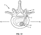
- Curved inflatable bone tamp 22 is removed from vertebra V and cannula C is inserted through pilot hole PH and into space S, as shown in FIG. 14 .
- Material M is inserted through cannula C and into space S, as also shown in FIG. 14 .
- Material M may be inserted into space S until material M fills all or a portion of space S.
- a kit containing one or more components of balloon catheter system 20 is provided.
- the kit may comprise components from any of the embodiments discussed herein.
- the kit comprises one or more of the inflation materials discussed herein.
- the kit comprises a plurality of cannulas, such as, for example, cannula C having different lengths configured for use with different size patients.
Landscapes
- Health & Medical Sciences (AREA)
- Life Sciences & Earth Sciences (AREA)
- Orthopedic Medicine & Surgery (AREA)
- Surgery (AREA)
- Biomedical Technology (AREA)
- Engineering & Computer Science (AREA)
- Nuclear Medicine, Radiotherapy & Molecular Imaging (AREA)
- Heart & Thoracic Surgery (AREA)
- Medical Informatics (AREA)
- Molecular Biology (AREA)
- Animal Behavior & Ethology (AREA)
- General Health & Medical Sciences (AREA)
- Public Health (AREA)
- Veterinary Medicine (AREA)
- Materials For Medical Uses (AREA)
Description
- The present disclosure generally relates to medical devices for the treatment of bone disorders, and more particularly to devices for treating spinal disorders, such as, for example, vertebral compression fractures.
- Height loss is commonly associated with spinal fractures, such as, for example, vertebral compression fractures. Spinal fractures affect a large segment of osteoporotic patients. It is estimated that approximately 700,000 spinal fractures occur annually from osteoporosis, for example. Procedures have been developed to treat spinal fractures. One such procedure is kyphoplasty. Kyphoplasty is a minimally invasive procedure that is used to treat spinal fractures, such as, for example, vertebral compression fractures by inserting one or more balloons, such as, for example, compliant balloons inside a fractured vertebral body. The balloon or balloons are inflated within the fractured vertebral body such that the cancellous bone of the vertebral body is pushed towards cortical walls of the vertebral body to form a cavity within the vertebral body. The cavity is then at least partially filled with a material, such as, for example, bone cement.
-
US 2013/345765 A1 discloses a surgical system and method for manipulating tissue. - However, conventional spinal fracture treatment procedures lack a balloon that can be inflated to have a curved configuration when the balloon has a maximum volume and pressure necessary for a kyphoplasty procedure. Conventional balloons typically have very thick walls and are made of a compliant material. The wall thins out when the balloon is inflated. Since inflation of the balloon is symmetric, the wall will thin out uniformly, and the outer arch of the balloon, which is longer than an inner arch of the balloon, will be thinner than the inner arch when the balloon is inflated. Indeed, once inflation starts, the outer arch will start thinning out further than the inner arch, which will create a path of least resistance outward on the outer arch of the balloon. This will create an off-axis skewed kidney shape inflation. Such variation of the wall thickness of the balloon when the balloon is inflated makes the balloon ineffective for balloon kyphoplasty procedures that require a curved balloon. This disclosure describes improvements over these prior art technologies.
- New devices are provided for the treatment of bone disorders, and more particularly devices for treating spinal disorders, such as, for example, vertebral compression fractures. The present invention discloses a curved inflatable bone tamp according to claim 1. Further embodiments of the present invention are disclosed in the dependent claims.
- Additional features and advantages of various embodiments will be set forth in part in the description that follows, and in part will be apparent from the description, or may be learned by practice of various embodiments. The advantages of various embodiments will be realized and attained by means of the elements and combinations particularly pointed out in the description and appended claims.
- The present disclosure will become more readily apparent from the specific description accompanied by the following drawings, in which:
-
FIG. 1 is a perspective view, in part phantom, of a surgical instrument in accordance with the principles of the present disclosure; -
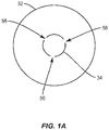
FIG. 1A is a cross sectional view of one embodiment of the surgical instrument shown inFIG. 1 ; -
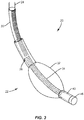
FIG. 2 is a perspective view of one embodiment of the surgical instrument shown inFIG. 1 ; -
FIG. 3 is a perspective view of one embodiment of the surgical instrument shown inFIG. 1 ; -
FIG. 4 is a side, cross sectional view of a component of the surgical instrument shown inFIG. 1 ; -
FIG. 5 is a side, cross sectional view of a component of the surgical instrument shown inFIG. 1 ; -
FIG. 6 is a plan view of a surgical instrument in accordance with the principles of the present disclosure being inserted into a vertebra; -
FIG. 7 is a plan view of the vertebra shown inFIG. 6 ; -
FIG. 8 is a plan view of the surgical instrument shown inFIG. 1 inserted into the vertebra shown inFIG. 6 ; -
FIG. 9 is a plan view of the surgical instrument shown inFIG. 1 inserted into the vertebra shown inFIG. 6 ; -
FIG. 10 is a plan view of the vertebra shown inFIG. 6 ; -
FIG. 11 is a plan view of a surgical instrument in accordance with the principles of the present disclosure being inserted into the vertebra shown inFIG. 6 ; -
FIG. 12 is a plan view of the surgical instrument shown inFIG. 1 inserted into the vertebra shown inFIG. 6 ; -
FIG. 13 is a plan view of the vertebra shown inFIG. 6 ; and -
FIG. 14 is a plan view of a surgical instrument in accordance with the principles of the present disclosure being inserted into the vertebra shown inFIG. 6 . - In some embodiments, the present disclosure relates to a system that includes a curved high pressure balloon catheter for unipedicular kyphoplasty. The system comprises a nested cannula and curved stylet to access a vertebral body through a unipedicular access. The curved stylet will create a pilot hole for positioning the curved balloon catheter through a midline of the vertebral body. The balloon catheter includes a curved super-elastic metallic inner tube, such as, for example, an inner tube made of Nitinol. The balloon catheter further includes a straight metallic outer shaft, a proximal design to connect to an inflation syringe and a distal high pressure balloon with a variable wall thickness when the balloon is uninflated or only partially inflated.
- In some embodiments, the high pressure balloon is formed with variable wall thickness when the balloon is uninflated or only partially inflated to improve the performance of inflation when it is inflated. The balloon will have a uniform thickness when inflated to improve balloon performance during a balloon kyphoplasty procedure. The variable wall when the balloon is uninflated or only partially inflated will improve the deflated profile and enhance the removal process. In some embodiments, the high pressure balloon is formed to be thicker on an outer curve or arch of the balloon and thinner on an inner curve or arch of the balloon. When the balloon is inflated, it will plastically deform to a more consistent wall thickness. The ratio of maximum to minimum wall thickness can be optimized for each size based on inflation volume and pressure. This improved design allows for a higher maximum inflation volume and better removal through an access cannula of the system. Providing a curved balloon that has a variable wall thickness when uninflated or only partially inflated and a uniform thickness when inflated will provide a controlled and uniform inflation shape. In some embodiments, the balloon has a lobed configuration when the balloon is uninflated and a long conical shape when the balloon is inflated.
- It is envisioned that the disclosed curved balloon catheter can be used for unipedicular kyphoplasty in patients with one or more vertebral compression fractures or as an adjunctive to local tumor control interventions. In some embodiments, the balloon is specifically targeted for a vertebral body and balloon kyphoplasty so that a shape of the balloon follows an anterior wall of the vertebral body. This will dictate a certain radius of curvature (i.e. about 25 mm) for the balloon to be positioned more anterior and passed the midline and to inflate to an optimum shape to cover the anterior 2/3 of the vertebral body for treatment of vertebral compression fractures.
- For the purposes of this specification and appended claims, unless otherwise indicated, all numbers expressing quantities of ingredients, percentages or proportions of materials, and other numerical values used in the specification and claims, are to be understood as being modified in all instances by the term "about." Accordingly, unless indicated to the contrary, the numerical parameters set forth in the following specification and attached claims are approximations that may vary depending upon the desired properties sought to be obtained by the present invention. At the very least, and not as an attempt to limit the application of the doctrine of equivalents to the scope of the claims, each numerical parameter should at least be construed in light of the number of reported significant digits and by applying ordinary rounding techniques.
- Notwithstanding the numerical ranges and parameters set forth herein, the broad scope of the invention are approximations, the numerical values set forth in the specific examples are reported as precisely as possible. Any numerical value, however, inherently contains certain errors necessarily resulting from the standard deviation found in their respective testing measurements. Moreover, all ranges disclosed herein are to be understood to encompass any and all subranges subsumed therein. For example, a range of "1 to 10" comprises any and all subranges between (and including) the minimum value of 1 and the maximum value of 10, that is, any and all subranges having a minimum value of equal to or greater than 1 and a maximum value of equal to or less than 10, e.g., 5.5 to 10.
- Reference will now be made in detail to certain embodiments of the invention, examples of which are illustrated in the accompanying drawings. While the invention will be described in conjunction with the illustrated embodiments, it will be understood that they are not intended to limit the invention to those embodiments. On the contrary, the invention is intended to cover all alternatives, modifications, and equivalents that may be comprised within the invention as defined by the appended claims.
- This disclosure is directed to an inflatable bone tamp, such as, for example, a
balloon catheter system 20. In some embodiments, the components ofballoon catheter system 20 can be fabricated from biologically acceptable materials suitable for medical applications, including metals, synthetic polymers, ceramics and bone material and/or their composites, depending on the particular application and/or preference of a medical practitioner. For example, the components of balloon catheter system 20, individually or collectively, can be fabricated from materials such as stainless steel alloys, commercially pure titanium, titanium alloys, Grade 5 titanium, super-elastic titanium alloys, cobalt-chrome alloys, stainless steel alloys, superelastic metallic alloys (e.g., Nitinol, super elasto-plastic metals, such as GUM METAL® manufactured by Toyota Material Incorporated of Japan), ceramics and composites thereof such as calcium phosphate (e.g., SKELITE™ manufactured by Biologix Inc.), thermoplastics such as polyaryletherketone (PAEK) including polyetheretherketone (PEEK), polyetherketoneketone (PEKK) and polyetherketone (PEK), carbon-PEEK composites, PEEK-BaSO4 polymeric rubbers, polyethylene terephthalate (PET), fabric, silicone, polyurethane, silicone-polyurethane copolymers, polymeric rubbers, polyolefin rubbers, hydrogels, semi-rigid and rigid materials, elastomers, rubbers, thermoplastic elastomers, thermoset elastomers, elastomeric composites, rigid polymers including polyphenylene, polyamide, polyimide, polyetherimide, polyethylene, epoxy, bone material including autograft, allograft, xenograft or transgenic cortical and/or corticocancellous bone, and tissue growth or differentiation factors, partially resorbable materials, such as, for example, composites of metals and calcium-based ceramics, composites of PEEK and calcium based ceramics, composites of PEEK with resorbable polymers, totally resorbable materials, such as, for example, calcium based ceramics such as calcium phosphate, tricalcium phosphate (TCP), hydroxyapatite (HA)-TCP, calcium sulfate, or other resorbable polymers such as polyaetide, polyglycolide, polytyrosine carbonate, polycaroplaetohe and their combinations. - Various components of
balloon catheter system 20 may have material composites, including the above materials, to achieve various desired characteristics such as strength, rigidity, elasticity, compliance, biomechanical performance, durability and radiolucency or imaging preference. The components ofballoon catheter system 20, individually or collectively, may also be fabricated from a heterogeneous material such as a combination of two or more of the above-described materials. The components ofballoon catheter system 20 may be monolithically formed, integrally connected or comprise fastening elements and/or instruments, as described herein. -
Balloon catheter system 20 includes a curved inflatable bone tamp 22 comprising an outer shaft, such as, for example ashaft 24 defining apassageway 26. In some embodiments,passageway 26 has a uniform diameter along an entire length ofshaft 24. In some embodiments,passageway 26 may have various cross section configurations, such as, for example, circular, oval, oblong, triangular, rectangular, square, polygonal, irregular, uniform, non-uniform, variable, tubular and/or tapered. In some embodiments,shaft 24 may at least initially have a straight configuration, and may be bent to have a curved configuration, as discussed herein. In some embodiments,shaft 24 may be pre-bent to have a curved configuration. In some embodiments,shaft 24 may include one or a plurality of surface features, such as, for example,ridges 28 to facilitate bending ofshaft 24 in a controlled manner.Adjacent ridges 28 define a channel therebetween. As shown inFIG. 1 ,ridges 28 are disposed alongshaft 24 in a linear, serial configuration such thatridges 28 extend parallel to one another to allowshaft 24 to bend aboutridges 28. In some embodiments,ridges 28 extend only along a portion of a length ofshaft 24. In some embodiments,ridges 28 extend only an entire length ofshaft 24. As shown inFIG. 1 ,ridges 28 each extend perpendicular to a length ofshaft 24. However, it is envisioned thatridges 28 may be disposed at alternate orientations, relative to the length ofshaft 24, such as, for example, transverse and/or other angular orientations such as acute or obtuse, co-axial and/or may be offset or staggered, depending upon, for example, the desired curvature ofshaft 24. - In some embodiments,
shaft 24 comprises a metallic material. In some embodiments,shaft 24 is laser cut, braided, or coiled. In some embodiments,shaft 24 is coated with a material, such as, for example, apolymer 30 configured to facilitate bonding of an inflatable member, such as, for example, aballoon 32 toshaft 24, as discussed herein. In some embodiments,polymer 30 can also encapsulate and seal the laser cut, braid, or coil to prevent material ingress or egress through a thickness ofshaft 24 that is coated withpolymer 30. In some embodiments,ridges 28 are formed by the metallic material. In some embodiments,ridges 28 are formed bypolymer 30. In some embodiments,ridges 28 are formed by the metallic material andpolymer 30. In some embodiments, only a distal portion ofshaft 24 is coated withpolymer 30. In some embodiments, only a portion ofshaft 24 that is bonded to balloon 32 is coated withpolymer 30. In some embodiments, only portions ofshaft 24 that are bonded to balloon 32 and includeridges 28 are coated withpolymer 30. In some embodiments,shaft 24 is coated withpolymer 30 along an entire length ofshaft 24. In some embodiments,shaft 24 is covered withpolymer 30 along at least a portion ofshaft 24. In some embodiments,polymer 30 includes a thermoplastic polymer, such as, for example, thermoplastic polyurethane (TPU). In some embodiments,polymer 30 includes a elastomeric polymer, such as, for example, a thermoplastic elastomer (TPE). - An inner shaft, such as, for example, a
shaft 34 is positioned withinpassageway 26.Shaft 34 extends between an end 36 anopposite end 38.End 36 is positioned withinpassageway 26 and end 38 is positioned outside ofpassageway 26.Shaft 34 is curved betweenend 36 andend 38. In some embodiments,shaft 34 is pre-bent to be curved betweenend 36 and end 38 such that whenshaft 34 is inserted throughpassageway 26,shaft 34 causesshaft 24 to move from a straight configuration to a curved configuration. In some embodiments,shaft 34 is pre-bent to have a uniform radius of curvature. In some embodiments,shaft 34 is pre-bent to have a radius of curvature that varies along a length ofshaft 34. In some embodiments,shaft 34 comprises a shape memory alloy, such as, for example, a super-elastic shape memory alloy. In some embodiments,shaft 34 comprises Nitinol. In some embodiments,shaft 34 is laser cut, braided, or coiled. In some embodiments,shaft 34 is coated with a material, such as, for example, apolymer 40 configured to facilitate bonding ofballoon 32 toshaft 34, as discussed herein. In some embodiments,polymer 40 can also encapsulate and seal the laser cut, braid, or coil ofshaft 34 to prevent material ingress or egress through a thickness ofshaft 34 that is coated withpolymer 40. In some embodiments,shaft 34 includes a rigid material, such as, for example, stainless steel (SST) or nickel titanium (NiTi), wherein at least a portion ofshaft 34 includes one or more laser cuts to provideshaft 34 with the pre-bent shape. In some embodiments, the laser cuts are uniaxial. In some embodiments, the laser cuts are multiaxial. In some embodiments, the portion ofshaft 34 that includes the laser cuts is jacketed or covered withpolymer 40. In some embodiments,polymer 40 includes a thermoplastic polymer, such as, for example, thermoplastic polyurethane (TPU). In some embodiments,polymer 40 includes an elastomeric polymer, such as, for example, a thermoplastic elastomer (TPE). -
Shaft 34 defines alumen 42 configured to move an inflation material, such as, for example, air, saline, or a contrast solution into and out ofballoon 32 to moveballoon 32 between an uninflated configuration and an inflated configuration, as discussed herein. In some embodiments,lumen 42 has a uniform diameter along an entire length ofshaft 34. In some embodiments,lumen 42 may have various cross section configurations, such as, for example, circular, oval, oblong, triangular, rectangular, square, polygonal, irregular, uniform, non-uniform, variable, tubular and/or tapered. In some embodiments, a distal end oflumen 42 is closed to prevent the inflation material from moving out oflumen 42 through a distal end of lumen. In some embodiments, the distal end oflumen 42 includes anopening 44 to allow an instrument, such as, for example a guide wire to be inserted throughlumen 42 such that the guide wire can extend throughopening 44 and into tissue in order so that bone tamp 22 can be guided along the guide wire to a target location. In some embodiments, bone tamp 22 may include aremovable cap 46, as shown inFIG. 2 , for example.Cap 46 can be inserted ontoshaft 34 such thatcap 46 covers opening 44. In some embodiments, cap 46 can be variously connected withshaft 34, such as, for example, monolithic, integral connection, frictional engagement, threaded engagement, mutual grooves, screws, adhesive, nails, barbs and/or raised element. In some embodiments,polymer 40 includes a plurality of spaced apartgrooves 45 that each extend parallel to a length ofshaft 34, as shown inFIG. 1 .Grooves 45 may be used to enhance fixation ofcap 46 withshaft 34 and/or bonding ofballoon 32 toshaft 34. In some embodiments,grooves 45 may be disposed at alternate orientations, relative to the length ofshaft 34, such as, for example, transverse, perpendicular and/or other angular orientations such as acute or obtuse, co-axial and/or may be offset or staggered. - In some embodiments,
balloon 32 is made from a resilient biocompatible material. In one embodiment,balloon 32 is a compliant balloon that resists stretching. In one embodiment,balloon 32 comprises polyolefin copolymer (POC), Polyurethane, Nylon. In one embodiment,balloon 32 is a non-compliant or semi-compliant balloon that stretches, at least to some degree. In one embodiment,balloon 32 comprises polyethylene terapthelate (PET). In some embodiments,balloon 32 can have various cross section configurations whenballoon 32 is in the inflated configuration, such as, for example, oval, oblong, triangular, rectangular, square, polygonal, irregular, uniform, non-uniform, variable, tubular and/or tapered. In some embodiments, an outer surface ofballoon 32 may have various surface configurations, such as, for example, smooth and/or surface configurations to enhance fixation with tissue, such as, for example, rough, arcuate, undulating, porous, semi-porous, dimpled, polished and/or textured. -
Balloon 32 has aleg 48 that is bonded topolymer 30 to coupleleg 48 toshaft 24. In some embodiments,leg 48 is bonded topolymer 30 using heat or an adhesive, for example.Bonding leg 48 topolymer 30 will provide a better bond than would bondingleg 48 to a portion ofshaft 24 that does not includepolymer 30 using heat or an adhesive. Balloon has aleg 50 that is bonded topolymer 40 to coupleleg 50 toshaft 34. In some embodiments,leg 50 is bonded topolymer 40 using heat or an adhesive, for example.Bonding leg 50 topolymer 40 will provide a better bond than would bondingleg 50 to a portion ofshaft 34 that does not includepolymer 40 using heat or an adhesive.Balloon 32 has abody 52 that extends fromleg 48 toleg 50. That is,body 52 is positioned betweenleg 48 andleg 50.Body 52 includes an inner surface that defines achamber 54.Balloon 32 extends along a curved axis A, as shown inFIGS. 4 and 5 , to provideballoon 32 with a curved configuration. In some embodiments, axis A has a continuous and/or constant radius of curvature. In some embodiments, axis A has a radius of curvature that is equal to the radius of curvature ofshaft 32. - In some embodiments,
shaft 34 has a non-porous, solid wall configuration (e.g.,FIGS. 1 and1A ) and includes one or a plurality ofinflation ports 56 that each extend through a thickness ofshaft 34 and are in communication withlumen 42. As the inflation material moves throughlumen 42, the inflation material will exitlumen 42 throughinflation ports 56 and enterchamber 54 to moveballoon 32 from an uninflated configuration (e.g.,FIG. 1 ) to an inflated configuration (e.g.,FIG. 3 ). In some embodiments,inflation ports 56 are spaced apart from each other along a length ofshaft 34 and/or are spaced apart radially about a circumference ofshaft 34, as shown inFIG. 1A . - In embodiments wherein
shaft 34 is laser cut, braided, or coiled, the inflation material can enterchamber 54 through gaps or pores inshaft 34 that are not covered or encapsulated bypolymer 40. For example, the gaps or pores may be defined by spaces between coils, as can be seen fromFIG. 2 . Likewise, the gaps or pores may be defined by spaces between interlaced strands that make up the braid, as can be seen fromFIG. 3 . As the inflation material moves throughlumen 42, the inflation material will exitlumen 42 through the gaps or pores inshaft 34 and enterchamber 54 to moveballoon 32 from the uninflated configuration to the inflated configuration. -
Leg 48 has a thickness t1 defined by the distance between opposite inner and outer surfaces ofleg 48 andleg 50 has a thickness t2 defined by the distance between opposite inner and outer surfaces ofleg 50, as shown inFIG. 4 . In some embodiments, thickness t1 is equal to thickness t2. In some embodiments, thickness t1 is less than thickness t2. In some embodiments, thickness t1 is greater than thickness t2. In some embodiments,leg 48 has a length that is equal to a length ofleg 50. In some embodiments, the length ofleg 48 is greater than the length ofleg 50. In some embodiments, the length ofleg 48 is less than the length ofleg 50. -
Body 52 ofballoon 32 includes an inner curve, such as, for example, a concaveinner portion 58 that extends fromleg 48 toleg 50 and an opposite outer curve, such as, for example, a convexouter portion 60 that extends fromleg 48 toleg 50. As shown inFIGS. 4 and 5 ,portion 58 has a length l1 fromleg 48 toleg 50 andportion 60 has a length l2 fromleg 48 toleg 50, length l2 being greater than length l1.Portion 58 has a thickness t3 defined by the distance between opposite inner and outer surfaces ofportion 58 andportion 60 has a thickness t4 defined by the distance between opposite inner and outer surfaces ofportion 60, as also shown inFIG. 5 . - When
balloon 32 is in the uninflated configuration, thickness t3 is less than thickness t4, as shown inFIG. 4 . Whenballoon 32 is in the inflated configuration, thickness t3 is equal to or substantially equal to thickness t4, as shown inFIG. 5 . That is, because length l2 is greater than length l1, asballoon 32 moves from the uninflated configuration to the inflated configuration,portion 60 thins out more thanportion 58 thins out so that the thicknesses ofportions balloon 32 is in the inflated configuration. The configuration ofballoon 32 described above also allowsballoon 32 to expand uniformly aboutshaft 34. In some embodiments, thickness t4 is at least 10% greater than thickness t3 whenballoon 32 is in the uninflated configuration. In some embodiments, thickness t4 is at least 25% greater than thickness t3 whenballoon 32 is in the uninflated configuration. In some embodiments, thickness t4 is 10%, 11%, 12%, 13%, 14%, 15%, 16%, 17%, 18%, 19%, 20%, 21%, 22%, 23%, 24%, 25%, 26%, 27%, 28%, 29%, or 30% greater than thickness t3 whenballoon 32 is in the uninflated configuration. In some embodiments, thickness t3 is between about 0,1016 mm (0,004 inches) and about 0,2032 mm (0,008 inches) whenballoon 32 is in the uninflated configuration and thickness t4 is between about 0,1524 mm (0,006 inches) and about 0,254 mm (0,01 inches) whenballoon 32 is in the uninflated configuration. In some embodiments, thickness t3 is 0,1524 mm (0,006 inches) whenballoon 32 is in the uninflated configuration and thickness t4 is 0,2032 mm (0,008 inches) whenballoon 32 is in the uninflated configuration. - As shown in
FIGS. 4 and 5 ,balloon 32 maintains a curved configuration asballoon 32 moves from the uninflated configuration to the inflated configuration. In some embodiments,balloon 32 inflates uniformly aboutshaft 32 such that the radius of curvature of axis A remains constant asballoon 32 moves from the uninflated configuration to the inflated configuration. The ability of thickness t3 to be less than thickness t4 whenballoon 32 is in the uninflated configuration and thickness t3 to be equal or substantially equal to thickness t4 whenballoon 32 is in the inflated configuration will improve the performance ofballoon 32 and increase the maximum inflation volume of balloon at higher pressure. As shown inFIGS. 4 and 5 , lengths l1, l2 each remain constant asballoon 32 moves from the uninflated configuration to the inflated configuration. - In use, to treat a bone disorder, such as, for example, a spinal fracture, a medical practitioner obtains access to a target location including at least one vertebra, such as, for example, a fractured vertebra V, in any appropriate manner, such as through incision and retraction of tissue. It is envisioned that the
balloon catheter system 20 may be used in any existing surgical method or technique including open surgery, mini-open surgery, minimally invasive surgery including percutaneous surgical implantation, whereby vertebra V is accessed through a micro-incision, or sleeve that provides a protected passageway to the area. Once access to the surgical site(s) are obtained, the particular surgical procedure is performed for treating the bone disorder. - As shown in
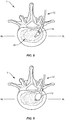
FIG. 6 ,balloon catheter system 20 includes acurved stylet 62 that is inserted through vertebra V and into a vertebral body VB of vertebra V to access vertebral body VB through a unipedicular approach and create a curved pilot hole PH, as shown inFIG. 7 . Curved inflatable bone tamp 22 is inserted through pilot hole PH withballoon 32 in the uninflated configurationsuch balloon 32 is positioned within vertebral body VB, as shown inFIG. 8 .Balloon 32 is moved from the uninflated configuration to the inflated configuration as discussed herein and shown inFIG. 9 . Asballoon 32 moves from the uninflated configuration to the inflated configuration,balloon 32 creates a void, such as, for example, a space S within vertebral body VB, as shown inFIG. 10 . Curved inflatable bone tamp 22 is removed from vertebra V and a cannula C ofsystem 20 is inserted through pilot hole PH and into space S, as shown inFIG. 11 . In some embodiments,balloon 32 is moved from the inflated configuration to the uninflated configuration prior to removing curved inflatable bone tamp 22 from vertebra V. In some embodiments, negative pressure, such as, for example, a vacuum is applied to lumen 42 to draw the inflation material out of lumen and moveballoon 32 from the inflated configuration to the uninflated configuration. A material, such as, for example, a bone filler material M is inserted through cannula C and into space S, as also shown inFIG. 11 . Material M may be inserted into space S until material M fills all or a portion of space S. Cannula C is removed from vertebra V and material M is allowed to cure to treat the fracture by reducing pain from the fracture, stabilizing vertebra V and/or restoring vertebra V back to its normal height. - In some embodiments, pilot hole PH is oriented to position
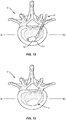
balloon 32 such thatballoon 32 follows an anterior wall AW of vertebral body VB whenballoon 32 is inflated within vertebral body VB, as shown inFIG. 12 . As shown inFIG. 12 ,balloon 32 is positioned more anterior than posterior and extends passed midline M of vertebral body VB. In some embodiments, the size and shape ofballoon 32 can be customized such thatballoon 32 covers at least the anterior 2/3 of vertebral body VB to properly treat a vertebral compression fracture ofvertebra V. Balloon 32 is moved from the uninflated configuration to the inflated configuration to create space S within vertebral body VB, as shown inFIG. 13 . Curved inflatable bone tamp 22 is removed from vertebra V and cannula C is inserted through pilot hole PH and into space S, as shown inFIG. 14 . Material M is inserted through cannula C and into space S, as also shown inFIG. 14 . Material M may be inserted into space S until material M fills all or a portion of space S. - In some embodiments, a kit containing one or more components of
balloon catheter system 20 is provided. The kit may comprise components from any of the embodiments discussed herein. In some embodiments, the kit comprises one or more of the inflation materials discussed herein. In some embodiments, the kit comprises a plurality of cannulas, such as, for example, cannula C having different lengths configured for use with different size patients.
Claims (11)
- A curved inflatable bone tamp (22) comprising:an outer shaft (24) defining a passageway (26);an inner shaft (34) positioned within the passageway (26), the inner shaft (34) extending between opposite first and second ends (36, 38), the inner shaft (34) defining a lumen (42), the inner shaft (34) being curved between the first end (36) and the second end (38); anda balloon (32) having a curved configuration comprising a concave inner portion (58) and a convex outer portion (60), the balloon (32) having a first leg (48) coupled to the outer shaft (24) and a second leg (50) coupled to the inner shaft (34) such that a material (M) can flow through the lumen (42) and into the balloon (32) to inflate the balloon (32), the balloon (32) comprising a wall having the concave inner portion (58) and the convex outer portion (60), the wall having a variable thickness between the legs (48, 50) when the balloon (32) is uninflated,characterized in that
the concave inner portion (58) between the legs (48, 50) has a first thickness (t3) when the balloon (32) is uninflated, the convex outer portion between the legs (48, 50) has a second thickness (t4) when the balloon (32) is uninflated, the second thickness (t4) is greater than the first thickness (t3); and
the wall has a uniform thickness between the legs (48, 50) when the balloon (32) is inflated. - A curved inflatable bone tamp (22) as recited in claim 1, wherein the balloon (32) has a lobed configuration when the balloon (32) is uninflated and a long conical shape when the balloon (32) is inflated.
- A curved inflatable bone tamp (22) as recited in claim 1 or 2, wherein portions of the shafts (24, 34) are coated with a polymer (30, 40), the legs (48, 50) being bonded to the polymer (30, 40).
- A curved inflatable bone tamp (22) as recited in one of claims 1-3, wherein the second thickness (t4) is at least 10% greater than the first thickness (t3).
- A curved inflatable bone tamp (22) as recited in one of claims claim 1-3, wherein the second thickness (t4) is at least 25% greater than the first thickness (t3).
- A curved inflatable bone tamp (22) as recited in one of claims 1-5, wherein the convex outer portion (60) has a projection length (12) that is greater than a projection length (11) of the concave inner portion (58).
- A curved inflatable bone tamp (22) as recited in one of claims 1-6, wherein the balloon (32) is configured to inflate uniformly around the inner shaft (34).
- A curved inflatable bone tamp (22) as recited in one of claims 1-7, wherein the outer shaft (24) comprises a metallic material that is coated with a polymer (30), the first leg (48) being bonded to the polymer (30).
- A curved inflatable bone tamp (22) as recited in one of claims 1-8, wherein the inner shaft (34) comprises a superelastic material that is coated with a polymer (40), the second leg (50) being bonded to the polymer (40).
- A curved inflatable bone tamp (22) as recited in one of claims 1-9, wherein the inner shaft (34) comprises a superelastic shape memory alloy that is coated with a polymer (40), the second leg (50) being bonded to the polymer (40).
- A curved inflatable bone tamp (22) as recited in one of claims 1-10, wherein the first leg (48) of the balloon (32) comprises a linear channel, portions of the shafts (24, 34) being positioned within the channel, the portions each being continuously curved.
Applications Claiming Priority (1)
| Application Number | Priority Date | Filing Date | Title |
|---|---|---|---|
| US15/784,254 US10779870B2 (en) | 2017-10-16 | 2017-10-16 | Curved inflatable bone tamp with variable wall thickness |
Publications (2)
| Publication Number | Publication Date |
|---|---|
| EP3473199A1 EP3473199A1 (en) | 2019-04-24 |
| EP3473199B1 true EP3473199B1 (en) | 2021-04-28 |
Family
ID=63678453
Family Applications (1)
| Application Number | Title | Priority Date | Filing Date |
|---|---|---|---|
| EP18195882.8A Active EP3473199B1 (en) | 2017-10-16 | 2018-09-21 | Curved inflatable bone tamp with variable wall thickness |
Country Status (2)
| Country | Link |
|---|---|
| US (2) | US10779870B2 (en) |
| EP (1) | EP3473199B1 (en) |
Families Citing this family (4)
| Publication number | Priority date | Publication date | Assignee | Title |
|---|---|---|---|---|
| US10231770B2 (en) | 2015-01-09 | 2019-03-19 | Medtronic Holding Company Sárl | Tumor ablation system |
| US11229466B2 (en) | 2018-01-12 | 2022-01-25 | KyphEZE, Inc. | Bone expansion systems and methods |
| US11484355B2 (en) * | 2020-03-02 | 2022-11-01 | Medtronic Holding Company Sàrl | Inflatable bone tamp and method for use of inflatable bone tamp |
| US12208221B2 (en) | 2020-04-08 | 2025-01-28 | Covidien Lp | Balloon guiding sheath having a textured surface |
Family Cites Families (38)
| Publication number | Priority date | Publication date | Assignee | Title |
|---|---|---|---|---|
| JP2555298B2 (en) | 1990-11-10 | 1996-11-20 | テルモ株式会社 | CATHETER BALLOON, CATHETER BALLOON MANUFACTURING METHOD, AND BALLOON CATHETER |
| US5320605A (en) | 1993-01-22 | 1994-06-14 | Harvinder Sahota | Multi-wire multi-balloon catheter |
| US6716216B1 (en) * | 1998-08-14 | 2004-04-06 | Kyphon Inc. | Systems and methods for treating vertebral bodies |
| US6554795B2 (en) | 1997-03-06 | 2003-04-29 | Medtronic Ave, Inc. | Balloon catheter and method of manufacture |
| US5961536A (en) | 1997-10-14 | 1999-10-05 | Scimed Life Systems, Inc. | Catheter having a variable length balloon and method of using the same |
| US6228072B1 (en) * | 1998-02-19 | 2001-05-08 | Percusurge, Inc. | Shaft for medical catheters |
| CA2379670A1 (en) | 1999-08-12 | 2001-02-22 | Wilson-Cook Medical Inc. | Dilation balloon having multiple diameters |
| US6544224B1 (en) | 2000-05-05 | 2003-04-08 | Advanced Cardiovascular Systems, Inc. | Lobed balloon catheter and method of use |
| US6607545B2 (en) | 2000-12-27 | 2003-08-19 | Ethicon, Inc. | Conformal surgical balloon with varying wall expansibility |
| US6951569B2 (en) | 2000-12-27 | 2005-10-04 | Ethicon, Inc. | Surgical balloon having varying wall thickness |
| US7544196B2 (en) * | 2001-02-20 | 2009-06-09 | Orthovita, Inc. | System and kit for delivery of restorative materials |
| US7048729B2 (en) * | 2002-04-04 | 2006-05-23 | Meglin Allen J | Catheter and method of fluid removal from a body cavity |
| US9782572B2 (en) * | 2002-09-30 | 2017-10-10 | Nordson Corporation | Apparatus and methods for treating bone structures, tissues and ducts using a narrow gauge cannula system |
| WO2012134592A1 (en) * | 2011-03-25 | 2012-10-04 | Advanced Polymers, Inc. | Apparatus and methods for accessing and dilating bone structures using a narrow gauge cannula |
| US7175607B2 (en) | 2003-03-06 | 2007-02-13 | Advanced Cardiovascular Systems, Inc. | Catheter balloon liner with variable thickness and method for making same |
| US7494612B2 (en) * | 2004-10-29 | 2009-02-24 | Boston Scientific Scimed, Inc. | Medical balloon folding method and tooling |
| US20070010845A1 (en) | 2005-07-08 | 2007-01-11 | Gorman Gong | Directionally controlled expandable device and methods for use |
| US20070066987A1 (en) * | 2005-09-09 | 2007-03-22 | Scanlan Donald L Jr | Bone navigation probes |
| WO2007053823A2 (en) | 2005-10-31 | 2007-05-10 | Biolucent, Inc. | Brachytherapy apparatus and methods of using same |
| US20090131867A1 (en) * | 2007-11-16 | 2009-05-21 | Liu Y King | Steerable vertebroplasty system with cavity creation element |
| US9510885B2 (en) * | 2007-11-16 | 2016-12-06 | Osseon Llc | Steerable and curvable cavity creation system |
| US20090143634A1 (en) | 2007-12-04 | 2009-06-04 | Cytyc Corporation | Brachytherapy Balloon Features |
| WO2009155319A1 (en) | 2008-06-17 | 2009-12-23 | Soteira, Inc. | Devices and methods for fracture reduction |
| US20100298832A1 (en) * | 2009-05-20 | 2010-11-25 | Osseon Therapeutics, Inc. | Steerable curvable vertebroplasty drill |
| US8221349B2 (en) | 2009-10-29 | 2012-07-17 | Kyphon Sarl | Anterior inflation balloon |
| US8262609B2 (en) | 2009-10-29 | 2012-09-11 | Kyphon Sarl | Anterior inflation balloon |
| US20110264099A1 (en) * | 2010-04-23 | 2011-10-27 | Kyphon SÀRL | Multi-directional cement delivery system |
| TWI579007B (en) * | 2010-07-02 | 2017-04-21 | 艾格諾福斯保健公司 | Use of bone regenerative material |
| US20120197319A1 (en) * | 2011-01-27 | 2012-08-02 | Kyphon Sarl | Inflatable bone tamp with adjustable working length |
| EP2793722A1 (en) * | 2011-12-22 | 2014-10-29 | DePuy Synthes Products, LLC | Length-adjustable vertebral body balloon |
| US8740842B2 (en) | 2012-02-07 | 2014-06-03 | Boston Scientific Scimed, Inc. | Kerstpiek tip for medical devices |
| CA3201083A1 (en) | 2012-06-20 | 2013-12-27 | Stryker Corporation | Systems and methods for off-axis tissue manipulation |
| US9295510B2 (en) | 2013-02-06 | 2016-03-29 | Kyphon SÀRL | Device for performing a surgical procedure and methods of use |
| US9717551B2 (en) * | 2013-02-21 | 2017-08-01 | Carefusion 2200, Inc. | Intravertebral tissue ablation device and method |
| US9204915B2 (en) | 2013-03-14 | 2015-12-08 | Kyphon Sarl | Device for performing a surgical procedure and method |
| JP6311031B2 (en) | 2013-11-11 | 2018-04-11 | ヨン チュル アン、 | Balloon catheter |
| US9730707B2 (en) * | 2014-08-20 | 2017-08-15 | Kyphon SÀRL | Surgical instrument with graduated markings correlating to angulation |
| HK1243015A1 (en) | 2014-11-17 | 2018-07-06 | TriReme Medical, LLC | Balloon catheter system |
-
2017
- 2017-10-16 US US15/784,254 patent/US10779870B2/en active Active
-
2018
- 2018-09-21 EP EP18195882.8A patent/EP3473199B1/en active Active
-
2020
- 2020-08-04 US US16/984,388 patent/US11413080B2/en active Active
Non-Patent Citations (1)
| Title |
|---|
| None * |
Also Published As
| Publication number | Publication date |
|---|---|
| US20200360069A1 (en) | 2020-11-19 |
| US20190110826A1 (en) | 2019-04-18 |
| US10779870B2 (en) | 2020-09-22 |
| EP3473199A1 (en) | 2019-04-24 |
| US11413080B2 (en) | 2022-08-16 |
Similar Documents
| Publication | Publication Date | Title |
|---|---|---|
| US11413080B2 (en) | Curved inflatable bone tamp with variable wall thickness | |
| US10864020B2 (en) | Bone fastener for a spinal surgical system | |
| US12408962B2 (en) | Bone anchor | |
| EP3260069B1 (en) | Inflatable bone tamp with flow control | |
| US11432862B2 (en) | High pressure balloon catheter with pressure regulating valve | |
| EP3505112B1 (en) | Scoop cannula with deflectable wings | |
| US11013544B2 (en) | Surgical system and methods of use | |
| US9204915B2 (en) | Device for performing a surgical procedure and method | |
| EP3520725B1 (en) | Vertebral body access cannula with enhanced bending stiffness | |
| US10993755B2 (en) | Inflatable bone tamp with flow control and methods of use | |
| US10070902B2 (en) | Spinal implant system and method |
Legal Events
| Date | Code | Title | Description |
|---|---|---|---|
| PUAI | Public reference made under article 153(3) epc to a published international application that has entered the european phase |
Free format text: ORIGINAL CODE: 0009012 |
|
| STAA | Information on the status of an ep patent application or granted ep patent |
Free format text: STATUS: THE APPLICATION HAS BEEN PUBLISHED |
|
| AK | Designated contracting states |
Kind code of ref document: A1 Designated state(s): AL AT BE BG CH CY CZ DE DK EE ES FI FR GB GR HR HU IE IS IT LI LT LU LV MC MK MT NL NO PL PT RO RS SE SI SK SM TR |
|
| AX | Request for extension of the european patent |
Extension state: BA ME |
|
| STAA | Information on the status of an ep patent application or granted ep patent |
Free format text: STATUS: REQUEST FOR EXAMINATION WAS MADE |
|
| 17P | Request for examination filed |
Effective date: 20191017 |
|
| RBV | Designated contracting states (corrected) |
Designated state(s): AL AT BE BG CH CY CZ DE DK EE ES FI FR GB GR HR HU IE IS IT LI LT LU LV MC MK MT NL NO PL PT RO RS SE SI SK SM TR |
|
| GRAP | Despatch of communication of intention to grant a patent |
Free format text: ORIGINAL CODE: EPIDOSNIGR1 |
|
| STAA | Information on the status of an ep patent application or granted ep patent |
Free format text: STATUS: GRANT OF PATENT IS INTENDED |
|
| RIC1 | Information provided on ipc code assigned before grant |
Ipc: A61B 17/88 20060101AFI20201111BHEP Ipc: A61M 25/10 20130101ALI20201111BHEP Ipc: A61B 17/00 20060101ALI20201111BHEP |
|
| INTG | Intention to grant announced |
Effective date: 20201214 |
|
| GRAS | Grant fee paid |
Free format text: ORIGINAL CODE: EPIDOSNIGR3 |
|
| GRAA | (expected) grant |
Free format text: ORIGINAL CODE: 0009210 |
|
| STAA | Information on the status of an ep patent application or granted ep patent |
Free format text: STATUS: THE PATENT HAS BEEN GRANTED |
|
| AK | Designated contracting states |
Kind code of ref document: B1 Designated state(s): AL AT BE BG CH CY CZ DE DK EE ES FI FR GB GR HR HU IE IS IT LI LT LU LV MC MK MT NL NO PL PT RO RS SE SI SK SM TR |
|
| REG | Reference to a national code |
Ref country code: GB Ref legal event code: FG4D |
|
| REG | Reference to a national code |
Ref country code: CH Ref legal event code: EP |
|
| REG | Reference to a national code |
Ref country code: AT Ref legal event code: REF Ref document number: 1386229 Country of ref document: AT Kind code of ref document: T Effective date: 20210515 |
|
| REG | Reference to a national code |
Ref country code: DE Ref legal event code: R096 Ref document number: 602018016116 Country of ref document: DE |
|
| REG | Reference to a national code |
Ref country code: IE Ref legal event code: FG4D |
|
| REG | Reference to a national code |
Ref country code: LT Ref legal event code: MG9D |
|
| REG | Reference to a national code |
Ref country code: AT Ref legal event code: MK05 Ref document number: 1386229 Country of ref document: AT Kind code of ref document: T Effective date: 20210428 |
|
| PG25 | Lapsed in a contracting state [announced via postgrant information from national office to epo] |
Ref country code: FI Free format text: LAPSE BECAUSE OF FAILURE TO SUBMIT A TRANSLATION OF THE DESCRIPTION OR TO PAY THE FEE WITHIN THE PRESCRIBED TIME-LIMIT Effective date: 20210428 Ref country code: LT Free format text: LAPSE BECAUSE OF FAILURE TO SUBMIT A TRANSLATION OF THE DESCRIPTION OR TO PAY THE FEE WITHIN THE PRESCRIBED TIME-LIMIT Effective date: 20210428 Ref country code: HR Free format text: LAPSE BECAUSE OF FAILURE TO SUBMIT A TRANSLATION OF THE DESCRIPTION OR TO PAY THE FEE WITHIN THE PRESCRIBED TIME-LIMIT Effective date: 20210428 Ref country code: NL Free format text: LAPSE BECAUSE OF FAILURE TO SUBMIT A TRANSLATION OF THE DESCRIPTION OR TO PAY THE FEE WITHIN THE PRESCRIBED TIME-LIMIT Effective date: 20210428 Ref country code: BG Free format text: LAPSE BECAUSE OF FAILURE TO SUBMIT A TRANSLATION OF THE DESCRIPTION OR TO PAY THE FEE WITHIN THE PRESCRIBED TIME-LIMIT Effective date: 20210728 Ref country code: AT Free format text: LAPSE BECAUSE OF FAILURE TO SUBMIT A TRANSLATION OF THE DESCRIPTION OR TO PAY THE FEE WITHIN THE PRESCRIBED TIME-LIMIT Effective date: 20210428 |
|
| PG25 | Lapsed in a contracting state [announced via postgrant information from national office to epo] |
Ref country code: NO Free format text: LAPSE BECAUSE OF FAILURE TO SUBMIT A TRANSLATION OF THE DESCRIPTION OR TO PAY THE FEE WITHIN THE PRESCRIBED TIME-LIMIT Effective date: 20210728 Ref country code: LV Free format text: LAPSE BECAUSE OF FAILURE TO SUBMIT A TRANSLATION OF THE DESCRIPTION OR TO PAY THE FEE WITHIN THE PRESCRIBED TIME-LIMIT Effective date: 20210428 Ref country code: PL Free format text: LAPSE BECAUSE OF FAILURE TO SUBMIT A TRANSLATION OF THE DESCRIPTION OR TO PAY THE FEE WITHIN THE PRESCRIBED TIME-LIMIT Effective date: 20210428 Ref country code: PT Free format text: LAPSE BECAUSE OF FAILURE TO SUBMIT A TRANSLATION OF THE DESCRIPTION OR TO PAY THE FEE WITHIN THE PRESCRIBED TIME-LIMIT Effective date: 20210830 Ref country code: SE Free format text: LAPSE BECAUSE OF FAILURE TO SUBMIT A TRANSLATION OF THE DESCRIPTION OR TO PAY THE FEE WITHIN THE PRESCRIBED TIME-LIMIT Effective date: 20210428 Ref country code: RS Free format text: LAPSE BECAUSE OF FAILURE TO SUBMIT A TRANSLATION OF THE DESCRIPTION OR TO PAY THE FEE WITHIN THE PRESCRIBED TIME-LIMIT Effective date: 20210428 Ref country code: GR Free format text: LAPSE BECAUSE OF FAILURE TO SUBMIT A TRANSLATION OF THE DESCRIPTION OR TO PAY THE FEE WITHIN THE PRESCRIBED TIME-LIMIT Effective date: 20210729 Ref country code: IS Free format text: LAPSE BECAUSE OF FAILURE TO SUBMIT A TRANSLATION OF THE DESCRIPTION OR TO PAY THE FEE WITHIN THE PRESCRIBED TIME-LIMIT Effective date: 20210828 |
|
| REG | Reference to a national code |
Ref country code: NL Ref legal event code: MP Effective date: 20210428 |
|
| PG25 | Lapsed in a contracting state [announced via postgrant information from national office to epo] |
Ref country code: RO Free format text: LAPSE BECAUSE OF FAILURE TO SUBMIT A TRANSLATION OF THE DESCRIPTION OR TO PAY THE FEE WITHIN THE PRESCRIBED TIME-LIMIT Effective date: 20210428 Ref country code: DK Free format text: LAPSE BECAUSE OF FAILURE TO SUBMIT A TRANSLATION OF THE DESCRIPTION OR TO PAY THE FEE WITHIN THE PRESCRIBED TIME-LIMIT Effective date: 20210428 Ref country code: CZ Free format text: LAPSE BECAUSE OF FAILURE TO SUBMIT A TRANSLATION OF THE DESCRIPTION OR TO PAY THE FEE WITHIN THE PRESCRIBED TIME-LIMIT Effective date: 20210428 Ref country code: EE Free format text: LAPSE BECAUSE OF FAILURE TO SUBMIT A TRANSLATION OF THE DESCRIPTION OR TO PAY THE FEE WITHIN THE PRESCRIBED TIME-LIMIT Effective date: 20210428 Ref country code: ES Free format text: LAPSE BECAUSE OF FAILURE TO SUBMIT A TRANSLATION OF THE DESCRIPTION OR TO PAY THE FEE WITHIN THE PRESCRIBED TIME-LIMIT Effective date: 20210428 Ref country code: SK Free format text: LAPSE BECAUSE OF FAILURE TO SUBMIT A TRANSLATION OF THE DESCRIPTION OR TO PAY THE FEE WITHIN THE PRESCRIBED TIME-LIMIT Effective date: 20210428 Ref country code: SM Free format text: LAPSE BECAUSE OF FAILURE TO SUBMIT A TRANSLATION OF THE DESCRIPTION OR TO PAY THE FEE WITHIN THE PRESCRIBED TIME-LIMIT Effective date: 20210428 |
|
| REG | Reference to a national code |
Ref country code: DE Ref legal event code: R097 Ref document number: 602018016116 Country of ref document: DE |
|
| PLBE | No opposition filed within time limit |
Free format text: ORIGINAL CODE: 0009261 |
|
| STAA | Information on the status of an ep patent application or granted ep patent |
Free format text: STATUS: NO OPPOSITION FILED WITHIN TIME LIMIT |
|
| 26N | No opposition filed |
Effective date: 20220131 |
|
| REG | Reference to a national code |
Ref country code: CH Ref legal event code: PL |
|
| REG | Reference to a national code |
Ref country code: BE Ref legal event code: MM Effective date: 20210930 |
|
| PG25 | Lapsed in a contracting state [announced via postgrant information from national office to epo] |
Ref country code: IS Free format text: LAPSE BECAUSE OF FAILURE TO SUBMIT A TRANSLATION OF THE DESCRIPTION OR TO PAY THE FEE WITHIN THE PRESCRIBED TIME-LIMIT Effective date: 20210828 Ref country code: MC Free format text: LAPSE BECAUSE OF FAILURE TO SUBMIT A TRANSLATION OF THE DESCRIPTION OR TO PAY THE FEE WITHIN THE PRESCRIBED TIME-LIMIT Effective date: 20210428 Ref country code: AL Free format text: LAPSE BECAUSE OF FAILURE TO SUBMIT A TRANSLATION OF THE DESCRIPTION OR TO PAY THE FEE WITHIN THE PRESCRIBED TIME-LIMIT Effective date: 20210428 |
|
| PG25 | Lapsed in a contracting state [announced via postgrant information from national office to epo] |
Ref country code: LU Free format text: LAPSE BECAUSE OF NON-PAYMENT OF DUE FEES Effective date: 20210921 Ref country code: IT Free format text: LAPSE BECAUSE OF FAILURE TO SUBMIT A TRANSLATION OF THE DESCRIPTION OR TO PAY THE FEE WITHIN THE PRESCRIBED TIME-LIMIT Effective date: 20210428 Ref country code: IE Free format text: LAPSE BECAUSE OF NON-PAYMENT OF DUE FEES Effective date: 20210921 Ref country code: BE Free format text: LAPSE BECAUSE OF NON-PAYMENT OF DUE FEES Effective date: 20210930 |
|
| PG25 | Lapsed in a contracting state [announced via postgrant information from national office to epo] |
Ref country code: LI Free format text: LAPSE BECAUSE OF NON-PAYMENT OF DUE FEES Effective date: 20210930 Ref country code: CH Free format text: LAPSE BECAUSE OF NON-PAYMENT OF DUE FEES Effective date: 20210930 |
|
| PG25 | Lapsed in a contracting state [announced via postgrant information from national office to epo] |
Ref country code: CY Free format text: LAPSE BECAUSE OF FAILURE TO SUBMIT A TRANSLATION OF THE DESCRIPTION OR TO PAY THE FEE WITHIN THE PRESCRIBED TIME-LIMIT Effective date: 20210428 |
|
| PG25 | Lapsed in a contracting state [announced via postgrant information from national office to epo] |
Ref country code: HU Free format text: LAPSE BECAUSE OF FAILURE TO SUBMIT A TRANSLATION OF THE DESCRIPTION OR TO PAY THE FEE WITHIN THE PRESCRIBED TIME-LIMIT; INVALID AB INITIO Effective date: 20180921 |
|
| PG25 | Lapsed in a contracting state [announced via postgrant information from national office to epo] |
Ref country code: MK Free format text: LAPSE BECAUSE OF FAILURE TO SUBMIT A TRANSLATION OF THE DESCRIPTION OR TO PAY THE FEE WITHIN THE PRESCRIBED TIME-LIMIT Effective date: 20210428 |
|
| PG25 | Lapsed in a contracting state [announced via postgrant information from national office to epo] |
Ref country code: MT Free format text: LAPSE BECAUSE OF FAILURE TO SUBMIT A TRANSLATION OF THE DESCRIPTION OR TO PAY THE FEE WITHIN THE PRESCRIBED TIME-LIMIT Effective date: 20210428 |
|
| PGFP | Annual fee paid to national office [announced via postgrant information from national office to epo] |
Ref country code: GB Payment date: 20240820 Year of fee payment: 7 |
|
| PGFP | Annual fee paid to national office [announced via postgrant information from national office to epo] |
Ref country code: FR Payment date: 20240820 Year of fee payment: 7 |
|
| PGFP | Annual fee paid to national office [announced via postgrant information from national office to epo] |
Ref country code: DE Payment date: 20250820 Year of fee payment: 8 |
|
| PG25 | Lapsed in a contracting state [announced via postgrant information from national office to epo] |
Ref country code: TR Free format text: LAPSE BECAUSE OF FAILURE TO SUBMIT A TRANSLATION OF THE DESCRIPTION OR TO PAY THE FEE WITHIN THE PRESCRIBED TIME-LIMIT Effective date: 20210428 |