EP3473114B1 - Cigarette holder and cigarette - Google Patents
Cigarette holder and cigarette Download PDFInfo
- Publication number
- EP3473114B1 EP3473114B1 EP17210521.5A EP17210521A EP3473114B1 EP 3473114 B1 EP3473114 B1 EP 3473114B1 EP 17210521 A EP17210521 A EP 17210521A EP 3473114 B1 EP3473114 B1 EP 3473114B1
- Authority
- EP
- European Patent Office
- Prior art keywords
- end portion
- cigarette holder
- rear end
- shell
- holder according
- Prior art date
- Legal status (The legal status is an assumption and is not a legal conclusion. Google has not performed a legal analysis and makes no representation as to the accuracy of the status listed.)
- Active
Links
Images


Classifications
-
- A—HUMAN NECESSITIES
- A24—TOBACCO; CIGARS; CIGARETTES; SIMULATED SMOKING DEVICES; SMOKERS' REQUISITES
- A24D—CIGARS; CIGARETTES; TOBACCO SMOKE FILTERS; MOUTHPIECES OF CIGARS OR CIGARETTES; MANUFACTURE OF TOBACCO SMOKE FILTERS OR MOUTHPIECES
- A24D3/00—Tobacco smoke filters, e.g. filter tips or filtering inserts; Filters specially adapted for simulated smoking devices; Mouthpieces of cigars or cigarettes
- A24D3/04—Tobacco smoke filters characterised by their shape or structure
-
- A—HUMAN NECESSITIES
- A24—TOBACCO; CIGARS; CIGARETTES; SIMULATED SMOKING DEVICES; SMOKERS' REQUISITES
- A24D—CIGARS; CIGARETTES; TOBACCO SMOKE FILTERS; MOUTHPIECES OF CIGARS OR CIGARETTES; MANUFACTURE OF TOBACCO SMOKE FILTERS OR MOUTHPIECES
- A24D1/00—Cigars; Cigarettes
- A24D1/04—Cigars; Cigarettes with mouthpieces or filter-tips
- A24D1/045—Cigars; Cigarettes with mouthpieces or filter-tips with smoke filter means
-
- A—HUMAN NECESSITIES
- A24—TOBACCO; CIGARS; CIGARETTES; SIMULATED SMOKING DEVICES; SMOKERS' REQUISITES
- A24D—CIGARS; CIGARETTES; TOBACCO SMOKE FILTERS; MOUTHPIECES OF CIGARS OR CIGARETTES; MANUFACTURE OF TOBACCO SMOKE FILTERS OR MOUTHPIECES
- A24D1/00—Cigars; Cigarettes
- A24D1/04—Cigars; Cigarettes with mouthpieces or filter-tips
- A24D1/042—Cigars; Cigarettes with mouthpieces or filter-tips with mouthpieces
-
- A—HUMAN NECESSITIES
- A24—TOBACCO; CIGARS; CIGARETTES; SIMULATED SMOKING DEVICES; SMOKERS' REQUISITES
- A24D—CIGARS; CIGARETTES; TOBACCO SMOKE FILTERS; MOUTHPIECES OF CIGARS OR CIGARETTES; MANUFACTURE OF TOBACCO SMOKE FILTERS OR MOUTHPIECES
- A24D3/00—Tobacco smoke filters, e.g. filter tips or filtering inserts; Filters specially adapted for simulated smoking devices; Mouthpieces of cigars or cigarettes
- A24D3/18—Mouthpieces of cigars or cigarettes; Manufacture thereof
-
- A—HUMAN NECESSITIES
- A24—TOBACCO; CIGARS; CIGARETTES; SIMULATED SMOKING DEVICES; SMOKERS' REQUISITES
- A24F—SMOKERS' REQUISITES; MATCH BOXES; SIMULATED SMOKING DEVICES
- A24F7/00—Mouthpieces for pipes; Mouthpieces for cigar or cigarette holders
- A24F7/04—Mouthpieces for pipes; Mouthpieces for cigar or cigarette holders with smoke filters
Definitions
- the present application relates to the technical field of cigarettes, and more particularly to a cigarette holder.
- the present application further relates to a cigarette including the cigarette holder.
- the style and characteristic of Chinese-style cigarettes have always been the focus of the cigarette industry.
- the Chinese-style cigarette is a cigarette which can satisfy the present and potential consumption demands of the Chinese cigarette customers, having a unique aroma style and flavor characteristic, and possessing core techniques. Strong aroma, low tar and less harm have always been the core object of the cigarette industry.
- the raw material resource and the tobacco blend formulation design play a role in the unique aroma style and flavor characteristic of the Chinese-style cigarette.
- the aroma style and the flavor characteristic with Chinese features make the Chinese-style cigarette distinctly differ from the British-style, the American-style and the Japanese-style cigarettes in tar content.
- Customers are used to a strong aroma and flavor and are unaccustomed to a low tar flavor, and presently without adding other spices to supplement the flavor, a low concentration flavor caused by a low tar cigarette is in contradiction with the strong flavor that customers are used to.
- Tar decrease and harm reduction of the cigarettes are urgent demands and trends whether in the aspect of the development of the tobacco industry or in the aspect of customers' own health demands.
- the European application EP2793625 discloses a flow delivery article to deliver a gaseous flow to the mouth of a user, and has a vibration component to provide tactile stimulation to the user.
- a cigarette holder is provided according to the present application, in which an impeller stops rotating just after the suction is stopped for 1 to 2.5 seconds, and an obvious vibration feel is generated when the impeller is rotating.
- each of the front end portion and the rear end portion is a continuous smooth curved surface, and an edge of the front end portion and an edge of the rear end portion are located in different planes.
- the front end portion and the rear end portion are arranged front and back along a motion track of the blade, a bending direction of the front end portion is opposite to a bending direction of the rear end portion, making the blade in an S shape.
- a height difference between an edge of the front end portion and an edge of the rear end portion is equal to or larger than 1/2 a height of the shell.
- sides near an inner wall of the shell of the front end portion and the rear end portion are each provided with a plurality of concave grooves arranged at intervals.
- each of the front end portion and the rear end portion is of a triangle structure having a cambered surface.
- a side near the inner wall of the shell of the triangle structure is a deformation area.
- At least one of a top surface and a bottom surface of the triangle structure is provided with a plurality of through holes for filling contents.
- the blade is arranged obliquely with respect to the central shaft.
- the blades are staggered.
- a sectional area of the shell increases gradually in a gas flowing direction.
- a support rod for being inserted into the central shaft is arranged on a central axis of the shell, and an end of the support rod is provided with a bulb having a diameter larger than a diameter of the support rod.
- the diameter of the support rod is within a range between 1/3 and 2/3 of a diameter of a hole of the central shaft.
- a cigarette is provided according to the present application, including the cigarette holder.
- the cigarette holder according to the present application includes the filter, which includes the shell and the impeller arranged inside the shell, the blade on the impeller is composed of the front end portion and the rear end portion arranged front and back along a rotation track, and the front end portion is heavier than the rear end portion, hence before the impeller stops rotating, the front end portion keeps rotating due to a large inertia, and since a rotational speed of the front end portion is greater than a rotational speed of the rear end portion, vibration is generated as the front end portion drives the rear end portion to rotate.
- a cigarette holder is provided according to the present application, in which an impeller stops rotating after the suction is stopped for 1 to 2.5 seconds, and an obvious vibration feel is generated when the impeller is rotating.
- each of the front end portion 21 and the rear end portion 22 is a continuous smooth curved surface.
- a bending direction of the front end portion 21 is opposite to a bending direction of the rear end portion 22, making the blade in an S shape.
- an edge of the front end portion 21 and an edge of the rear end portion 22 are located in different planes, and a projection area of the blade 2 is enlarged.
- a height difference between the edge of the front end portion 21 and the edge of the rear end portion 22 is equal to or larger than 1/2 of a height of the shell 3.
- a side near an inner wall of the shell 3 of the front end portion 21 and the rear end portion 22 is provided with a plurality of concave grooves arranged at intervals.
- the blade is arranged obliquely with respect to the central shaft, and meanwhile the blades 2 are staggered.
- the central shaft 1 of the impeller may be embodied as a hollow shaft, and a support rod 34 for being inserted into the hollow shaft is arranged on the shell 3.
- the support rod 34 is fixed to a mudsill 32 which is connected to the inner wall of the shell through a base 31.
- a diameter of the support rod 34 is between 1/3 and 2/3 of a diameter of a hole of the central shaft 1.
- an end of the support rod is provided with a bulb 33 having a diameter greater than the diameter of the support rod.
- a sectional area of the shell 3 increases gradually in a gas flowing direction.
- the cigarette holder is a ternary composite holder, including a primary filter holder section, a filter and a secondary filter holder section in the listed sequence;
- each of the front end portion 21 and the rear end portion 22 is a continuous smooth curved surface.
- the front end portion 21 and the rear end portion 22 are both bend inward, making the shape of the blade 2 in a U shape when viewed from the side.
- an edge of the front end portion 21 and an edge of the rear end portion 22 are located in different planes, and a projection area of the blade 2 is enlarged.
- a height difference between the edge of the front end portion 21 and the edge of the rear end portion 22 is equal to or larger than 1/2 of a height of the shell 3.
- a side 222 of the triangle structure is a deformation area.
- the deformation area is heated, a deformation occurs, making a clearance between the side 222 and the shell 3 become larger, thereby increasing the amount of the gas flow.
- a top surface and/or a bottom surface of the triangle structure is provided with a plurality of through holes for filling contents like medicines (such as citrus or eaglewood) or spices, to strengthen the aroma.
- the blade is arranged obliquely with respect to the central shaft, and meanwhile the blades are staggered.
- the central shaft 1 of the impeller may be a hollow shaft, and a support rod 34 for being inserted into the hollow shaft is arranged on the shell 3.
- the support rod 34 is fixed to a mudsill 32 which is connected to the inner wall of the shell through a base 31.
- a diameter of the support rod 34 is between 1/3 and 2/3 of a diameter of the hole of the central shaft 1.
- an end of the support rod is provided with a bulb 33 having a diameter larger than the diameter of the support rod.
- a sectional area of the shell 3 increases gradually in a gas flowing direction.
- a cigarette is also provided according to the present application, including the cigarettes corresponding to the embodiment 1 and embodiment 2.
Landscapes
- Cigarettes, Filters, And Manufacturing Of Filters (AREA)
Description
- The present application relates to the technical field of cigarettes, and more particularly to a cigarette holder. The present application further relates to a cigarette including the cigarette holder.
- The style and characteristic of Chinese-style cigarettes have always been the focus of the cigarette industry. The Chinese-style cigarette is a cigarette which can satisfy the present and potential consumption demands of the Chinese cigarette customers, having a unique aroma style and flavor characteristic, and possessing core techniques. Strong aroma, low tar and less harm have always been the core object of the cigarette industry.
- The raw material resource and the tobacco blend formulation design play a role in the unique aroma style and flavor characteristic of the Chinese-style cigarette. And the aroma style and the flavor characteristic with Chinese features make the Chinese-style cigarette distinctly differ from the British-style, the American-style and the Japanese-style cigarettes in tar content. Customers are used to a strong aroma and flavor and are unaccustomed to a low tar flavor, and presently without adding other spices to supplement the flavor, a low concentration flavor caused by a low tar cigarette is in contradiction with the strong flavor that customers are used to. Tar decrease and harm reduction of the cigarettes are urgent demands and trends whether in the aspect of the development of the tobacco industry or in the aspect of customers' own health demands.
- The European application
EP2793625 discloses a flow delivery article to deliver a gaseous flow to the mouth of a user, and has a vibration component to provide tactile stimulation to the user. - A cigarette holder is provided according to the present application, in which an impeller stops rotating just after the suction is stopped for 1 to 2.5 seconds, and an obvious vibration feel is generated when the impeller is rotating.
- The technical solution of the cigarette holder includes:
- the cigarette holder is a ternary composite holder, including a primary filter holder section, a filter and a secondary filter holder section in a listed sequence;
- the filter includes a shell and an impeller arranged inside the shell, the impeller includes a central shaft and a plurality of blades arranged on the central shaft, an extension line of the central shaft extends toward the primary filter holder section and the secondary filter holder section, the blade is composed of a front end portion and a rear end portion, and the front end portion is heavier than the rear end portion.
- Preferably, each of the front end portion and the rear end portion is a continuous smooth curved surface, and an edge of the front end portion and an edge of the rear end portion are located in different planes.
- Preferably, the front end portion and the rear end portion are arranged front and back along a motion track of the blade, a bending direction of the front end portion is opposite to a bending direction of the rear end portion, making the blade in an S shape.
- Preferably, a height difference between an edge of the front end portion and an edge of the rear end portion is equal to or larger than 1/2 a height of the shell.
- Preferably, sides near an inner wall of the shell of the front end portion and the rear end portion are each provided with a plurality of concave grooves arranged at intervals.
- Preferably, each of the front end portion and the rear end portion is of a triangle structure having a cambered surface.
- Preferably, a side near the inner wall of the shell of the triangle structure is a deformation area.
- Preferably, at least one of a top surface and a bottom surface of the triangle structure is provided with a plurality of through holes for filling contents.
- Preferably, the blade is arranged obliquely with respect to the central shaft.
- Preferably, the blades are staggered.
- Preferably, a sectional area of the shell increases gradually in a gas flowing direction.
- Preferably, a support rod for being inserted into the central shaft is arranged on a central axis of the shell, and an end of the support rod is provided with a bulb having a diameter larger than a diameter of the support rod.
- Preferably, the diameter of the support rod is within a range between 1/3 and 2/3 of a diameter of a hole of the central shaft.
- A cigarette is provided according to the present application, including the cigarette holder.
- The beneficial effects of the above-described technical solution is that: the cigarette holder according to the present application includes the filter, which includes the shell and the impeller arranged inside the shell, the blade on the impeller is composed of the front end portion and the rear end portion arranged front and back along a rotation track, and the front end portion is heavier than the rear end portion, hence before the impeller stops rotating, the front end portion keeps rotating due to a large inertia, and since a rotational speed of the front end portion is greater than a rotational speed of the rear end portion, vibration is generated as the front end portion drives the rear end portion to rotate.
- For more clearly illustrating embodiments of the present application or the technical solutions in the conventional technology, drawings referred to describe the embodiments or the conventional technology will be briefly described hereinafter. Apparently, the drawings in the following description are only some examples of the present application, and for the person skilled in the art, other drawings may be obtained based on these drawings without any creative efforts.
-
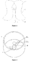
Figure 1 is a view showing the structure of an impeller of a cigarette according to an embodiment of the present application; -
Figure 2 is a view showing the structure of a shell of a cigarette according to an embodiment of the present application; -
Figure 3 is a view showing the structure of an impeller of a cigarette according to another embodiment of the present application; -
Figure 4 is a view showing the integral structure of a cigarette according to another embodiment of the present application. - A cigarette holder is provided according to the present application, in which an impeller stops rotating after the suction is stopped for 1 to 2.5 seconds, and an obvious vibration feel is generated when the impeller is rotating.
- The technical solution according to the embodiments of the present application will be described clearly and completely as follows in conjunction with the accompany drawings in the embodiments of the present application. It is obvious that the described embodiments are only a part of the embodiments according to the present application. All the other embodiments obtained by those skilled in the art based on the embodiments in the present application without any creative efforts fall into the scope of the present application.
- Referring to
Figure 1 and Figure 2 , the specific technical solution of a cigarette according to the present application is that: - the cigarette holder is a ternary composite holder, including a primary filter holder section, a filter and a secondary filter holder section in the listed sequence;
- the filter includes a
shell 3 and an impeller arranged inside theshell 3, the impeller includes acentral shaft 1 andblades 2 arranged on thecentral shaft 1; - an extension line of the
central shaft 1 extends toward the primary filter holder section and the secondary filter holder section. It should be understood that, in a case that the primary filter holder section, the filter and the secondary filter holder section are connected in the listed sequence and vertically arranged, thecentral shaft 1 is also vertically arranged; - the blade is composed of a
front end portion 21 and arear end portion 22 arranged front and back along a rotation track, and thefront end portion 21 is heavier than therear end portion 22. It should be understood that, theblade 2 rotates clockwise or anticlockwise by 360 degrees with respect to thecentral shaft 1, and thefront end portion 21 and therear end portion 22 are arranged according to the order of rotation. - Further, in order to reduce a resistance of the blade during rotation, each of the
front end portion 21 and therear end portion 22 is a continuous smooth curved surface. Preferably, a bending direction of thefront end portion 21 is opposite to a bending direction of therear end portion 22, making the blade in an S shape. - During the process that the impeller stops rotating, for making more obvious vibration feel for people, an edge of the
front end portion 21 and an edge of therear end portion 22 are located in different planes, and a projection area of theblade 2 is enlarged. Preferably, a height difference between the edge of thefront end portion 21 and the edge of therear end portion 22 is equal to or larger than 1/2 of a height of theshell 3. - For facilitating gas flow to pass through the primary filter holder section, the filter and the secondary filter holder section in the listed sequence, a side near an inner wall of the
shell 3 of thefront end portion 21 and therear end portion 22 is provided with a plurality of concave grooves arranged at intervals. - Moreover, in order to further facilitate the gas circulation and increase the vibration feel during the process of stopping rotation, the blade is arranged obliquely with respect to the central shaft, and meanwhile the
blades 2 are staggered. - Since the impeller according to the embodiment is arranged inside the
shell 3 and rotates inside theshell 3, thecentral shaft 1 of the impeller may be embodied as a hollow shaft, and asupport rod 34 for being inserted into the hollow shaft is arranged on theshell 3. For realizing the fixation of thesupport rod 34, thesupport rod 34 is fixed to amudsill 32 which is connected to the inner wall of the shell through abase 31. In order to increase the vibration feel during the rotation of the impeller, a diameter of thesupport rod 34 is between 1/3 and 2/3 of a diameter of a hole of thecentral shaft 1. During the suction, the gas flow exerts pressure from a windward side, an axis of the central shaft is not coincident with an axis of the support rod in the initial state of the impeller. Since the force on theblade 2 is uniform, swing along thesupport rod 34 is generated during the rotation. - Further, in order to prevent the impeller from sliding out of the
support rod 34 during the rotation of the impeller, an end of the support rod is provided with abulb 33 having a diameter greater than the diameter of the support rod. - Preferably, a sectional area of the
shell 3 increases gradually in a gas flowing direction. - The cigarette holder is a ternary composite holder, including a primary filter holder section, a filter and a secondary filter holder section in the listed sequence;
- the filter includes a
shell 3 and an impeller arranged inside theshell 3, the impeller includes acentral shaft 1 andblades 2 arranged on thecentral shaft 1; - an extension line of the
central shaft 1 extends toward the primary filter holder section and the secondary filter holder section. It should be understood that, in a case that the primary filter holder section, the filter and the secondary filter holder section are connected in a listed sequence and vertically arranged, thecentral shaft 1 is also vertically arranged; - the blade is composed of a
front end portion 21 and arear end portion 22, thefront end portion 21 and therear end portion 22 are symmetrical with respect to a central line of theblade 2 and form a triangle structure, and awindward side 224 of the triangle structure is arc shaped. Thefront end portion 21 is heavier than therear end portion 22. It should be understood that, theblade 2 rotates clockwise or anticlockwise by 360 degrees with respect to thecentral shaft 1. - Further, in order to reduce a resistance of the blade during rotation, each of the
front end portion 21 and therear end portion 22 is a continuous smooth curved surface. Preferably, thefront end portion 21 and therear end portion 22 are both bend inward, making the shape of theblade 2 in a U shape when viewed from the side. - During the process that the impeller stops rotating, for making more obvious vibration feel for people, an edge of the
front end portion 21 and an edge of therear end portion 22 are located in different planes, and a projection area of theblade 2 is enlarged. Preferably, a height difference between the edge of thefront end portion 21 and the edge of therear end portion 22 is equal to or larger than 1/2 of a height of theshell 3. - For facilitating the gas flow to pass through the primary filter holder section, the filter and the secondary filter holder section in the listed sequence, a
side 222 of the triangle structure is a deformation area. When the deformation area is heated, a deformation occurs, making a clearance between theside 222 and theshell 3 become larger, thereby increasing the amount of the gas flow. - A top surface and/or a bottom surface of the triangle structure is provided with a plurality of through holes for filling contents like medicines (such as citrus or eaglewood) or spices, to strengthen the aroma.
- Moreover, in order to further facilitate the gas circulation and increase the vibration feel during the process of stop rotating, the blade is arranged obliquely with respect to the central shaft, and meanwhile the blades are staggered.
- Since the impeller according to the embodiment is arranged inside the
shell 3 and rotates inside theshell 3, thecentral shaft 1 of the impeller may be a hollow shaft, and asupport rod 34 for being inserted into the hollow shaft is arranged on theshell 3. For realizing the fixation of thesupport rod 34, thesupport rod 34 is fixed to amudsill 32 which is connected to the inner wall of the shell through abase 31. In order to increase the vibration feel during the rotation of the impeller, a diameter of thesupport rod 34 is between 1/3 and 2/3 of a diameter of the hole of thecentral shaft 1. During the suction, the gas flow exerts pressure from a windward side, and an axis of the central shaft is not coincident with an axis of the support rod under the initial state of the impeller. Since the force on theblade 2 is uniform, swing along thesupport rod 34 is generated during the rotation. - Further, in order to prevent the impeller from sliding out of the
support rod 34 during the rotation of the impeller, an end of the support rod is provided with abulb 33 having a diameter larger than the diameter of the support rod. - Preferably, a sectional area of the
shell 3 increases gradually in a gas flowing direction. - A cigarette is also provided according to the present application, including the cigarettes corresponding to the
embodiment 1 andembodiment 2.
Claims (13)
- A cigarette holder, wherein the cigarette holder is a ternary composite holder, comprising a primary filter holder section, a filter and a secondary filter holder section in the listed sequence; andthe filter comprises a shell (3) and an impeller arranged inside the shell (3), the impeller comprises a central shaft (1) and a plurality of blades (2) arranged on the central shaft (1), an extension line of the central shaft (1) extends toward the primary filter holder section and the secondary filter holder section, each blade (2) is composed of a front end portion (21) and a rear end portion (22), and the front end portion (21) is heavier than the rear end portion (22); andcharacterised bya support rod (34) for being inserted into the central shaft (1) is arranged on a central axis of the shell (3), and an end of the support rod (34) is provided with a bulb (33) having a diameter larger than a diameter of the support rod (34).
- The cigarette holder according to claim 1, wherein each of the front end portion (21) and the rear end portion (22) is a continuous smooth curved surface, and an edge of the front end portion (21) and an edge of the rear end portion (22) are located in different planes.
- The cigarette holder according to claim 2, wherein the front end portion (21) and the rear end portion (22) are arranged front and back along a motion track of the blade (2), and a bending direction of the front end portion (21) is opposite to a bending direction of the rear end portion (22), making the blade (2) in an S shape.
- The cigarette holder according to claim3, wherein a height difference between an edge of the front end portion (21) and an edge of the rear end portion (22) is equal to or larger than 1/2 of a height of the shell (3).
- The cigarette holder according to claim 4, wherein sides near an inner wall of the shell (3) of the front end portion (21) and the rear end portion (22) are each provided with a plurality of concave grooves arranged at intervals.
- The cigarette holder according to claim 2, wherein each of the front end portion (21) and the rear end portion (22) is of a triangle structure having a cambered surface.
- The cigarette holder according to claim 6, wherein a side near the inner wall of the shell (3) of the triangle structure is a deformation area.
- The cigarette holder according to claim 6, wherein at least one of a top surface and a bottom surface of the triangle structure is provided with a plurality of through holes for filling contents.
- The cigarette holder according to any one of claims 1 to 8, wherein the blade (2) is arranged obliquely with respect to the central shaft (1).
- The cigarette holder according to any one of claims 1 to 8, wherein the blades (2) are staggered.
- The cigarette holder according to any one of claims 1 to 8, wherein a sectional area of the shell (3) increases gradually in a gas flowing direction.
- The cigarette holder according to claim 1, wherein the diameter of the support rod (34) is within a range between 1/3 and 2/3 of a diameter of a hole of the central shaft (1).
- A cigarette, comprising the cigarette holder according to any one of claims 1 to 12.
Applications Claiming Priority (1)
| Application Number | Priority Date | Filing Date | Title |
|---|---|---|---|
| CN201710967321.2A CN109662347A (en) | 2017-10-17 | 2017-10-17 | A kind of new cigarette mouth stick and cigarette |
Publications (2)
| Publication Number | Publication Date |
|---|---|
| EP3473114A1 EP3473114A1 (en) | 2019-04-24 |
| EP3473114B1 true EP3473114B1 (en) | 2023-03-22 |
Family
ID=60811959
Family Applications (1)
| Application Number | Title | Priority Date | Filing Date |
|---|---|---|---|
| EP17210521.5A Active EP3473114B1 (en) | 2017-10-17 | 2017-12-22 | Cigarette holder and cigarette |
Country Status (2)
| Country | Link |
|---|---|
| EP (1) | EP3473114B1 (en) |
| CN (1) | CN109662347A (en) |
Families Citing this family (1)
| Publication number | Priority date | Publication date | Assignee | Title |
|---|---|---|---|---|
| CN114652016A (en) * | 2022-04-15 | 2022-06-24 | 武汉沿程科技股份有限公司 | Cigarette capable of actively controlling smoke |
Citations (1)
| Publication number | Priority date | Publication date | Assignee | Title |
|---|---|---|---|---|
| EP2793625B1 (en) * | 2011-12-20 | 2017-09-27 | British American Tobacco (Investments) Limited | Smoking articles, and other flow delivery articles |
Family Cites Families (6)
| Publication number | Priority date | Publication date | Assignee | Title |
|---|---|---|---|---|
| US2797691A (en) * | 1955-04-04 | 1957-07-02 | Butler William | Cigarette filter |
| US3410273A (en) * | 1968-01-16 | 1968-11-12 | Bolles James Chadbourn | Cigarette |
| DE2430658A1 (en) * | 1974-06-26 | 1976-01-15 | Windgassen Dieter Dipl Kfm | Cigar or cigarette tip with mouthpiece and holder tube - has two impellers on spindle between holder tube and mouthpiece |
| US4184496A (en) * | 1978-02-23 | 1980-01-22 | Adair Virginia M | Air moving simulated cigarette device |
| CN2045936U (en) * | 1988-03-15 | 1989-10-18 | 郑广德 | Amusing poison-filtering tobacco pipe |
| CN105595419A (en) * | 2015-12-22 | 2016-05-25 | 贵州中烟工业有限责任公司 | Novel cigarette holder rod and cigarette |
-
2017
- 2017-10-17 CN CN201710967321.2A patent/CN109662347A/en active Pending
- 2017-12-22 EP EP17210521.5A patent/EP3473114B1/en active Active
Patent Citations (1)
| Publication number | Priority date | Publication date | Assignee | Title |
|---|---|---|---|---|
| EP2793625B1 (en) * | 2011-12-20 | 2017-09-27 | British American Tobacco (Investments) Limited | Smoking articles, and other flow delivery articles |
Also Published As
| Publication number | Publication date |
|---|---|
| EP3473114A1 (en) | 2019-04-24 |
| CN109662347A (en) | 2019-04-23 |
Similar Documents
| Publication | Publication Date | Title |
|---|---|---|
| US8758156B2 (en) | Golf club assembly and golf club with aerodynamic features | |
| CN105595419A (en) | Novel cigarette holder rod and cigarette | |
| EP3473114A1 (en) | Cigarette holder and cigarette | |
| JP2013502247A (en) | Inhalation device and method for inhaling active ingredients from capsules | |
| WO2023216326A1 (en) | Cartridge | |
| JP7212326B1 (en) | The draw resistance regulator and the cigarette bomb of the draw resistance regulator e-cigarette | |
| JP3235336U (en) | Draw Resistance Regulator and its Draw Resistance Regulator Electronic Cigarette Bomb | |
| CN206062121U (en) | A kind of flat mouth formula cigarette filter rod | |
| CN202265226U (en) | Flat-mouth paper sucking pipe with cambered surface | |
| CN205060346U (en) | Novel hand -held type distributor | |
| CN217852530U (en) | Fastener of waffle machine | |
| CN105986700B (en) | A kind of handle and the dish-washing machine with the handle | |
| CN207293058U (en) | Instant noodle barrel | |
| CN207261308U (en) | The stacked structure of axial-flow windwheel | |
| KR20200100508A (en) | Spout in a pouch container | |
| CN215383028U (en) | Daily glass wine decanter | |
| CN208531174U (en) | A kind of bottle cap | |
| CN204624301U (en) | A kind of down-drawable rotates plece-cliped type cigarette case | |
| CN209563827U (en) | A kind of brief Modern chair | |
| CN217937831U (en) | Safe tea cup not prone to dripping | |
| CN201879366U (en) | Suction tube | |
| CN206403093U (en) | A kind of convenient tea cake | |
| CN211532787U (en) | Novel circular electron cigarette | |
| CN206710945U (en) | A kind of laptop rotating shaft support | |
| CN208679718U (en) | Detection device for quick-fried pearl detection |
Legal Events
| Date | Code | Title | Description |
|---|---|---|---|
| PUAI | Public reference made under article 153(3) epc to a published international application that has entered the european phase |
Free format text: ORIGINAL CODE: 0009012 |
|
| STAA | Information on the status of an ep patent application or granted ep patent |
Free format text: STATUS: THE APPLICATION HAS BEEN PUBLISHED |
|
| AK | Designated contracting states |
Kind code of ref document: A1 Designated state(s): AL AT BE BG CH CY CZ DE DK EE ES FI FR GB GR HR HU IE IS IT LI LT LU LV MC MK MT NL NO PL PT RO RS SE SI SK SM TR |
|
| AX | Request for extension of the european patent |
Extension state: BA ME |
|
| STAA | Information on the status of an ep patent application or granted ep patent |
Free format text: STATUS: REQUEST FOR EXAMINATION WAS MADE |
|
| 17P | Request for examination filed |
Effective date: 20190812 |
|
| RBV | Designated contracting states (corrected) |
Designated state(s): AL AT BE BG CH CY CZ DE DK EE ES FI FR GB GR HR HU IE IS IT LI LT LU LV MC MK MT NL NO PL PT RO RS SE SI SK SM TR |
|
| GRAP | Despatch of communication of intention to grant a patent |
Free format text: ORIGINAL CODE: EPIDOSNIGR1 |
|
| STAA | Information on the status of an ep patent application or granted ep patent |
Free format text: STATUS: GRANT OF PATENT IS INTENDED |
|
| INTG | Intention to grant announced |
Effective date: 20221006 |
|
| GRAS | Grant fee paid |
Free format text: ORIGINAL CODE: EPIDOSNIGR3 |
|
| GRAA | (expected) grant |
Free format text: ORIGINAL CODE: 0009210 |
|
| STAA | Information on the status of an ep patent application or granted ep patent |
Free format text: STATUS: THE PATENT HAS BEEN GRANTED |
|
| AK | Designated contracting states |
Kind code of ref document: B1 Designated state(s): AL AT BE BG CH CY CZ DE DK EE ES FI FR GB GR HR HU IE IS IT LI LT LU LV MC MK MT NL NO PL PT RO RS SE SI SK SM TR |
|
| REG | Reference to a national code |
Ref country code: GB Ref legal event code: FG4D |
|
| REG | Reference to a national code |
Ref country code: CH Ref legal event code: EP |
|
| REG | Reference to a national code |
Ref country code: DE Ref legal event code: R096 Ref document number: 602017066981 Country of ref document: DE |
|
| REG | Reference to a national code |
Ref country code: IE Ref legal event code: FG4D |
|
| REG | Reference to a national code |
Ref country code: AT Ref legal event code: REF Ref document number: 1554743 Country of ref document: AT Kind code of ref document: T Effective date: 20230415 |
|
| REG | Reference to a national code |
Ref country code: LT Ref legal event code: MG9D |
|
| REG | Reference to a national code |
Ref country code: NL Ref legal event code: MP Effective date: 20230322 |
|
| PG25 | Lapsed in a contracting state [announced via postgrant information from national office to epo] |
Ref country code: RS Free format text: LAPSE BECAUSE OF FAILURE TO SUBMIT A TRANSLATION OF THE DESCRIPTION OR TO PAY THE FEE WITHIN THE PRESCRIBED TIME-LIMIT Effective date: 20230322 Ref country code: NO Free format text: LAPSE BECAUSE OF FAILURE TO SUBMIT A TRANSLATION OF THE DESCRIPTION OR TO PAY THE FEE WITHIN THE PRESCRIBED TIME-LIMIT Effective date: 20230622 Ref country code: LV Free format text: LAPSE BECAUSE OF FAILURE TO SUBMIT A TRANSLATION OF THE DESCRIPTION OR TO PAY THE FEE WITHIN THE PRESCRIBED TIME-LIMIT Effective date: 20230322 Ref country code: LT Free format text: LAPSE BECAUSE OF FAILURE TO SUBMIT A TRANSLATION OF THE DESCRIPTION OR TO PAY THE FEE WITHIN THE PRESCRIBED TIME-LIMIT Effective date: 20230322 Ref country code: HR Free format text: LAPSE BECAUSE OF FAILURE TO SUBMIT A TRANSLATION OF THE DESCRIPTION OR TO PAY THE FEE WITHIN THE PRESCRIBED TIME-LIMIT Effective date: 20230322 |
|
| REG | Reference to a national code |
Ref country code: AT Ref legal event code: MK05 Ref document number: 1554743 Country of ref document: AT Kind code of ref document: T Effective date: 20230322 |
|
| PG25 | Lapsed in a contracting state [announced via postgrant information from national office to epo] |
Ref country code: SE Free format text: LAPSE BECAUSE OF FAILURE TO SUBMIT A TRANSLATION OF THE DESCRIPTION OR TO PAY THE FEE WITHIN THE PRESCRIBED TIME-LIMIT Effective date: 20230322 Ref country code: NL Free format text: LAPSE BECAUSE OF FAILURE TO SUBMIT A TRANSLATION OF THE DESCRIPTION OR TO PAY THE FEE WITHIN THE PRESCRIBED TIME-LIMIT Effective date: 20230322 Ref country code: GR Free format text: LAPSE BECAUSE OF FAILURE TO SUBMIT A TRANSLATION OF THE DESCRIPTION OR TO PAY THE FEE WITHIN THE PRESCRIBED TIME-LIMIT Effective date: 20230623 Ref country code: FI Free format text: LAPSE BECAUSE OF FAILURE TO SUBMIT A TRANSLATION OF THE DESCRIPTION OR TO PAY THE FEE WITHIN THE PRESCRIBED TIME-LIMIT Effective date: 20230322 |
|
| PG25 | Lapsed in a contracting state [announced via postgrant information from national office to epo] |
Ref country code: SM Free format text: LAPSE BECAUSE OF FAILURE TO SUBMIT A TRANSLATION OF THE DESCRIPTION OR TO PAY THE FEE WITHIN THE PRESCRIBED TIME-LIMIT Effective date: 20230322 Ref country code: RO Free format text: LAPSE BECAUSE OF FAILURE TO SUBMIT A TRANSLATION OF THE DESCRIPTION OR TO PAY THE FEE WITHIN THE PRESCRIBED TIME-LIMIT Effective date: 20230322 Ref country code: PT Free format text: LAPSE BECAUSE OF FAILURE TO SUBMIT A TRANSLATION OF THE DESCRIPTION OR TO PAY THE FEE WITHIN THE PRESCRIBED TIME-LIMIT Effective date: 20230724 Ref country code: ES Free format text: LAPSE BECAUSE OF FAILURE TO SUBMIT A TRANSLATION OF THE DESCRIPTION OR TO PAY THE FEE WITHIN THE PRESCRIBED TIME-LIMIT Effective date: 20230322 Ref country code: EE Free format text: LAPSE BECAUSE OF FAILURE TO SUBMIT A TRANSLATION OF THE DESCRIPTION OR TO PAY THE FEE WITHIN THE PRESCRIBED TIME-LIMIT Effective date: 20230322 Ref country code: AT Free format text: LAPSE BECAUSE OF FAILURE TO SUBMIT A TRANSLATION OF THE DESCRIPTION OR TO PAY THE FEE WITHIN THE PRESCRIBED TIME-LIMIT Effective date: 20230322 |
|
| PG25 | Lapsed in a contracting state [announced via postgrant information from national office to epo] |
Ref country code: SK Free format text: LAPSE BECAUSE OF FAILURE TO SUBMIT A TRANSLATION OF THE DESCRIPTION OR TO PAY THE FEE WITHIN THE PRESCRIBED TIME-LIMIT Effective date: 20230322 Ref country code: PL Free format text: LAPSE BECAUSE OF FAILURE TO SUBMIT A TRANSLATION OF THE DESCRIPTION OR TO PAY THE FEE WITHIN THE PRESCRIBED TIME-LIMIT Effective date: 20230322 Ref country code: IS Free format text: LAPSE BECAUSE OF FAILURE TO SUBMIT A TRANSLATION OF THE DESCRIPTION OR TO PAY THE FEE WITHIN THE PRESCRIBED TIME-LIMIT Effective date: 20230722 |
|
| REG | Reference to a national code |
Ref country code: DE Ref legal event code: R097 Ref document number: 602017066981 Country of ref document: DE |
|
| PLBE | No opposition filed within time limit |
Free format text: ORIGINAL CODE: 0009261 |
|
| STAA | Information on the status of an ep patent application or granted ep patent |
Free format text: STATUS: NO OPPOSITION FILED WITHIN TIME LIMIT |
|
| PG25 | Lapsed in a contracting state [announced via postgrant information from national office to epo] |
Ref country code: SI Free format text: LAPSE BECAUSE OF FAILURE TO SUBMIT A TRANSLATION OF THE DESCRIPTION OR TO PAY THE FEE WITHIN THE PRESCRIBED TIME-LIMIT Effective date: 20230322 Ref country code: DK Free format text: LAPSE BECAUSE OF FAILURE TO SUBMIT A TRANSLATION OF THE DESCRIPTION OR TO PAY THE FEE WITHIN THE PRESCRIBED TIME-LIMIT Effective date: 20230322 Ref country code: CZ Free format text: LAPSE BECAUSE OF FAILURE TO SUBMIT A TRANSLATION OF THE DESCRIPTION OR TO PAY THE FEE WITHIN THE PRESCRIBED TIME-LIMIT Effective date: 20230322 |
|
| 26N | No opposition filed |
Effective date: 20240102 |
|
| PG25 | Lapsed in a contracting state [announced via postgrant information from national office to epo] |
Ref country code: IT Free format text: LAPSE BECAUSE OF FAILURE TO SUBMIT A TRANSLATION OF THE DESCRIPTION OR TO PAY THE FEE WITHIN THE PRESCRIBED TIME-LIMIT Effective date: 20230322 |
|
| REG | Reference to a national code |
Ref country code: CH Ref legal event code: PL |
|
| PG25 | Lapsed in a contracting state [announced via postgrant information from national office to epo] |
Ref country code: LU Free format text: LAPSE BECAUSE OF NON-PAYMENT OF DUE FEES Effective date: 20231222 |
|
| PG25 | Lapsed in a contracting state [announced via postgrant information from national office to epo] |
Ref country code: MC Free format text: LAPSE BECAUSE OF FAILURE TO SUBMIT A TRANSLATION OF THE DESCRIPTION OR TO PAY THE FEE WITHIN THE PRESCRIBED TIME-LIMIT Effective date: 20230322 |
|
| GBPC | Gb: european patent ceased through non-payment of renewal fee |
Effective date: 20231222 |
|
| REG | Reference to a national code |
Ref country code: BE Ref legal event code: MM Effective date: 20231231 |
|
| PG25 | Lapsed in a contracting state [announced via postgrant information from national office to epo] |
Ref country code: MC Free format text: LAPSE BECAUSE OF FAILURE TO SUBMIT A TRANSLATION OF THE DESCRIPTION OR TO PAY THE FEE WITHIN THE PRESCRIBED TIME-LIMIT Effective date: 20230322 Ref country code: LU Free format text: LAPSE BECAUSE OF NON-PAYMENT OF DUE FEES Effective date: 20231222 |
|
| REG | Reference to a national code |
Ref country code: IE Ref legal event code: MM4A |
|
| PG25 | Lapsed in a contracting state [announced via postgrant information from national office to epo] |
Ref country code: IE Free format text: LAPSE BECAUSE OF NON-PAYMENT OF DUE FEES Effective date: 20231222 |
|
| PG25 | Lapsed in a contracting state [announced via postgrant information from national office to epo] |
Ref country code: GB Free format text: LAPSE BECAUSE OF NON-PAYMENT OF DUE FEES Effective date: 20231222 |
|
| PG25 | Lapsed in a contracting state [announced via postgrant information from national office to epo] |
Ref country code: BE Free format text: LAPSE BECAUSE OF NON-PAYMENT OF DUE FEES Effective date: 20231231 |
|
| PG25 | Lapsed in a contracting state [announced via postgrant information from national office to epo] |
Ref country code: CH Free format text: LAPSE BECAUSE OF NON-PAYMENT OF DUE FEES Effective date: 20231231 |
|
| PG25 | Lapsed in a contracting state [announced via postgrant information from national office to epo] |
Ref country code: IE Free format text: LAPSE BECAUSE OF NON-PAYMENT OF DUE FEES Effective date: 20231222 Ref country code: GB Free format text: LAPSE BECAUSE OF NON-PAYMENT OF DUE FEES Effective date: 20231222 Ref country code: CH Free format text: LAPSE BECAUSE OF NON-PAYMENT OF DUE FEES Effective date: 20231231 Ref country code: BE Free format text: LAPSE BECAUSE OF NON-PAYMENT OF DUE FEES Effective date: 20231231 |
|
| PG25 | Lapsed in a contracting state [announced via postgrant information from national office to epo] |
Ref country code: BG Free format text: LAPSE BECAUSE OF FAILURE TO SUBMIT A TRANSLATION OF THE DESCRIPTION OR TO PAY THE FEE WITHIN THE PRESCRIBED TIME-LIMIT Effective date: 20230322 |
|
| PG25 | Lapsed in a contracting state [announced via postgrant information from national office to epo] |
Ref country code: BG Free format text: LAPSE BECAUSE OF FAILURE TO SUBMIT A TRANSLATION OF THE DESCRIPTION OR TO PAY THE FEE WITHIN THE PRESCRIBED TIME-LIMIT Effective date: 20230322 |
|
| PG25 | Lapsed in a contracting state [announced via postgrant information from national office to epo] |
Ref country code: CY Free format text: LAPSE BECAUSE OF FAILURE TO SUBMIT A TRANSLATION OF THE DESCRIPTION OR TO PAY THE FEE WITHIN THE PRESCRIBED TIME-LIMIT; INVALID AB INITIO Effective date: 20171222 |
|
| PG25 | Lapsed in a contracting state [announced via postgrant information from national office to epo] |
Ref country code: HU Free format text: LAPSE BECAUSE OF FAILURE TO SUBMIT A TRANSLATION OF THE DESCRIPTION OR TO PAY THE FEE WITHIN THE PRESCRIBED TIME-LIMIT; INVALID AB INITIO Effective date: 20171222 |
|
| PG25 | Lapsed in a contracting state [announced via postgrant information from national office to epo] |
Ref country code: TR Free format text: LAPSE BECAUSE OF FAILURE TO SUBMIT A TRANSLATION OF THE DESCRIPTION OR TO PAY THE FEE WITHIN THE PRESCRIBED TIME-LIMIT Effective date: 20230322 |
|
| PGFP | Annual fee paid to national office [announced via postgrant information from national office to epo] |
Ref country code: FR Payment date: 20251230 Year of fee payment: 9 |
|
| PGFP | Annual fee paid to national office [announced via postgrant information from national office to epo] |
Ref country code: DE Payment date: 20251231 Year of fee payment: 9 |