EP3472754B1 - Communication arrangement to electrically connect a slave to a host device - Google Patents
Communication arrangement to electrically connect a slave to a host device Download PDFInfo
- Publication number
- EP3472754B1 EP3472754B1 EP17815805.1A EP17815805A EP3472754B1 EP 3472754 B1 EP3472754 B1 EP 3472754B1 EP 17815805 A EP17815805 A EP 17815805A EP 3472754 B1 EP3472754 B1 EP 3472754B1
- Authority
- EP
- European Patent Office
- Prior art keywords
- electronic
- communication apparatus
- slave device
- smart card
- fingerprint
- Prior art date
- Legal status (The legal status is an assumption and is not a legal conclusion. Google has not performed a legal analysis and makes no representation as to the accuracy of the status listed.)
- Active
Links
Images


Classifications
-
- H—ELECTRICITY
- H04—ELECTRIC COMMUNICATION TECHNIQUE
- H04L—TRANSMISSION OF DIGITAL INFORMATION, e.g. TELEGRAPHIC COMMUNICATION
- H04L9/00—Cryptographic mechanisms or cryptographic arrangements for secret or secure communications; Network security protocols
- H04L9/32—Cryptographic mechanisms or cryptographic arrangements for secret or secure communications; Network security protocols including means for verifying the identity or authority of a user of the system or for message authentication, e.g. authorization, entity authentication, data integrity or data verification, non-repudiation, key authentication or verification of credentials
- H04L9/3234—Cryptographic mechanisms or cryptographic arrangements for secret or secure communications; Network security protocols including means for verifying the identity or authority of a user of the system or for message authentication, e.g. authorization, entity authentication, data integrity or data verification, non-repudiation, key authentication or verification of credentials involving additional secure or trusted devices, e.g. TPM, smartcard, USB or software token
-
- G—PHYSICS
- G06—COMPUTING OR CALCULATING; COUNTING
- G06F—ELECTRIC DIGITAL DATA PROCESSING
- G06F21/00—Security arrangements for protecting computers, components thereof, programs or data against unauthorised activity
- G06F21/30—Authentication, i.e. establishing the identity or authorisation of security principals
- G06F21/31—User authentication
- G06F21/34—User authentication involving the use of external additional devices, e.g. dongles or smart cards
-
- H—ELECTRICITY
- H01—ELECTRIC ELEMENTS
- H01B—CABLES; CONDUCTORS; INSULATORS; SELECTION OF MATERIALS FOR THEIR CONDUCTIVE, INSULATING OR DIELECTRIC PROPERTIES
- H01B7/00—Insulated conductors or cables characterised by their form
- H01B7/08—Flat or ribbon cables
- H01B7/0892—Flat or ribbon cables incorporated in a cable of non-flat configuration
-
- H—ELECTRICITY
- H01—ELECTRIC ELEMENTS
- H01R—ELECTRICALLY-CONDUCTIVE CONNECTIONS; STRUCTURAL ASSOCIATIONS OF A PLURALITY OF MUTUALLY-INSULATED ELECTRICAL CONNECTING ELEMENTS; COUPLING DEVICES; CURRENT COLLECTORS
- H01R13/00—Details of coupling devices of the kinds covered by groups H01R12/70 or H01R24/00 - H01R33/00
- H01R13/46—Bases; Cases
- H01R13/502—Bases; Cases composed of different pieces
- H01R13/506—Bases; Cases composed of different pieces assembled by snap action of the parts
-
- H—ELECTRICITY
- H01—ELECTRIC ELEMENTS
- H01R—ELECTRICALLY-CONDUCTIVE CONNECTIONS; STRUCTURAL ASSOCIATIONS OF A PLURALITY OF MUTUALLY-INSULATED ELECTRICAL CONNECTING ELEMENTS; COUPLING DEVICES; CURRENT COLLECTORS
- H01R13/00—Details of coupling devices of the kinds covered by groups H01R12/70 or H01R24/00 - H01R33/00
- H01R13/646—Details of coupling devices of the kinds covered by groups H01R12/70 or H01R24/00 - H01R33/00 specially adapted for high-frequency, e.g. structures providing an impedance match or phase match
- H01R13/6461—Means for preventing cross-talk
- H01R13/6463—Means for preventing cross-talk using twisted pairs of wires
-
- H—ELECTRICITY
- H01—ELECTRIC ELEMENTS
- H01R—ELECTRICALLY-CONDUCTIVE CONNECTIONS; STRUCTURAL ASSOCIATIONS OF A PLURALITY OF MUTUALLY-INSULATED ELECTRICAL CONNECTING ELEMENTS; COUPLING DEVICES; CURRENT COLLECTORS
- H01R13/00—Details of coupling devices of the kinds covered by groups H01R12/70 or H01R24/00 - H01R33/00
- H01R13/646—Details of coupling devices of the kinds covered by groups H01R12/70 or H01R24/00 - H01R33/00 specially adapted for high-frequency, e.g. structures providing an impedance match or phase match
- H01R13/6461—Means for preventing cross-talk
- H01R13/6464—Means for preventing cross-talk by adding capacitive elements
- H01R13/6466—Means for preventing cross-talk by adding capacitive elements on substrates, e.g. printed circuit boards [PCB]
-
- H—ELECTRICITY
- H01—ELECTRIC ELEMENTS
- H01R—ELECTRICALLY-CONDUCTIVE CONNECTIONS; STRUCTURAL ASSOCIATIONS OF A PLURALITY OF MUTUALLY-INSULATED ELECTRICAL CONNECTING ELEMENTS; COUPLING DEVICES; CURRENT COLLECTORS
- H01R13/00—Details of coupling devices of the kinds covered by groups H01R12/70 or H01R24/00 - H01R33/00
- H01R13/66—Structural association with built-in electrical component
- H01R13/665—Structural association with built-in electrical component with built-in electronic circuit
-
- H—ELECTRICITY
- H04—ELECTRIC COMMUNICATION TECHNIQUE
- H04L—TRANSMISSION OF DIGITAL INFORMATION, e.g. TELEGRAPHIC COMMUNICATION
- H04L9/00—Cryptographic mechanisms or cryptographic arrangements for secret or secure communications; Network security protocols
- H04L9/32—Cryptographic mechanisms or cryptographic arrangements for secret or secure communications; Network security protocols including means for verifying the identity or authority of a user of the system or for message authentication, e.g. authorization, entity authentication, data integrity or data verification, non-repudiation, key authentication or verification of credentials
- H04L9/3226—Cryptographic mechanisms or cryptographic arrangements for secret or secure communications; Network security protocols including means for verifying the identity or authority of a user of the system or for message authentication, e.g. authorization, entity authentication, data integrity or data verification, non-repudiation, key authentication or verification of credentials using a predetermined code, e.g. password, passphrase or PIN
- H04L9/3231—Biological data, e.g. fingerprint, voice or retina
-
- H—ELECTRICITY
- H04—ELECTRIC COMMUNICATION TECHNIQUE
- H04L—TRANSMISSION OF DIGITAL INFORMATION, e.g. TELEGRAPHIC COMMUNICATION
- H04L2209/00—Additional information or applications relating to cryptographic mechanisms or cryptographic arrangements for secret or secure communication H04L9/00
- H04L2209/50—Oblivious transfer
Definitions
- the present invention relates to a communication apparatus configured to allow wired communication between an electronic host device and an electrical slave device, such as between a smart phone and a smart card during an enrollment process.
- Biometric techniques to identify and/or authenticate the identity of a user
- Biometric techniques that are promoted for this use include voice, fingerprint, iris, vein pattern and other scans.
- fingerprint sensors for capturing a fingerprint has shown to be specifically promising, for example due to its ease of integration with different types of electronic equipment, such as smartphones, watches, tablets, or any other type of electronic devices where personalized user interaction is advantageous.
- the electronic equipment is generally provided with some form of graphical user interface (GUI) for instructing the user on how to start using the functionality provided by means of the fingerprint sensor.
- GUI graphical user interface
- the GUI may be specifically adapted to instruct the user on how to enroll a finger for allowing future authentication of the user.
- electronic equipment that lacks a GUI for providing suitable instructions to the user during the enrollment process. In such a case, the enrollment process as well as the general use of the fingerprint sensor may introduce an undue burden to the user.
- an external device such as a smart card reader may be used for providing messages to guide the user through the enrollment process while using the fingerprint sensor on the smart card.
- the external device should be kept secure, thereby not allowing a person who comes into unauthorized possession of the smart card to replace the authorized user's biometric data with the unauthorized user's biometric data.
- the biometric input may be a sensor pad on the transaction authentication card that measures blood flow patterns, temperature, and/or fingerprint patterns to identify a user to permit access.
- the transaction authentication card is preferably substantially rigid, but may be formed to have some flexibility. Power to the transaction authentication card may be accomplished through an internal battery that is optionally rechargeable.
- Biometric data is stored on the card only and used for user verification. Biometric data will not be transferred from the card. If authorized biometric data is authenticated the card will transmit a wireless access code to a proximity reader or transaction equipment.
- a high security identification card includes an on-board memory for stored biometric data and an on-board sensor for capturing live biometric data.
- An on-board processor on the card performs a matching operation to verify that the captured biometric data matches the locally stored biometric data. Only if there is a positive match is any data transmitted from the card for additional verification and/or further processing.
- an electronic slave device By means of the invention, it is possible to provide a simple and intuitive apparatus that allows an electronic equipment having an embedded fingerprint sensor but lacking a suitable user interface, above denoted as an electronic slave device, to be connected to e.g. a smartphone, above denoted as an electronic host device, where the electronic host device will be in control of the operation of the fingerprint sensor provided at the electronic slave device.
- the communication apparatus is preferably provided together with the electronic slave device, advantageously already connected to the contact pads of the electronic slave device.
- the physical interface comprises for example a USB connector, allowing for example the electronic slave device to be arranged in wired communication with the electronic host device, through a standard port provided with the electronic host device.
- a USB connector allowing for example the electronic slave device to be arranged in wired communication with the electronic host device, through a standard port provided with the electronic host device.
- Any other form of universal connector may of course be provided, being within the scope of the present invention.
- the electronic host may in one embodiment be a smart phone, where the smartphone is provided with e.g. a USB interface for allowing wired communication as well as for charging the smart phone.
- the USB interface of the smartphone may thus be connected to the USB interface of the communication apparatus.
- the cable as mentioned above is in accordance to the present invention a flexible printed circuit, and the control unit could is integrated with the flexible printed circuit. Due to the cable being a flexible printed circuit, it is possible to manufacture the communication apparatus to be both light and cheap. In addition, the flexibility will allow the communication apparatus be easily packed and distributed together with the electronic slave device, allowing the total cost of the combination of the electronic host device and the communication apparatus to be in comparison low.
- the communication apparatus typically is provided without any form of user interface for providing any form of messages to the user, but that such messages rather are provided by means of an already available electronic host device, for example being one of the above mentioned smartphone, a tablet, a laptop, etc.
- fingerprint representation (or fingerprint image) should be interpreted broadly and to include both a regular “visual image” of a fingerprint of a finger as well as a set of measurements relating to the finger when acquired using the fingerprint sensor. A plurality of fingerprint images may be subsequently acquired and fused together, where the resulting information is used as an input for determining the sets of features.
- the electronic slave device is a smart card, for example a hybrid smart card.
- the connector is in such an embodiment preferably configured to match the physical configuration of the standard contact pads comprised with the smart card.
- the connector is preferably provided with an adhesive element for securely connecting the connector of the communication apparatus to the contact pads of the smart card.
- an un-programmed (“new") smart card may be delivered to a user (e.g. by post from an issuing party), having the communication apparatus already connected to the contact pads of the smart card.
- the user may connect the physical interface, e.g. being the above mentioned USB connector, to his smartphone.
- the smartphone may in turn be equipped with an application (“App") providing the user with instruction as how to enroll his fingerprint with the smart card.
- the connector may be peeled off (being adhesive) from the contact pads and the smart card may be used as a stand-alone device.
- the communication apparatus may in then be discarded.
- the smart card further comprises a wireless transceiver, for example adapted for at least one of Wi-Fi, Bluetooth, and NFC communication.
- the wireless functionality could for example be used once the user has enrolled his fingerprint with the smart card, for example for payment purposes as is known within the technical area of the invention.
- the control unit comprises means for automatically initiating communication between the fingerprint sensor and the electronic host device.
- the control unit can be arranged to automatically activate the app for fingerprint enrollment once the control unit of the communication apparatus has established the wired connection to the smartphone.
- the control unit has stored program code for the app to be executed at the smartphone and will accordingly transfer the stored program code to the smartphone once the wired connection has been established.
- the control unit may provide e.g. an Internet link to the smartphone for initiating downloading of the adequate app to the smartphone.
- At least one of the control unit and processing circuitry comprised with the smart card is configured to receive and validate authentication information provided from the electronic host device and only enter into an enrollment process if the authentication information is successfully validated. Accordingly, the user may be instructed to enter a previously provided (e.g. by a postal or electronic letter, or similar, provided separately from the delivery of the smart card) piece of authentication information before the process proceeds to allow the user to enroll his finger with the electronic slave device.
- a further security level is provided by means of the synergetic effect achieved by means of the combination of the electronic host device, the electronic slave device and the communication apparatus.
- the authentication information may for example be a PIN code or a password, to be entered within the GUI provided at the electronic host device.
- the communication apparatus is preferably provided as a component of smart card system further comprising an electronic slave device in the form of a smart card comprising the above mentioned contact pads.
- the smart card system may typically be delivered to an end user as a kit of parts where the communication apparatus is pre-connected to the smart card, arranged for future detachment.
- the fingerprint sensor preferably is a fingerprint touch sensor; however the invention may also be implemented using e.g. a swipe fingerprint sensor.
- the fingerprint sensor may be implemented using any kind of current or future fingerprint sensing principle, including for example capacitive, optical, or thermal sensing technology. However, at present capacitive sensing is most preferred. Both one and two-dimensional sensors are possible and within the scope of the invention.
- fingerprint data should be interpreted broadly and to include both a regular “visual image” of a fingerprint of a finger as well as a set of measurements relating to the finger when acquired using the fingerprint sensor. A plurality of fingerprint images may be subsequently acquired and fused together, where the resulting information is used as an input for determining sets of fingerprint features.
- processing circuitry should be understood to include any type of computing device, such as an ASIC, a micro-processor, etc. It should also be understood that the actual implementation of such a processing circuitry may be divided between more than a single device/circuit.
- the communication apparatus is "locked" once the enrollment process has completed. Accordingly, the communication apparatus may be safely discarded, securing that no further use is allowed, even by the rightful user.
- the same account for the smart card which may additionally be locked once the enrollment process has completed. It should be understood that locking also may be done in case authentication attempts failed reaches an unacceptable level.
- the communication apparatus 100 comprises a cable 102, a connector 104 provided a first end 106 of the cable 102 and arranged to be detachably connected to contact pads comprised with an electronic slave device as will be further discussed below.
- the connector 104 in turn comprises electrical connection elements 108 provided with adhesive portions 110 for secure connection to the contact pads of the electronic slave device.
- the communication apparatus 100 comprises a control unit 112 electrically connected to a second end 114 of the cable 102, and a physical interface 116 for allowing the control unit 112 to be electrically connected to an electronic host device as will be further exemplified in Fig. 2 .
- the physical interface 116 may in some embodiment be an USB "plug", mini USB plug, USB-C plug, etc.
- control unit 112 typically includes functionality for converting signals from UART to USB or from USB to UART. Such functionality may possibly also be provided by means of an additional chip or as integrated with the control unit 112.
- control unit 112 may be unified with the physical interface 116 to form a single body for minimization.
- the general functionality for signal conversion may as understood, be performed differently, still within the scope of the invention.
- other protocols may be possible in line with the present invention.
- Fig. 2 there is provided an example of use of the communication apparatus 100 for providing a wired connection between a mobile phone (e.g. a so called "smartphone") 202 and a smart card 204.
- a mobile phone e.g. a so called "smartphone”
- the smartphone 202 comprises a display unit 206 with a touch screen interface.
- the smartphone 202 further comprises a first antenna for WLAN/Wi-Fi communication, a second antenna for telecommunication communication, a microphone, a speaker, and a phone control unit.
- Further hardware elements are of course possibly comprised with the mobile phone. It should furthermore be noted that the invention may be applicable in relation to any other type of portable electronic device, such as a laptop, a remote control, a tablet computer, or any other type of present or future similarly configured device.
- the smartphone 202 further comprises an interface 216, a "socket", correspondingly adapted for receiving the plug of the physical interface 116.
- the smart card 204 is provided with a fingerprint sensing system including a fingerprint sensor 208 having an array of pixels and configured for capturing a fingerprint representation of a fingerprint pattern of a finger of a user and processing circuitry 210 connected to and configured to control the operation of the fingerprint sensor 208.
- the fingerprint sensor 208 is arranged on the front side of the smart card 204.
- the fingerprint sensor 208 may as an alternative (or also) be provided on a back side of the smart card 204.
- the fingerprint sensor 208 may, for example, be used for authenticating the user when performing a payment/transaction, for example allowing the smart card 204, once the finger of the user has been enrolled, to interact with a POS terminal (not shown).
- the smart card 204 comprises a plurality of contact pads 212 electrically connected to at least the processing circuitry 210.
- the smart card 204 forms together with the communication apparatus 100 a smart card system 214.
- the processing circuitry 210 further comprises a memory, such as a database, e.g. for storing one or a plurality of fingerprint template for one or a plurality of fingers for the user.
- the processing circuitry 210 may each include a microprocessor, microcontroller, programmable digital signal processor or another programmable device.
- the processing circuitry 210 may also, or instead, each include an application specific integrated circuit, a programmable gate array or programmable array logic, a programmable logic device, or a digital signal processor.
- the processor may further include computer executable code that controls operation of the programmable device. It should be understood that all or some parts of the functionality provided by means of the processing circuitry 210 (or generally discussed as "processing circuitry”) may be at least partly integrated with the fingerprint sensor 208.
- the fingerprint sensor 208 is configured to comprise a large plurality of sensing elements, preferably arranged as a two-dimensional array.
- the two-dimensional array may have sizes depending on the planned implementation and in an embodiment 160x160 pixels are used. Other sizes are of course possible and within the scope of the invention, including two-dimensional array with less pixels as compared to the above example.
- a single sensing element (also denoted as a pixel) is in Fig. 3 indicated by reference numeral 302.
- FIG. 4a A further example of use of the communication apparatus 100 is shown in Fig. 4a .
- the communication apparatus 100 is provided to connect an electronic slave device in the form of a toaster 402 to an electronic host device in the form of a tablet 404.
- the communication apparatus 100 is provided to connect an electronic slave device in the form of a light button 406 to an electronic host device in the form of a laptop 408.
- any type of electronic slave device i.e.
- an electronic device comprising a fingerprint sensing system but lacking a suitable user interface for enrolling a finger of a user
- a wired connection using the communication apparatus 100
- the communication apparatus 100 is typically detected from the electronic host device and removed (e.g. by pealing of the adhesive connector from contact pads) of the electronic slave device.
- a connection for data communication is established, S1, between the fingerprint sensing system of the smart card 204 and an electronic host device, such as the smartphone 202.
- the connection is preferably provided using the above disclosed communication apparatus 100, but could alternatively be provided using the wireless connection between e.g. the smartphone 202 and the smart card 204, e.g. using NFC, Wi-Fi, etc.
- the user will be provided, S2, with an instruction to enter e.g. the above mentioned PIN number as a piece of authentication information, within a user interface provided using the display 206 of the smartphone 202.
- the authentication information is validated, S3, typically involving information pre-stored to the smart card 204.
- the validation may also involve communication between the smartphone 202 and a remotely arranged server (not shown), for authenticating the user.
- the user is further provided, S4, with an instruction to position the finger at the fingerprint sensor 208.
- the instruction may for example include guidance as how the finger is to be positioned, re-positioned in case of a non-correct positioning, etc.
- a fingerprint image is acquired, S5, using the fingerprint sensor 208.
- the processing circuitry 210 provided with the smart card 204 will then extract, S6, extracting fingerprint features from the fingerprint image and form, S7, a fingerprint template for user authentication based on the extracted fingerprint features.
- the fingerprint template is stored, S8, within a digital memory comprised with the smart card 204.
- the user interface is provided within an app of the smartphone 202, and the app will also inform once a successful enrollment of the finger has been completed.
- the smart card 204 and/or the communication apparatus 100 is subsequently locked from any further use, e.g. for re-enrollment or for us with a different electronic slave device.
- the smart card 204 and/or the communication apparatus 100 may be locked in case the validation of e.g. the PIN has failed (more than a preselected number of times), or due to other reasons.
- the app may in some embodiments be a native app provided with the electronic host device, or to be downloaded when needed, for example from the control unit 112, from the processing circuitry 210, or from a remote server (such as an "app store"). Downloading of the app to the smartphone 202 may be automatic, e.g. initiated once the data communication has been established between the smartphone 202 and the smart card 204.
- control functionality of the present disclosure may be implemented using existing computer processors, or by a special purpose computer processor for an appropriate system, incorporated for this or another purpose, or by a hardwire system.
- Embodiments within the scope of the present disclosure include program products comprising machine-readable medium for carrying or having machine-executable instructions or data structures stored thereon.
- Such machine-readable media can be any available media that can be accessed by a general purpose or special purpose computer or other machine with a processor.
- machine-readable media can comprise RAM, ROM, EPROM, EEPROM, CD-ROM or other optical disk storage, magnetic disk storage or other magnetic storage devices, or any other medium which can be used to carry or store desired program code in the form of machine-executable instructions or data structures and which can be accessed by a general purpose or special purpose computer or other machine with a processor.
- a network or another communications connection either hardwired, wireless, or a combination of hardwired or wireless
- any such connection is properly termed a machine-readable medium.
- Machine-executable instructions include, for example, instructions and data which cause a general purpose computer, special purpose computer, or special purpose processing machines to perform a certain function or group of functions.
Landscapes
- Engineering & Computer Science (AREA)
- Computer Security & Cryptography (AREA)
- Computer Networks & Wireless Communication (AREA)
- Signal Processing (AREA)
- General Health & Medical Sciences (AREA)
- Life Sciences & Earth Sciences (AREA)
- Biodiversity & Conservation Biology (AREA)
- Biomedical Technology (AREA)
- Health & Medical Sciences (AREA)
- Microelectronics & Electronic Packaging (AREA)
- Theoretical Computer Science (AREA)
- Software Systems (AREA)
- Physics & Mathematics (AREA)
- General Engineering & Computer Science (AREA)
- General Physics & Mathematics (AREA)
- Computer Hardware Design (AREA)
- Telephone Function (AREA)
- Image Input (AREA)
- Measurement Of The Respiration, Hearing Ability, Form, And Blood Characteristics Of Living Organisms (AREA)
Description
- The present invention relates to a communication apparatus configured to allow wired communication between an electronic host device and an electrical slave device, such as between a smart phone and a smart card during an enrollment process.
- The use of biometric techniques to identify and/or authenticate the identity of a user is increasing. Biometric techniques that are promoted for this use include voice, fingerprint, iris, vein pattern and other scans. Currently, the use of fingerprint sensors for capturing a fingerprint has shown to be specifically promising, for example due to its ease of integration with different types of electronic equipment, such as smartphones, watches, tablets, or any other type of electronic devices where personalized user interaction is advantageous.
- In the above typical prior art examples of electronic equipment having an integrated fingerprint sensor, the electronic equipment is generally provided with some form of graphical user interface (GUI) for instructing the user on how to start using the functionality provided by means of the fingerprint sensor. For example, the GUI may be specifically adapted to instruct the user on how to enroll a finger for allowing future authentication of the user. However, there also exists electronic equipment that lacks a GUI for providing suitable instructions to the user during the enrollment process. In such a case, the enrollment process as well as the general use of the fingerprint sensor may introduce an undue burden to the user.
- As an alternative and as is disclosed in
US20080028230 , an external device such as a smart card reader may be used for providing messages to guide the user through the enrollment process while using the fingerprint sensor on the smart card. The external device should be kept secure, thereby not allowing a person who comes into unauthorized possession of the smart card to replace the authorized user's biometric data with the unauthorized user's biometric data. - However, even though
US20080028230 shows an interesting approach to providing messages to the user during the enrollment process, there seems to be room for further improvement, both from a security and from a usability perspective. - Further attention is drawn to
US2009201128 , disclosing a transaction authentication card uses a biometric input and a wireless output. The biometric input may be a sensor pad on the transaction authentication card that measures blood flow patterns, temperature, and/or fingerprint patterns to identify a user to permit access. The transaction authentication card is preferably substantially rigid, but may be formed to have some flexibility. Power to the transaction authentication card may be accomplished through an internal battery that is optionally rechargeable. Biometric data is stored on the card only and used for user verification. Biometric data will not be transferred from the card. If authorized biometric data is authenticated the card will transmit a wireless access code to a proximity reader or transaction equipment. - Additionally, in
US2015379250 there is presented a high security identification card includes an on-board memory for stored biometric data and an on-board sensor for capturing live biometric data. An on-board processor on the card performs a matching operation to verify that the captured biometric data matches the locally stored biometric data. Only if there is a positive match is any data transmitted from the card for additional verification and/or further processing. - In view of the above-mentioned security problems, it is an object of the present invention to provide an improved communication apparatus for allowing simplified interaction with electronic equipment having an embedded fingerprint sensor but lacking a suitable user interface for guiding a user when operating the fingerprint sensor.
- According to an aspect of the present invention, it is therefore provided a communication apparatus as defined by claim 1.
- By means of the invention, it is possible to provide a simple and intuitive apparatus that allows an electronic equipment having an embedded fingerprint sensor but lacking a suitable user interface, above denoted as an electronic slave device, to be connected to e.g. a smartphone, above denoted as an electronic host device, where the electronic host device will be in control of the operation of the fingerprint sensor provided at the electronic slave device. The communication apparatus is preferably provided together with the electronic slave device, advantageously already connected to the contact pads of the electronic slave device. Thus, once the user acquires/receives the electronic slave device, a reliable wired connection may easily be achieved by connecting the physical interface to the electronic host device.
- In a preferred embodiment, the physical interface comprises for example a USB connector, allowing for example the electronic slave device to be arranged in wired communication with the electronic host device, through a standard port provided with the electronic host device. Any other form of universal connector may of course be provided, being within the scope of the present invention. The electronic host may in one embodiment be a smart phone, where the smartphone is provided with e.g. a USB interface for allowing wired communication as well as for charging the smart phone. The USB interface of the smartphone may thus be connected to the USB interface of the communication apparatus.
- The cable as mentioned above is in accordance to the present invention a flexible printed circuit, and the control unit could is integrated with the flexible printed circuit. Due to the cable being a flexible printed circuit, it is possible to manufacture the communication apparatus to be both light and cheap. In addition, the flexibility will allow the communication apparatus be easily packed and distributed together with the electronic slave device, allowing the total cost of the combination of the electronic host device and the communication apparatus to be in comparison low.
- This is further enhanced by the fact that the communication apparatus typically is provided without any form of user interface for providing any form of messages to the user, but that such messages rather are provided by means of an already available electronic host device, for example being one of the above mentioned smartphone, a tablet, a laptop, etc.
- Within the context of the present disclosure, the expression "fingerprint representation" (or fingerprint image) should be interpreted broadly and to include both a regular "visual image" of a fingerprint of a finger as well as a set of measurements relating to the finger when acquired using the fingerprint sensor. A plurality of fingerprint images may be subsequently acquired and fused together, where the resulting information is used as an input for determining the sets of features.
- In an embodiment, the electronic slave device is a smart card, for example a hybrid smart card. The connector is in such an embodiment preferably configured to match the physical configuration of the standard contact pads comprised with the smart card. In addition, the connector is preferably provided with an adhesive element for securely connecting the connector of the communication apparatus to the contact pads of the smart card. As may be concluded from the above, an un-programmed ("new") smart card may be delivered to a user (e.g. by post from an issuing party), having the communication apparatus already connected to the contact pads of the smart card. Once received, the user may connect the physical interface, e.g. being the above mentioned USB connector, to his smartphone. The smartphone may in turn be equipped with an application ("App") providing the user with instruction as how to enroll his fingerprint with the smart card. Once the user has been informed that the enrollment process has been completed, the connector may be peeled off (being adhesive) from the contact pads and the smart card may be used as a stand-alone device. The communication apparatus may in then be discarded.
- In some embodiments the smart card further comprises a wireless transceiver, for example adapted for at least one of Wi-Fi, Bluetooth, and NFC communication. The wireless functionality could for example be used once the user has enrolled his fingerprint with the smart card, for example for payment purposes as is known within the technical area of the invention.
- Preferably, the control unit comprises means for automatically initiating communication between the fingerprint sensor and the electronic host device. Accordingly and in line with the above exemplary embodiment with the smart card and the smartphone, the control unit can be arranged to automatically activate the app for fingerprint enrollment once the control unit of the communication apparatus has established the wired connection to the smartphone. In a possible embodiment, the control unit has stored program code for the app to be executed at the smartphone and will accordingly transfer the stored program code to the smartphone once the wired connection has been established. Alternatively, or also, the control unit may provide e.g. an Internet link to the smartphone for initiating downloading of the adequate app to the smartphone.
- In a preferred embodiment of the invention, at least one of the control unit and processing circuitry comprised with the smart card (or generally the electronic slave device) is configured to receive and validate authentication information provided from the electronic host device and only enter into an enrollment process if the authentication information is successfully validated. Accordingly, the user may be instructed to enter a previously provided (e.g. by a postal or electronic letter, or similar, provided separately from the delivery of the smart card) piece of authentication information before the process proceeds to allow the user to enroll his finger with the electronic slave device. Thus, a further security level is provided by means of the synergetic effect achieved by means of the combination of the electronic host device, the electronic slave device and the communication apparatus. The authentication information may for example be a PIN code or a password, to be entered within the GUI provided at the electronic host device.
- Following the above discussion, the communication apparatus according to the present invention is preferably provided as a component of smart card system further comprising an electronic slave device in the form of a smart card comprising the above mentioned contact pads. The smart card system may typically be delivered to an end user as a kit of parts where the communication apparatus is pre-connected to the smart card, arranged for future detachment.
- It should be understood that the fingerprint sensor preferably is a fingerprint touch sensor; however the invention may also be implemented using e.g. a swipe fingerprint sensor. The fingerprint sensor may be implemented using any kind of current or future fingerprint sensing principle, including for example capacitive, optical, or thermal sensing technology. However, at present capacitive sensing is most preferred. Both one and two-dimensional sensors are possible and within the scope of the invention.
- Within the context of the present disclosure, the expression "fingerprint data" should be interpreted broadly and to include both a regular "visual image" of a fingerprint of a finger as well as a set of measurements relating to the finger when acquired using the fingerprint sensor. A plurality of fingerprint images may be subsequently acquired and fused together, where the resulting information is used as an input for determining sets of fingerprint features.
- The expression "processing circuitry" as used above should be understood to include any type of computing device, such as an ASIC, a micro-processor, etc. It should also be understood that the actual implementation of such a processing circuitry may be divided between more than a single device/circuit.
- In accordance to the invention, the communication apparatus is "locked" once the enrollment process has completed. Accordingly, the communication apparatus may be safely discarded, securing that no further use is allowed, even by the rightful user. The same account for the smart card, which may additionally be locked once the enrollment process has completed. It should be understood that locking also may be done in case authentication attempts failed reaches an unacceptable level.
- Further features of, and advantages with, the present invention will become apparent when studying the appended claims and the following description.
- The various aspects of the invention, including its particular features and advantages, will be readily understood from the following detailed description and the accompanying drawings, in which:
-
Fig. 1 conceptually illustrates a communication apparatus according to a currently preferred embodiment of the invention; -
Fig. 2 schematically exemplifies a portable electronic host device connected to an electronic slave device using the communication apparatus as shown inFig. 1 ; -
Fig. 3 schematically shows the fingerprint sensor array integrated with the electronic slave device; -
Figs. 4a and 4b shows alternative uses of the communication apparatus, and -
Fig. 5 is a flowchart illustrating the exemplary steps of the invention for fingerprint enrollment of a user with a smart card. - The present invention will now be described more fully hereinafter with reference to the accompanying drawings, in which currently preferred embodiments of the invention are shown. This invention may, however, be embodied in many different forms and should not be construed as limited to the embodiments set forth herein; rather, these embodiments are provided for thoroughness and completeness, and fully convey the scope of the invention to the skilled person. Like reference characters refer to like elements throughout.
- Turning now to the drawings and to
Fig 1 in particular, there is schematically illustrated acommunication apparatus 100 according to the present invention. Thecommunication apparatus 100 comprises acable 102, aconnector 104 provided afirst end 106 of thecable 102 and arranged to be detachably connected to contact pads comprised with an electronic slave device as will be further discussed below. Theconnector 104 in turn compriseselectrical connection elements 108 provided withadhesive portions 110 for secure connection to the contact pads of the electronic slave device. Furthermore, thecommunication apparatus 100 comprises acontrol unit 112 electrically connected to asecond end 114 of thecable 102, and aphysical interface 116 for allowing thecontrol unit 112 to be electrically connected to an electronic host device as will be further exemplified inFig. 2 . Thephysical interface 116 may in some embodiment be an USB "plug", mini USB plug, USB-C plug, etc. - In some embodiments, the
control unit 112 typically includes functionality for converting signals from UART to USB or from USB to UART. Such functionality may possibly also be provided by means of an additional chip or as integrated with thecontrol unit 112. In addition, thecontrol unit 112 may be unified with thephysical interface 116 to form a single body for minimization. The general functionality for signal conversion, may as understood, be performed differently, still within the scope of the invention. Furthermore, other protocols may be possible in line with the present invention. - In
Fig. 2 there is provided an example of use of thecommunication apparatus 100 for providing a wired connection between a mobile phone (e.g. a so called "smartphone") 202 and asmart card 204. - The
smartphone 202 comprises adisplay unit 206 with a touch screen interface. Preferably and as is apparent for the skilled person, thesmartphone 202 further comprises a first antenna for WLAN/Wi-Fi communication, a second antenna for telecommunication communication, a microphone, a speaker, and a phone control unit. Further hardware elements are of course possibly comprised with the mobile phone. It should furthermore be noted that the invention may be applicable in relation to any other type of portable electronic device, such as a laptop, a remote control, a tablet computer, or any other type of present or future similarly configured device. Thesmartphone 202 further comprises aninterface 216, a "socket", correspondingly adapted for receiving the plug of thephysical interface 116. - The
smart card 204 is provided with a fingerprint sensing system including afingerprint sensor 208 having an array of pixels and configured for capturing a fingerprint representation of a fingerprint pattern of a finger of a user andprocessing circuitry 210 connected to and configured to control the operation of thefingerprint sensor 208. In this embodiment thefingerprint sensor 208 is arranged on the front side of thesmart card 204. However, thefingerprint sensor 208 may as an alternative (or also) be provided on a back side of thesmart card 204. Thefingerprint sensor 208 may, for example, be used for authenticating the user when performing a payment/transaction, for example allowing thesmart card 204, once the finger of the user has been enrolled, to interact with a POS terminal (not shown). Furthermore, thesmart card 204 comprises a plurality ofcontact pads 212 electrically connected to at least theprocessing circuitry 210. Thesmart card 204 forms together with the communication apparatus 100 asmart card system 214. - The
processing circuitry 210 further comprises a memory, such as a database, e.g. for storing one or a plurality of fingerprint template for one or a plurality of fingers for the user. Theprocessing circuitry 210 may each include a microprocessor, microcontroller, programmable digital signal processor or another programmable device. Theprocessing circuitry 210 may also, or instead, each include an application specific integrated circuit, a programmable gate array or programmable array logic, a programmable logic device, or a digital signal processor. Where theprocessing circuitry 210 includes a programmable device such as the microprocessor, microcontroller or programmable digital signal processor mentioned above, the processor may further include computer executable code that controls operation of the programmable device. It should be understood that all or some parts of the functionality provided by means of the processing circuitry 210 (or generally discussed as "processing circuitry") may be at least partly integrated with thefingerprint sensor 208. - With further reference to
Fig. 3 , there is conceptually illustrated a somewhat enlarged view of thefingerprint sensor 208. In the case of employing a capacitive sensing technology, thefingerprint sensor 208 is configured to comprise a large plurality of sensing elements, preferably arranged as a two-dimensional array. The two-dimensional array may have sizes depending on the planned implementation and in an embodiment 160x160 pixels are used. Other sizes are of course possible and within the scope of the invention, including two-dimensional array with less pixels as compared to the above example. A single sensing element (also denoted as a pixel) is inFig. 3 indicated byreference numeral 302. - A further example of use of the
communication apparatus 100 is shown inFig. 4a . Specifically, thecommunication apparatus 100 is provided to connect an electronic slave device in the form of atoaster 402 to an electronic host device in the form of atablet 404. Similarly and as shown inFig. 4b , thecommunication apparatus 100 is provided to connect an electronic slave device in the form of alight button 406 to an electronic host device in the form of alaptop 408. As understood from the above, any type of electronic slave device, i.e. an electronic device comprising a fingerprint sensing system but lacking a suitable user interface for enrolling a finger of a user, may be provided with a wired connection (using the communication apparatus 100) for connecting to an electronic host device having suitable means for instructing the user during the fingerprint enrollment process. Once the enrollment process has been completed, thecommunication apparatus 100 is typically detected from the electronic host device and removed (e.g. by pealing of the adhesive connector from contact pads) of the electronic slave device. - Turning finally to
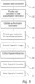
Fig. 5 , flowchart illustrating the exemplary steps of the invention for fingerprint enrollment of a user using thesmart card 204 provided with afingerprint sensor 208. As a first step, a connection for data communication is established, S1, between the fingerprint sensing system of thesmart card 204 and an electronic host device, such as thesmartphone 202. The connection is preferably provided using the above disclosedcommunication apparatus 100, but could alternatively be provided using the wireless connection between e.g. thesmartphone 202 and thesmart card 204, e.g. using NFC, Wi-Fi, etc. - Once the data communication between the electronic devices has been established, the user will be provided, S2, with an instruction to enter e.g. the above mentioned PIN number as a piece of authentication information, within a user interface provided using the
display 206 of thesmartphone 202. The authentication information is validated, S3, typically involving information pre-stored to thesmart card 204. The validation may also involve communication between thesmartphone 202 and a remotely arranged server (not shown), for authenticating the user. If the authentication information, e.g. the PIN, has been successfully validated, the user is further provided, S4, with an instruction to position the finger at thefingerprint sensor 208. The instruction may for example include guidance as how the finger is to be positioned, re-positioned in case of a non-correct positioning, etc. Subsequently, a fingerprint image is acquired, S5, using thefingerprint sensor 208. Theprocessing circuitry 210 provided with thesmart card 204 will then extract, S6, extracting fingerprint features from the fingerprint image and form, S7, a fingerprint template for user authentication based on the extracted fingerprint features. Finally, the fingerprint template is stored, S8, within a digital memory comprised with thesmart card 204. - In a typical implementation of the present invention, the user interface is provided within an app of the
smartphone 202, and the app will also inform once a successful enrollment of the finger has been completed. Thesmart card 204 and/or thecommunication apparatus 100 is subsequently locked from any further use, e.g. for re-enrollment or for us with a different electronic slave device. Also, thesmart card 204 and/or thecommunication apparatus 100 may be locked in case the validation of e.g. the PIN has failed (more than a preselected number of times), or due to other reasons. The app may in some embodiments be a native app provided with the electronic host device, or to be downloaded when needed, for example from thecontrol unit 112, from theprocessing circuitry 210, or from a remote server (such as an "app store"). Downloading of the app to thesmartphone 202 may be automatic, e.g. initiated once the data communication has been established between thesmartphone 202 and thesmart card 204. - The control functionality of the present disclosure may be implemented using existing computer processors, or by a special purpose computer processor for an appropriate system, incorporated for this or another purpose, or by a hardwire system. Embodiments within the scope of the present disclosure include program products comprising machine-readable medium for carrying or having machine-executable instructions or data structures stored thereon. Such machine-readable media can be any available media that can be accessed by a general purpose or special purpose computer or other machine with a processor. By way of example, such machine-readable media can comprise RAM, ROM, EPROM, EEPROM, CD-ROM or other optical disk storage, magnetic disk storage or other magnetic storage devices, or any other medium which can be used to carry or store desired program code in the form of machine-executable instructions or data structures and which can be accessed by a general purpose or special purpose computer or other machine with a processor. When information is transferred or provided over a network or another communications connection (either hardwired, wireless, or a combination of hardwired or wireless) to a machine, the machine properly views the connection as a machine-readable medium. Thus, any such connection is properly termed a machine-readable medium. Combinations of the above are also included within the scope of machine-readable media. Machine-executable instructions include, for example, instructions and data which cause a general purpose computer, special purpose computer, or special purpose processing machines to perform a certain function or group of functions.
- Although the figures may show a sequence the order of the steps may differ from what is depicted. Also two or more steps may be performed concurrently or with partial concurrence. Such variation will depend on the software and hardware systems chosen and on designer choice. All such variations are within the scope of the disclosure. Likewise, software implementations could be accomplished with standard programming techniques with rule based logic and other logic to accomplish the various connection steps, processing steps, comparison steps and decision steps. Additionally, even though the invention has been described with reference to specific exemplifying embodiments thereof, many different alterations, modifications and the like will become apparent for those skilled in the art.
- In addition, variations to the disclosed embodiments can be understood and effected by the skilled addressee in practicing the claimed invention, from a study of the drawings, the disclosure, and the appended claims. Furthermore, in the claims, the word "comprising" does not exclude other elements or steps, and the indefinite article "a" or "an" does not exclude a plurality.
Claims (9)
- A communication apparatus (100) arranged to electrically connect an electronic slave device (204) to an electronic host device (202), the electronic slave device comprising a fingerprint sensor (208) having an array of pixels and configured for capturing a fingerprint representation of a fingerprint pattern of a finger of a user, wherein the communication apparatus comprises:- a cable (102), the cable being a flexible printed circuit,- a connector (104) provided a first end (106) of the cable and arranged to be detachably connected to contact pads comprised with the electronic slave device,- a control unit (112) electrically connected to a second end (114) of the cable, and- a physical interface (116) for allowing the control unit to be electrically connected to the electronic host device,wherein the control unit is:- comprised with the flexible printed circuit,- configured to convert communication signals from the electronic host device to the electronic slave device, the communication signals arranged to control capturing of the fingerprint representation using the fingerprint sensor at the electronic slave device for enrolling the finger of the user, and- configured to lock the communication arrangement if the enrollment is successful, thereby preventing further communication to be performed between the electronic host device and the electronic slave device using the communication apparatus.
- The communication apparatus according to claim 1, wherein the captured fingerprint representation is stored within a memory element comprised with the electronic slave device.
- The communication apparatus according to any one of claims 1 and 2, wherein the connector comprises an adhesive element (110) for securely connecting the connector to the electronic slave device.
- The communication apparatus according to any one of the preceding claims, wherein the electronic slave device is a smart card.
- The communication apparatus according to claim 4, wherein the smart card further comprises processing circuitry (210) connected to and configured to control the operation of the fingerprint sensor.
- The communication apparatus according to claim 4, wherein the smart card further comprises a wireless transceiver electrically connected to and controlled by the processing circuitry.
- The communication apparatus according to any one of the preceding claims, wherein the control unit comprises means for automatically initiating communication between the fingerprint sensor and the electronic host device.
- The communication apparatus according to any one of the preceding claims, wherein the control unit is configured to receive and validate authentication information from the electronic host device, and the electronic slave device is configured to enter into an enrollment process if the authentication information is successfully validated.
- A smart card system, comprising:- an electronic slave device being a smart card comprising contact pads (212), and- a communication apparatus according to any one of claims 1 - 8 detachably connected to the contact pads of the smart card.
Applications Claiming Priority (2)
| Application Number | Priority Date | Filing Date | Title |
|---|---|---|---|
| SE1650864 | 2016-06-20 | ||
| PCT/SE2017/050585 WO2017222445A1 (en) | 2016-06-20 | 2017-06-01 | Communication arrangement to electrically connect a slave to a host device |
Publications (3)
| Publication Number | Publication Date |
|---|---|
| EP3472754A1 EP3472754A1 (en) | 2019-04-24 |
| EP3472754A4 EP3472754A4 (en) | 2020-01-15 |
| EP3472754B1 true EP3472754B1 (en) | 2024-10-02 |
Family
ID=60660941
Family Applications (1)
| Application Number | Title | Priority Date | Filing Date |
|---|---|---|---|
| EP17815805.1A Active EP3472754B1 (en) | 2016-06-20 | 2017-06-01 | Communication arrangement to electrically connect a slave to a host device |
Country Status (4)
| Country | Link |
|---|---|
| US (1) | US10187212B2 (en) |
| EP (1) | EP3472754B1 (en) |
| CN (1) | CN107851190B (en) |
| WO (1) | WO2017222445A1 (en) |
Families Citing this family (8)
| Publication number | Priority date | Publication date | Assignee | Title |
|---|---|---|---|---|
| US10282651B2 (en) | 2017-03-23 | 2019-05-07 | Idex Asa | Sensor array system selectively configurable as a fingerprint sensor or data entry device |
| US11250307B2 (en) | 2017-03-23 | 2022-02-15 | Idex Biometrics Asa | Secure, remote biometric enrollment |
| WO2019116233A1 (en) | 2017-12-12 | 2019-06-20 | Idex Asa | Power source for biometric enrollment with status indicators |
| FR3084182B1 (en) * | 2018-07-18 | 2022-09-16 | Idemia France | METHOD FOR RECORDING BIOMETRIC REFERENCE DATA IN A BIOMETRIC CHIP CARD |
| GB2584434A (en) * | 2019-05-31 | 2020-12-09 | Advanide Holdings Pte Ltd | Enrolment device for a biometric smart card |
| US20210034834A1 (en) | 2019-07-30 | 2021-02-04 | Idex Biometrics Asa | Device With Biometric-Gated Display |
| WO2023249539A1 (en) * | 2022-06-23 | 2023-12-28 | Fingerprint Cards Anacatum Ip Ab | Enrollment assistance device with conductor spiral, biometric system and enrollment method |
| WO2023249540A1 (en) * | 2022-06-23 | 2023-12-28 | Fingerprint Cards Anacatum Ip Ab | Enrollment assistance device with capacitive coupling pads, biometric system and enrollment method |
Family Cites Families (20)
| Publication number | Priority date | Publication date | Assignee | Title |
|---|---|---|---|---|
| US20070220272A1 (en) | 2002-06-25 | 2007-09-20 | Campisi Steven E | Transaction authentication card |
| US7543156B2 (en) * | 2002-06-25 | 2009-06-02 | Resilent, Llc | Transaction authentication card |
| CZ2005209A3 (en) | 2002-09-10 | 2005-12-14 | Ivi Smart Technologies, Inc. | Secure Biometric Identity Verification |
| AU2002951755A0 (en) * | 2002-10-03 | 2002-10-17 | Banque-Tec International Pty Ltd | A smartcard security system for protecting a computer system |
| US8000502B2 (en) | 2005-03-09 | 2011-08-16 | Sandisk Technologies Inc. | Portable memory storage device with biometric identification security |
| US7594603B2 (en) | 2006-03-29 | 2009-09-29 | Stmicroelectronics, Inc. | System and method for sensing biometric and non-biometric smart card devices |
| US20080028230A1 (en) | 2006-05-05 | 2008-01-31 | Tri-D Systems, Inc. | Biometric authentication proximity card |
| US7953670B2 (en) * | 2006-12-27 | 2011-05-31 | Colella Brian A | Biometrically secured identification authentication and card reader device |
| EP2083544B1 (en) * | 2008-01-24 | 2014-05-21 | BlackBerry Limited | Optimized biometric authentication method and system |
| US20090240852A1 (en) | 2008-03-20 | 2009-09-24 | Aten International Co., Ltd. | Uart/usb converting apparatus |
| US8799666B2 (en) * | 2009-10-06 | 2014-08-05 | Synaptics Incorporated | Secure user authentication using biometric information |
| DE102010018860B4 (en) | 2010-04-30 | 2014-10-09 | Few Fahrzeugelektrikwerk Gmbh & Co. Kg | Contacting arrangement for on flat structures, in particular glass panes, existing ladder |
| CN102789587A (en) * | 2011-05-20 | 2012-11-21 | 陶礼安 | Smart card, smart card reader and smart card operation method |
| US20130252456A1 (en) | 2012-03-20 | 2013-09-26 | International Business Machines Corporation | Securing a Field Replaceable Unit |
| US9183365B2 (en) * | 2013-01-04 | 2015-11-10 | Synaptics Incorporated | Methods and systems for fingerprint template enrollment and distribution process |
| US9734386B2 (en) * | 2014-09-12 | 2017-08-15 | Qualcomm Incorporated | Methods, systems and devices for electronic notary with signature and biometric identifier |
| GB201508288D0 (en) | 2015-05-14 | 2015-06-24 | Zwipe As | Self-contained fingerprint identification device |
| US10037528B2 (en) * | 2015-01-14 | 2018-07-31 | Tactilis Sdn Bhd | Biometric device utilizing finger sequence for authentication |
| US10546291B2 (en) * | 2015-09-09 | 2020-01-28 | Samsung Electronics Co., Ltd. | Method and apparatus for performing payment |
| KR20170035294A (en) * | 2015-09-22 | 2017-03-30 | 삼성전자주식회사 | Electronic device and payment method of providing security thereof |
-
2017
- 2017-05-30 US US15/608,050 patent/US10187212B2/en active Active
- 2017-06-01 WO PCT/SE2017/050585 patent/WO2017222445A1/en not_active Ceased
- 2017-06-01 EP EP17815805.1A patent/EP3472754B1/en active Active
- 2017-06-01 CN CN201780002739.8A patent/CN107851190B/en active Active
Also Published As
| Publication number | Publication date |
|---|---|
| CN107851190A (en) | 2018-03-27 |
| WO2017222445A1 (en) | 2017-12-28 |
| CN107851190B (en) | 2019-03-01 |
| US10187212B2 (en) | 2019-01-22 |
| US20170366351A1 (en) | 2017-12-21 |
| EP3472754A1 (en) | 2019-04-24 |
| EP3472754A4 (en) | 2020-01-15 |
Similar Documents
| Publication | Publication Date | Title |
|---|---|---|
| US10187212B2 (en) | Communication arrangement | |
| CN110313008B (en) | Method and smart card suitable for gradual fingerprint registration | |
| TWI553568B (en) | Mobile device and authentication method for mobile payment system | |
| US9699182B2 (en) | Electrocardiogram (ECG) biometric authentication | |
| WO2016054263A1 (en) | Biometric device pairing | |
| EP3559847B1 (en) | Electronic device for biometric authentication of a user | |
| KR20170106998A (en) | Smart card systems including cards and carriers | |
| JP2024513353A (en) | Biometric authentication system with contactless smart card and enrollment support device and method for enrolling users with the system | |
| JP2021523481A (en) | Object verification methods, devices, and systems | |
| KR20220057254A (en) | Electronic device and method for providing mobile identify document in the same | |
| SE1650416A1 (en) | Secure storage of fingerprint related elements | |
| WO2015104001A1 (en) | Data transmission method and system | |
| US11983589B2 (en) | Method for amending a fingerprint template of a smart card | |
| CN110651268B (en) | Methods and electronic devices for authenticating users | |
| JP2020013574A (en) | How to record a reference biometric data item on a biometric smart card | |
| CN107451451B (en) | Unlock control method and related products | |
| KR102320024B1 (en) | Method and apparatus for an authentication based on biological information | |
| EP3752937B1 (en) | Enrollment scheme for an electronic device | |
| US12450462B2 (en) | Method for enabling fingerprint authentication for a smart card | |
| JP2007206941A (en) | Biometric authentication device, biomeric authentication system and biometric data mangement method | |
| JP2024020778A (en) | Electronic devices, card issuing equipment, card systems, authentication information processing methods, and programs | |
| JP2009251885A (en) | Sim holder having voice-authenticating function | |
| CN203204626U (en) | Handheld Devices with Fingerprint Sensing Recognition | |
| HK1192806B (en) | Method and system for transmitting data | |
| HK1192806A (en) | Method and system for transmitting data |
Legal Events
| Date | Code | Title | Description |
|---|---|---|---|
| STAA | Information on the status of an ep patent application or granted ep patent |
Free format text: STATUS: THE INTERNATIONAL PUBLICATION HAS BEEN MADE |
|
| PUAI | Public reference made under article 153(3) epc to a published international application that has entered the european phase |
Free format text: ORIGINAL CODE: 0009012 |
|
| STAA | Information on the status of an ep patent application or granted ep patent |
Free format text: STATUS: REQUEST FOR EXAMINATION WAS MADE |
|
| 17P | Request for examination filed |
Effective date: 20181210 |
|
| AK | Designated contracting states |
Kind code of ref document: A1 Designated state(s): AL AT BE BG CH CY CZ DE DK EE ES FI FR GB GR HR HU IE IS IT LI LT LU LV MC MK MT NL NO PL PT RO RS SE SI SK SM TR |
|
| AX | Request for extension of the european patent |
Extension state: BA ME |
|
| DAV | Request for validation of the european patent (deleted) | ||
| DAX | Request for extension of the european patent (deleted) | ||
| A4 | Supplementary search report drawn up and despatched |
Effective date: 20191213 |
|
| RIC1 | Information provided on ipc code assigned before grant |
Ipc: G06K 19/06 20060101ALI20191209BHEP Ipc: H04L 9/32 20060101ALI20191209BHEP Ipc: G06K 9/00 20060101AFI20191209BHEP Ipc: G06F 13/38 20060101ALI20191209BHEP |
|
| STAA | Information on the status of an ep patent application or granted ep patent |
Free format text: STATUS: EXAMINATION IS IN PROGRESS |
|
| 17Q | First examination report despatched |
Effective date: 20211026 |
|
| RAP1 | Party data changed (applicant data changed or rights of an application transferred) |
Owner name: FINGERPRINT CARDS ANACATUM IP AB |
|
| REG | Reference to a national code |
Ref country code: DE Ref legal event code: R079 Free format text: PREVIOUS MAIN CLASS: G06K0009000000 Ipc: H04L0009320000 Ref country code: DE Ref legal event code: R079 Ref document number: 602017085248 Country of ref document: DE Free format text: PREVIOUS MAIN CLASS: G06K0009000000 Ipc: H04L0009320000 |
|
| GRAP | Despatch of communication of intention to grant a patent |
Free format text: ORIGINAL CODE: EPIDOSNIGR1 |
|
| STAA | Information on the status of an ep patent application or granted ep patent |
Free format text: STATUS: GRANT OF PATENT IS INTENDED |
|
| RIC1 | Information provided on ipc code assigned before grant |
Ipc: H01R 13/66 20060101ALI20240416BHEP Ipc: G06F 21/34 20130101ALI20240416BHEP Ipc: H04L 9/32 20060101AFI20240416BHEP |
|
| INTG | Intention to grant announced |
Effective date: 20240507 |
|
| GRAS | Grant fee paid |
Free format text: ORIGINAL CODE: EPIDOSNIGR3 |
|
| GRAA | (expected) grant |
Free format text: ORIGINAL CODE: 0009210 |
|
| STAA | Information on the status of an ep patent application or granted ep patent |
Free format text: STATUS: THE PATENT HAS BEEN GRANTED |
|
| AK | Designated contracting states |
Kind code of ref document: B1 Designated state(s): AL AT BE BG CH CY CZ DE DK EE ES FI FR GB GR HR HU IE IS IT LI LT LU LV MC MK MT NL NO PL PT RO RS SE SI SK SM TR |
|
| REG | Reference to a national code |
Ref country code: GB Ref legal event code: FG4D |
|
| REG | Reference to a national code |
Ref country code: CH Ref legal event code: EP |
|
| REG | Reference to a national code |
Ref country code: DE Ref legal event code: R096 Ref document number: 602017085248 Country of ref document: DE |
|
| REG | Reference to a national code |
Ref country code: IE Ref legal event code: FG4D |
|
| REG | Reference to a national code |
Ref country code: LT Ref legal event code: MG9D |
|
| REG | Reference to a national code |
Ref country code: NL Ref legal event code: MP Effective date: 20241002 |
|
| REG | Reference to a national code |
Ref country code: AT Ref legal event code: MK05 Ref document number: 1729236 Country of ref document: AT Kind code of ref document: T Effective date: 20241002 |
|
| PG25 | Lapsed in a contracting state [announced via postgrant information from national office to epo] |
Ref country code: NL Free format text: LAPSE BECAUSE OF FAILURE TO SUBMIT A TRANSLATION OF THE DESCRIPTION OR TO PAY THE FEE WITHIN THE PRESCRIBED TIME-LIMIT Effective date: 20241002 |
|
| PG25 | Lapsed in a contracting state [announced via postgrant information from national office to epo] |
Ref country code: NL Free format text: LAPSE BECAUSE OF FAILURE TO SUBMIT A TRANSLATION OF THE DESCRIPTION OR TO PAY THE FEE WITHIN THE PRESCRIBED TIME-LIMIT Effective date: 20241002 |
|
| PG25 | Lapsed in a contracting state [announced via postgrant information from national office to epo] |
Ref country code: IS Free format text: LAPSE BECAUSE OF FAILURE TO SUBMIT A TRANSLATION OF THE DESCRIPTION OR TO PAY THE FEE WITHIN THE PRESCRIBED TIME-LIMIT Effective date: 20250202 Ref country code: PT Free format text: LAPSE BECAUSE OF FAILURE TO SUBMIT A TRANSLATION OF THE DESCRIPTION OR TO PAY THE FEE WITHIN THE PRESCRIBED TIME-LIMIT Effective date: 20250203 Ref country code: HR Free format text: LAPSE BECAUSE OF FAILURE TO SUBMIT A TRANSLATION OF THE DESCRIPTION OR TO PAY THE FEE WITHIN THE PRESCRIBED TIME-LIMIT Effective date: 20241002 |
|
| PG25 | Lapsed in a contracting state [announced via postgrant information from national office to epo] |
Ref country code: FI Free format text: LAPSE BECAUSE OF FAILURE TO SUBMIT A TRANSLATION OF THE DESCRIPTION OR TO PAY THE FEE WITHIN THE PRESCRIBED TIME-LIMIT Effective date: 20241002 |
|
| PG25 | Lapsed in a contracting state [announced via postgrant information from national office to epo] |
Ref country code: BG Free format text: LAPSE BECAUSE OF FAILURE TO SUBMIT A TRANSLATION OF THE DESCRIPTION OR TO PAY THE FEE WITHIN THE PRESCRIBED TIME-LIMIT Effective date: 20241002 |
|
| PG25 | Lapsed in a contracting state [announced via postgrant information from national office to epo] |
Ref country code: ES Free format text: LAPSE BECAUSE OF FAILURE TO SUBMIT A TRANSLATION OF THE DESCRIPTION OR TO PAY THE FEE WITHIN THE PRESCRIBED TIME-LIMIT Effective date: 20241002 |
|
| PG25 | Lapsed in a contracting state [announced via postgrant information from national office to epo] |
Ref country code: NO Free format text: LAPSE BECAUSE OF FAILURE TO SUBMIT A TRANSLATION OF THE DESCRIPTION OR TO PAY THE FEE WITHIN THE PRESCRIBED TIME-LIMIT Effective date: 20250102 |
|
| PG25 | Lapsed in a contracting state [announced via postgrant information from national office to epo] |
Ref country code: AT Free format text: LAPSE BECAUSE OF FAILURE TO SUBMIT A TRANSLATION OF THE DESCRIPTION OR TO PAY THE FEE WITHIN THE PRESCRIBED TIME-LIMIT Effective date: 20241002 Ref country code: LV Free format text: LAPSE BECAUSE OF FAILURE TO SUBMIT A TRANSLATION OF THE DESCRIPTION OR TO PAY THE FEE WITHIN THE PRESCRIBED TIME-LIMIT Effective date: 20241002 Ref country code: GR Free format text: LAPSE BECAUSE OF FAILURE TO SUBMIT A TRANSLATION OF THE DESCRIPTION OR TO PAY THE FEE WITHIN THE PRESCRIBED TIME-LIMIT Effective date: 20250103 |
|
| PG25 | Lapsed in a contracting state [announced via postgrant information from national office to epo] |
Ref country code: PL Free format text: LAPSE BECAUSE OF FAILURE TO SUBMIT A TRANSLATION OF THE DESCRIPTION OR TO PAY THE FEE WITHIN THE PRESCRIBED TIME-LIMIT Effective date: 20241002 Ref country code: CZ Free format text: LAPSE BECAUSE OF FAILURE TO SUBMIT A TRANSLATION OF THE DESCRIPTION OR TO PAY THE FEE WITHIN THE PRESCRIBED TIME-LIMIT Effective date: 20241002 |
|
| PG25 | Lapsed in a contracting state [announced via postgrant information from national office to epo] |
Ref country code: RS Free format text: LAPSE BECAUSE OF FAILURE TO SUBMIT A TRANSLATION OF THE DESCRIPTION OR TO PAY THE FEE WITHIN THE PRESCRIBED TIME-LIMIT Effective date: 20250102 |
|
| PG25 | Lapsed in a contracting state [announced via postgrant information from national office to epo] |
Ref country code: SM Free format text: LAPSE BECAUSE OF FAILURE TO SUBMIT A TRANSLATION OF THE DESCRIPTION OR TO PAY THE FEE WITHIN THE PRESCRIBED TIME-LIMIT Effective date: 20241002 |
|
| REG | Reference to a national code |
Ref country code: DE Ref legal event code: R097 Ref document number: 602017085248 Country of ref document: DE |
|
| PG25 | Lapsed in a contracting state [announced via postgrant information from national office to epo] |
Ref country code: DK Free format text: LAPSE BECAUSE OF FAILURE TO SUBMIT A TRANSLATION OF THE DESCRIPTION OR TO PAY THE FEE WITHIN THE PRESCRIBED TIME-LIMIT Effective date: 20241002 |
|
| PG25 | Lapsed in a contracting state [announced via postgrant information from national office to epo] |
Ref country code: EE Free format text: LAPSE BECAUSE OF FAILURE TO SUBMIT A TRANSLATION OF THE DESCRIPTION OR TO PAY THE FEE WITHIN THE PRESCRIBED TIME-LIMIT Effective date: 20241002 |
|
| PG25 | Lapsed in a contracting state [announced via postgrant information from national office to epo] |
Ref country code: RO Free format text: LAPSE BECAUSE OF FAILURE TO SUBMIT A TRANSLATION OF THE DESCRIPTION OR TO PAY THE FEE WITHIN THE PRESCRIBED TIME-LIMIT Effective date: 20241002 |
|
| PG25 | Lapsed in a contracting state [announced via postgrant information from national office to epo] |
Ref country code: SK Free format text: LAPSE BECAUSE OF FAILURE TO SUBMIT A TRANSLATION OF THE DESCRIPTION OR TO PAY THE FEE WITHIN THE PRESCRIBED TIME-LIMIT Effective date: 20241002 |
|
| PG25 | Lapsed in a contracting state [announced via postgrant information from national office to epo] |
Ref country code: IT Free format text: LAPSE BECAUSE OF FAILURE TO SUBMIT A TRANSLATION OF THE DESCRIPTION OR TO PAY THE FEE WITHIN THE PRESCRIBED TIME-LIMIT Effective date: 20241002 |
|
| PLBE | No opposition filed within time limit |
Free format text: ORIGINAL CODE: 0009261 |
|
| STAA | Information on the status of an ep patent application or granted ep patent |
Free format text: STATUS: NO OPPOSITION FILED WITHIN TIME LIMIT |
|
| PG25 | Lapsed in a contracting state [announced via postgrant information from national office to epo] |
Ref country code: SE Free format text: LAPSE BECAUSE OF FAILURE TO SUBMIT A TRANSLATION OF THE DESCRIPTION OR TO PAY THE FEE WITHIN THE PRESCRIBED TIME-LIMIT Effective date: 20241002 |
|
| 26N | No opposition filed |
Effective date: 20250703 |
|
| REG | Reference to a national code |
Ref country code: DE Ref legal event code: R119 Ref document number: 602017085248 Country of ref document: DE |
|
| REG | Reference to a national code |
Ref country code: CH Ref legal event code: H13 Free format text: ST27 STATUS EVENT CODE: U-0-0-H10-H13 (AS PROVIDED BY THE NATIONAL OFFICE) Effective date: 20260127 |
|
| PG25 | Lapsed in a contracting state [announced via postgrant information from national office to epo] |
Ref country code: MC Free format text: LAPSE BECAUSE OF FAILURE TO SUBMIT A TRANSLATION OF THE DESCRIPTION OR TO PAY THE FEE WITHIN THE PRESCRIBED TIME-LIMIT Effective date: 20241002 |
|
| PG25 | Lapsed in a contracting state [announced via postgrant information from national office to epo] |
Ref country code: LU Free format text: LAPSE BECAUSE OF NON-PAYMENT OF DUE FEES Effective date: 20250601 |
|
| GBPC | Gb: european patent ceased through non-payment of renewal fee |
Effective date: 20250601 |
|
| REG | Reference to a national code |
Ref country code: BE Ref legal event code: MM Effective date: 20250630 |
|
| PG25 | Lapsed in a contracting state [announced via postgrant information from national office to epo] |
Ref country code: GB Free format text: LAPSE BECAUSE OF NON-PAYMENT OF DUE FEES Effective date: 20250601 |
|
| PG25 | Lapsed in a contracting state [announced via postgrant information from national office to epo] |
Ref country code: DE Free format text: LAPSE BECAUSE OF NON-PAYMENT OF DUE FEES Effective date: 20260101 Ref country code: IE Free format text: LAPSE BECAUSE OF NON-PAYMENT OF DUE FEES Effective date: 20250601 |
|
| PG25 | Lapsed in a contracting state [announced via postgrant information from national office to epo] |
Ref country code: BE Free format text: LAPSE BECAUSE OF NON-PAYMENT OF DUE FEES Effective date: 20250630 |
|
| PG25 | Lapsed in a contracting state [announced via postgrant information from national office to epo] |
Ref country code: FR Free format text: LAPSE BECAUSE OF NON-PAYMENT OF DUE FEES Effective date: 20250630 |
|
| PG25 | Lapsed in a contracting state [announced via postgrant information from national office to epo] |
Ref country code: CH Free format text: LAPSE BECAUSE OF NON-PAYMENT OF DUE FEES Effective date: 20250630 |