EP3472440B1 - Internal combustion engine - Google Patents
Internal combustion engine Download PDFInfo
- Publication number
- EP3472440B1 EP3472440B1 EP17813687.5A EP17813687A EP3472440B1 EP 3472440 B1 EP3472440 B1 EP 3472440B1 EP 17813687 A EP17813687 A EP 17813687A EP 3472440 B1 EP3472440 B1 EP 3472440B1
- Authority
- EP
- European Patent Office
- Prior art keywords
- combustion engine
- piston
- cylinder
- chamber
- camshaft
- Prior art date
- Legal status (The legal status is an assumption and is not a legal conclusion. Google has not performed a legal analysis and makes no representation as to the accuracy of the status listed.)
- Active
Links
Images

Classifications
-
- F—MECHANICAL ENGINEERING; LIGHTING; HEATING; WEAPONS; BLASTING
- F01—MACHINES OR ENGINES IN GENERAL; ENGINE PLANTS IN GENERAL; STEAM ENGINES
- F01L—CYCLICALLY OPERATING VALVES FOR MACHINES OR ENGINES
- F01L1/00—Valve-gear or valve arrangements, e.g. lift-valve gear
- F01L1/34—Valve-gear or valve arrangements, e.g. lift-valve gear characterised by the provision of means for changing the timing of the valves without changing the duration of opening and without affecting the magnitude of the valve lift
- F01L1/344—Valve-gear or valve arrangements, e.g. lift-valve gear characterised by the provision of means for changing the timing of the valves without changing the duration of opening and without affecting the magnitude of the valve lift changing the angular relationship between crankshaft and camshaft, e.g. using helicoidal gear
- F01L1/3442—Valve-gear or valve arrangements, e.g. lift-valve gear characterised by the provision of means for changing the timing of the valves without changing the duration of opening and without affecting the magnitude of the valve lift changing the angular relationship between crankshaft and camshaft, e.g. using helicoidal gear using hydraulic chambers with variable volume to transmit the rotating force
-
- F—MECHANICAL ENGINEERING; LIGHTING; HEATING; WEAPONS; BLASTING
- F01—MACHINES OR ENGINES IN GENERAL; ENGINE PLANTS IN GENERAL; STEAM ENGINES
- F01L—CYCLICALLY OPERATING VALVES FOR MACHINES OR ENGINES
- F01L1/00—Valve-gear or valve arrangements, e.g. lift-valve gear
- F01L1/02—Valve drive
- F01L1/04—Valve drive by means of cams, camshafts, cam discs, eccentrics or the like
- F01L1/047—Camshafts
- F01L1/053—Camshafts overhead type
-
- F—MECHANICAL ENGINEERING; LIGHTING; HEATING; WEAPONS; BLASTING
- F02—COMBUSTION ENGINES; HOT-GAS OR COMBUSTION-PRODUCT ENGINE PLANTS
- F02D—CONTROLLING COMBUSTION ENGINES
- F02D13/00—Controlling the engine output power by varying inlet or exhaust valve operating characteristics, e.g. timing
- F02D13/08—Controlling the engine output power by varying inlet or exhaust valve operating characteristics, e.g. timing for rendering engine inoperative or idling
-
- F—MECHANICAL ENGINEERING; LIGHTING; HEATING; WEAPONS; BLASTING
- F02—COMBUSTION ENGINES; HOT-GAS OR COMBUSTION-PRODUCT ENGINE PLANTS
- F02D—CONTROLLING COMBUSTION ENGINES
- F02D17/00—Controlling engines by cutting out individual cylinders; Rendering engines inoperative or idling
- F02D17/04—Controlling engines by cutting out individual cylinders; Rendering engines inoperative or idling rendering engines inoperative or idling, e.g. caused by abnormal conditions
-
- F—MECHANICAL ENGINEERING; LIGHTING; HEATING; WEAPONS; BLASTING
- F15—FLUID-PRESSURE ACTUATORS; HYDRAULICS OR PNEUMATICS IN GENERAL
- F15B—SYSTEMS ACTING BY MEANS OF FLUIDS IN GENERAL; FLUID-PRESSURE ACTUATORS, e.g. SERVOMOTORS; DETAILS OF FLUID-PRESSURE SYSTEMS, NOT OTHERWISE PROVIDED FOR
- F15B1/00—Installations or systems with accumulators; Supply reservoir or sump assemblies
- F15B1/02—Installations or systems with accumulators
- F15B1/04—Accumulators
- F15B1/08—Accumulators using a gas cushion; Gas charging devices; Indicators or floats therefor
- F15B1/24—Accumulators using a gas cushion; Gas charging devices; Indicators or floats therefor with rigid separating means, e.g. pistons
-
- F—MECHANICAL ENGINEERING; LIGHTING; HEATING; WEAPONS; BLASTING
- F01—MACHINES OR ENGINES IN GENERAL; ENGINE PLANTS IN GENERAL; STEAM ENGINES
- F01L—CYCLICALLY OPERATING VALVES FOR MACHINES OR ENGINES
- F01L1/00—Valve-gear or valve arrangements, e.g. lift-valve gear
- F01L1/02—Valve drive
- F01L1/04—Valve drive by means of cams, camshafts, cam discs, eccentrics or the like
- F01L1/047—Camshafts
- F01L1/053—Camshafts overhead type
- F01L2001/0537—Double overhead camshafts [DOHC]
-
- F—MECHANICAL ENGINEERING; LIGHTING; HEATING; WEAPONS; BLASTING
- F01—MACHINES OR ENGINES IN GENERAL; ENGINE PLANTS IN GENERAL; STEAM ENGINES
- F01L—CYCLICALLY OPERATING VALVES FOR MACHINES OR ENGINES
- F01L1/00—Valve-gear or valve arrangements, e.g. lift-valve gear
- F01L1/34—Valve-gear or valve arrangements, e.g. lift-valve gear characterised by the provision of means for changing the timing of the valves without changing the duration of opening and without affecting the magnitude of the valve lift
- F01L1/344—Valve-gear or valve arrangements, e.g. lift-valve gear characterised by the provision of means for changing the timing of the valves without changing the duration of opening and without affecting the magnitude of the valve lift changing the angular relationship between crankshaft and camshaft, e.g. using helicoidal gear
- F01L1/3442—Valve-gear or valve arrangements, e.g. lift-valve gear characterised by the provision of means for changing the timing of the valves without changing the duration of opening and without affecting the magnitude of the valve lift changing the angular relationship between crankshaft and camshaft, e.g. using helicoidal gear using hydraulic chambers with variable volume to transmit the rotating force
- F01L2001/34423—Details relating to the hydraulic feeding circuit
- F01L2001/34426—Oil control valves
- F01L2001/3443—Solenoid driven oil control valves
-
- F—MECHANICAL ENGINEERING; LIGHTING; HEATING; WEAPONS; BLASTING
- F01—MACHINES OR ENGINES IN GENERAL; ENGINE PLANTS IN GENERAL; STEAM ENGINES
- F01L—CYCLICALLY OPERATING VALVES FOR MACHINES OR ENGINES
- F01L1/00—Valve-gear or valve arrangements, e.g. lift-valve gear
- F01L1/34—Valve-gear or valve arrangements, e.g. lift-valve gear characterised by the provision of means for changing the timing of the valves without changing the duration of opening and without affecting the magnitude of the valve lift
- F01L1/344—Valve-gear or valve arrangements, e.g. lift-valve gear characterised by the provision of means for changing the timing of the valves without changing the duration of opening and without affecting the magnitude of the valve lift changing the angular relationship between crankshaft and camshaft, e.g. using helicoidal gear
- F01L1/3442—Valve-gear or valve arrangements, e.g. lift-valve gear characterised by the provision of means for changing the timing of the valves without changing the duration of opening and without affecting the magnitude of the valve lift changing the angular relationship between crankshaft and camshaft, e.g. using helicoidal gear using hydraulic chambers with variable volume to transmit the rotating force
- F01L2001/34423—Details relating to the hydraulic feeding circuit
- F01L2001/34446—Fluid accumulators for the feeding circuit
-
- F—MECHANICAL ENGINEERING; LIGHTING; HEATING; WEAPONS; BLASTING
- F01—MACHINES OR ENGINES IN GENERAL; ENGINE PLANTS IN GENERAL; STEAM ENGINES
- F01L—CYCLICALLY OPERATING VALVES FOR MACHINES OR ENGINES
- F01L1/00—Valve-gear or valve arrangements, e.g. lift-valve gear
- F01L1/34—Valve-gear or valve arrangements, e.g. lift-valve gear characterised by the provision of means for changing the timing of the valves without changing the duration of opening and without affecting the magnitude of the valve lift
- F01L1/344—Valve-gear or valve arrangements, e.g. lift-valve gear characterised by the provision of means for changing the timing of the valves without changing the duration of opening and without affecting the magnitude of the valve lift changing the angular relationship between crankshaft and camshaft, e.g. using helicoidal gear
- F01L2001/34486—Location and number of the means for changing the angular relationship
- F01L2001/34496—Two phasers on different camshafts
-
- F—MECHANICAL ENGINEERING; LIGHTING; HEATING; WEAPONS; BLASTING
- F01—MACHINES OR ENGINES IN GENERAL; ENGINE PLANTS IN GENERAL; STEAM ENGINES
- F01L—CYCLICALLY OPERATING VALVES FOR MACHINES OR ENGINES
- F01L2250/00—Camshaft drives characterised by their transmission means
- F01L2250/02—Camshaft drives characterised by their transmission means the camshaft being driven by chains
-
- F—MECHANICAL ENGINEERING; LIGHTING; HEATING; WEAPONS; BLASTING
- F01—MACHINES OR ENGINES IN GENERAL; ENGINE PLANTS IN GENERAL; STEAM ENGINES
- F01L—CYCLICALLY OPERATING VALVES FOR MACHINES OR ENGINES
- F01L2250/00—Camshaft drives characterised by their transmission means
- F01L2250/04—Camshaft drives characterised by their transmission means the camshaft being driven by belts
Definitions
- the present invention relates to a combustion engine and a vehicle comprising a combustion engine according to the enclosed claims.
- Cam phasers may be used in combustion engines to change the rotational positions of camshafts in relation to each other and in relation to a crankshaft in order to phase-shift, i.e., to push forward or delay the opening and closing times of inlet valves and exhaust valves.
- the engine's performance among others, may be improved, fuel consumption may be reduced, the engine braking performance may be improved and improved control of emissions may be obtained.
- the improved control of emissions may in turn make it possible to eliminate EGR-systems used in exhaust purification.
- US 2010/326383 A1 discloses an apparatus for variably adjusting control times of gas exchange valves in an internal combustion engine.
- the apparatus has a driving element, an output element, at least one pressure chamber, a pressurized medium supply device, and at least one pressure accumulator.
- the supply device allows pressurized medium to be fed to or discharged from the pressure chamber.
- a phase angle of the output element relative to the input element can be changed by feeding or discharging pressurized medium to or from the pressure chamber.
- the pressure accumulator encompasses a movable element that has a first pressure surface which partially delimits a storage space.
- the storage space is or can be connected to the supply device.
- phase-shifting may be achieved with the help of hydraulic cam phasers operated by pressurized oil in the engine oil system.
- a cam phaser may be arranged at each camshaft and supplied with oil with the help of the engine's oil pump to change the rotational positions of the camshafts in relation to each other and in relation to a crankshaft, to phase-shift the opening and closing times of the valves. It is important that the oil pressure in the oil system is sufficiently high for a quick and robust phase-shifting function to be obtained.
- the purpose of such a measure may be to reduce parasitic losses in the engine and to reduce fuel consumption.
- One objective of the present invention is to increase the speed and robustness in a phase-shifting function when hydraulic cam phasers are used.
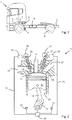
- Fig. 1 shows a motor vehicle 1 with a vehicle frame 2 at which a combustion engine 3 is arranged to operate at least two driving wheels 4.
- An oil pan 5 is arranged at a lower section of the combustion engine 3 and adapted to constitute a collection container for oil after it has circulated through oil channels in the combustion engine's 3 lubricating system 7 to cool and lubricate the engine 3 during operation.
- An oil pump 6 is arranged at the combustion engine 3 to pump oil through the oil channels.
- a pneumatic brake system 8 is arranged at the vehicle frame 2 to brake the wheels of the vehicle.
- the motor vehicle 1 may be a heavy goods vehicle, e.g. a truck or a bus or a lighter vehicle, e.g. a passenger car.
- the combustion engine 3 may be a four-stroke engine and e.g. a diesel engine or an otto engine. In case of alternative embodiments, the combustion engine 3 may be intended for industrial or marine use.
- Fig. 2 shows a combustion engine 3 with at least one cylinder 10, with a piston 11 arranged in each cylinder 10.
- the piston 11 demarcates a combustion chamber 12, which is adapted to be supplied with fuel via a fuel injector 13.
- the piston 11 is connected via a connecting rod 14 to a crankshaft 15, which at rotation moves the piston 11 forwards and backwards in the cylinder 10.
- At least one inlet valve 18 is arranged in each cylinder 10.
- the inlet valve 18 is connected to an inlet system 19 and is adapted to control the supply of air to the combustion chamber 12.
- At least one first camshaft 20 controls the opening and closing times of each inlet valve 18 in relation to the position of the crankshaft 15 and the piston 11.
- At least one exhaust valve 21 is arranged in each cylinder 10.
- the exhaust valve 21 is connected to an exhaust system 22 and is adapted to control the evacuation of exhausts from the combustion chamber 12.
- At least one second camshaft 23 controls the opening and closing times of each inlet valve 21 in relation to the position of the crankshaft 15 and the piston 11.
- at least one camshaft (20, 23) may be used to control the at least one inlet valve (18) and/or the at least one exhaust valve (21).
- two inlet valves 18 and two exhaust valves 21 are arranged in each cylinder 10.
- two first and two second camshafts 20, 23 may be arranged in the combustion engine 3, which is advantageous if the combustion engine 3 is a so-called V-engine.
- the combustion engine 3 has several cylinders 10, e.g. four, six or eight.
- Every camshaft 20, 23 is controlled by and rotatably connected with the crankshaft 15 via a conventional transmission device and is adapted to rotate around a rotational shaft 26, 27 with a speed related to the combustion engine's 3 speed to open and close the respective valve 18, 21.
- At least one hydraulic phase-shifting device 29, a so-called cam phaser is arranged between the crankshaft 15 and at least one of the camshafts 20, 23 to change the rotational position of the at least one camshaft 20, 23 in relation to the crankshaft 15, in order thus to push forward or defer the at least one inlet valve's 18 and/or the at least one exhaust valve's 21 opening and closing times.
- the phase-shifting device 29 may be adapted so that the camshaft 20, 23 may be shifted within an interval in the range of 50-100 crankshaft degrees, but preferably approx. 70 crankshaft degrees, and preferably a phase-shifting device 29 is arranged at each camshaft 20,23.
- a control device 30 is connected to each phase-shifting device 29 via at least one conduit 31, and adapted to control the activation of the phase-shifting device 29 with the help of information regarding one or several parameters related to the operation of the combustion engine 3.
- the control device 30 may be adapted to receive information from sensors 32 and/or from other control devices 33 regarding e.g. the combustion engine's 3 load and engine speed, absolute pressure in the inlet system 19, the temperature of the inlet air, the mass-air flow, exhaust gas temperature, gas control mode and the selected gear in the vehicle's gearbox.
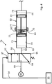
- Fig. 3 shows, in a very simplified manner, a phase-shifting device 29 with a hydraulic control system 36.
- the phase-shifting device 29 may comprise a house 37 into which one end of a camshaft 20, 23 extends.
- the camshaft 20, 23 is fixedly connected with a rotor 38 with a number of radially outward oriented teeth 39, each of which extends into a space 40 in the house 37, demarcating a first chamber 41 and a second chamber 42. All the first chambers 41 are connected to each other via non-displayed channels and all second chambers 42 are connected to each other via channels that are also not displayed.
- a driving wheel 43 e.g.
- a toothed wheel is fixedly connected with the house 37 and mechanically connected to the crankshaft 15 via a transmission device 44, e.g. a cogwheel transmission, a chain transmission or a belt transmission, so that the camshaft 20, 23 and the house 37 rotate with the same speed and preferably half as fast as the crank shaft 15 when the combustion engine 3 is in operation.
- the first chamber 41 is connected to a directional valve 45 via a first hydraulic conduit 47 and the second chamber 42 is connected to the directional valve 45 via a second hydraulic conduit 48.
- the directional valve 45 is connected, via an inlet conduit 51 at which the oil pump 6 is arranged, to the oil pan 5, to which a return conduit 52 from the directional valve 45 also leads.
- a third hydraulic conduit 49 is connected to the inlet conduit 51 between the oil pump 6 and the directional valve 45 to lead oil to the combustion engine's 3 lubricating system 7.
- the directional valve 45 When the directional valve 45 assumes an interim position 54, which may be a resting position, all of its inlet and outlet conduits 47, 48, 51, 52 are blocked. Under the influence of a solenoid 55 that may be controlled by programmed instructions in the control device 30 via a control conduit 31, the directional valve 45 may be made to assume one of the first or a second position 57, 58, in which the inlet conduit 51 is connected to one of the chambers 41, 42, at the same time as the second chamber 41, 42 is connected to the return conduit 52.
- the opening times of the valves 18, 19 may be deferred when the camshaft 20, 23 is turned in the first direction A and pushed forward when the camshaft 20, 23 is turned in the second direction B.
- the actuating speed i.e. the speed with which the respective camshaft 20, 23 may be turned from one position to another may depend on the oil pressure in the lubricating system 7, which oil pressure may be around 1.5 - 4 bar.
- the phase-shifting device 29 may be connected to an accumulator 60, which can be charged by the oil pump 6.
- the accumulator 60 may consist of a cylinder, at whose end wall 67 one end of a fourth hydraulic conduit 68 is connected, whose second end is connected to the inlet conduit 51 in a position after the oil pump 6, between a non-return valve 62 and the directional valve 45, to transport oil from the oil pan 5 to the accumulator 60.
- the non-return valve 62 may be used to ensure that no oil in the accumulator 60 flows back to the oil pan 5 or is supplied to the lubricating system 7 during a phase-shifting process and/or when the oil pressure in the combustion engine is lower than the oil pressure in the accumulator 60.
- a moveable first piston 61 is arranged between two end positions 77, 78, demarcating a first chamber 65 which is connected with the inlet conduit 51 via the fourth hydraulic conduit 68, through which oil may be added to the first chamber 65 and which allows the accumulator 60 to assume a first state at which the first chamber 65 contains oil, and a second state at which at least a part of the oil contained has been supplied to the phase-shifting device 29.
- the first piston 61 is connected to the pressure media controlled cylinder 71, which is adapted to impact the first piston 61 so that it assumes its end positions 77, 78, which end positions 77, 78 correspond to the accumulator's 60 first and second states, respectively.
- the control device 30 is thus adapted to control the activation of the pressure medium controlled cylinder 71 with the help of information regarding one or several parameters relating to the operation of the combustion engine 3.
- the first piston 61 also demarcates a second chamber 66 that may be bled via a non-displayed channel that may extend between the second chamber 66 and the surrounding atmosphere.
- a flange 70 may be arranged, at which the pressure medium controlled cylinder 71 may be fitted.
- the pressure medium controlled cylinder 71 may be a double-acting cylinder and may comprise a second piston 72, movable between two end positions 63, 64, demarcating a first and a second chamber 73, 74 in the cylinder.
- the second piston 72 is connected to a piston rod 75 extending into the accumulator 60 and being directly connected with the first piston 61.
- the first chamber 73 is connected to a directional valve 76 in a control system 79, e.g.
- a pneumatic control system via a first pressure medium conduit 80 and the second chamber 74 is connected to the directional valve 76 via a second pressure medium valve 81.
- the directional valve 76 which may be switched between a first position 88 and a second position 90, is connected to a pressure medium source 85 via an inlet conduit 84 and is connected to the surrounding atmosphere, via an outlet conduit 86.
- the pressure medium source 85 may be a pressurised air source and the pressure medium controlled cylinder 71 may be a pressurised air cylinder that may be connected to the pneumatic brake system 8 in the vehicle ( fig. 1 ) in which the air pressure may be 7-12 bar.
- pressurised air as an operative medium
- other pressure mediums such as oil in vehicle fitted hydraulic systems, which oil has a pressure that is higher than the pressure in the engine's lubricating system.
- One example of such a system is the control system, in whose power steering servo pump the pressure may be 100-170 bar.
- the directional valve 76 When the directional valve 76 assumes the first position 88, which may be a resting position 88, the inlet conduit 84 is connected to the first chamber 73, at the same time as the second chamber 74 is connected to the atmosphere via the outlet conduit 86. Under the influence of a solenoid 89 that may be controlled by programmed instructions in the control device 30 via a control conduit 34, the directional valve 76 may be made to assume a second position 90, in which the inlet conduit 84 is connected to the second chamber 74, at the same time as the first chamber 73 is connected to the atmosphere via the outlet conduit 86.
- the pressure medium controlled cylinder's 71 first chamber 73 is supplied with pressurised medium pressurised medium source 85 via the inlet conduit 84, at the directional valve's 76 first position 88, and the first pressure medium conduit 80 is evacuated, simultaneously with the pressure medium in the pressure medium controlled cylinder's 71 second chamber 74 being evacuated via the second pressure medium conduit 81 and the outlet conduit 86, the pressure medium impacts the pressure medium cylinder's 71 second piston 72 in such a manner that it assumes one end positions 63, which also means that the accumulator's 60 first piston 61 is shifted toward one end position 77, corresponding to the accumulator's 60 first state.
- the first chamber 65 to the right of the accumulator's 60 first piston 61 is filled with oil and is therefore in an oil-filled state.
- a sensor 32 and/or a control device 33 ( fig. 2 ) in the vehicle detects one or several relevant parameters relating to the operation of the combustion engine, they emit a signal to the control device 30, which indicates a phase-shifting activation.
- the control device 30 then emits an out-signal via the conduit 31 to the phase-shifting device's 29 directional valve 45, to assume its first or its second position 57, 58 and an out-signal via the conduit 34 to the directional valve 76, to assume its second position 90.
- the pressure medium from the pressure medium source 85 will now be led to the pressure medium controlled cylinder's 71 second chamber 74, at the same time as its first chamber 73 is bled, which results in the pressure medium impacting the pressure medium cylinder's 71 second piston 72 to assume its second end position 64.
- the second piston 72 thus directly impacts the first piston 61 in the accumulator 60, which first piston is shifted toward its second end position 78 corresponding to the accumulator's 60 second state, wherein substantially all or at last a part of the oil housed in the accumulator's 60 first chamber 65 is led to the directional valve 45 and the phase-shifting device 29, via the fourth hydraulic conduit 68 and the inlet conduit 51, with a pressure corresponding to the pressure in the pressure medium impacting the second piston 72. Since this pressure is substantially higher than the oil pressure that the oil pump 6 may generate, the phase-shifting of the opening and closing times of the valves 18, 21 ( fig. 2 ) will take place significantly faster than if oil was supplied to the phase-shifting device 29 with pressure generated by the oil pump 6.
- the sensor 32 and/or the control device 33 ( fig. 2 ) will no longer emit any signal indicating a phase-shift activation.
- the positional valves 76, 45 will therefore no longer obtain any activation signal from the control device 30 and accordingly will revert to their first position 88 and their interim position 54, respectively, resulting in the second chamber 74 in the pressure medium controlled cylinder 71 being bled, at the same time as the first chamber 73 is supplied with pressure medium impacting the second piston 72 to assume one end position 63, which also means that the first piston 61 of the accumulator 60 is shifted toward one end positions 77, at the same time as the first chamber 65 in the accumulator 60 is supplied with oil from the oil sump 5 with the help of the oil pump 6.
- Fig. 4 shows an alternative embodiment, where the pressure medium controlled cylinder 71 is a single-acting cylinder instead of a double-acting cylinder.
- the pressure medium controlled cylinder's 71 second chamber 74 is connected to a directional valve 92 in the control system 79 via a third pressure medium conduit 82.
- the directional valve 92 which may be switched between a first position 95 and a second position 98, is connected with the pressure medium source 85 via an inlet conduit 93, and connected with the surrounding atmosphere via an outlet conduit 94.
- the first chamber 73 may be bled via a non-displayed channel extending between the first chamber 73 and the surrounding atmosphere.
- a spring element 96 such as a compression spring, is arranged in the first chamber 73. One of the ends of the spring element 96 may be adapted to abut against the second piston's 72 end surface, and its second end may be adapted to abut against an end wall facing the accumulator 60 in the pressure medium controlled cylinder 71.
- the directional valve 92 When the directional valve 92 assumes the first position 95, which may be a resting position, the inlet conduit 93 is blocked at the same time as the outlet conduit 94 is open, wherein the spring element 96 impacts the second piston 72 to assume one end positions 63, which also means that the accumulator's 60 first piston 61 is shifted towards one end positions 77, corresponding to the accumulator's first state. Under the influence of a solenoid 97 that may be controlled by programmed instructions in the control device 30 via a control conduit 34, the directional valve 92 may be made to assume a second position 98, in which the inlet conduit 93 is connected to the second chamber 74.
- the pressure medium from the pressure medium source 85 will now be led to the pressure medium controlled cylinder's 71 second chamber 74, at the same time as its first chamber 73 is bled, which results in the pressure medium impacting the pressure medium cylinder's 71 second piston 72 to compress the spring element 96 and assume its second end position 64.
- the second piston 72 thus directly impacts the first piston 61 in the accumulator 60, which first piston is shifted toward its second end position 78 corresponding to the accumulator's 60 second state, wherein substantially all or at least a part of the oil housed in the accumulator's 60 first chamber 65 is led to the directional valve 45 and the phase-shifting device 29.
- the positional valve 92 will therefore no longer obtain any activation signal from the control device 30 and accordingly will revert to its first position 95, resulting in the second chamber 74 in the pressure medium controlled cylinder 71 being bled, at the same time as the second piston 72 is pressed against one end positions 63 with the help of the spring element 96, which also means that the first piston 61 in the accumulator 60 is shifted towards one end position 77, at the same time as the first chamber 65 in the accumulator 60 is supplied with oil from the oil sump 5 with the help of the oil pump 6.
- directional valves 45, 76, 92 are used, which may be set into various states, one of which states 54, 88, 95 is described as a resting state. In alternative embodiments, and depending on the current application, any state may be selected as the resting state.
- the description shows a directional valve 45 controlled electrically in two directions and directional valves 76, 92 controlled electrically in one direction and with a return spring in another direction.
- the directional valve 45 may be controlled electrically in one direction and with a return spring in one direction, and likewise the valves 76, 92 maybe controlled electrically in two directions.
Landscapes
- Engineering & Computer Science (AREA)
- Mechanical Engineering (AREA)
- General Engineering & Computer Science (AREA)
- Physics & Mathematics (AREA)
- Fluid Mechanics (AREA)
- Chemical & Material Sciences (AREA)
- Combustion & Propulsion (AREA)
- Valve Device For Special Equipments (AREA)
Description
- The present invention relates to a combustion engine and a vehicle comprising a combustion engine according to the enclosed claims.
- Cam phasers may be used in combustion engines to change the rotational positions of camshafts in relation to each other and in relation to a crankshaft in order to phase-shift, i.e., to push forward or delay the opening and closing times of inlet valves and exhaust valves. By using cam phasers, the engine's performance, among others, may be improved, fuel consumption may be reduced, the engine braking performance may be improved and improved control of emissions may be obtained. The improved control of emissions may in turn make it possible to eliminate EGR-systems used in exhaust purification.
-
US 2010/326383 A1 discloses an apparatus for variably adjusting control times of gas exchange valves in an internal combustion engine. The apparatus has a driving element, an output element, at least one pressure chamber, a pressurized medium supply device, and at least one pressure accumulator. The supply device allows pressurized medium to be fed to or discharged from the pressure chamber. A phase angle of the output element relative to the input element can be changed by feeding or discharging pressurized medium to or from the pressure chamber. The pressure accumulator encompasses a movable element that has a first pressure surface which partially delimits a storage space. The storage space is or can be connected to the supply device. -
US 8,714,123 B2 shows that phase-shifting may be achieved with the help of hydraulic cam phasers operated by pressurized oil in the engine oil system. A cam phaser may be arranged at each camshaft and supplied with oil with the help of the engine's oil pump to change the rotational positions of the camshafts in relation to each other and in relation to a crankshaft, to phase-shift the opening and closing times of the valves. It is important that the oil pressure in the oil system is sufficiently high for a quick and robust phase-shifting function to be obtained. To ensure a higher oil pressure than otherwise, it is prior art to, when the engine is in operation, add oil to an accumulator tank in which the oil pressure may be increased with the help of a spring-loaded piston or similar, and to add the pressurised oil to a cam phaser during a phase-shifting process, at least on the occasions where the oil pressure achieved by the oil pump is not sufficiently high. - It may be desirable to decrease the oil pressure in the engine to be able to use a smaller oil pump than otherwise. The purpose of such a measure may be to reduce parasitic losses in the engine and to reduce fuel consumption. In some operating modes, e.g. when a vehicle is driven with a low engine speed or at a transition from idling to operation with a higher engine load, there may be a risk that the oil pressure is too low for a quick and robust phase-shifting function to be obtained, even though the pressurised oil in the accumulator tank is used.
- One objective of the present invention is to increase the speed and robustness in a phase-shifting function when hydraulic cam phasers are used. These and other purposes are achieved through the features described in the claims below.
- Through the use of the invention, a very fast and robust regulation of the cam phaser is achieved, with a high pressure providing very good restraining load against variable camshaft speeds. Since the pressure is very high, the oil pressure in the engine may be reduced and a smaller oil pump than otherwise may be used, reducing parasitic losses in the engine and thus also fuel consumption.
- Other features and advantages of the invention are set out in the claims, the description of the example embodiment and the enclosed drawings.
- Below is a description, by way of example, of preferred embodiments of the invention with reference to the enclosed drawings, in which:
-
Fig. 1 shows a vehicle with a combustion engine according to the present invention. -
Fig. 2 is a cross-sectional view of a schematically displayed combustion engine according to the present invention. -
Fig. 3 shows a schematic display of a hydraulic cam phaser and a control system for the same, according to a first embodiment of the present invention. -
Fig. 4 shows a schematic display of a hydraulic cam phaser and a control system for the same, according to a second embodiment of the present invention. -
Fig. 1 shows a motor vehicle 1 with avehicle frame 2 at which acombustion engine 3 is arranged to operate at least twodriving wheels 4. Anoil pan 5 is arranged at a lower section of thecombustion engine 3 and adapted to constitute a collection container for oil after it has circulated through oil channels in the combustion engine's 3 lubricatingsystem 7 to cool and lubricate theengine 3 during operation. Anoil pump 6 is arranged at thecombustion engine 3 to pump oil through the oil channels. Apneumatic brake system 8 is arranged at thevehicle frame 2 to brake the wheels of the vehicle. The motor vehicle 1 may be a heavy goods vehicle, e.g. a truck or a bus or a lighter vehicle, e.g. a passenger car. Thecombustion engine 3 may be a four-stroke engine and e.g. a diesel engine or an otto engine. In case of alternative embodiments, thecombustion engine 3 may be intended for industrial or marine use. -
Fig. 2 shows acombustion engine 3 with at least onecylinder 10, with apiston 11 arranged in eachcylinder 10. Thepiston 11 demarcates acombustion chamber 12, which is adapted to be supplied with fuel via afuel injector 13. Thepiston 11 is connected via a connectingrod 14 to acrankshaft 15, which at rotation moves thepiston 11 forwards and backwards in thecylinder 10. At least oneinlet valve 18 is arranged in eachcylinder 10. Theinlet valve 18 is connected to aninlet system 19 and is adapted to control the supply of air to thecombustion chamber 12. At least onefirst camshaft 20 controls the opening and closing times of eachinlet valve 18 in relation to the position of thecrankshaft 15 and thepiston 11. At least oneexhaust valve 21 is arranged in eachcylinder 10. Theexhaust valve 21 is connected to anexhaust system 22 and is adapted to control the evacuation of exhausts from thecombustion chamber 12. At least onesecond camshaft 23 controls the opening and closing times of eachinlet valve 21 in relation to the position of thecrankshaft 15 and thepiston 11. In an alternative embodiment, at least one camshaft (20, 23) may be used to control the at least one inlet valve (18) and/or the at least one exhaust valve (21). Preferably, twoinlet valves 18 and twoexhaust valves 21 are arranged in eachcylinder 10. Depending on the type ofcombustion engine 3, two first and twosecond camshafts combustion engine 3, which is advantageous if thecombustion engine 3 is a so-called V-engine. Preferably, thecombustion engine 3 hasseveral cylinders 10, e.g. four, six or eight. - Every
camshaft crankshaft 15 via a conventional transmission device and is adapted to rotate around arotational shaft respective valve device 29, a so-called cam phaser, is arranged between thecrankshaft 15 and at least one of thecamshafts camshaft crankshaft 15, in order thus to push forward or defer the at least one inlet valve's 18 and/or the at least one exhaust valve's 21 opening and closing times. The phase-shiftingdevice 29 may be adapted so that thecamshaft device 29 is arranged at eachcamshaft - A
control device 30 is connected to each phase-shifting device 29 via at least oneconduit 31, and adapted to control the activation of the phase-shiftingdevice 29 with the help of information regarding one or several parameters related to the operation of thecombustion engine 3. Thecontrol device 30 may be adapted to receive information fromsensors 32 and/or fromother control devices 33 regarding e.g. the combustion engine's 3 load and engine speed, absolute pressure in theinlet system 19, the temperature of the inlet air, the mass-air flow, exhaust gas temperature, gas control mode and the selected gear in the vehicle's gearbox. -
Fig. 3 shows, in a very simplified manner, a phase-shiftingdevice 29 with ahydraulic control system 36. The phase-shiftingdevice 29 may comprise ahouse 37 into which one end of acamshaft camshaft rotor 38 with a number of radially outwardoriented teeth 39, each of which extends into aspace 40 in thehouse 37, demarcating afirst chamber 41 and asecond chamber 42. All thefirst chambers 41 are connected to each other via non-displayed channels and allsecond chambers 42 are connected to each other via channels that are also not displayed. Adriving wheel 43, e.g. a toothed wheel, is fixedly connected with thehouse 37 and mechanically connected to thecrankshaft 15 via atransmission device 44, e.g. a cogwheel transmission, a chain transmission or a belt transmission, so that thecamshaft house 37 rotate with the same speed and preferably half as fast as thecrank shaft 15 when thecombustion engine 3 is in operation. Thefirst chamber 41 is connected to adirectional valve 45 via a firsthydraulic conduit 47 and thesecond chamber 42 is connected to thedirectional valve 45 via a secondhydraulic conduit 48. Thedirectional valve 45 is connected, via aninlet conduit 51 at which theoil pump 6 is arranged, to theoil pan 5, to which areturn conduit 52 from thedirectional valve 45 also leads. A thirdhydraulic conduit 49 is connected to theinlet conduit 51 between theoil pump 6 and thedirectional valve 45 to lead oil to the combustion engine's 3lubricating system 7. - When the
directional valve 45 assumes aninterim position 54, which may be a resting position, all of its inlet andoutlet conduits solenoid 55 that may be controlled by programmed instructions in thecontrol device 30 via acontrol conduit 31, thedirectional valve 45 may be made to assume one of the first or asecond position inlet conduit 51 is connected to one of thechambers second chamber return conduit 52. When thefirst chamber 41 at thefirst position 57 of the directional valve is supplied with oil with the help of theoil pump 6, at the same time as oil in thesecond chamber 42 is returned to theoil pan 5 via thereturn conduit 52, thecamshaft house 37, pushing forward the opening and closing times of thevalves second chamber 42 at thesecond position 58 of the directional valve is supplied with oil with the help of theoil pump 6, at the same time as oil in thefirst chamber 41 is returned to theoil pan 5 via thereturn conduit 52, thecamshaft house 37, deferring the opening and closing times of thevalves valves camshaft camshaft respective camshaft lubricating system 7, which oil pressure may be around 1.5 - 4 bar. To obtain a higher actuating speed, even if the pressure in thelubricating system 7 is relatively low, the phase-shiftingdevice 29 may be connected to anaccumulator 60, which can be charged by theoil pump 6. and in which the oil pressure may be increased with the help of a pressure media controlled cylinder 71 before or during the phase-shifting process. Theaccumulator 60 may consist of a cylinder, at whoseend wall 67 one end of a fourthhydraulic conduit 68 is connected, whose second end is connected to theinlet conduit 51 in a position after theoil pump 6, between anon-return valve 62 and thedirectional valve 45, to transport oil from theoil pan 5 to theaccumulator 60. Thenon-return valve 62 may be used to ensure that no oil in theaccumulator 60 flows back to theoil pan 5 or is supplied to thelubricating system 7 during a phase-shifting process and/or when the oil pressure in the combustion engine is lower than the oil pressure in theaccumulator 60. - In the
accumulator 60, a moveablefirst piston 61 is arranged between twoend positions first chamber 65 which is connected with theinlet conduit 51 via the fourthhydraulic conduit 68, through which oil may be added to thefirst chamber 65 and which allows theaccumulator 60 to assume a first state at which thefirst chamber 65 contains oil, and a second state at which at least a part of the oil contained has been supplied to the phase-shiftingdevice 29. Thefirst piston 61 is connected to the pressure media controlled cylinder 71, which is adapted to impact thefirst piston 61 so that it assumes itsend positions control device 30 is thus adapted to control the activation of the pressure medium controlled cylinder 71 with the help of information regarding one or several parameters relating to the operation of thecombustion engine 3. Thefirst piston 61 also demarcates asecond chamber 66 that may be bled via a non-displayed channel that may extend between thesecond chamber 66 and the surrounding atmosphere. - At the accumulator's 60
second end wall 69, a flange 70 may be arranged, at which the pressure medium controlled cylinder 71 may be fitted. The pressure medium controlled cylinder 71 may be a double-acting cylinder and may comprise asecond piston 72, movable between twoend positions second chamber second piston 72 is connected to apiston rod 75 extending into theaccumulator 60 and being directly connected with thefirst piston 61. Thefirst chamber 73 is connected to adirectional valve 76 in acontrol system 79, e.g. a pneumatic control system, via a firstpressure medium conduit 80 and thesecond chamber 74 is connected to thedirectional valve 76 via a second pressuremedium valve 81. Thedirectional valve 76, which may be switched between a first position 88 and asecond position 90, is connected to a pressuremedium source 85 via an inlet conduit 84 and is connected to the surrounding atmosphere, via anoutlet conduit 86. The pressuremedium source 85 may be a pressurised air source and the pressure medium controlled cylinder 71 may be a pressurised air cylinder that may be connected to thepneumatic brake system 8 in the vehicle (fig. 1 ) in which the air pressure may be 7-12 bar. Instead of using pressurised air as an operative medium, other pressure mediums may obviously be used, such as oil in vehicle fitted hydraulic systems, which oil has a pressure that is higher than the pressure in the engine's lubricating system. One example of such a system is the control system, in whose power steering servo pump the pressure may be 100-170 bar. - When the
directional valve 76 assumes the first position 88, which may be a resting position 88, the inlet conduit 84 is connected to thefirst chamber 73, at the same time as thesecond chamber 74 is connected to the atmosphere via theoutlet conduit 86. Under the influence of asolenoid 89 that may be controlled by programmed instructions in thecontrol device 30 via acontrol conduit 34, thedirectional valve 76 may be made to assume asecond position 90, in which the inlet conduit 84 is connected to thesecond chamber 74, at the same time as thefirst chamber 73 is connected to the atmosphere via theoutlet conduit 86. When the pressure medium controlled cylinder's 71first chamber 73 is supplied with pressurised medium pressurisedmedium source 85 via the inlet conduit 84, at the directional valve's 76 first position 88, and the firstpressure medium conduit 80 is evacuated, simultaneously with the pressure medium in the pressure medium controlled cylinder's 71second chamber 74 being evacuated via the secondpressure medium conduit 81 and theoutlet conduit 86, the pressure medium impacts the pressure medium cylinder's 71second piston 72 in such a manner that it assumes one end positions 63, which also means that the accumulator's 60first piston 61 is shifted toward oneend position 77, corresponding to the accumulator's 60 first state. Thefirst chamber 65 to the right of the accumulator's 60first piston 61 is filled with oil and is therefore in an oil-filled state. When asensor 32 and/or a control device 33 (fig. 2 ) in the vehicle detects one or several relevant parameters relating to the operation of the combustion engine, they emit a signal to thecontrol device 30, which indicates a phase-shifting activation. Thecontrol device 30 then emits an out-signal via theconduit 31 to the phase-shifting device's 29directional valve 45, to assume its first or itssecond position conduit 34 to thedirectional valve 76, to assume itssecond position 90. The pressure medium from the pressuremedium source 85 will now be led to the pressure medium controlled cylinder's 71second chamber 74, at the same time as itsfirst chamber 73 is bled, which results in the pressure medium impacting the pressure medium cylinder's 71second piston 72 to assume itssecond end position 64. Thesecond piston 72 thus directly impacts thefirst piston 61 in theaccumulator 60, which first piston is shifted toward itssecond end position 78 corresponding to the accumulator's 60 second state, wherein substantially all or at last a part of the oil housed in the accumulator's 60first chamber 65 is led to thedirectional valve 45 and the phase-shiftingdevice 29, via the fourthhydraulic conduit 68 and theinlet conduit 51, with a pressure corresponding to the pressure in the pressure medium impacting thesecond piston 72. Since this pressure is substantially higher than the oil pressure that theoil pump 6 may generate, the phase-shifting of the opening and closing times of thevalves 18, 21 (fig. 2 ) will take place significantly faster than if oil was supplied to the phase-shiftingdevice 29 with pressure generated by theoil pump 6. After the phase-shifting has been carried out, thesensor 32 and/or the control device 33 (fig. 2 ) will no longer emit any signal indicating a phase-shift activation. Thepositional valves control device 30 and accordingly will revert to their first position 88 and theirinterim position 54, respectively, resulting in thesecond chamber 74 in the pressure medium controlled cylinder 71 being bled, at the same time as thefirst chamber 73 is supplied with pressure medium impacting thesecond piston 72 to assume oneend position 63, which also means that thefirst piston 61 of theaccumulator 60 is shifted toward one end positions 77, at the same time as thefirst chamber 65 in theaccumulator 60 is supplied with oil from theoil sump 5 with the help of theoil pump 6. -
Fig. 4 shows an alternative embodiment, where the pressure medium controlled cylinder 71 is a single-acting cylinder instead of a double-acting cylinder. The pressure medium controlled cylinder's 71second chamber 74 is connected to adirectional valve 92 in thecontrol system 79 via a third pressuremedium conduit 82. Thedirectional valve 92, which may be switched between afirst position 95 and asecond position 98, is connected with the pressuremedium source 85 via aninlet conduit 93, and connected with the surrounding atmosphere via anoutlet conduit 94. Thefirst chamber 73 may be bled via a non-displayed channel extending between thefirst chamber 73 and the surrounding atmosphere. Aspring element 96, such as a compression spring, is arranged in thefirst chamber 73. One of the ends of thespring element 96 may be adapted to abut against the second piston's 72 end surface, and its second end may be adapted to abut against an end wall facing theaccumulator 60 in the pressure medium controlled cylinder 71. - When the
directional valve 92 assumes thefirst position 95, which may be a resting position, theinlet conduit 93 is blocked at the same time as theoutlet conduit 94 is open, wherein thespring element 96 impacts thesecond piston 72 to assume one end positions 63, which also means that the accumulator's 60first piston 61 is shifted towards one end positions 77, corresponding to the accumulator's first state. Under the influence of asolenoid 97 that may be controlled by programmed instructions in thecontrol device 30 via acontrol conduit 34, thedirectional valve 92 may be made to assume asecond position 98, in which theinlet conduit 93 is connected to thesecond chamber 74. The pressure medium from the pressuremedium source 85 will now be led to the pressure medium controlled cylinder's 71second chamber 74, at the same time as itsfirst chamber 73 is bled, which results in the pressure medium impacting the pressure medium cylinder's 71second piston 72 to compress thespring element 96 and assume itssecond end position 64. Thesecond piston 72 thus directly impacts thefirst piston 61 in theaccumulator 60, which first piston is shifted toward itssecond end position 78 corresponding to the accumulator's 60 second state, wherein substantially all or at least a part of the oil housed in the accumulator's 60first chamber 65 is led to thedirectional valve 45 and the phase-shiftingdevice 29. Once the phase-shift has been completed, thepositional valve 92 will therefore no longer obtain any activation signal from thecontrol device 30 and accordingly will revert to itsfirst position 95, resulting in thesecond chamber 74 in the pressure medium controlled cylinder 71 being bled, at the same time as thesecond piston 72 is pressed against one end positions 63 with the help of thespring element 96, which also means that thefirst piston 61 in theaccumulator 60 is shifted towards oneend position 77, at the same time as thefirst chamber 65 in theaccumulator 60 is supplied with oil from theoil sump 5 with the help of theoil pump 6. - In the described embodiments,
directional valves directional valve 45 controlled electrically in two directions anddirectional valves directional valve 45 may be controlled electrically in one direction and with a return spring in one direction, and likewise thevalves
Claims (12)
- Combustion engine comprising- at least one cylinder (10)- at least one inlet valve (18) arranged in each cylinder (10)- at least one exhaust valve (21) arranged in each cylinder (10)- at least one camshaft (20, 23) controlling the at least one inlet valve (18) and/or the at least one exhaust valve (21)- one crankshaft (15) controlling the at least one camshaft (20, 23)- at least one hydraulic phase-shifting device (29) arranged between the crankshaft (15) and the at least one camshaft (20, 23) to change its rotational position in relation to the crankshaft (15) to push forward or defer the at least one inlet valve's (18) and/or the at least one exhaust valve's (21) opening and closing times, which phase-shifting device (29) is connected to an accumulator (60), in which a first piston (61), moveable between two end positions (77, 78) demarcates a first chamber (65) connected to an inlet conduit (51) through which oil may be supplied to the first chamber (65) and which allows the accumulator (60) to assume a first state at which the first chamber (65) contains oil, and a second state at which at least a part of the contained oil has been supplied to the phase-shifting device 29, wherein the first piston (61) is connected with a pressure-medium controlled cylinder (71) adapted to impact the first piston (61) to assume its end positions (77, 78), which end positions (77,78) correspond to the accumulator's (60) first and second state, respectively, characterised in that the pressure-medium controlled cylinder (71) comprises a second piston (72), moveable between two end positions (63,64) demarcating a first and a second chamber (73,74) in the cylinder and that the second piston (72) is connected to a piston rod (75) extending into the accumulator (60) and which is connected to the first piston (61), and wherein the second chamber (74) is connected with a directional valve (92) via a third pressure-medium conduit (82), that the first chamber (73) contains at least one spring element (96) and that the directional valve (92) is connected with a pressure medium source (85) via an inlet conduit (93), wherein the directional valve (92) may be switched between a second position (98) to supply pressure-medium to the second space (74) and shift the first piston (61) towards its second end position (78), corresponding to a second state, and a first position (95) where the spring element (96) is adapted to shift the first piston (61) towards one end positions (77), corresponding to the first state.
- Combustion engine according to claim 1, characterised in that a control unit (30) is adapted to control the activation of the pressure medium controlled cylinder (71) with the help of information regarding one or more parameters related to the operation of the combustion engine (3).
- Combustion engine according to any of the previous claims, characterised in that the pressure medium controlled cylinder (71) is a pneumatic cylinder.
- Combustion engine according to claim 3, characterised in that the pneumatic cylinder is connected to a pneumatic brake system (8).
- Combustion engine according to any of the previous claims, characterised in that two inlet valves (18) and two exhaust valves (21) are arranged in each cylinder (10).
- Combustion engine according to any of the previous claims, characterised in that the combustion engine comprises at least one first camshaft (20) controlling each inlet valve (18) and at least one second camshaft (23) controlling each exhaust valve (21).
- Combustion engine according to any of the previous claims, characterised in that two first and two second camshafts (20, 23) are arranged in the combustion engine (3).
- Combustion engine according to any of the previous claims, characterised in that a phase-shifting device (29) is arranged for each camshaft (20, 23).
- Combustion engine according to any of the previous claims, characterised in that the combustion engine (3) is a diesel engine.
- Combustion engine according to any of the previous claims, characterised in that the phase-shifting device (29) is adapted so that the camshaft (20, 23) is shiftable within an interval in the order of 60-100 crankshaft degrees.
- Combustion engine according to any of claims 1-9, characterised in that a phase-shifting device (29) is adapted so that the camshaft (20, 23) is shiftable 70 crankshaft degrees.
- Vehicle, characterised in that it comprises a combustion engine according to any of claims 1-11.
Applications Claiming Priority (2)
| Application Number | Priority Date | Filing Date | Title |
|---|---|---|---|
| SE1650834A SE540733C2 (en) | 2016-06-15 | 2016-06-15 | Internal combustion engine and vehicle comprising a hydraulic phase displacement device |
| PCT/SE2017/050586 WO2017217908A1 (en) | 2016-06-15 | 2017-06-01 | Internal combustion engine |
Publications (3)
| Publication Number | Publication Date |
|---|---|
| EP3472440A1 EP3472440A1 (en) | 2019-04-24 |
| EP3472440A4 EP3472440A4 (en) | 2019-12-18 |
| EP3472440B1 true EP3472440B1 (en) | 2021-02-24 |
Family
ID=60663562
Family Applications (1)
| Application Number | Title | Priority Date | Filing Date |
|---|---|---|---|
| EP17813687.5A Active EP3472440B1 (en) | 2016-06-15 | 2017-06-01 | Internal combustion engine |
Country Status (7)
| Country | Link |
|---|---|
| US (1) | US10927720B2 (en) |
| EP (1) | EP3472440B1 (en) |
| KR (1) | KR20190010664A (en) |
| CN (1) | CN109312640B (en) |
| BR (1) | BR112018076086A2 (en) |
| SE (1) | SE540733C2 (en) |
| WO (1) | WO2017217908A1 (en) |
Families Citing this family (9)
| Publication number | Priority date | Publication date | Assignee | Title |
|---|---|---|---|---|
| DE102018109027B4 (en) | 2018-04-17 | 2024-04-25 | Schaeffler Technologies AG & Co. KG | Adjustment device for a camshaft adjuster |
| SE1851502A1 (en) | 2018-12-04 | 2020-06-05 | Scania Cv Ab | Vehicle and Method for Operating Powertrain of a Vehicle |
| SE542977C2 (en) | 2019-02-20 | 2020-09-22 | Scania Cv Ab | Four-Stroke Internal Combustion Engine and Method of Operating Four-Stroke Internal Combustion Engine |
| SE1951201A1 (en) | 2019-10-23 | 2021-02-23 | Scania Cv Ab | Four-Stroke Internal Combustion Engine and Method of Controlling Timings of an Exhaust Camshaft and an Intake Camshaft |
| SE544230C2 (en) | 2020-03-26 | 2022-03-08 | Scania Cv Ab | Method and arrangement for variable valve timing for inernal combustion engine; vehicle and engine with such arrangement; computer program and computer readable medium for such a method |
| US11644101B2 (en) * | 2020-06-04 | 2023-05-09 | Alton Reich | Seal inflation/deflation apparatus and method of use thereof |
| SE544581C2 (en) | 2020-06-24 | 2022-07-26 | Scania Cv Ab | Vibration Reduction in Internal Combustion Engine |
| SE544784C2 (en) | 2020-10-09 | 2022-11-15 | Scania Cv Ab | Variable Valve Timing Internal Combustion Engine |
| SE545437C2 (en) | 2020-12-11 | 2023-09-12 | Scania Cv Ab | Controlling Valve Actuation of an Internal Combustion Engine |
Family Cites Families (21)
| Publication number | Priority date | Publication date | Assignee | Title |
|---|---|---|---|---|
| DE3616234A1 (en) * | 1986-05-14 | 1987-11-19 | Bayerische Motoren Werke Ag | DEVICE FOR THE RELATIVE TURNING CHANGE OF TWO DRIVELY CONNECTED SHAFTS, ESPECIALLY BETWEEN A CRANKSHAFT AND CAMSHAFT BEARING IN A MACHINE HOUSING OF AN INTERNAL COMBUSTION ENGINE |
| DE3930157A1 (en) | 1989-09-09 | 1991-03-21 | Bosch Gmbh Robert | DEVICE FOR ADJUSTING THE TURNING ANGLE ASSIGNMENT OF A CAMSHAFT TO YOUR DRIVE ELEMENT |
| JP3786511B2 (en) * | 1997-11-20 | 2006-06-14 | 株式会社日本自動車部品総合研究所 | Oil quantity control device in lubricating oil circuit of internal combustion engine |
| US6234125B1 (en) * | 1998-03-30 | 2001-05-22 | Aft Atlas Fahrzeugtechnik Gmbh | Apparatus for angular adjustment of camshafts relative to crankshafts in combustion engines |
| DE10024268B4 (en) * | 2000-05-17 | 2012-11-29 | Robert Bosch Gmbh | Device for gasoline direct injection in a reciprocating internal combustion engine |
| US6925976B2 (en) * | 2003-03-06 | 2005-08-09 | Jenara Enterprises Ltd. | Modal variable valve actuation system for internal combustion engine and method for operating the same |
| DE10352255B4 (en) | 2003-11-08 | 2017-03-09 | Schaeffler Technologies AG & Co. KG | Adjustment device for adjusting the relative angular position of a camshaft relative to a crankshaft of an internal combustion engine |
| DE102004033522A1 (en) | 2004-07-10 | 2006-02-09 | Ina-Schaeffler Kg | Camshaft adjuster with electric drive |
| US7258100B2 (en) * | 2004-08-03 | 2007-08-21 | Bruce Pinkston | Internal combustion engine control |
| WO2006127347A1 (en) | 2005-05-23 | 2006-11-30 | Borgwarner Inc | Integrated check valve |
| US7536984B2 (en) | 2007-04-16 | 2009-05-26 | Lgd Technology, Llc | Variable valve actuator with a pneumatic booster |
| DE102007056685A1 (en) * | 2007-11-24 | 2009-05-28 | Schaeffler Kg | Device for the variable adjustment of the timing of gas exchange valves of an internal combustion engine |
| DE102007056684B4 (en) * | 2007-11-24 | 2016-02-18 | Schaeffler Technologies AG & Co. KG | accumulator |
| DE102008001802A1 (en) * | 2008-05-15 | 2009-11-19 | Robert Bosch Gmbh | Cam shaft rotation angle position changing device, has pressure reservoir e.g. spring-tensioned piston reservoir, which is flow connected with oil supply line downstream to check valve and upstream to control valve by connecting pipe |
| JP2011236781A (en) * | 2010-05-07 | 2011-11-24 | Aisin Seiki Co Ltd | Device for control of valve timing |
| JP5654940B2 (en) * | 2011-04-21 | 2015-01-14 | 日立オートモティブシステムズ株式会社 | Variable valve operating controller and internal combustion engine variable valve operating device |
| US8714123B2 (en) | 2012-01-18 | 2014-05-06 | Ford Global Technologies, Llc | Oil pressure modification for variable cam timing |
| DE102012009668B3 (en) * | 2012-05-03 | 2013-08-14 | Hydac Technology Gmbh | Device for saving energy in hydraulically operated equipment |
| DE102013207616B4 (en) | 2013-04-26 | 2022-03-24 | Schaeffler Technologies AG & Co. KG | Camshaft adjustment device with central locking device |
| US9200547B2 (en) | 2013-10-08 | 2015-12-01 | GM Global Technology Operations LLC | Efficient phaser actuation supply system |
| US9611764B2 (en) * | 2014-10-21 | 2017-04-04 | Ford Global Technologies, Llc | Method and system for variable cam timing device |
-
2016
- 2016-06-15 SE SE1650834A patent/SE540733C2/en unknown
-
2017
- 2017-06-01 KR KR1020187037851A patent/KR20190010664A/en not_active Ceased
- 2017-06-01 WO PCT/SE2017/050586 patent/WO2017217908A1/en not_active Ceased
- 2017-06-01 US US16/307,901 patent/US10927720B2/en active Active
- 2017-06-01 EP EP17813687.5A patent/EP3472440B1/en active Active
- 2017-06-01 CN CN201780037335.2A patent/CN109312640B/en active Active
- 2017-06-01 BR BR112018076086-2A patent/BR112018076086A2/en not_active Application Discontinuation
Non-Patent Citations (1)
| Title |
|---|
| None * |
Also Published As
| Publication number | Publication date |
|---|---|
| BR112018076086A2 (en) | 2019-03-26 |
| SE540733C2 (en) | 2018-10-23 |
| WO2017217908A1 (en) | 2017-12-21 |
| CN109312640A (en) | 2019-02-05 |
| CN109312640B (en) | 2021-07-20 |
| US10927720B2 (en) | 2021-02-23 |
| EP3472440A1 (en) | 2019-04-24 |
| KR20190010664A (en) | 2019-01-30 |
| EP3472440A4 (en) | 2019-12-18 |
| SE1650834A1 (en) | 2017-12-16 |
| US20190186306A1 (en) | 2019-06-20 |
Similar Documents
| Publication | Publication Date | Title |
|---|---|---|
| US10927720B2 (en) | Internal combustion engine | |
| US8863714B1 (en) | Camshaft assembly | |
| US7882813B2 (en) | Adjustment device for adjusting the relative rotational angle position of a camshaft in relation to a crankshaft of an internal combustion engine | |
| CN107939466B (en) | Multi-stage sliding cam actuator for an internal combustion engine assembly | |
| US9032922B2 (en) | Camshaft assembly | |
| US5606941A (en) | Variable timing camshaft drive system | |
| US9777603B2 (en) | Shifting camshaft groove design for load reduction | |
| JP4066967B2 (en) | Valve characteristic changing device for internal combustion engine | |
| CN107989769A (en) | Control execution mechanism of air compressor and control execution method thereof | |
| US20140100079A1 (en) | Method for starting up a vehicle having a hydrostatic additional drive, and vehicle having a hydrostatic additional drive | |
| US7743749B1 (en) | Fuel pump drive system | |
| SE538790C2 (en) | Internal combustion engine, vehicles comprising such internal combustion engine and method for operating such internal combustion engine | |
| US20200232348A1 (en) | Sliding camshaft assembly | |
| US10145314B2 (en) | Motor vehicle, control unit and method for controlling a phase angle of a camshaft | |
| RU2018118212A (en) | The method of operating the driver assistance system and vehicle | |
| CN101285408B (en) | Oil feed system for a hydraulically actuated cam phaser | |
| US20210396186A1 (en) | Control arrangement and method for controlling operation of an internal combustion engine | |
| US20200072098A1 (en) | Sliding camshaft assembly | |
| US12270351B2 (en) | Reversing method for a vehicle powertrain | |
| JPH11173125A (en) | Hydraulic intake and exhaust valve opening and closing device engine | |
| US675363A (en) | Engine. | |
| KR20130131783A (en) | Cng engine for agricultural vehicle with a crank shaft position sensing device for fuel injection timing control | |
| GB190424476A (en) | Method of Regulating Descending Automobiles and Valve Gear therefor. |
Legal Events
| Date | Code | Title | Description |
|---|---|---|---|
| STAA | Information on the status of an ep patent application or granted ep patent |
Free format text: STATUS: THE INTERNATIONAL PUBLICATION HAS BEEN MADE |
|
| PUAI | Public reference made under article 153(3) epc to a published international application that has entered the european phase |
Free format text: ORIGINAL CODE: 0009012 |
|
| STAA | Information on the status of an ep patent application or granted ep patent |
Free format text: STATUS: REQUEST FOR EXAMINATION WAS MADE |
|
| 17P | Request for examination filed |
Effective date: 20190115 |
|
| AK | Designated contracting states |
Kind code of ref document: A1 Designated state(s): AL AT BE BG CH CY CZ DE DK EE ES FI FR GB GR HR HU IE IS IT LI LT LU LV MC MK MT NL NO PL PT RO RS SE SI SK SM TR |
|
| AX | Request for extension of the european patent |
Extension state: BA ME |
|
| DAV | Request for validation of the european patent (deleted) | ||
| DAX | Request for extension of the european patent (deleted) | ||
| A4 | Supplementary search report drawn up and despatched |
Effective date: 20191115 |
|
| RIC1 | Information provided on ipc code assigned before grant |
Ipc: F01L 1/344 20060101AFI20191111BHEP Ipc: F01L 1/053 20060101ALI20191111BHEP Ipc: F15B 1/24 20060101ALI20191111BHEP |
|
| GRAP | Despatch of communication of intention to grant a patent |
Free format text: ORIGINAL CODE: EPIDOSNIGR1 |
|
| STAA | Information on the status of an ep patent application or granted ep patent |
Free format text: STATUS: GRANT OF PATENT IS INTENDED |
|
| RIC1 | Information provided on ipc code assigned before grant |
Ipc: F01L 1/053 20060101ALI20200902BHEP Ipc: F15B 1/24 20060101ALI20200902BHEP Ipc: F01L 1/344 20060101AFI20200902BHEP |
|
| INTG | Intention to grant announced |
Effective date: 20200924 |
|
| GRAS | Grant fee paid |
Free format text: ORIGINAL CODE: EPIDOSNIGR3 |
|
| GRAA | (expected) grant |
Free format text: ORIGINAL CODE: 0009210 |
|
| STAA | Information on the status of an ep patent application or granted ep patent |
Free format text: STATUS: THE PATENT HAS BEEN GRANTED |
|
| AK | Designated contracting states |
Kind code of ref document: B1 Designated state(s): AL AT BE BG CH CY CZ DE DK EE ES FI FR GB GR HR HU IE IS IT LI LT LU LV MC MK MT NL NO PL PT RO RS SE SI SK SM TR |
|
| REG | Reference to a national code |
Ref country code: CH Ref legal event code: EP |
|
| REG | Reference to a national code |
Ref country code: AT Ref legal event code: REF Ref document number: 1364692 Country of ref document: AT Kind code of ref document: T Effective date: 20210315 |
|
| REG | Reference to a national code |
Ref country code: IE Ref legal event code: FG4D |
|
| REG | Reference to a national code |
Ref country code: DE Ref legal event code: R096 Ref document number: 602017033447 Country of ref document: DE |
|
| RAP4 | Party data changed (patent owner data changed or rights of a patent transferred) |
Owner name: SCANIA CV AB |
|
| REG | Reference to a national code |
Ref country code: DE Ref legal event code: R082 Ref document number: 602017033447 Country of ref document: DE Representative=s name: WUESTHOFF & WUESTHOFF, PATENTANWAELTE PARTG MB, DE |
|
| REG | Reference to a national code |
Ref country code: LT Ref legal event code: MG9D |
|
| REG | Reference to a national code |
Ref country code: NL Ref legal event code: MP Effective date: 20210224 |
|
| PG25 | Lapsed in a contracting state [announced via postgrant information from national office to epo] |
Ref country code: FI Free format text: LAPSE BECAUSE OF FAILURE TO SUBMIT A TRANSLATION OF THE DESCRIPTION OR TO PAY THE FEE WITHIN THE PRESCRIBED TIME-LIMIT Effective date: 20210224 Ref country code: HR Free format text: LAPSE BECAUSE OF FAILURE TO SUBMIT A TRANSLATION OF THE DESCRIPTION OR TO PAY THE FEE WITHIN THE PRESCRIBED TIME-LIMIT Effective date: 20210224 Ref country code: GR Free format text: LAPSE BECAUSE OF FAILURE TO SUBMIT A TRANSLATION OF THE DESCRIPTION OR TO PAY THE FEE WITHIN THE PRESCRIBED TIME-LIMIT Effective date: 20210525 Ref country code: PT Free format text: LAPSE BECAUSE OF FAILURE TO SUBMIT A TRANSLATION OF THE DESCRIPTION OR TO PAY THE FEE WITHIN THE PRESCRIBED TIME-LIMIT Effective date: 20210624 Ref country code: NO Free format text: LAPSE BECAUSE OF FAILURE TO SUBMIT A TRANSLATION OF THE DESCRIPTION OR TO PAY THE FEE WITHIN THE PRESCRIBED TIME-LIMIT Effective date: 20210524 Ref country code: BG Free format text: LAPSE BECAUSE OF FAILURE TO SUBMIT A TRANSLATION OF THE DESCRIPTION OR TO PAY THE FEE WITHIN THE PRESCRIBED TIME-LIMIT Effective date: 20210524 Ref country code: LT Free format text: LAPSE BECAUSE OF FAILURE TO SUBMIT A TRANSLATION OF THE DESCRIPTION OR TO PAY THE FEE WITHIN THE PRESCRIBED TIME-LIMIT Effective date: 20210224 |
|
| REG | Reference to a national code |
Ref country code: AT Ref legal event code: MK05 Ref document number: 1364692 Country of ref document: AT Kind code of ref document: T Effective date: 20210224 |
|
| PG25 | Lapsed in a contracting state [announced via postgrant information from national office to epo] |
Ref country code: LV Free format text: LAPSE BECAUSE OF FAILURE TO SUBMIT A TRANSLATION OF THE DESCRIPTION OR TO PAY THE FEE WITHIN THE PRESCRIBED TIME-LIMIT Effective date: 20210224 Ref country code: RS Free format text: LAPSE BECAUSE OF FAILURE TO SUBMIT A TRANSLATION OF THE DESCRIPTION OR TO PAY THE FEE WITHIN THE PRESCRIBED TIME-LIMIT Effective date: 20210224 Ref country code: PL Free format text: LAPSE BECAUSE OF FAILURE TO SUBMIT A TRANSLATION OF THE DESCRIPTION OR TO PAY THE FEE WITHIN THE PRESCRIBED TIME-LIMIT Effective date: 20210224 Ref country code: NL Free format text: LAPSE BECAUSE OF FAILURE TO SUBMIT A TRANSLATION OF THE DESCRIPTION OR TO PAY THE FEE WITHIN THE PRESCRIBED TIME-LIMIT Effective date: 20210224 Ref country code: SE Free format text: LAPSE BECAUSE OF FAILURE TO SUBMIT A TRANSLATION OF THE DESCRIPTION OR TO PAY THE FEE WITHIN THE PRESCRIBED TIME-LIMIT Effective date: 20210224 |
|
| PG25 | Lapsed in a contracting state [announced via postgrant information from national office to epo] |
Ref country code: IS Free format text: LAPSE BECAUSE OF FAILURE TO SUBMIT A TRANSLATION OF THE DESCRIPTION OR TO PAY THE FEE WITHIN THE PRESCRIBED TIME-LIMIT Effective date: 20210624 |
|
| PG25 | Lapsed in a contracting state [announced via postgrant information from national office to epo] |
Ref country code: CZ Free format text: LAPSE BECAUSE OF FAILURE TO SUBMIT A TRANSLATION OF THE DESCRIPTION OR TO PAY THE FEE WITHIN THE PRESCRIBED TIME-LIMIT Effective date: 20210224 Ref country code: EE Free format text: LAPSE BECAUSE OF FAILURE TO SUBMIT A TRANSLATION OF THE DESCRIPTION OR TO PAY THE FEE WITHIN THE PRESCRIBED TIME-LIMIT Effective date: 20210224 Ref country code: AT Free format text: LAPSE BECAUSE OF FAILURE TO SUBMIT A TRANSLATION OF THE DESCRIPTION OR TO PAY THE FEE WITHIN THE PRESCRIBED TIME-LIMIT Effective date: 20210224 Ref country code: SM Free format text: LAPSE BECAUSE OF FAILURE TO SUBMIT A TRANSLATION OF THE DESCRIPTION OR TO PAY THE FEE WITHIN THE PRESCRIBED TIME-LIMIT Effective date: 20210224 |
|
| REG | Reference to a national code |
Ref country code: DE Ref legal event code: R097 Ref document number: 602017033447 Country of ref document: DE |
|
| PG25 | Lapsed in a contracting state [announced via postgrant information from national office to epo] |
Ref country code: DK Free format text: LAPSE BECAUSE OF FAILURE TO SUBMIT A TRANSLATION OF THE DESCRIPTION OR TO PAY THE FEE WITHIN THE PRESCRIBED TIME-LIMIT Effective date: 20210224 Ref country code: SK Free format text: LAPSE BECAUSE OF FAILURE TO SUBMIT A TRANSLATION OF THE DESCRIPTION OR TO PAY THE FEE WITHIN THE PRESCRIBED TIME-LIMIT Effective date: 20210224 Ref country code: RO Free format text: LAPSE BECAUSE OF FAILURE TO SUBMIT A TRANSLATION OF THE DESCRIPTION OR TO PAY THE FEE WITHIN THE PRESCRIBED TIME-LIMIT Effective date: 20210224 |
|
| PLBE | No opposition filed within time limit |
Free format text: ORIGINAL CODE: 0009261 |
|
| STAA | Information on the status of an ep patent application or granted ep patent |
Free format text: STATUS: NO OPPOSITION FILED WITHIN TIME LIMIT |
|
| PG25 | Lapsed in a contracting state [announced via postgrant information from national office to epo] |
Ref country code: AL Free format text: LAPSE BECAUSE OF FAILURE TO SUBMIT A TRANSLATION OF THE DESCRIPTION OR TO PAY THE FEE WITHIN THE PRESCRIBED TIME-LIMIT Effective date: 20210224 Ref country code: MC Free format text: LAPSE BECAUSE OF FAILURE TO SUBMIT A TRANSLATION OF THE DESCRIPTION OR TO PAY THE FEE WITHIN THE PRESCRIBED TIME-LIMIT Effective date: 20210224 Ref country code: ES Free format text: LAPSE BECAUSE OF FAILURE TO SUBMIT A TRANSLATION OF THE DESCRIPTION OR TO PAY THE FEE WITHIN THE PRESCRIBED TIME-LIMIT Effective date: 20210224 |
|
| REG | Reference to a national code |
Ref country code: CH Ref legal event code: PL |
|
| 26N | No opposition filed |
Effective date: 20211125 |
|
| PG25 | Lapsed in a contracting state [announced via postgrant information from national office to epo] |
Ref country code: SI Free format text: LAPSE BECAUSE OF FAILURE TO SUBMIT A TRANSLATION OF THE DESCRIPTION OR TO PAY THE FEE WITHIN THE PRESCRIBED TIME-LIMIT Effective date: 20210224 |
|
| PG25 | Lapsed in a contracting state [announced via postgrant information from national office to epo] |
Ref country code: LU Free format text: LAPSE BECAUSE OF NON-PAYMENT OF DUE FEES Effective date: 20210601 |
|
| PG25 | Lapsed in a contracting state [announced via postgrant information from national office to epo] |
Ref country code: LI Free format text: LAPSE BECAUSE OF NON-PAYMENT OF DUE FEES Effective date: 20210630 Ref country code: IT Free format text: LAPSE BECAUSE OF FAILURE TO SUBMIT A TRANSLATION OF THE DESCRIPTION OR TO PAY THE FEE WITHIN THE PRESCRIBED TIME-LIMIT Effective date: 20210224 Ref country code: IE Free format text: LAPSE BECAUSE OF NON-PAYMENT OF DUE FEES Effective date: 20210601 Ref country code: CH Free format text: LAPSE BECAUSE OF NON-PAYMENT OF DUE FEES Effective date: 20210630 |
|
| PG25 | Lapsed in a contracting state [announced via postgrant information from national office to epo] |
Ref country code: IS Free format text: LAPSE BECAUSE OF FAILURE TO SUBMIT A TRANSLATION OF THE DESCRIPTION OR TO PAY THE FEE WITHIN THE PRESCRIBED TIME-LIMIT Effective date: 20210624 |
|
| P01 | Opt-out of the competence of the unified patent court (upc) registered |
Effective date: 20230516 |
|
| PG25 | Lapsed in a contracting state [announced via postgrant information from national office to epo] |
Ref country code: CY Free format text: LAPSE BECAUSE OF FAILURE TO SUBMIT A TRANSLATION OF THE DESCRIPTION OR TO PAY THE FEE WITHIN THE PRESCRIBED TIME-LIMIT Effective date: 20210224 |
|
| PG25 | Lapsed in a contracting state [announced via postgrant information from national office to epo] |
Ref country code: HU Free format text: LAPSE BECAUSE OF FAILURE TO SUBMIT A TRANSLATION OF THE DESCRIPTION OR TO PAY THE FEE WITHIN THE PRESCRIBED TIME-LIMIT; INVALID AB INITIO Effective date: 20170601 |
|
| PG25 | Lapsed in a contracting state [announced via postgrant information from national office to epo] |
Ref country code: MK Free format text: LAPSE BECAUSE OF FAILURE TO SUBMIT A TRANSLATION OF THE DESCRIPTION OR TO PAY THE FEE WITHIN THE PRESCRIBED TIME-LIMIT Effective date: 20210224 |
|
| PG25 | Lapsed in a contracting state [announced via postgrant information from national office to epo] |
Ref country code: MT Free format text: LAPSE BECAUSE OF FAILURE TO SUBMIT A TRANSLATION OF THE DESCRIPTION OR TO PAY THE FEE WITHIN THE PRESCRIBED TIME-LIMIT Effective date: 20210224 |
|
| PGFP | Annual fee paid to national office [announced via postgrant information from national office to epo] |
Ref country code: DE Payment date: 20250429 Year of fee payment: 9 |
|
| PGFP | Annual fee paid to national office [announced via postgrant information from national office to epo] |
Ref country code: GB Payment date: 20250501 Year of fee payment: 9 |
|
| PGFP | Annual fee paid to national office [announced via postgrant information from national office to epo] |
Ref country code: BE Payment date: 20250516 Year of fee payment: 9 |
|
| PGFP | Annual fee paid to national office [announced via postgrant information from national office to epo] |
Ref country code: FR Payment date: 20250508 Year of fee payment: 9 |
|
| PG25 | Lapsed in a contracting state [announced via postgrant information from national office to epo] |
Ref country code: TR Free format text: LAPSE BECAUSE OF FAILURE TO SUBMIT A TRANSLATION OF THE DESCRIPTION OR TO PAY THE FEE WITHIN THE PRESCRIBED TIME-LIMIT Effective date: 20210224 |