EP3471977B1 - Assembly and methods for fastening and for replacing a control motor in a vehicle heating, ventilating and/or air-conditioning system - Google Patents
Assembly and methods for fastening and for replacing a control motor in a vehicle heating, ventilating and/or air-conditioning system Download PDFInfo
- Publication number
- EP3471977B1 EP3471977B1 EP17728527.7A EP17728527A EP3471977B1 EP 3471977 B1 EP3471977 B1 EP 3471977B1 EP 17728527 A EP17728527 A EP 17728527A EP 3471977 B1 EP3471977 B1 EP 3471977B1
- Authority
- EP
- European Patent Office
- Prior art keywords
- control motor
- motor
- fixing pin
- fastening
- head
- Prior art date
- Legal status (The legal status is an assumption and is not a legal conclusion. Google has not performed a legal analysis and makes no representation as to the accuracy of the status listed.)
- Active
Links
Images



Classifications
-
- B—PERFORMING OPERATIONS; TRANSPORTING
- B60—VEHICLES IN GENERAL
- B60H—ARRANGEMENTS OF HEATING, COOLING, VENTILATING OR OTHER AIR-TREATING DEVICES SPECIALLY ADAPTED FOR PASSENGER OR GOODS SPACES OF VEHICLES
- B60H1/00—Heating, cooling or ventilating devices
- B60H1/00507—Details, e.g. mounting arrangements, desaeration devices
- B60H1/00514—Details of air conditioning housings
- B60H1/00521—Mounting or fastening of components in housings, e.g. heat exchangers, fans, electronic regulators
-
- F—MECHANICAL ENGINEERING; LIGHTING; HEATING; WEAPONS; BLASTING
- F16—ENGINEERING ELEMENTS AND UNITS; GENERAL MEASURES FOR PRODUCING AND MAINTAINING EFFECTIVE FUNCTIONING OF MACHINES OR INSTALLATIONS; THERMAL INSULATION IN GENERAL
- F16B—DEVICES FOR FASTENING OR SECURING CONSTRUCTIONAL ELEMENTS OR MACHINE PARTS TOGETHER, e.g. NAILS, BOLTS, CIRCLIPS, CLAMPS, CLIPS OR WEDGES; JOINTS OR JOINTING
- F16B17/00—Connecting constructional elements or machine parts by a part of or on one member entering a hole in the other and involving plastic deformation
- F16B17/006—Connecting constructional elements or machine parts by a part of or on one member entering a hole in the other and involving plastic deformation of rods or tubes to sheets or plates
-
- F—MECHANICAL ENGINEERING; LIGHTING; HEATING; WEAPONS; BLASTING
- F16—ENGINEERING ELEMENTS AND UNITS; GENERAL MEASURES FOR PRODUCING AND MAINTAINING EFFECTIVE FUNCTIONING OF MACHINES OR INSTALLATIONS; THERMAL INSULATION IN GENERAL
- F16B—DEVICES FOR FASTENING OR SECURING CONSTRUCTIONAL ELEMENTS OR MACHINE PARTS TOGETHER, e.g. NAILS, BOLTS, CIRCLIPS, CLAMPS, CLIPS OR WEDGES; JOINTS OR JOINTING
- F16B5/00—Joining sheets or plates, e.g. panels, to one another or to strips or bars parallel to them
- F16B5/0096—Joining sheets or plates, e.g. panels, to one another or to strips or bars parallel to them by using permanent deformation
-
- F—MECHANICAL ENGINEERING; LIGHTING; HEATING; WEAPONS; BLASTING
- F16—ENGINEERING ELEMENTS AND UNITS; GENERAL MEASURES FOR PRODUCING AND MAINTAINING EFFECTIVE FUNCTIONING OF MACHINES OR INSTALLATIONS; THERMAL INSULATION IN GENERAL
- F16B—DEVICES FOR FASTENING OR SECURING CONSTRUCTIONAL ELEMENTS OR MACHINE PARTS TOGETHER, e.g. NAILS, BOLTS, CIRCLIPS, CLAMPS, CLIPS OR WEDGES; JOINTS OR JOINTING
- F16B5/00—Joining sheets or plates, e.g. panels, to one another or to strips or bars parallel to them
- F16B5/06—Joining sheets or plates, e.g. panels, to one another or to strips or bars parallel to them by means of clamps or clips
- F16B5/0607—Joining sheets or plates, e.g. panels, to one another or to strips or bars parallel to them by means of clamps or clips joining sheets or plates to each other
- F16B5/0621—Joining sheets or plates, e.g. panels, to one another or to strips or bars parallel to them by means of clamps or clips joining sheets or plates to each other in parallel relationship
- F16B5/065—Joining sheets or plates, e.g. panels, to one another or to strips or bars parallel to them by means of clamps or clips joining sheets or plates to each other in parallel relationship the plates being one on top of the other and distanced from each other, e.g. by using protrusions to keep contact and distance
Definitions
- the invention relates to a motor fastening for a control motor in a vehicle heating, ventilating and/or air-conditioning system (also called vehicle air-conditioning system for short below), to a control motor assembly and to methods for fastening and for replacing a control motor.
- vehicle heating, ventilating and/or air-conditioning system also called vehicle air-conditioning system for short below
- flaps which are arranged in air ducts or distributor housings and are moved into different positions depending on the desired temperature, intensity or distribution of the airflow in the vehicle interior.
- the adjustment of the respective flap is normally brought about by a control motor which is connected to the flap spindle and is arranged on the outside of the air duct or of the distributor housing. Examples of control motors which can be used are stepper motors, servomotors or other suitable electric drives.
- a motor fastening of a control motor in a vehicle heating, ventilating and/or air-conditioning system with a plate-like support on which at least one fixing pin is provided which protrudes from the support and serves to be plugged through a through opening in the control motor.
- the fixing pin has a free end portion which protrudes beyond the through opening in the control motor and which, in the mounted state, has a radially thickened head for the axial holding of the control motor.
- the head is an integral part of the fixing pin.
- the support can be a separate component, but can also be already integrated in a housing wall, for example of an air duct or of a distributor housing.
- the fixing pin or the fixing pins is/are preferably produced from a suitable plastic integrally with the support in an injection-moulding process.
- the fixing pin is normally perpendicular to the surface of the support.
- ribs which protrude radially can be provided on the fixing pin in order to increase the stability of the fixing pin.
- the radially thickened head is produced by the free end portion being deformed by a forming process after the control motor is plugged onto the fixing pin. Accordingly, prior to the forming, the diameter of the free end portion is still smaller than the diameter of the through opening, and therefore the control motor can be simply plugged onto the fixing pins.
- the free end portion is formed preferably only using the fixing pin material that protrudes beyond the through opening.
- the radially thickened head is advantageously located in the axial direction so close to the end of the through opening in the control motor that the latter is held on the support in a substantially play-free manner.
- the forming process used is advantageously a heat deformation process, wherein the material of the fixing pin is preferably a thermoplastic.
- the head comprises two latching arms which are movable in the radial direction, can be designed in particular as latching hooks and which, after the control motor is plugged on, reach behind an edge in the through opening and thus fix the control motor to the support.
- the two latching arms preferably extend here as an extension of the rest of the fixing pin.
- the free end portion of the fixing pin can be divided, for example, into two arms which can be deflected radially inwards, are moved towards each other through the inner wall of the through opening during the plugging-on of the control motor and, after passing through the through opening, snap back into their starting position and then engage behind the edge of the opening with a latching edge and thus fix the control motor on the support.
- control motor is intended to be replaced after the initial installation, then, advantageously, the radially thickened head is severed from the fixing pin, and therefore the control motor can simply be pulled off from the fixing pin.
- the head is provided, for example, with a non-circular, torque-transmitting tool engagement surface.
- the latter can be in particular a polygonal outer surface or a polygonal inner surface or else a plug-in opening for a slot-head or Phillips screwdriver.
- the fixing pin has a predetermined breaking point which lies below the head and at which the head can be severed from the free end portion of the fixing pin.
- the predetermined breaking point ensures that the fixing pin breaks exactly at the designated point during a targeted action of force.
- the fixing pin preferably has a central opening which runs in the axial direction and which is closed prior to the twisting off of the head and only subsequently is exposed. Consequently, the opening extends at least as far as the predetermined breaking point.
- a screw can be screwed into said opening, the screw fixing the replacement control motor to the support.
- the opening is exposed by breaking off or shearing off the radially thickened head of the fixing pin at the predetermined breaking point.
- the opening can run cylindrically in the axial direction or can be of conical design in order to ensure secure engagement of a screw.
- the opening ends at the predetermined breaking point preferably facing the support and does not extend into the remaining free end portion, in order to ensure a neat deformation of the end portion to form the radially thickened head.
- the opening can extend towards the support as far as the upper side of the support, but it could also already end beforehand. This is dependent inter alia on the length of screw used.
- the fixing pin preferably has a shoulder on which the control motor rests when the latter is placed onto the fixing pin.
- the predetermined breaking point preferably lies level with the shoulder, which facilitates reliable manufacturing of the predetermined breaking point.
- a plurality of fixing pins with the radially thickened head are provided, for example four fixing pins which are arranged on both side of the control motor and which, in addition to the axial fixing of the control motor, also ensure exact positioning of the control motor in the lateral direction.
- the installation of the control motor on an above-described motor fastening results in an assembly in which the control motor is placed onto the fixing pins of the motor fastening.
- the fixing pins protrude through the through openings in the control motor, wherein the radially thickened heads fix the control motor on the support in the axial direction.
- the radially thickened heads are arranged in such a manner, for example by a heat forming process which deforms the material of the free end portion of the respective fixing pin, or by the selection of the axial position of the latching edges of the latching arms, that the control motor is held in the axial direction on the support in a substantially play-free manner. Via the horizontal positioning by the fixing pins a play-free mounting of the control motor in the lateral direction is also provided.
- This control motor assembly can either be a separate component which is fitted onto a housing, or the support, as described above, can be an integral part of a housing.
- a tool engagement surface is advantageously formed on the head, for example a polygonal stub or a polygonal socket, and therefore a tool can act with sufficient leverage in order to sever the fixing pin at the predetermined breaking point.
- Figures 1 to 8 show a control motor assembly 10 and a motor fastening 12 according to a first embodiment, whilst Figure 9 shows a control motor assembly 10' according to a second embodiment.
- the control motor assembly 10 consists here of the motor fastening 12 and a control motor 14 fastened thereto.
- the control motor 14 in addition to the actual drive 16, which can be an electric motor, for example a servomotor or stepper motor, the control motor 14 also comprises a plug socket and also the rest of the electrical contact connection of the actual drive 16 in order to supply the latter with power, and also a housing 18 in which the drive 16 is accommodated and which has a plurality of fastening elements on its circumferential edge, said fastening elements each comprising a through opening 20 (also see Figure 6 ).
- the through openings 20 are formed here at the axially upper edge of the housing 18 of the control motor 14 in cylindrical sockets in the housing 18 (also see Figure 6 ) .
- the motor fastening 12 comprises a plate-like support 22 from which a plurality of fixing pins 24 protrude.
- a plate-like support 22 from which a plurality of fixing pins 24 protrude.
- four individual fixing pins 24 are provided which each protrude perpendicularly from the support 22 and which are distributed over the surface of the support 22. All four fixing pins 24 are oriented parallel to one another. All of the fixing pins 24 are formed here from a suitable plastic, for example a thermoplastic, integrally with the support 22 in an injection-moulding process.
- the support 22 is provided with an opening 26 through which, in the mounted state, a spindle (not illustrated) of an adjustable flap in an air duct or a distributor housing of a vehicle heating, ventilating and/or air-conditioning system can protrude, said spindle being connected to the drive 16 of the control motor 14 when the control motor 14 is mounted on the motor fastening 12.
- the entire motor fastening 12 can already be integrated in the wall of a component, for example of an air duct or a distributor housing, but can also be manufactured as a separate part and subsequently fitted onto a component.
- the control motor 14 is placed onto the fixing pins 24 in such a manner that the latter protrude through the through openings 20.
- the fixing pins 24 ensure an exact lateral positioning of the control motor 14, and therefore a spindle protruding through the opening 26 in the support 22 comes exactly into engagement with a drive pinion of the drive 16.
- Each fixing pin 24 has a shoulder 28 on which the control motor 14 rests, and therefore the axial position of the control motor 14 with respect to the motor fastening 12 is also exactly predetermined.
- a plurality of radially protruding triangular supporting ribs 30 are provided on each fixing pin 24 and serve to increase the lateral stability of the fixing pin 24.
- the supporting ribs 30 end axially below the shoulder 28 and do not come into contact with the control motor 14.
- the fixing pin 24 tapers, and therefore its diameter is smaller than that of the shoulder 28 and forms a solid free end portion 32.
- said end portion is initially of a length such that it projects clearly beyond an axially upper edge of the through opening 20 in the control motor 14, as can be seen in Figure 1 .
- the free end portion 32 tapers towards its free end, but is otherwise cylindrical.
- a central opening 34 with a diameter which is cylindrical or tapers conically towards the support 22 runs from the shoulder 28 as far as the surface of the support 22, the object of which opening is also described further on.
- the free end portions 32 of the fixing pins 24 are formed by a suitable tool (not illustrated) in a heat forming process in such a manner that they take on the shape of a radially thickened head 36.
- the diameter of the head 36 is larger than that of the through opening 20, and therefore the control motor 14 can no longer be lifted off upwards from the fixing pins 24.
- the head 36 is formed axially so close to the upper edge of the through opening 20 that the control motor 14 is fixed in the axial direction A to the motor fastening 12 in a substantially play-free manner.
- a tool engagement surface 38 herein the form of a hexagon stub, is formed on the radially thickened head 36 during the forming.
- the fixing pin 24 has a predetermined breaking point 40 which is arranged here in the region of the shoulder 28. At this point, the material of the fixing pin 24 tears or breaks, and the head 36 can be removed together with the rest of the free end portion 32 hanging integrally thereon. This is illustrated in Figures 5 and 6 . By removal of the head 36, the central opening 34 in the interior of the fixing pin 24 is accessible.
- the old control motor 14 can now be lifted off from the fixing pins 24 and the motor fastening 12, and a new control motor 14 is placed onto the fixing pins 24 in such a manner that the through openings 20 rest on the shoulders 28 of the now shortened fixing pins 24. This is shown in Figure 7 and 8 .
- a screw 42 is now plugged through the through opening 20 and screwed into the central opening 34.
- the inner diameter of the central opening 34 is of course selected here in such a manner that the screw can grip securely. Since the motor fastening 12 including the fixing pins 24 is injection moulded from a plastic, the screws 42 can cut into the wall of the central opening 34 and are thus securely held in the fixing pin 24. In this manner, the replaced control motor 14 can be securely fixed to the motor fastening 12 by screw connections at all of the fixing pins 24 which are present.
- Figure 9 shows a second embodiment.
- the fixing pins 24' already have a radially thickened head 36' formed at their upper end.
- the head 36' consists of two latching arms 50, 52 which both extend in the axial direction A and can be pivoted radially towards each other.
- the latching arms 50, 52 each have a bevel 54 at their upper end and a latching surface 56 at their axially lower end, i.e. directed towards the support 22, said latching surface protruding radially over the axially adjoining region (not illustrated) of the fixing pin 24'.
- the latter is placed with the through openings 20 onto the heads 36' of the fixing pins 24' and pushed in the direction of the support 22.
- the two latching arms 50, 52 are pressed radially inwards towards each other here such that the diameter of the head 36' is temporarily reduced and the through openings 20 can pass the head 36'.
- the latching arms 50, 52 snap apart again radially, and the latching surfaces 56 engage over the edge of through opening 20. In this manner, the control motor 14 is fixed securely and without play on the motor fastening 12' by means of a single push-in movement.
- the head 36' is removed with a suitable tool, for example by a screwdriver being introduced into the gap between the latching arms 50, 52 and a torque being applied which breaks off or shears off the latching arms 50, 52.
- the gap serves here as a tool engagement surface 38' .
- a predetermined breaking point (not illustrated separately here) at which the latching arms 50, 52 break off is provided level with the shoulder 28 below the latching surface 56.
- a central opening in the interior of the fixing pin 24' is accessible, into which, after the old control motor 14 is removed and a new replacement control motor 14 is placed on, screws are screwed in order to fasten the new control motor 14 to the remaining parts of the fixing pins 24'.
Landscapes
- Engineering & Computer Science (AREA)
- General Engineering & Computer Science (AREA)
- Mechanical Engineering (AREA)
- Physics & Mathematics (AREA)
- Thermal Sciences (AREA)
- Motor Or Generator Frames (AREA)
- Connection Of Plates (AREA)
Description
- The invention relates to a motor fastening for a control motor in a vehicle heating, ventilating and/or air-conditioning system (also called vehicle air-conditioning system for short below), to a control motor assembly and to methods for fastening and for replacing a control motor.
- In modern vehicles, there are diverse setting options for adapting the airflow to and in the vehicle interior. This is achieved by flaps which are arranged in air ducts or distributor housings and are moved into different positions depending on the desired temperature, intensity or distribution of the airflow in the vehicle interior. The adjustment of the respective flap is normally brought about by a control motor which is connected to the flap spindle and is arranged on the outside of the air duct or of the distributor housing. Examples of control motors which can be used are stepper motors, servomotors or other suitable electric drives.
- Documents
FR2743118 DE10011236 disclose fixing pins for control motors in air conditioning systems. - In general, it is endeavoured to fix the control motor in the vehicle air-conditioning system with as little outlay on installation as possible in order to save on installation time in particular during mass manufacturing. For the fixing of the stepper motor, screws are dispensed with as far as possible here, and therefore, for example, latching connections or bayonette-type closure systems are used. If, however, a control motor has to be replaced later on, it is complicated to release such fastenings again without destruction in order to remove the old motor and to insert a new motor.
- It is the object of the invention to permit a simple initial installation of a control motor in a vehicle air-conditioning system and nevertheless to ensure a simple exchange of the control motor.
- This is achieved with a motor fastening of a control motor in a vehicle heating, ventilating and/or air-conditioning system according to claim 1, with a plate-like support on which at least one fixing pin is provided which protrudes from the support and serves to be plugged through a through opening in the control motor. The fixing pin has a free end portion which protrudes beyond the through opening in the control motor and which, in the mounted state, has a radially thickened head for the axial holding of the control motor. The head is an integral part of the fixing pin. The fastening of the control motor takes place here, during the initial installation of the control motor, preferably exclusively via the fixing pins themselves, without further plug-in, latching or screw connections. The initial installation can thus be carried out with few working steps.
- The support can be a separate component, but can also be already integrated in a housing wall, for example of an air duct or of a distributor housing.
- The fixing pin or the fixing pins is/are preferably produced from a suitable plastic integrally with the support in an injection-moulding process.
- The fixing pin is normally perpendicular to the surface of the support.
- At the transition to the support, ribs which protrude radially can be provided on the fixing pin in order to increase the stability of the fixing pin.
- In a first preferred embodiment, the radially thickened head is produced by the free end portion being deformed by a forming process after the control motor is plugged onto the fixing pin. Accordingly, prior to the forming, the diameter of the free end portion is still smaller than the diameter of the through opening, and therefore the control motor can be simply plugged onto the fixing pins. The free end portion is formed preferably only using the fixing pin material that protrudes beyond the through opening.
- After the forming, the radially thickened head is advantageously located in the axial direction so close to the end of the through opening in the control motor that the latter is held on the support in a substantially play-free manner.
- The forming process used is advantageously a heat deformation process, wherein the material of the fixing pin is preferably a thermoplastic.
- In another preferred embodiment, the head comprises two latching arms which are movable in the radial direction, can be designed in particular as latching hooks and which, after the control motor is plugged on, reach behind an edge in the through opening and thus fix the control motor to the support. The two latching arms preferably extend here as an extension of the rest of the fixing pin. The free end portion of the fixing pin can be divided, for example, into two arms which can be deflected radially inwards, are moved towards each other through the inner wall of the through opening during the plugging-on of the control motor and, after passing through the through opening, snap back into their starting position and then engage behind the edge of the opening with a latching edge and thus fix the control motor on the support.
- If the control motor is intended to be replaced after the initial installation, then, advantageously, the radially thickened head is severed from the fixing pin, and therefore the control motor can simply be pulled off from the fixing pin.
- For this purpose, the head is provided, for example, with a non-circular, torque-transmitting tool engagement surface. The latter can be in particular a polygonal outer surface or a polygonal inner surface or else a plug-in opening for a slot-head or Phillips screwdriver. By application of a torque by means of a suitable tool, for example a spanner, an Allen key or a screwdriver, it is thus possible to precisely shear off the head.
- For this purpose, according to the invention, the fixing pin has a predetermined breaking point which lies below the head and at which the head can be severed from the free end portion of the fixing pin. The predetermined breaking point ensures that the fixing pin breaks exactly at the designated point during a targeted action of force.
- The fixing pin preferably has a central opening which runs in the axial direction and which is closed prior to the twisting off of the head and only subsequently is exposed. Consequently, the opening extends at least as far as the predetermined breaking point. After the radially thickened head has been severed, a screw can be screwed into said opening, the screw fixing the replacement control motor to the support. Advantageously, the opening is exposed by breaking off or shearing off the radially thickened head of the fixing pin at the predetermined breaking point.
- The opening can run cylindrically in the axial direction or can be of conical design in order to ensure secure engagement of a screw. In the non-formed fixing pin and in the case of a fixing pin in which the radially thickened head is still present, the opening ends at the predetermined breaking point preferably facing the support and does not extend into the remaining free end portion, in order to ensure a neat deformation of the end portion to form the radially thickened head. The opening can extend towards the support as far as the upper side of the support, but it could also already end beforehand. This is dependent inter alia on the length of screw used.
- In order to simplify the axial positioning of the control motor with respect to the support, the fixing pin preferably has a shoulder on which the control motor rests when the latter is placed onto the fixing pin.
- The predetermined breaking point preferably lies level with the shoulder, which facilitates reliable manufacturing of the predetermined breaking point.
- Normally, a plurality of fixing pins with the radially thickened head are provided, for example four fixing pins which are arranged on both side of the control motor and which, in addition to the axial fixing of the control motor, also ensure exact positioning of the control motor in the lateral direction.
- The installation of the control motor on an above-described motor fastening results in an assembly in which the control motor is placed onto the fixing pins of the motor fastening. The fixing pins protrude through the through openings in the control motor, wherein the radially thickened heads fix the control motor on the support in the axial direction. As already described above, the radially thickened heads are arranged in such a manner, for example by a heat forming process which deforms the material of the free end portion of the respective fixing pin, or by the selection of the axial position of the latching edges of the latching arms, that the control motor is held in the axial direction on the support in a substantially play-free manner. Via the horizontal positioning by the fixing pins a play-free mounting of the control motor in the lateral direction is also provided.
- This control motor assembly can either be a separate component which is fitted onto a housing, or the support, as described above, can be an integral part of a housing.
- In order to fasten the control motor to an above-described motor fastening, a method with the following steps can be provided:
- the control motor is placed on the at least one fixing pin of the motor fastening in such a manner that the free end portion of the fixing pin protrudes through the through opening, and
- the free end portion is formed into a head which has a larger diameter than the through opening, i.e. is radially thickened, in order to fix the control motor to the motor fastening.
- At the same time as the forming of the free end portion into the radially thickened head, a tool engagement surface is advantageously formed on the head, for example a polygonal stub or a polygonal socket, and therefore a tool can act with sufficient leverage in order to sever the fixing pin at the predetermined breaking point.
- If it is intended to replace the control motor which is plugged on at least one fixing pin of an above-described motor fastening, wherein the free end portion of the fixing pin has a radially thickened head which is formed integrally with the end portion and holds the control motor axially on the motor fastening, the following steps can be carried out:
- a tool is fitted on the tool engagement surface on the head in order to break off or shear off the head at a predetermined breaking point, wherein the central opening in the fixing pin is exposed,
- the previous control motor is removed from the fixing pin,
- a new control motor is plugged onto the fixing pin, and
- the new control motor is fastened to the fixing pin with a screw, wherein the screw engages through the through opening in the control motor into the central opening in the fixing pin.
- In this manner, despite the initial installation which has taken place mechanically and takes place without the use of screws, simple and rapid replacement of the control motor is possible, in which precise positioning of the new control motor on the motor fastening is provided.
- The invention is described in more detail below using two exemplary embodiments with reference to the attached drawings. In the drawings:
-
Figure 1 shows a first embodiment of a control motor assembly according to the invention during the initial installation according to the invention of the control motor: -
Figure 2 shows a motor fastening according to the invention as used in the control motor assembly fromFigure 1 ; -
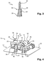
Figure 3 shows a schematic sectional view of a fixing pin of the motor fastening fromFigure 2 ; -
Figure 4 shows the control motor assembly fromFigure 1 after the forming of the free end portions of the fixing pins in accordance with a method according to the invention; -
Figure 5 shows a schematic partial sectional view of the control motor assembly according to the invention during a method according to the invention for the replacement of the control motor; -
Figure 6 shows a method step of said method in a schematic perspective illustration; -
Figures 7 and 8 show the motor fastening fromFigure 2 with a replacement control motor in a perspective illustration and in a sectional view; and -
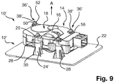
Figure 9 shows a motor fastening according to the invention with a placed-on control motor according to a second embodiment. -
Figures 1 to 8 show acontrol motor assembly 10 and amotor fastening 12 according to a first embodiment, whilstFigure 9 shows a control motor assembly 10' according to a second embodiment. - The
control motor assembly 10 consists here of themotor fastening 12 and acontrol motor 14 fastened thereto. In this example, in addition to theactual drive 16, which can be an electric motor, for example a servomotor or stepper motor, thecontrol motor 14 also comprises a plug socket and also the rest of the electrical contact connection of theactual drive 16 in order to supply the latter with power, and also ahousing 18 in which thedrive 16 is accommodated and which has a plurality of fastening elements on its circumferential edge, said fastening elements each comprising a through opening 20 (also seeFigure 6 ). The throughopenings 20 are formed here at the axially upper edge of thehousing 18 of thecontrol motor 14 in cylindrical sockets in the housing 18 (also seeFigure 6 ) . - The
motor fastening 12 comprises a plate-like support 22 from which a plurality of fixingpins 24 protrude. In this example, four individual fixing pins 24 are provided which each protrude perpendicularly from thesupport 22 and which are distributed over the surface of thesupport 22. All four fixingpins 24 are oriented parallel to one another. All of the fixing pins 24 are formed here from a suitable plastic, for example a thermoplastic, integrally with thesupport 22 in an injection-moulding process. - The
support 22 is provided with anopening 26 through which, in the mounted state, a spindle (not illustrated) of an adjustable flap in an air duct or a distributor housing of a vehicle heating, ventilating and/or air-conditioning system can protrude, said spindle being connected to thedrive 16 of thecontrol motor 14 when thecontrol motor 14 is mounted on themotor fastening 12. - The entire motor fastening 12 can already be integrated in the wall of a component, for example of an air duct or a distributor housing, but can also be manufactured as a separate part and subsequently fitted onto a component.
- For the fastening of the
control motor 14 on themotor fastening 12, thecontrol motor 14 is placed onto the fixing pins 24 in such a manner that the latter protrude through the throughopenings 20. The fixing pins 24 ensure an exact lateral positioning of thecontrol motor 14, and therefore a spindle protruding through theopening 26 in thesupport 22 comes exactly into engagement with a drive pinion of thedrive 16. - Each fixing
pin 24 has ashoulder 28 on which thecontrol motor 14 rests, and therefore the axial position of thecontrol motor 14 with respect to themotor fastening 12 is also exactly predetermined. - At the transition to the
support 22, a plurality of radially protruding triangular supportingribs 30 are provided on each fixingpin 24 and serve to increase the lateral stability of the fixingpin 24. The supportingribs 30 end axially below theshoulder 28 and do not come into contact with thecontrol motor 14. - Above the
shoulder 28, the fixingpin 24 tapers, and therefore its diameter is smaller than that of theshoulder 28 and forms a solidfree end portion 32. During the initial installation of acontrol motor 14, said end portion is initially of a length such that it projects clearly beyond an axially upper edge of the throughopening 20 in thecontrol motor 14, as can be seen inFigure 1 . Thefree end portion 32 tapers towards its free end, but is otherwise cylindrical. - In the interior of the fixing
pin 24, acentral opening 34 with a diameter which is cylindrical or tapers conically towards thesupport 22 runs from theshoulder 28 as far as the surface of thesupport 22, the object of which opening is also described further on. - After the
control motor 14 has been placed on the fixing pins 24 and has therefore taken up its final position both in the axial direction A and also perpendicularly thereto in lateral directions, thefree end portions 32 of the fixing pins 24 are formed by a suitable tool (not illustrated) in a heat forming process in such a manner that they take on the shape of a radially thickenedhead 36. The diameter of thehead 36 is larger than that of the throughopening 20, and therefore thecontrol motor 14 can no longer be lifted off upwards from the fixing pins 24. Thehead 36 is formed axially so close to the upper edge of the throughopening 20 that thecontrol motor 14 is fixed in the axial direction A to themotor fastening 12 in a substantially play-free manner. - After this step, the installation of the
control motor 14 on themotor fastening 12 is ended, and thecontrol motor assembly 10 is finished. - A
tool engagement surface 38, herein the form of a hexagon stub, is formed on the radially thickenedhead 36 during the forming. - If, after the initial installation, the
control motor 14 in the vehicle air-conditioning system is intended to be replaced, a suitable tool is fitted to thetool engagement surface 38 of thehead 36 and, via the lever action of said tool, thehead 36 is sheared off or broken off (indicated inFigure 6 ), from the rest of the fixingpin 24. - The fixing
pin 24 has a predeterminedbreaking point 40 which is arranged here in the region of theshoulder 28. At this point, the material of the fixingpin 24 tears or breaks, and thehead 36 can be removed together with the rest of thefree end portion 32 hanging integrally thereon. This is illustrated inFigures 5 and 6 . By removal of thehead 36, thecentral opening 34 in the interior of the fixingpin 24 is accessible. - The
old control motor 14 can now be lifted off from the fixing pins 24 and themotor fastening 12, and anew control motor 14 is placed onto the fixing pins 24 in such a manner that the throughopenings 20 rest on theshoulders 28 of the now shortened fixing pins 24. This is shown inFigure 7 and 8 . - For the fastening of the
new control motor 14, ascrew 42 is now plugged through the throughopening 20 and screwed into thecentral opening 34. The inner diameter of thecentral opening 34 is of course selected here in such a manner that the screw can grip securely. Since themotor fastening 12 including the fixing pins 24 is injection moulded from a plastic, thescrews 42 can cut into the wall of thecentral opening 34 and are thus securely held in the fixingpin 24. In this manner, the replacedcontrol motor 14 can be securely fixed to themotor fastening 12 by screw connections at all of the fixing pins 24 which are present. -
Figure 9 shows a second embodiment. In contrast to the first embodiment instead of an initiallycylindrical end portion 32 running rectilinearly, the fixing pins 24' already have a radially thickened head 36' formed at their upper end. - The head 36' consists of two latching
arms arms surface 56 at their axially lower end, i.e. directed towards thesupport 22, said latching surface protruding radially over the axially adjoining region (not illustrated) of the fixing pin 24'. - During the initial installation of the
control motor 14, the latter is placed with the throughopenings 20 onto the heads 36' of the fixing pins 24' and pushed in the direction of thesupport 22. The two latchingarms openings 20 can pass the head 36'. After the axially upper edge of the throughopening 20 has released the latching surfaces 56 again, the latchingarms opening 20. In this manner, thecontrol motor 14 is fixed securely and without play on the motor fastening 12' by means of a single push-in movement. - If the
control motor 14 is intended to be replaced, the head 36' is removed with a suitable tool, for example by a screwdriver being introduced into the gap between the latchingarms arms - Also in this case, a predetermined breaking point (not illustrated separately here) at which the latching
arms shoulder 28 below the latchingsurface 56. As in the previously described exemplary embodiment, a central opening in the interior of the fixing pin 24' is accessible, into which, after theold control motor 14 is removed and a newreplacement control motor 14 is placed on, screws are screwed in order to fasten thenew control motor 14 to the remaining parts of the fixing pins 24'.
Claims (11)
- Motor fastening of a control motor (14) in a vehicle heating, ventilating and/or air-conditioning system, with a plate-like support (22) on which at least one fixing pin (24; 24') is provided which protrudes from the support (22) and serves to be plugged through a through opening (20) in the control motor (14), wherein the fixing pin (24; 24') has a free end portion (32) which protrudes beyond the through opening (20) in the control motor (14) and which, in the mounted state, has a radially thickened head (36; 36') for the axial holding of the control motor (14) and which is an integral part of the fixing pin (24; 24') characterized in that the fixing pin (24; 24') has a predetermined breaking point (40) which lies below the head (36; 36').
- Motor fastening according to Claim 1, characterized in that the fixing pin (24; 24') has a central opening (34) which extends at least as far as the predetermined breaking point and is exposed after the end portion is broken off.
- Motor fastening according to one of the preceding claims, characterized in that the free end portion (32) is deformed to form a radially thickened head (36) by means of a forming process.
- Motor fastening according to one of the preceding claims, characterized in that the head (36') comprises two latching arms (50, 52), in particular latching hooks, which are movable in the radial direction and, after the control motor (14) is plugged on, engage behind an edge of the through opening (20).
- Motor fastening according to one of the preceding claims, characterized in that the head (36; 36') has a non-circular, torque-transmitting tool engagement surface (38; 38'), in particular a polygonal outer surface or a plug-in opening for a screwdriver.
- Motor fastening according to one of the preceding claims, characterized in that the fixing pin (24; 24') has a shoulder (28) on which the control motor (14) rests when the latter is placed onto the fixing pin (24; 24').
- Motor fastening according to one of the preceding claims, characterized in that a plurality of fixing pins (24; 24') with a radially thickened head (36; 36') are provided.
- Control motor assembly with a motor fastening (12; 12') according to one of the preceding claims, wherein a plurality of fixing pins (24; 24') are provided, and with a control motor (14) which is placed onto the fixing pins (24; 24') such that the fixing pins (24; 24') protrude through the through openings (20) in the control motor (14), wherein the radially thickened heads (36; 36') fix the control motor (14) on the motor fastening (12; 12') in the axial direction (A).
- Method for fastening a control motor (14) to a motor fastening (12) according to one of the preceding claims, unless referred back to Claim 3, characterized by the following steps:- the control motor (14) is placed onto the at least one fixing pin (24) of the motor fastening (12) in such a manner that the free end portion (32) of the fixing pin (24) protrudes through the through opening (20), and- the free end portion (32) is formed into a head (36) which has a larger diameter than the through opening (20), in order to fix the control motor (14) to the motor fastening (12).
- Method according to Claim9, characterized in that, during the forming of the free end portion (32), a tool engagement surface (38) is formed on the head (36).
- Method for replacing a control motor (14) which is fixed on a motor fastening (12; 12') according to one of Claims 1 to 7, wherein the control motor (14) is plugged onto the at least one fixing pin (24; 24') of the motor fastening (12; 12'), and the free end portion (32) of the fixing pin (24; 24') has a radially thickened head (36; 36') which is formed integrally with the end portion (32) and holds the control motor (14) axially in the motor fastening (12; 12'), with the following steps:- a tool is fitted on a tool engagement surface (38; 38') on the head (36; 36') in order to sever the head (36; 36') at a predetermined breaking point (40), wherein a central opening (34) in the fixing pin (24; 24') is exposed,- the previous control motor (14) is removed from the fixing pin (24; 24'),- a new control motor (14) is plugged onto the fixing pin (24; 24'), and- the new control motor (14) is fastened to the fixing pin (24; 24') with a screw (42), wherein the screw (42) engages through the through opening (20) in the control motor (14) into the central opening (34) in the fixing pin (24; 24').
Applications Claiming Priority (2)
| Application Number | Priority Date | Filing Date | Title |
|---|---|---|---|
| DE102016111145.7A DE102016111145A1 (en) | 2016-06-17 | 2016-06-17 | Engine mounting, actuator assembly, and method of attaching and replacing a servomotor in a vehicle heating, ventilation, and / or air conditioning system |
| PCT/EP2017/063646 WO2017215974A1 (en) | 2016-06-17 | 2017-06-06 | Motor fastening, control motor assembly and methods for fastening and for replacing a control motor in a vehicle heating, ventilating and/or air-conditioning system |
Publications (2)
| Publication Number | Publication Date |
|---|---|
| EP3471977A1 EP3471977A1 (en) | 2019-04-24 |
| EP3471977B1 true EP3471977B1 (en) | 2020-12-30 |
Family
ID=59021494
Family Applications (1)
| Application Number | Title | Priority Date | Filing Date |
|---|---|---|---|
| EP17728527.7A Active EP3471977B1 (en) | 2016-06-17 | 2017-06-06 | Assembly and methods for fastening and for replacing a control motor in a vehicle heating, ventilating and/or air-conditioning system |
Country Status (3)
| Country | Link |
|---|---|
| EP (1) | EP3471977B1 (en) |
| DE (1) | DE102016111145A1 (en) |
| WO (1) | WO2017215974A1 (en) |
Cited By (2)
| Publication number | Priority date | Publication date | Assignee | Title |
|---|---|---|---|---|
| KR20230070656A (en) * | 2021-11-15 | 2023-05-23 | 한온시스템 주식회사 | Air conditioner for vehicle |
| FR3146094A1 (en) * | 2023-02-23 | 2024-08-30 | Valeo Systemes Thermiques | Device for a motor vehicle, said device comprising a system for attaching an actuator to a support |
Families Citing this family (1)
| Publication number | Priority date | Publication date | Assignee | Title |
|---|---|---|---|---|
| JP6256136B2 (en) * | 2014-03-24 | 2018-01-10 | 株式会社デンソー | Air conditioner |
Family Cites Families (2)
| Publication number | Priority date | Publication date | Assignee | Title |
|---|---|---|---|---|
| FR2743118B1 (en) * | 1995-12-27 | 1998-02-13 | Valeo Climatisation | DEVICE FOR FIXING A GEAR MOTOR ON A VEHICLE HEATING BOX |
| DE10011236C2 (en) * | 2000-03-08 | 2002-02-21 | Valeo Klimasysteme Gmbh | fastening device |
-
2016
- 2016-06-17 DE DE102016111145.7A patent/DE102016111145A1/en not_active Withdrawn
-
2017
- 2017-06-06 WO PCT/EP2017/063646 patent/WO2017215974A1/en not_active Ceased
- 2017-06-06 EP EP17728527.7A patent/EP3471977B1/en active Active
Non-Patent Citations (1)
| Title |
|---|
| None * |
Cited By (2)
| Publication number | Priority date | Publication date | Assignee | Title |
|---|---|---|---|---|
| KR20230070656A (en) * | 2021-11-15 | 2023-05-23 | 한온시스템 주식회사 | Air conditioner for vehicle |
| FR3146094A1 (en) * | 2023-02-23 | 2024-08-30 | Valeo Systemes Thermiques | Device for a motor vehicle, said device comprising a system for attaching an actuator to a support |
Also Published As
| Publication number | Publication date |
|---|---|
| DE102016111145A1 (en) | 2017-12-21 |
| WO2017215974A1 (en) | 2017-12-21 |
| EP3471977A1 (en) | 2019-04-24 |
Similar Documents
| Publication | Publication Date | Title |
|---|---|---|
| EP1452748B1 (en) | Fastener for connecting and spacing parts | |
| EP3471977A1 (en) | Motor fastening, control motor assembly and methods for fastening and for replacing a control motor in a vehicle heating, ventilating and/or air-conditioning system | |
| US20200353812A1 (en) | Active grille, scalable design | |
| RU2616477C2 (en) | Device for riveting of aircraft fuselage | |
| US2403566A (en) | Lock nut | |
| EP2793322B1 (en) | Power socket and contact unit used therefor | |
| EP3769331B1 (en) | A power distribution unit, such as a fuse box for a vehicle | |
| JPH08512122A (en) | Fixing system | |
| WO2011023500A1 (en) | Receiving device for a stepping motor | |
| EP3668272A1 (en) | Holding body, heating apparatus and method | |
| EP1523087A1 (en) | Electric motor with attached electronic housing | |
| US9541110B2 (en) | Detachable holder | |
| US12398746B2 (en) | Fastening module, method for producing a fastening module, and method for connecting two components to a fastening module | |
| CN203068755U (en) | Air conditioner | |
| US4519235A (en) | Louver tool | |
| US6055728A (en) | Automatically assembling method to connect plural members | |
| EP3556706B1 (en) | Bracket assembly adjustable to the thickness of the wing of a lift guide | |
| US11913621B2 (en) | Vehicle headlight fan system with bayonet connectors | |
| WO2015060925A1 (en) | Clamp device for use with a decompression panel in an aircraft assembly | |
| JP2004090161A (en) | Structure of punching die for punching machine | |
| JP6973002B2 (en) | Vehicle air conditioner and its disassembly method | |
| JP2001099117A (en) | Fastener | |
| US8516677B2 (en) | Method for removing an auxiliary contact device from a motor controller unit | |
| CN102483632B (en) | Actuator attachment for actuating a radiator valve | |
| CN120812870A (en) | Screw fastening of housing components |
Legal Events
| Date | Code | Title | Description |
|---|---|---|---|
| STAA | Information on the status of an ep patent application or granted ep patent |
Free format text: STATUS: UNKNOWN |
|
| STAA | Information on the status of an ep patent application or granted ep patent |
Free format text: STATUS: THE INTERNATIONAL PUBLICATION HAS BEEN MADE |
|
| PUAI | Public reference made under article 153(3) epc to a published international application that has entered the european phase |
Free format text: ORIGINAL CODE: 0009012 |
|
| STAA | Information on the status of an ep patent application or granted ep patent |
Free format text: STATUS: REQUEST FOR EXAMINATION WAS MADE |
|
| 17P | Request for examination filed |
Effective date: 20181211 |
|
| AK | Designated contracting states |
Kind code of ref document: A1 Designated state(s): AL AT BE BG CH CY CZ DE DK EE ES FI FR GB GR HR HU IE IS IT LI LT LU LV MC MK MT NL NO PL PT RO RS SE SI SK SM TR |
|
| AX | Request for extension of the european patent |
Extension state: BA ME |
|
| DAV | Request for validation of the european patent (deleted) | ||
| DAX | Request for extension of the european patent (deleted) | ||
| GRAP | Despatch of communication of intention to grant a patent |
Free format text: ORIGINAL CODE: EPIDOSNIGR1 |
|
| STAA | Information on the status of an ep patent application or granted ep patent |
Free format text: STATUS: GRANT OF PATENT IS INTENDED |
|
| INTG | Intention to grant announced |
Effective date: 20200925 |
|
| GRAS | Grant fee paid |
Free format text: ORIGINAL CODE: EPIDOSNIGR3 |
|
| GRAA | (expected) grant |
Free format text: ORIGINAL CODE: 0009210 |
|
| STAA | Information on the status of an ep patent application or granted ep patent |
Free format text: STATUS: THE PATENT HAS BEEN GRANTED |
|
| AK | Designated contracting states |
Kind code of ref document: B1 Designated state(s): AL AT BE BG CH CY CZ DE DK EE ES FI FR GB GR HR HU IE IS IT LI LT LU LV MC MK MT NL NO PL PT RO RS SE SI SK SM TR |
|
| REG | Reference to a national code |
Ref country code: GB Ref legal event code: FG4D |
|
| REG | Reference to a national code |
Ref country code: AT Ref legal event code: REF Ref document number: 1349587 Country of ref document: AT Kind code of ref document: T Effective date: 20210115 |
|
| REG | Reference to a national code |
Ref country code: DE Ref legal event code: R096 Ref document number: 602017030454 Country of ref document: DE |
|
| REG | Reference to a national code |
Ref country code: IE Ref legal event code: FG4D |
|
| PG25 | Lapsed in a contracting state [announced via postgrant information from national office to epo] |
Ref country code: FI Free format text: LAPSE BECAUSE OF FAILURE TO SUBMIT A TRANSLATION OF THE DESCRIPTION OR TO PAY THE FEE WITHIN THE PRESCRIBED TIME-LIMIT Effective date: 20201230 Ref country code: GR Free format text: LAPSE BECAUSE OF FAILURE TO SUBMIT A TRANSLATION OF THE DESCRIPTION OR TO PAY THE FEE WITHIN THE PRESCRIBED TIME-LIMIT Effective date: 20210331 Ref country code: RS Free format text: LAPSE BECAUSE OF FAILURE TO SUBMIT A TRANSLATION OF THE DESCRIPTION OR TO PAY THE FEE WITHIN THE PRESCRIBED TIME-LIMIT Effective date: 20201230 Ref country code: NO Free format text: LAPSE BECAUSE OF FAILURE TO SUBMIT A TRANSLATION OF THE DESCRIPTION OR TO PAY THE FEE WITHIN THE PRESCRIBED TIME-LIMIT Effective date: 20210330 |
|
| REG | Reference to a national code |
Ref country code: AT Ref legal event code: MK05 Ref document number: 1349587 Country of ref document: AT Kind code of ref document: T Effective date: 20201230 |
|
| PG25 | Lapsed in a contracting state [announced via postgrant information from national office to epo] |
Ref country code: BG Free format text: LAPSE BECAUSE OF FAILURE TO SUBMIT A TRANSLATION OF THE DESCRIPTION OR TO PAY THE FEE WITHIN THE PRESCRIBED TIME-LIMIT Effective date: 20210330 Ref country code: LV Free format text: LAPSE BECAUSE OF FAILURE TO SUBMIT A TRANSLATION OF THE DESCRIPTION OR TO PAY THE FEE WITHIN THE PRESCRIBED TIME-LIMIT Effective date: 20201230 Ref country code: SE Free format text: LAPSE BECAUSE OF FAILURE TO SUBMIT A TRANSLATION OF THE DESCRIPTION OR TO PAY THE FEE WITHIN THE PRESCRIBED TIME-LIMIT Effective date: 20201230 |
|
| REG | Reference to a national code |
Ref country code: NL Ref legal event code: MP Effective date: 20201230 |
|
| PG25 | Lapsed in a contracting state [announced via postgrant information from national office to epo] |
Ref country code: HR Free format text: LAPSE BECAUSE OF FAILURE TO SUBMIT A TRANSLATION OF THE DESCRIPTION OR TO PAY THE FEE WITHIN THE PRESCRIBED TIME-LIMIT Effective date: 20201230 |
|
| REG | Reference to a national code |
Ref country code: LT Ref legal event code: MG9D |
|
| PG25 | Lapsed in a contracting state [announced via postgrant information from national office to epo] |
Ref country code: CZ Free format text: LAPSE BECAUSE OF FAILURE TO SUBMIT A TRANSLATION OF THE DESCRIPTION OR TO PAY THE FEE WITHIN THE PRESCRIBED TIME-LIMIT Effective date: 20201230 Ref country code: EE Free format text: LAPSE BECAUSE OF FAILURE TO SUBMIT A TRANSLATION OF THE DESCRIPTION OR TO PAY THE FEE WITHIN THE PRESCRIBED TIME-LIMIT Effective date: 20201230 Ref country code: LT Free format text: LAPSE BECAUSE OF FAILURE TO SUBMIT A TRANSLATION OF THE DESCRIPTION OR TO PAY THE FEE WITHIN THE PRESCRIBED TIME-LIMIT Effective date: 20201230 Ref country code: RO Free format text: LAPSE BECAUSE OF FAILURE TO SUBMIT A TRANSLATION OF THE DESCRIPTION OR TO PAY THE FEE WITHIN THE PRESCRIBED TIME-LIMIT Effective date: 20201230 Ref country code: SK Free format text: LAPSE BECAUSE OF FAILURE TO SUBMIT A TRANSLATION OF THE DESCRIPTION OR TO PAY THE FEE WITHIN THE PRESCRIBED TIME-LIMIT Effective date: 20201230 Ref country code: PT Free format text: LAPSE BECAUSE OF FAILURE TO SUBMIT A TRANSLATION OF THE DESCRIPTION OR TO PAY THE FEE WITHIN THE PRESCRIBED TIME-LIMIT Effective date: 20210430 |
|
| PG25 | Lapsed in a contracting state [announced via postgrant information from national office to epo] |
Ref country code: AT Free format text: LAPSE BECAUSE OF FAILURE TO SUBMIT A TRANSLATION OF THE DESCRIPTION OR TO PAY THE FEE WITHIN THE PRESCRIBED TIME-LIMIT Effective date: 20201230 Ref country code: PL Free format text: LAPSE BECAUSE OF FAILURE TO SUBMIT A TRANSLATION OF THE DESCRIPTION OR TO PAY THE FEE WITHIN THE PRESCRIBED TIME-LIMIT Effective date: 20201230 |
|
| PG25 | Lapsed in a contracting state [announced via postgrant information from national office to epo] |
Ref country code: IS Free format text: LAPSE BECAUSE OF FAILURE TO SUBMIT A TRANSLATION OF THE DESCRIPTION OR TO PAY THE FEE WITHIN THE PRESCRIBED TIME-LIMIT Effective date: 20210430 |
|
| REG | Reference to a national code |
Ref country code: DE Ref legal event code: R097 Ref document number: 602017030454 Country of ref document: DE |
|
| PG25 | Lapsed in a contracting state [announced via postgrant information from national office to epo] |
Ref country code: AL Free format text: LAPSE BECAUSE OF FAILURE TO SUBMIT A TRANSLATION OF THE DESCRIPTION OR TO PAY THE FEE WITHIN THE PRESCRIBED TIME-LIMIT Effective date: 20201230 Ref country code: IT Free format text: LAPSE BECAUSE OF FAILURE TO SUBMIT A TRANSLATION OF THE DESCRIPTION OR TO PAY THE FEE WITHIN THE PRESCRIBED TIME-LIMIT Effective date: 20201230 |
|
| PLBE | No opposition filed within time limit |
Free format text: ORIGINAL CODE: 0009261 |
|
| STAA | Information on the status of an ep patent application or granted ep patent |
Free format text: STATUS: NO OPPOSITION FILED WITHIN TIME LIMIT |
|
| PG25 | Lapsed in a contracting state [announced via postgrant information from national office to epo] |
Ref country code: DK Free format text: LAPSE BECAUSE OF FAILURE TO SUBMIT A TRANSLATION OF THE DESCRIPTION OR TO PAY THE FEE WITHIN THE PRESCRIBED TIME-LIMIT Effective date: 20201230 |
|
| 26N | No opposition filed |
Effective date: 20211001 |
|
| PG25 | Lapsed in a contracting state [announced via postgrant information from national office to epo] |
Ref country code: MC Free format text: LAPSE BECAUSE OF FAILURE TO SUBMIT A TRANSLATION OF THE DESCRIPTION OR TO PAY THE FEE WITHIN THE PRESCRIBED TIME-LIMIT Effective date: 20201230 Ref country code: ES Free format text: LAPSE BECAUSE OF FAILURE TO SUBMIT A TRANSLATION OF THE DESCRIPTION OR TO PAY THE FEE WITHIN THE PRESCRIBED TIME-LIMIT Effective date: 20201230 |
|
| REG | Reference to a national code |
Ref country code: CH Ref legal event code: PL |
|
| GBPC | Gb: european patent ceased through non-payment of renewal fee |
Effective date: 20210606 |
|
| PG25 | Lapsed in a contracting state [announced via postgrant information from national office to epo] |
Ref country code: SI Free format text: LAPSE BECAUSE OF FAILURE TO SUBMIT A TRANSLATION OF THE DESCRIPTION OR TO PAY THE FEE WITHIN THE PRESCRIBED TIME-LIMIT Effective date: 20201230 |
|
| REG | Reference to a national code |
Ref country code: BE Ref legal event code: MM Effective date: 20210630 |
|
| PG25 | Lapsed in a contracting state [announced via postgrant information from national office to epo] |
Ref country code: LU Free format text: LAPSE BECAUSE OF NON-PAYMENT OF DUE FEES Effective date: 20210606 |
|
| PG25 | Lapsed in a contracting state [announced via postgrant information from national office to epo] |
Ref country code: LI Free format text: LAPSE BECAUSE OF NON-PAYMENT OF DUE FEES Effective date: 20210630 Ref country code: IE Free format text: LAPSE BECAUSE OF NON-PAYMENT OF DUE FEES Effective date: 20210606 Ref country code: GB Free format text: LAPSE BECAUSE OF NON-PAYMENT OF DUE FEES Effective date: 20210606 Ref country code: CH Free format text: LAPSE BECAUSE OF NON-PAYMENT OF DUE FEES Effective date: 20210630 |
|
| PG25 | Lapsed in a contracting state [announced via postgrant information from national office to epo] |
Ref country code: IS Free format text: LAPSE BECAUSE OF FAILURE TO SUBMIT A TRANSLATION OF THE DESCRIPTION OR TO PAY THE FEE WITHIN THE PRESCRIBED TIME-LIMIT Effective date: 20210430 |
|
| PG25 | Lapsed in a contracting state [announced via postgrant information from national office to epo] |
Ref country code: BE Free format text: LAPSE BECAUSE OF NON-PAYMENT OF DUE FEES Effective date: 20210630 |
|
| PG25 | Lapsed in a contracting state [announced via postgrant information from national office to epo] |
Ref country code: NL Free format text: LAPSE BECAUSE OF NON-PAYMENT OF DUE FEES Effective date: 20201230 Ref country code: CY Free format text: LAPSE BECAUSE OF FAILURE TO SUBMIT A TRANSLATION OF THE DESCRIPTION OR TO PAY THE FEE WITHIN THE PRESCRIBED TIME-LIMIT Effective date: 20201230 |
|
| PG25 | Lapsed in a contracting state [announced via postgrant information from national office to epo] |
Ref country code: SM Free format text: LAPSE BECAUSE OF FAILURE TO SUBMIT A TRANSLATION OF THE DESCRIPTION OR TO PAY THE FEE WITHIN THE PRESCRIBED TIME-LIMIT Effective date: 20201230 Ref country code: HU Free format text: LAPSE BECAUSE OF FAILURE TO SUBMIT A TRANSLATION OF THE DESCRIPTION OR TO PAY THE FEE WITHIN THE PRESCRIBED TIME-LIMIT; INVALID AB INITIO Effective date: 20170606 |
|
| P01 | Opt-out of the competence of the unified patent court (upc) registered |
Effective date: 20230630 |
|
| PG25 | Lapsed in a contracting state [announced via postgrant information from national office to epo] |
Ref country code: MK Free format text: LAPSE BECAUSE OF FAILURE TO SUBMIT A TRANSLATION OF THE DESCRIPTION OR TO PAY THE FEE WITHIN THE PRESCRIBED TIME-LIMIT Effective date: 20201230 |
|
| PG25 | Lapsed in a contracting state [announced via postgrant information from national office to epo] |
Ref country code: MT Free format text: LAPSE BECAUSE OF FAILURE TO SUBMIT A TRANSLATION OF THE DESCRIPTION OR TO PAY THE FEE WITHIN THE PRESCRIBED TIME-LIMIT Effective date: 20201230 |
|
| PGFP | Annual fee paid to national office [announced via postgrant information from national office to epo] |
Ref country code: DE Payment date: 20250617 Year of fee payment: 9 |
|
| PGFP | Annual fee paid to national office [announced via postgrant information from national office to epo] |
Ref country code: FR Payment date: 20250630 Year of fee payment: 9 |
|
| PG25 | Lapsed in a contracting state [announced via postgrant information from national office to epo] |
Ref country code: TR Free format text: LAPSE BECAUSE OF FAILURE TO SUBMIT A TRANSLATION OF THE DESCRIPTION OR TO PAY THE FEE WITHIN THE PRESCRIBED TIME-LIMIT Effective date: 20201230 |