EP3471920B1 - Improvements to multi-jack tensioners - Google Patents
Improvements to multi-jack tensioners Download PDFInfo
- Publication number
- EP3471920B1 EP3471920B1 EP17814153.7A EP17814153A EP3471920B1 EP 3471920 B1 EP3471920 B1 EP 3471920B1 EP 17814153 A EP17814153 A EP 17814153A EP 3471920 B1 EP3471920 B1 EP 3471920B1
- Authority
- EP
- European Patent Office
- Prior art keywords
- body portion
- hydraulic
- bearing member
- jack
- piston
- Prior art date
- Legal status (The legal status is an assumption and is not a legal conclusion. Google has not performed a legal analysis and makes no representation as to the accuracy of the status listed.)
- Active
Links
Images














Classifications
-
- B—PERFORMING OPERATIONS; TRANSPORTING
- B23—MACHINE TOOLS; METAL-WORKING NOT OTHERWISE PROVIDED FOR
- B23P—METAL-WORKING NOT OTHERWISE PROVIDED FOR; COMBINED OPERATIONS; UNIVERSAL MACHINE TOOLS
- B23P19/00—Machines for simply fitting together or separating metal parts or objects, or metal and non-metal parts, whether or not involving some deformation; Tools or devices therefor so far as not provided for in other classes
- B23P19/04—Machines for simply fitting together or separating metal parts or objects, or metal and non-metal parts, whether or not involving some deformation; Tools or devices therefor so far as not provided for in other classes for assembling or disassembling parts
- B23P19/06—Screw or nut setting or loosening machines
- B23P19/067—Bolt tensioners
-
- G—PHYSICS
- G21—NUCLEAR PHYSICS; NUCLEAR ENGINEERING
- G21C—NUCLEAR REACTORS
- G21C13/00—Pressure vessels; Containment vessels; Containment in general
- G21C13/02—Details
- G21C13/06—Sealing-plugs
-
- B—PERFORMING OPERATIONS; TRANSPORTING
- B25—HAND TOOLS; PORTABLE POWER-DRIVEN TOOLS; MANIPULATORS
- B25B—TOOLS OR BENCH DEVICES NOT OTHERWISE PROVIDED FOR, FOR FASTENING, CONNECTING, DISENGAGING, OR HOLDING
- B25B29/00—Accessories
- B25B29/02—Bolt tensioners
-
- F—MECHANICAL ENGINEERING; LIGHTING; HEATING; WEAPONS; BLASTING
- F16—ENGINEERING ELEMENTS AND UNITS; GENERAL MEASURES FOR PRODUCING AND MAINTAINING EFFECTIVE FUNCTIONING OF MACHINES OR INSTALLATIONS; THERMAL INSULATION IN GENERAL
- F16B—DEVICES FOR FASTENING OR SECURING CONSTRUCTIONAL ELEMENTS OR MACHINE PARTS TOGETHER, e.g. NAILS, BOLTS, CIRCLIPS, CLAMPS, CLIPS OR WEDGES; JOINTS OR JOINTING
- F16B31/00—Screwed connections specially modified in view of tensile load; Break-bolts
- F16B31/04—Screwed connections specially modified in view of tensile load; Break-bolts for maintaining a tensile load
-
- F—MECHANICAL ENGINEERING; LIGHTING; HEATING; WEAPONS; BLASTING
- F16—ENGINEERING ELEMENTS AND UNITS; GENERAL MEASURES FOR PRODUCING AND MAINTAINING EFFECTIVE FUNCTIONING OF MACHINES OR INSTALLATIONS; THERMAL INSULATION IN GENERAL
- F16D—COUPLINGS FOR TRANSMITTING ROTATION; CLUTCHES; BRAKES
- F16D1/00—Couplings for rigidly connecting two coaxial shafts or other movable machine elements
- F16D1/02—Couplings for rigidly connecting two coaxial shafts or other movable machine elements for connecting two abutting shafts or the like
- F16D1/033—Couplings for rigidly connecting two coaxial shafts or other movable machine elements for connecting two abutting shafts or the like by clamping together two faces perpendicular to the axis of rotation, e.g. with bolted flanges
-
- Y—GENERAL TAGGING OF NEW TECHNOLOGICAL DEVELOPMENTS; GENERAL TAGGING OF CROSS-SECTIONAL TECHNOLOGIES SPANNING OVER SEVERAL SECTIONS OF THE IPC; TECHNICAL SUBJECTS COVERED BY FORMER USPC CROSS-REFERENCE ART COLLECTIONS [XRACs] AND DIGESTS
- Y02—TECHNOLOGIES OR APPLICATIONS FOR MITIGATION OR ADAPTATION AGAINST CLIMATE CHANGE
- Y02E—REDUCTION OF GREENHOUSE GAS [GHG] EMISSIONS, RELATED TO ENERGY GENERATION, TRANSMISSION OR DISTRIBUTION
- Y02E30/00—Energy generation of nuclear origin
- Y02E30/30—Nuclear fission reactors
Definitions
- a multi jack tensioner including: a body portion formed to engage an elongate fastening member or integrally formed therewith;
- the load bearing member is formed as a piston arranged to cooperate with the body.
- the hydraulic MJT 10 is in the form of a nut and generally comprises an annular body 20 with central axis "L" having a concentric circular threaded hole 25 formed therethrough to receive a stud or bolt (not shown).
- the annular body 20 is formed with a concentric polar array of threaded jack bolt holes therethrough in similar fashions to holes 201 as illustrated in FIG. 1 .
- FIG. 12 a hydraulic line 111 is applied to the hydraulic port 60 using a suitable hydraulic nipple and coupler.
- the hydraulic line 111 is coupled to a source of hydraulic power.
- FIG. 13 illustrates how upon applying hydraulic pressure via the line 111 the hydraulic chamber 50 fills with hydraulic fluid thereby forcing the piston 40 apart from the body 20 to a separation distance "D" thereby tensioning the bolt as indicated by arrows 112a, 112b.
- the underside of the load bearing member which in the present example comprises piston 40, bears down upon the outside, i.e. the topside as shown in FIG. 13 , of the first flange 102.
- FIGS. 17A, 17B and 17C depict a further nut-style hydraulic MJT fastener 10A and FIGS. 18A, 18B which illustrate a corresponding bolt-style embodiment of a hydraulic MJT fastener 10A'.
- the hydraulic MJTs 10A, 10A' may comprise an upper locking collar 70.
- a gap 75 is created between the body 20 and locking collar 70 when the pressure chamber 50 receives hydraulic fluid to generate the pre-load.
- the body 20 has an outside thread to threadingly engage the locking collar 70.
- the piston 40 which in this embodiment comprises the load bearing member against the workpiece to be joined, and the body 20 move apart.
- FIGS. 33A-33C depict a further embodiment of a nut-style hydraulic compression tool MJT 101 according to an embodiment of the present invention.
- MJT 101 has a two-part annular body 20 with a first inner part 20a having an annular recess 25 to receive a stud (not shown), and a plurality of jack bolts 30 spaced uniformly from a longitudinal central axis L at spaced apart locations about its outer periphery.
- a second part 20B of the two-part annular body 20 is threaded about the outside of the first part 20A.
- a load cell 90 locates beneath the outer part 20B of the body 20.
- a washer 64 locates within the annular load cell 90 concentric with the first part 20A of the annular body 20.
- the body may comprise drilled and tapped holes to threadedly engage each jack bolt.
- the jack bolt may comprise a socket-head cap screw.
- a person having ordinary skill in the art may appreciate that the number of jack bolts may be selected according to the desired stress that is to be imposed on the shank portion of the fastener.
- the jack bolts may be arranged in only one annular array but two or more annular arrays may be used to accommodate the desired number of jack bolts.
- the tool may comprise twenty-four jack bolts with twelve jack bolts spaced about each of the bolt centers in an alternating arrangement.
- the locking collar may comprise one of a lower collar type and an upper collar type.
- the hydraulic compression tool may comprise a lower locking collar including a piston having internal threads and external threads.
- the hydraulic compression tool may comprise an upper locking collar including a piston having internal threads and external threads.
- the external threads of the piston may engage mating threads of the locking collar.
- a gap between the body and locking collar may be created when the pressure chamber receives hydraulic fluid to generate the pre-load.
- the width of the gap may generally relate to the compression of the joint, gasket, if fitted, and the elongation of the stud.
- the locking collar may be tightened and the pressure may be released to transfer the pre-load to the locking collar.
- the hydraulic compression tool may comprise an upper locking collar including a plain bore load cell and a collar nut.
- the collar nut may comprise internal threads and external threads. The external threads may engage mating threads of the locking collar.
- a gap between the body and locking collar may be created when the pressure chamber receives hydraulic fluid to generate the pre-load.
- the width of the gap may generally relate to the compression of the joint, gasket, if fitted, and the elongation of the stud.
- the locking collar may be tightened and the pressure may be released to transfer the pre-load to the locking collar.
- the port may be positioned on the side of the piston because the load cell has a plain bore.
- the method may comprise threading a hydraulic compression tool onto each of the bolts of the vessel, wherein each of the hydraulic compression tools are in fluid communication with each other, and injecting hydraulic fluid into the chamber of each of the hydraulic compression tools to tension each of the bolts substantially simultaneously to the same preload.
- the load generated by the hydraulic compression tools may be evenly distributed around the joint such that a compression gasket may flow into any surface irregularities of the vessel to provide an improved seal relative to tightening the bolts individually.
- the plurality of jack bolts on each of the hydraulic compression tools may be tightened to the desired preload, and the hydraulic pressure may be released.
Landscapes
- Engineering & Computer Science (AREA)
- General Engineering & Computer Science (AREA)
- Mechanical Engineering (AREA)
- Physics & Mathematics (AREA)
- Plasma & Fusion (AREA)
- High Energy & Nuclear Physics (AREA)
- Hand Tools For Fitting Together And Separating, Or Other Hand Tools (AREA)
- Actuator (AREA)
Description
- The present disclosure generally relates to hydraulically assisted fastening and/or tensioning devices, and methods of using the same.
- A multi-jack bolt tensioner (MJT) may be used for tightening bolts, shafts, or studs in the oil and gas, energy, transportation, and mining industries, for example. The MJT may be used as a direct replacement for conventional nuts and bolts.
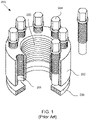
FIG. 1 is a partially cutaway version of a nut-style MJT 200. The MJT 200 comprises anannular body 202. Thebody 202 of the MJT 200 is formed with a threadedcentral hole 205 to receive a bolt, shaft, or stud. A polar array of threadedjack bolt holes 201, each disposed on a circle concentric with the central hole, pass though thebody 202. Correspondingjack bolts 204 traverse thejack bolt holes 201 and are threadedly received therein. The MJT 200 further includes a load bearing member in the form of a hardenedwasher 206 against which points of thejack bolts 204 abut in use. The hardenedwasher 206 bears against a workpiece being fastened. - As an alternative to the nut-style MJT of
FIG. 1 , bolt-style MJTs are also known. A bolt-style MJT generally comprises a body having a threaded shaft that may be used for blind tapped holes and counterbores. MJTs are commercially available from Superbolt, Carnegie PA. Further discussions of MJTs may be found inU.S. Pat. Nos. 4,622,730 ,RE33,490 ,4,927,305 ,5,075,950 ,5,083,889 and6,112,396 . -
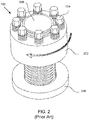
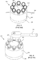
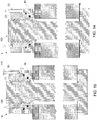
FIGS. 2 to 6 illustrate the use of the MJT 200. With reference toFIG. 2 , initially hardenedwasher 206 is installed onto thestud 208. Thebody 202 is then threaded onto thestud 208 until it seats against the hardenedwasher 206 to tension the joint. InFIG. 2 thejack bolts 204 are withdrawn so that their points do not extend out of thebody 202 of the MJT. Referring now toFIG. 3 , once thewasher 206 has been located over thestud 208 and the MJT 200 has been threaded onto the stud and into abutment with thewasher 206 then four of the jack bolts at 90 degrees apart (i.e. 12 o'clock, 6 o'clock, 9 o'clock and 3 o'clock as circled inFIG. 3 ) are tightened with a partial torque of 30-70% and this process is then repeated for the remaining four jack bolts. Applying partial torque evenly distributed to all of thejack bolts 204 serves to seat the hardenedwasher 206 against thecontact surface 209 to be fastened, e.g. a flange. With reference toFIG. 4 , at 100% target torque the same four jack bolts are then tightened. With reference toFIG. 5 , at 100% target torque all of thejack bolts 204 are tightened in a circular pattern. Referring now toFIG. 6 , all of thejack bolts 204 are tightened again with atorque wrench 212 for example until they stabilize (usually less than 10 degrees of rotation of eachjack bolt 204 is involved in this step). This step may need 2-4 additional passes around the jack bolts so that all of the jack bolts are incrementally tightened and at any one time there is no great imbalance of tension between them. - When the
jack bolts 204 are torqued, a tension preload develops evenly along thestud 208, and the axial forces by thejack bolts 204 and opposite reaction force of thestud 208 create a strong clamping force between the surfaces to be fastened together, such as opposed flanges for example. Applying the correct preload is desirable because a pretensioned bolt, shaft or stud may be capable of sustaining a greater load and may reduce the likelihood of the bolt, shaft, or stud loosening unintentionally due to e.g., vibration and/ or temperature cycling. - However, it will be realized that properly applying a MJT, as has been explained with reference to
FIGS. 2 to 6 , is a demanding and time consuming exercise. An experienced operator may take around five minutes to apply an MJT in the manner that has been discussed. It will be understood that where large plants are being installed there may be hundreds or thousands of MJTs to be fitted. In that case a saving of time for the installation of each MJT results in a very considerable saving of worker hours for the overall project at hand. Furthermore, ensuring that the jack bolts are tightened so that they uniformly and evenly apply force to the hardened washer is a somewhat demanding operation that requires applying torque to the jack bolts in a predetermined sequence. Where the sequence is not followed correctly one of the consequences is that there may be an imbalance in the tensioning of the jack bolts which potentially could lead to a catastrophic failure. - One MJT utilized in the prior art is described in
United States patent application No. 2003/0185642 (US2003/0185642 ).US2003/0185642 describes a load transmission device which transmit a load input to a load-receiving member through a pressure transmitting medium. The pressure transmitting medium is in the form of balls. A similar tensioning tool can also be seen indocument DE 10 2014 219643 A1 . According to said document, a tensioner is disclosed consisting of a separate, removable clamping device containing a pressure chamber that is attached to the body portion of the tensioner via matching threads, in order to apply a tensioning force to an elongated fastening member. - It would be advantageous if an apparatus were provided that allowed for the proper and faster placement of jack bolts of an MJT type fastener to thereby address the previously described problems.
- According to a first aspect of the present invention there is provided a multi jack tensioner including: a body portion formed to engage an elongate fastening member or integrally formed therewith;
- a load bearing member for applying force to a workpiece to be fastened and arranged for location about said fastening member adjacent the body portion;
- a pressure chamber formed between the load bearing member and the body portion arranged to displace the body portion from the load bearing member in response to hydraulic pressure; and
- a plurality of jack bolts extending between the body portion and the load bearing member adapted to displace the body portion from the load bearing member;
- wherein application of hydraulic pressure to the hydraulic chamber displaces the body portion from the load bearing member for tensioning' said fastening member and whereby subsequent tensioning of the fastening member is applied by operation of the jack bolts wherein the body portion and load bearing member are shaped to cooperate and define the pressure chamber therebetween, and wherein the plurality of jack bolts extend through the body portion to abut the loading bearing member.
- Preferably the body portion is formed with an axial recess to threadedly engage the elongate fastening member wherein the elongate fastening member comprises a bolt or stud.
- In some embodiments the body portion is integrally formed with the elongate fastening member.
- In some embodiments of the invention the load bearing member is formed as a piston arranged to cooperate with the body.
- Alternatively the load bearing member may be formed as a load cell with which a piston cooperates that forces the body in use.
- Preferably the plurality of jack bolts comprises an annular array of jack bolts threadedly received through holes formed spaced uniformly from a longitudinal central axis of the body at spaced apart locations about an outer surface thereof.
- In some embodiments of the invention a piston is slidingly received into the body, and a pressure chamber between the body and piston to receive hydraulic fluid through a port and a fluid passage, wherein when the pressure chamber receives hydraulic fluid, the body and piston axially separate.
- The invention encompasses embodiments wherein each of the plurality of jack bolts is in threaded engagement with the body portion and projects from the body portion into compressive engagement with the load bearing member.
- The load bearing member may comprise the piston, a load cell, and a washer.
- In one embodiment the load bearing member comprises a load cell.
- The loading bearing member comprises a washer in some embodiments of the invention.
- A locking collar may be provided for maintaining a distance between the load bearing member and the body subsequent to removal of the hydraulic pressure.
- In some embodiments at least one shim is provided for maintaining a distance between the load bearing member and the body subsequent to removal of the hydraulic pressure.
- A port for entry of the hydraulic pressure may be positioned on a side outer periphery of the load cell along a plane perpendicular to the longitudinal central axis that does not intersect any jack bolt.
- The port may be positioned on a side outer periphery of the load cell along a plane perpendicular to the longitudinal central axis that intersects two jack bolts.
- There is also disclosed a method for compressing first and second workpieces together comprising the steps of:
- passing an elongate fastening member through the first and second workpieces wherein a first end of the elongate fastening member is captured on an outer side of the first workpiece;
- tensioning the elongate fastening member by applying hydraulic pressure between said second end of said fastening member and an outer side of the second workpiece; and
- further tensioning the elongate member with jack bolts;
- whereby the tensioning of the elongate fastening member results in compressing the first and second workpieces towards each other.
- According to another aspect of the present invention there is provided a method of closing a vessel having at least one stud, the method comprising:
- threading a first hydraulic compression tool onto the at least one stud, wherein the hydraulic compression tool comprises
- a body having a threaded shaft, and a plurality of jack bolts spaced uniformly from a longitudinal central axis at spaced apart locations about an outer periphery thereof,
- a piston slidingly received into the body to define a pressure chamber therebetween to receive hydraulic fluid through a port and a fluid passage, and
- wherein the body and piston axially separate when the tool is mounted to the stud and the pressure chamber receives hydraulic fluid;
- injecting hydraulic fluid into the chamber to tension the at least one stud; and
- torqueing the plurality of jack bolts to close the vessel wherein the plurality of jack bolts extend through the body portion to abut the loading bearing member.
- The method may further comprise:
- threading a second hydraulic compression tool onto another of the at least one stud, and
- simultaneously injecting hydraulic fluid into the pressure chamber of each of the hydraulic compression tools threaded onto the at least one shaft, wherein each of the pressure chambers are in fluid communication with the other to tension the at least one stud to substantially equal preloads.
- The method may further comprise threading at least one multi-jack bolt tensioner to another of the at least one stud adjacent to the hydraulic compression tool threaded onto the at least one stud.
- In a "nut-style" embodiment of the invention the body portion is formed with an axial recess to threadedly engage the elongate fastening member wherein the elongate fastening member comprises a bolt or stud.
- In a "bolt-style" embodiment of the invention the body portion is integrally formed with the elongate fastening member.
- The load bearing member may be formed as a piston which cooperates with the body.
- Alternatively the load bearing member may be formed as a load cell with which a piston cooperates that forces the body in use.
- In a preferred embodiment of the invention the plurality of jack bolts comprises a polar array of jack bolts threadedly received through holes formed spaced uniformly from a longitudinal central axis of the body at spaced apart locations about an outer surface thereof.
- In one embodiment of the invention there is provided a piston slidingly received into the body, and a pressure chamber between the body and piston to receive hydraulic fluid through a port and a fluid passage, wherein when the pressure chamber receives hydraulic fluid, the body and piston axially separate.
- It is preferred that the step of tensioning by applying hydraulic pressure and the step of further tensioning with jack bolts are performed at the same end of the elongate fastening member however it is possible that the two steps could be performed at opposite ends of the elongate fastening member. In that case a fastening assembly is contemplated with a hydraulic nut at one end and a MJT at another end.
- There is also disclosed a method of using a hydraulic compression tool to tension a joint, comprising: installing the tool on a work piece having the joint to be tensioned; injecting hydraulic fluid into the chamber to axially separate the body and piston and pretension the joint; and torqueing the jack bolts to tension the joint.
- The hydraulic compression tool may comprise a body having a polar array of jack bolts spaced uniformly from a longitudinal central axis at spaced apart locations about an outer surface thereof, a piston slidingly received into the body, and a pressure chamber between the body and piston to receive hydraulic fluid through a port and a fluid passage, wherein when the pressure chamber receives hydraulic fluid, the body and piston axially separate.
- The embodiments described herein may be better understood by reference to the accompanying FIGS., in which:
-
FIG. 1 is a partially cutaway view of a prior art multi jack bolt tensioner (MJT) for tensioning an elongate fastener such as a bolt, stud or the like. -
FIGS. 2-6 are a sequence of drawings illustrating the use of the MJT for tensioning a stud or bolt. -
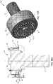
FIG. 7 is an isometric orthogonal view of a hydraulic MJT according to a preferred embodiment of the present invention. -
FIG. 8 is a top plan view of the hydraulic MJT ofFIG. 7 . -
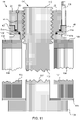
FIG. 9 is a cross sectional view through the line A-A indicated inFIG. 8 . -
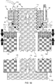
FIGS. 10-15 illustrate the step by step use of the hydraulic MJT ofFIG. 7 to fasten two workpieces together. -
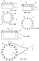
FIGS. 15A-15F illustrate the step by step use of the hydraulic MJT ofFIG. 7 to close a vessel having a flanged opening. -
FIGS. 16A and 16B illustrate a bolt-style hydraulic compression tool according to an embodiment of the present invention. -
FIGS. 17A-17C illustrate a nut-style hydraulic compression tool with locking ring, according to an embodiment of the present invention. -
FIGS. 18A and 18B illustrate a bolt-style hydraulic compression tool similar to the tool ofFIGS. 17A-17C . -
FIGS. 19A-19C illustrate a nut-style hydraulic compression tool with locking shims, according to an embodiment of the present invention. -
FIGS. 20A and 20B illustrate a bolt-style hydraulic compression tool similar to the tool ofFIGS. 19A-19C . -
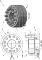
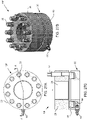
FIGS. 21A-21C illustrate nut-style hydraulic compression tools with load cell, according to embodiments of the present invention. -
FIGS. 24A-26B illustrate bolt-style hydraulic compression tools similar to the tools ofFIGS. 21A-21C . -
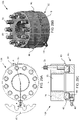
FIGS. 27A-29B illustrate nut-style hydraulic compression tools with a further load cell according to embodiments of the present invention. -
FIGS. 30A-32B illustrate bolt-style hydraulic compression tools similar to the tools ofFIGS. 27A-29C . -
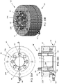
FIGS. 33A-33C illustrate a further nut-style hydraulic compression tool according to an embodiment of the present invention. -
FIGS. 34A-34B illustrate a bolt-style hydraulic compression tool similar to the tool ofFIGS. 33A-33C . - Referring to
FIG. 7 , there is illustrated in isometric view aMJT 10 according to a first embodiment of the present invention which will be referred to herein as a "hydraulic MJT".FIG. 8 is a plan view of thehydraulic MJT 10 whereasFIG. 9 is a I a plan view through the section A-A as indicated inFIG. 8 . - The
hydraulic MJT 10 according to this embodiment of the invention is in the form of a nut and generally comprises anannular body 20 with central axis "L" having a concentric circular threadedhole 25 formed therethrough to receive a stud or bolt (not shown). Theannular body 20 is formed with a concentric polar array of threaded jack bolt holes therethrough in similar fashions toholes 201 as illustrated inFIG. 1 . Through each of the threaded jack bolt holes there passes a corresponding one of a plurality ofjack bolts 30a,...,30n (which may be generally referred to herein as simply "30" for brevity). Thebody 20 sits upon apiston 40 which in the present embodiment comprises a load bearing member in that in use it applies force to a workpiece to be fastened, such as a pipe flange for example. In some situations the piston may apply the force to the workpiece via an intermediate member such as a washer. With reference toFIG. 9 , thebody 20 and thepiston 40 are shaped so that they cooperate to define anannular pressure chamber 50 therebetween. Thepressure chamber 50 is in fluid communication via afluid passage 65 with ahydraulic port 60. Theport 60 may be positioned on the top outer periphery of thebody 20 adjacent or proximate to at least one of thejack bolts 30. - The operation of the
hydraulic MJT 10 will now be described with reference toFIGS. 10 to 15 .FIG. 10 is a cross sectional side view of abolt 100 with ashank 103 penetrating first and second workpieces in the form of first and second flanges 102,104 that are to be fastened together. A bearing surface of thehead 106 of the bolt abuts awasher 108 in this example. Thewasher 108 in turn abuts the outside of thesecond flange 104. Thepoint 110 of the bolt and much of the thread length of theshank 102 extends out through thesecond flange 102 for capture by thehydraulic MJT 10 as will be explained. - Referring now to
FIG. 11 , thehydraulic MJT 10 is installed ontobolt 106 by threading thebody 20 onto thebolt 100 until the load bearing member in the form ofpiston 40 seats against the upper, outer, side of thefirst flange 102. Annularhydraulic seals pressure chamber 50. Although not shown, such seals are also present in the embodiments that are described with reference toFIGS. 16A onwards. - Returning to
FIG.11 , thejack bolts 30 are sufficiently withdrawn so that they do not abut the upper side of thepiston 40 and so at this time they exert no force against the piston. In this position thepiston 40 and thebody 20 are brought close together so that thepressure chamber 50, which is visible inFIG. 9 for example, is vastly reduced in volume. - Subsequently, as shown in
FIG. 12 ahydraulic line 111 is applied to thehydraulic port 60 using a suitable hydraulic nipple and coupler. Thehydraulic line 111 is coupled to a source of hydraulic power.FIG. 13 illustrates how upon applying hydraulic pressure via theline 111 thehydraulic chamber 50 fills with hydraulic fluid thereby forcing thepiston 40 apart from thebody 20 to a separation distance "D" thereby tensioning the bolt as indicated byarrows piston 40, bears down upon the outside, i.e. the topside as shown inFIG. 13 , of thefirst flange 102. - The separation of the
body 20 and thepiston 40 results in the generation of an axial load when thehydraulic MJT 10 is mounted to thebolt 100 and thepressure chamber 50 receives hydraulic fluid. The tensioning of thebolt 100 results in compression and/or tightening of the work pieces,e.g. flanges FIG. 13 , this means that the first andsecond flanges arrows flanges MJT 10 may be hydraulically operated simultaneously and from the same source of hydraulic power thereby ensuring uniform, simultaneous joint closure. - Referring now to
FIG. 14 , whilst application of the hydraulic pressure continues, thejack bolts 30a,...,30n are each rotated sufficiently to bring their points firmly against the load bearing member, which in the present embodiment comprisespiston 40. It is not essential to perform this step on thejack bolts 30 in any particular order because evenly distributed loading between the body and the piston has already been achieved by virtue of the application of the hydraulic pressure. -
FIG. 15 illustrates a subsequent stage in which thehydraulic line 111 has been removed. Thejack bolts 30 are now torqued, for example with a torque wrench, as indicated byarrow 113 thereby causing the distance between thepiston 40 and thebody 20 to increase slightly further to D+ΔD as shown inFIG. 15 thereby applying a precise final preload to thebolt 100. -
FIGS. 15A to 15F illustrate the use of a plurality of thehydraulic MJTs 10 to fasten acover 102 over anopening 120 of avessel 117.FIGs. 15A, 15C and 14E comprise top plan views whereasFIGs. 15B, 15D and 15F comprise corresponding top plan views. As may be seen inFIGS. 15A and 15B ,vessel 117 is formed with aflange 104 about opening 120. A plurality ofstuds 109 are disposed in a polar array around theflange 104 and stand proud therefrom. Thecover 102 is formed with holes therethrough corresponding to thestuds 109. As shown inFIGS. 15C and 15D acover 102, formed with peripheral holes corresponding tostuds 109 is placed overflange 104 so that thestuds 109 extend through the holes as may be seen inFIG 15C .Hydraulic MJTs 10, of the type previously illustrated inFIG 7 for example are threaded onto each of thestuds 109 until hand tight. Hydraulic lines are then attached toinlets 60 of theMJTs 10 in order to convey hydraulic pressure fromhydraulic pressure source 119. All or a number of theMJTs 10 may be hydraulically tensioned at once however it is preferable that the MJTs being tensioned are angularly spaced from each other, for example at 120 degrees as shown in the example ofFIG. 15F . Once hydraulically tensioned the jackbolts of theMJTs 10 can then be manually torqued. - Referring now to
FIGS. 16A, 16B , in a further embodiment of the invention a hydraulic MJT 10' is provided in a bolt-style, rather than the nut-style of the previously discussedembodiment 10. The hydraulic MJT 10' illustrated inFIGS. 16A, 16B comprises abody 20 that is integrally formed with a threadedshaft 27. A plurality ofjack bolts 30 are threadedly received through thebody 20. Each of the plurality ofjack bolts 30 is spaced uniformly from a longitudinal central axis L at spaced apart locations about an outer periphery thereof. A load bearing member in the form ofpiston 40 is located beneath the body and around the threadedshaft 27. Thebody 20 and thepiston 40 define apressure chamber 50 therebetween to receive hydraulic fluid from aport 60 via afluid passage 65. In use the threadedshaft 27 extends through afirst workpiece 102 and is captured by a threaded hole in asecond workpiece 104. In response to the application of hydraulic pressure via theport 60 to thepressure chamber 50 thebody 20 andpiston 40 axially separate, i.e. they displace relative to each other so that the load bearing member in the form ofpiston 40 bears down on thefirst workpiece 102 to be joined, and so stretches the shaft and generates an axial load indicated byarrows shaft 27 is threaded into the hole of thesecond work piece 104. The axial load acts to compress the work pieces being joined as indicated byarrows port 60 may be positioned on the top outer periphery of thebody 20 adjacent or proximate to at least one of thejack bolts 30. - Reference will now be made to
FIGS. 17A, 17B and 17C which depict a further nut-stylehydraulic MJT fastener 10A andFIGS. 18A, 18B which illustrate a corresponding bolt-style embodiment of ahydraulic MJT fastener 10A'. In these embodiments thehydraulic MJTs upper locking collar 70. Agap 75 is created between thebody 20 and lockingcollar 70 when thepressure chamber 50 receives hydraulic fluid to generate the pre-load. Thebody 20 has an outside thread to threadingly engage thelocking collar 70. Upon application of hydraulic pressure thepiston 40, which in this embodiment comprises the load bearing member against the workpiece to be joined, and thebody 20 move apart. The, lockingcollar 70 is then tightened and the hydraulic pressure may be released to transfer the pre-load to thelocking collar 70. Thejack bolts 30 are then tightened to further tension the elongate fastener,e.g. shaft 27 or a bolt or stud threadedly received into the axial recess, i.e.central hole 25. Accordingly, the hydraulic pressure may be removed as soon as the locking collar has been tightened and prior to tightening thejackbolts 30. - Referring to
FIGS. 19A to 19C and20A, 20B , in further embodiments, respectively nut-style MJT 10B andbolt style MJT 10B' are provided wherein thehydraulic compression tool 10 includes at least oneshim 80. Ashim gap 75 is created between thebody 20 andpiston 40 when thepressure chamber 50 receives hydraulic fluid to generate the pre-load. As shown inFIGS. 19A to 20B , fourshims 80 may be used to completely fill theshim gap 75. Theshims 80 are shaped to accommodate thejack bolts 30 extending through thebody 20. Theshims 80 in this example are formed with C-shapedindents 85 having diameters related to the diameter of thejack bolt 30 associated with theindent 85. -
FIGS. 21A-21B ,FIGS. 22A-22C andFIGS. 23A-23C illustratefurther embodiments FIGS. 24A, 24B ;25A, 25B ;26A, 26B illustrate correspondingbolt style MJTs 10C', 10D' and 10E' respectively. In these embodiments aload cell 90 may be incorporated as shown. The load cell comprises the load bearing member that bears upon a workpiece to be fastened in use. Thehydraulic MJTs annular body 20 having aannular recess 25 to receive a stud (not shown), and a plurality ofjack bolts 30 spaced uniformly from a longitudinal central axis L at spaced apart locations about an outer periphery thereof. At least onepiston 40 is slidingly received into theload cell 90 to define apressure chamber 50 therebetween to receive hydraulic fluid through aport 60 and afluid passage 65, wherein thebody 20 andload cell 90 axially separate to generate an axial load when thetool 10 is mounted to the stud and thepressure chamber 50 receives hydraulic fluid, and wherein theport 60 is positioned on the side outer periphery of theload cell 90 along a plane perpendicular to the longitudinal central axis L that does not intersect anyjack bolt 30. TheMJT 10D includes a lockingring 70 for holding thebody 20 from theload cell 90 subsequent to hydraulic pressure being removed and prior to torqueing of thejackbolts 30 whereas theMJT 10E makes use ofshims 80 for a similar purpose. TheMJTs 10C', 10D' and 10E' are bolt-style embodiments and so an elongate fastener in the form ofshaft 27 is integrally formed with thebody 20. In operation the axial load compresses the work pieces being joined. In theembodiments 10C to 10E'piston 40 engages a bottom face of thebody 20 and in these embodiments the support surface is provided by the underside of theload cell 90 which acts as the load bearing member against a workpiece to be fastened. -
Nut style MJTs FIGS. 27A-C ;28A-C and29A-C respectively. In these embodiments of the invention anannular piston 40 is located betweenbody 20 andload cell 90. Thepiston 40 cooperates with theload cell 90 to define ahydraulic chamber 40. The points ofjackbolts 30 are torqued onto the upper surface of thepiston 40 in use. - A locking
nut 90 is provided in the case ofMJT 10G whereasshims 80 are provided in the case ofMJT 10H. In both cases the lockingnut 90 and shims 10 are provided to maintain the distance between thebody 20 and theload cell 90 subsequent to removal of hydraulic pressure and prior to torqueing of thejackbolts 30. -
Bolt style MJTs 10F', 10G', and 10H', are illustrated inFIGs. 30A, 30B ;31A, 31B and32A, 32B respectively which correspond to thenut style MJTs -
FIGS. 33A-33C depict a further embodiment of a nut-style hydrauliccompression tool MJT 101 according to an embodiment of the present invention.MJT 101 has a two-partannular body 20 with a first inner part 20a having anannular recess 25 to receive a stud (not shown), and a plurality ofjack bolts 30 spaced uniformly from a longitudinal central axis L at spaced apart locations about its outer periphery. Asecond part 20B of the two-partannular body 20 is threaded about the outside of thefirst part 20A. Aload cell 90 locates beneath theouter part 20B of thebody 20. Awasher 64 locates within theannular load cell 90 concentric with thefirst part 20A of theannular body 20. Theload cell 90 is comprised of at least onepiston 40 slidingly received into theload cell 90 to define apressure chamber 50 therebetween to receive hydraulic fluid through aport 60 and afluid passage 65. Forcing hydraulic fluid intochamber 50 causes the outer part of thebody 20B and hence also theinner part 20A of the body to axially separate from theload cell 90 when thetool MJT 101 is mounted to the stud. Once theMJT 101 has been preloaded with hydraulic pressure thejackbolts 30 may be torqued thereby forcing thewasher 64 down onto a workpiece to be fastened. As shown inFIGS. 33A-33C , theport 60 may be positioned on the side outer periphery of theload cell 90 along a plane perpendicular to the longitudinal central axis L that intersects twojack bolts 30. The axial load may compress and/ or tighten the work pieces being joined. -
FIGS. 34A, 34B depict a nut-style MJT 10J corresponding to thebolt style embodiment 101 that has been discussed. - All numerical quantities stated herein are approximate, unless indicated otherwise, and are to be understood as being prefaced and modified in all instances by the term "about". The numerical quantities disclosed herein are to be understood as not being strictly limited to the exact numerical values recited. Instead, unless indicated otherwise, each numerical value included in this disclosure is intended to mean both the recited value and a functionally equivalent range surrounding that value.
- All numerical ranges recited herein include all sub-ranges subsumed therein. For example, a range of "1 to 10" is intended to include all sub-ranges between (and including) the recited minimum value of 1 and the recited maximum value of 10, that is, having a minimum value equal to or greater than 1 and a maximum value equal to or less than 10.
- As generally used herein, the articles "one", "a", "an", and "the" include "at least one" or "one or more" of what is claimed or described, unless indicated otherwise. For example, "a component" means one or more components, and thus, possibly, more than one component is contemplated and may be employed or used in an implementation of the described embodiments.
- As generally used herein, the terms "include", "includes", and "including" are meant to be non-limiting.
- As generally used herein, the terms "have", "has", and "having" are meant to be non-limiting.
- As generally used herein, the term "stud" means tension elongated members, such as bolts, studs, and rods that may or may not comprise an integral head and/or threads. The integral head and/or threads may be configured to apply compression forces across a joint to produce a tension load in the stud. The threads may be configured for threaded connection with the hydraulic compression tool.
- A person skilled in the art may appreciate that the hydraulic compression tool and components thereof may be made from any appropriate material and may have any size required for a particular application using materials and stress calculations known in the art. The body may comprise metal, such as steel, the pressure chamber may comprise a polymer, and the washer may comprise brass or aluminum.
- In one embodiment a hydraulic compression tool to compress work pieces being joined may generally comprise a body having a polar array of jack bolts spaced uniformly from a longitudinal central axis at spaced apart locations about an outer surface thereof, a piston slidingly received into the body to define a pressure chamber therebetween to receive hydraulic fluid through a port and a fluid passage, wherein the body and piston axially separate when the pressure chamber receives hydraulic fluid. The body may comprise an annular recess for receiving a stud. The annular recess may comprise threads formed on its inside surface for threaded engagement with the stud. The annular recess may lack threads on its inside surface for engagement with the stud by compression fit. The body may comprise a threaded shaft to engage a hole, such as a threaded hole and a blind hole, in the work piece(s).
- The body may comprise drilled and tapped holes to threadedly engage each jack bolt. The jack bolt may comprise a socket-head cap screw. A person having ordinary skill in the art may appreciate that the number of jack bolts may be selected according to the desired stress that is to be imposed on the shank portion of the fastener. The jack bolts may be arranged in only one annular array but two or more annular arrays may be used to accommodate the desired number of jack bolts. For example, the tool may comprise twenty-four jack bolts with twelve jack bolts spaced about each of the bolt centers in an alternating arrangement.
- The jack bolt may extend through a tapped hole and project from the body into engagement with a support surface. An end face of the jack bolt may extend into compressive engagement with a support surface. The support surface may comprise the piston, a load cell, or a washer. For example, the support surface may comprise a flange portion of the piston. The washer may be constructed from material having a hardness predetermined according to the forces required to support the tool. The washer may be made from sufficiently hard material, such as metal or plastic, so that the washer may sustain the load imposed thereon by the jack bolt without yielding under the imposed load. The washer may be made from a sufficiently soft material so that the end face of the jack bolt is not upset under the applied load.
- The jack bolts may be used to mechanically retain the axial load generated by the hydraulic pressure. The jack bolts may be torqued until the end surface firmly contacts the support surface. Each jack bolt may be rotated until the end face extends from the body to contact the support surface. The jack bolts may be torqued in a patterned sequence such as, for example, by torquing jacks bolts at opposite sides of the body and then advancing to an adjacent jack bolt. A lubricant, such as graphite, may be applied to the threads of the jack bolt to facilitate torquing thereof.
- The hydraulic compression tool may comprise a sealing device (not shown), such as a gasket, to substantially fluidly seal the pressure chamber so that hydraulic pressure may be generated. The sealing device may seal any gap between the body and piston. The pressure chamber may be defined by the body, the piston, fluid passage, and sealing device.
- The tool may comprise one or more ports. The port may be located on a top surface of the body or piston, such as adjacent or proximate to at least one of the jack bolts, or on a side surface of the body or piston. The port may comprise a standard threaded connection port to permit hydraulic fluid to be supplied to the pressure chamber at elevated pressure and vented therefrom. The port may comprise a one-way valve that threadedly engages the body and/ or fluid passage. The one-way valve may prevent or reduce backflow when the pressure source is disconnected from the port.
- The pressure source may comprise a high-pressure hand pump that is manually operated.
- The body may comprise an opening configured to allow the insertion of a threading tool, such as a tommy bar (not shown), to assist the tensioning of the work piece(s). The opening may be positioned on the top and/ or side outer periphery of the body.
- A locking collar or shim may be used to mechanically retain the axial load generated by the hydraulic pressure. The locking collar may be torqued while under hydraulic pressure until a face of the locking collar firmly contacts an opposing face of the body and/ or piston. The shim may be inserted in the gap between opposing faces of the body and piston that is generated by the hydraulic force. When the hydraulic pressure is released, the load is transferred onto the shims or locking collar to retain the load.
- The locking collar may comprise one of a lower collar type and an upper collar type. The hydraulic compression tool may comprise a lower locking collar including a piston having internal threads and external threads. The hydraulic compression tool may comprise an upper locking collar including a piston having internal threads and external threads. The external threads of the piston may engage mating threads of the locking collar. A gap between the body and locking collar may be created when the pressure chamber receives hydraulic fluid to generate the pre-load. The width of the gap may generally relate to the compression of the joint, gasket, if fitted, and the elongation of the stud. The locking collar may be tightened and the pressure may be released to transfer the pre-load to the locking collar.
- The hydraulic compression tool may comprise an upper locking collar including a plain bore load cell and a collar nut. The collar nut may comprise internal threads and external threads. The external threads may engage mating threads of the locking collar. A gap between the body and locking collar may be created when the pressure chamber receives hydraulic fluid to generate the pre-load. The width of the gap may generally relate to the compression of the joint, gasket, if fitted, and the elongation of the stud. The locking collar may be tightened and the pressure may be released to transfer the pre-load to the locking collar. The port may be positioned on the side of the piston because the load cell has a plain bore.
- The hydraulic compression tool may comprise a shim, and the piston may comprise a flanged piston. A shim gap may be created when the pressure chamber receives hydraulic fluid to generate the pre-load. The width of the gap may generally relate to the compression of the joint, gasket, if fitted, and the elongation of the stud. The width of the shim gap may be measured and a shim having the desired width may be inserted into the shim gap. The shim may comprise one or more shims such that the shims completely fill the shim gap. Each shim may be configured to couple to at least a portion of the jack bolts.
- A method of closing a vessel having a plurality of studs may generally comprise threading a hydraulic nut or hydraulic compression tool onto at least one of the plurality of studs of the vessel, and injecting hydraulic fluid into the chamber of the hydraulic nut and/or hydraulic compression tool to tension at least one stud. For example, the method may comprise threading a hydraulic compression tool onto three bolts of the vessel that are spaced 120 degrees apart, and injecting hydraulic fluid into the chamber of each of the or hydraulic compression tools to tension each of the three bolts. MJTs may be positioned adjacent to each of the hydraulic compression tools and tightened to the desired preload. Then, the plurality of jack bolts on each of the hydraulic compression tools may be tightened to the desired preload, and the hydraulic pressure may be released. Alternatively, the hydraulic pressure may be released and the hydraulic compression tools may be replaced by MJTs that are then tightened to the desired preload. The method may also include applying hydraulic compression tools to all of the studs and linking them with hoses to perofmr a single pass hydraulic closure.
- The method may comprise threading a hydraulic compression tool onto each of the bolts of the vessel, wherein each of the hydraulic compression tools are in fluid communication with each other, and injecting hydraulic fluid into the chamber of each of the hydraulic compression tools to tension each of the bolts substantially simultaneously to the same preload. The load generated by the hydraulic compression tools may be evenly distributed around the joint such that a compression gasket may flow into any surface irregularities of the vessel to provide an improved seal relative to tightening the bolts individually. When the desired preload is achieved, the plurality of jack bolts on each of the hydraulic compression tools may be tightened to the desired preload, and the hydraulic pressure may be released.
- The method may comprise torqueing the hydraulic compression tool onto a bolt of the vessel relatively low torque level prior to introducing hydraulic fluid to the port. For example, the hydraulic compression tool may be threaded onto the bolt until the hydraulic compression tool contacts the surface of the vessel. Then a hydraulic pumping unit may deliver hydraulic fluid, such as high-pressure oil, into the pressure chamber of the hydraulic compression tool. As the hydraulic pressure increases, the resulting axial force elongates the bolt, and thereby may compress the joint. When the desired preload is achieved, the pressure supply may be stopped to release the hydraulic pressure.
Claims (15)
- A multi jack tensioner (10, 10', 10A, 10A', 10B, 10B', 10C, 10C', 10D, 10D', 10E, 10E', 10F, 10F', 10G, 10G', 10H, 10H', 101, 10J) including:a body portion (20) formed to engage an elongate fastening member or integrally formed therewith;a load bearing member for applying force to a workpiece (102) to be fastened and arranged for location about said elongate fastening member adjacent the body portion (20);a pressure chamber (50) formed between the load bearing member and the body portion (20) arranged to displace the body portion (20) from the load bearing member in response to hydraulic pressure; anda plurality of jack bolts (30a-30n) extending between the body portion (20) and the load bearing member adapted to displace the body portion (20) from the load bearing member;wherein application of hydraulic pressure to the pressure chamber (50) displaces the body portion (20) from the load bearing member for tensioning said elongate fastening member and whereby subsequent tensioning of the elongate fastening member is applied by operation of the jack bolts (30a-30n),wherein the body portion (20) and load bearing member are shaped to cooperate and define the pressure chamber (50) therebetween, and wherein the plurality of jack bolts (30a-30n) extend through the body portion (20) to abut the loading bearing member.
- The multi jack tensioner (10, 10A, 10B, 10C, 10D, 10E, 10F, 10G, 10H, 101) of claim 1, wherein the body portion (20) is formed with an axial recess to threadedly engage the elongate fastening member wherein the elongate fastening member comprises a bolt (100) or stud.
- The multi jack tensioner (10', 10A', 10B', 10C', 10D', 10E', 10F', 10G', 10H', 10J) of claim 1 wherein the body portion (20) is integrally formed with the elongate fastening member.
- The multi jack tensioner (10, 10', 10A, 10A', 10B, 10B', 10C, 10C', 10D, 10D', 10E, 10E', 10F, 10F', 10G, 10G', 10H, 10H', 101, 10J) of claim 1, wherein the load bearing member is formed as a piston (40) arranged to cooperate with the body portion (20).
- The multi jack tensioner (10A, 10A', 10B, 10B', 10C, 10C', 10D, 10D', 10E, 10E', 10F, 10F', 10G, 10G', 10H, 10H', 101, 10J) of claim 1, wherein the load bearing member is formed as a load cell (90) with which a piston (40) cooperates that forces the body portion (20) in use.
- The multi jack tensioner (10, 10', 10A, 10A', 10B, 10B', 10C, 10C', 10D, 10D', 10E, 10E', 10F, 10F', 10G, 10G', 10H, 10H', 101, 10J) of claim 1, wherein the plurality of jack bolts (30a-30n) comprises an annular array of jack bolts threadedly received through holes formed spaced uniformly from a longitudinal central axis of the body portion (20) at spaced apart locations about an outer surface thereof.
- The multi jack tensioner (10, 10', 10A, 10A', 10B, 10B', 10C, 10C', 10D, 10D', 10E, 10E', 10F, 10F', 10G, 10G', 10H, 10H', 101, 10J) of claim 1, wherein a piston (40) is slidingly received into the body portion (20), and a pressure chamber (50) between the body portion (20) and piston (40) to receive hydraulic fluid through a port and a fluid passage, wherein when the pressure chamber (50) receives hydraulic fluid, the body portion (20) and piston (40) axially separate.
- The multi jack tensioner (10, 10', 10A, 10A', 10B, 10B', 10C, 10C', 10D, 10D', 10E, 10E', 10F, 10F', 10G, 10G', 10H, 10H', 101, 10J) of claim 1, wherein each of the plurality of jack bolts (30a-30n) is in threaded engagement with the body portion (20) and projects from the body portion (20) into compressive engagement with the load bearing member.
- The multi jack tensioner (101, 10J) of claim 1, wherein the load bearing member comprises a piston (40), a load cell (90), and a washer (64).
- The multi jack tensioner (10A, 10A', 10B, 10B', 10C, 10C', 10D, 10D', 10E, 10E', 10F, 10F', 10G, 10G', 10H, 10H', 101, 10J) of claim 1, wherein the load bearing member comprises a load cell (90).
- The multi jack tensioner (101, 10J) of claim 1 wherein the loading bearing member comprises a washer (64).
- The multi jack tensioner (10A, 10A') of claim 1 comprising a locking collar (70) for maintaining a distance between the load bearing member and the body portion (20) subsequent to removal of the hydraulic pressure.
- The multi jack tensioner (10B, 10B') of claim 1 comprising at least one shim (80) for maintaining a distance between the load bearing member and the body portion (20) subsequent to removal of the hydraulic pressure.
- A method of closing a vessel having at least one stud, the method comprising:
threading a first hydraulic compression tool onto the at least one stud, wherein the hydraulic compression tool comprisesa body (20) having a threaded shaft, and a plurality of jack bolts (30a-30n) spaced uniformly from a longitudinal central axis at spaced apart locations about an outer periphery thereof,a piston (40) slidingly received into the body (20) to define a pressure chamber (50) therebetween to receive hydraulic fluid through a port and a fluid passage, andwherein the body (20) and piston (40) axially separate when the tool is mounted to the stud and the pressure chamber (50) receives hydraulic fluid; injecting hydraulic fluid into the pressure chamber (50) to tension the at least one stud; and torqueing the plurality of jack bolts (30a-30n) to close the vessel, wherein the plurality of jack bolts (30a-30n) extend through the body portion (20) to abut the loading bearing member. - The method of claim 14 comprising:threading a second hydraulic compression tool onto another of the at least one stud; andsimultaneously injecting hydraulic fluid into the pressure chamber of each of the hydraulic compression tools threaded onto the at least one shaft, wherein each of the pressure chambers are in fluid communication with the other to tension the at least one stud to substantially equal preloads.
Applications Claiming Priority (2)
| Application Number | Priority Date | Filing Date | Title |
|---|---|---|---|
| US201662350787P | 2016-06-16 | 2016-06-16 | |
| PCT/US2017/037834 WO2017218870A1 (en) | 2016-06-16 | 2017-06-16 | Improvements to multi-jack tensioners |
Publications (3)
| Publication Number | Publication Date |
|---|---|
| EP3471920A1 EP3471920A1 (en) | 2019-04-24 |
| EP3471920A4 EP3471920A4 (en) | 2020-03-04 |
| EP3471920B1 true EP3471920B1 (en) | 2023-01-11 |
Family
ID=60663820
Family Applications (1)
| Application Number | Title | Priority Date | Filing Date |
|---|---|---|---|
| EP17814153.7A Active EP3471920B1 (en) | 2016-06-16 | 2017-06-16 | Improvements to multi-jack tensioners |
Country Status (6)
| Country | Link |
|---|---|
| US (1) | US11292093B2 (en) |
| EP (1) | EP3471920B1 (en) |
| CN (1) | CN109476004A (en) |
| AU (1) | AU2017285427B2 (en) |
| DK (1) | DK3471920T3 (en) |
| WO (1) | WO2017218870A1 (en) |
Families Citing this family (9)
| Publication number | Priority date | Publication date | Assignee | Title |
|---|---|---|---|---|
| DE102019111237B4 (en) | 2019-02-18 | 2020-11-19 | Dietmar Schnier | Two-part screw nut with high pressing force |
| WO2021108852A1 (en) * | 2019-12-02 | 2021-06-10 | Nord-Lock Switzerland Gmbh | Method and apparatus for retaining tension in a bolt or stud |
| EP4126459A1 (en) | 2020-03-25 | 2023-02-08 | Milwaukee Electric Tool Corporation | Bolt tensioning tool |
| US12044264B2 (en) * | 2020-07-21 | 2024-07-23 | Nord-Lock Switzerland Gmbh | Method and apparatus for fastening in a high fluid pressure environment |
| CN112196910A (en) * | 2020-10-09 | 2021-01-08 | 国网黑龙江省电力有限公司牡丹江水力发电总厂 | Auxiliary assembly device and method for turbine shaft flange and generator shaft flange |
| CN112682104B (en) * | 2020-12-25 | 2022-11-18 | 福建福清核电有限公司 | Bolt installation method for steam turbine coupling in nuclear power plant |
| CN114876935B (en) * | 2022-04-27 | 2024-04-26 | 中国舰船研究设计中心 | Internal and external balanced hydraulic nut for installing ship propeller and installation method thereof |
| USD1015863S1 (en) | 2022-05-20 | 2024-02-27 | Nord-Lock Switzerland Gmbh | Fastening device |
| JP7496857B2 (en) * | 2022-07-28 | 2024-06-07 | 三菱重工業株式会社 | How to adjust the amount of elongation of bolt components |
Citations (1)
| Publication number | Priority date | Publication date | Assignee | Title |
|---|---|---|---|---|
| DE102014219643A1 (en) * | 2014-05-12 | 2015-11-12 | Siemens Aktiengesellschaft | Annular clamping nut for a tie rod |
Family Cites Families (41)
| Publication number | Priority date | Publication date | Assignee | Title |
|---|---|---|---|---|
| US3154006A (en) * | 1962-10-12 | 1964-10-27 | Danly Mach Specialties Inc | Tensioning system for power press tie rods |
| US3285568A (en) * | 1965-03-17 | 1966-11-15 | Biach Ind | Tensioning apparatus |
| GB1115457A (en) * | 1965-11-08 | 1968-05-29 | P & O Res & Dev Co | Improvements in propeller fastening |
| US3424080A (en) * | 1967-08-23 | 1969-01-28 | Lambros A Pappas | Hydraulic tie rod nut |
| DK119906B (en) * | 1968-12-10 | 1971-03-08 | Burmeister & Wains Mot Mask | Hydraulic tightening mechanism for a bolt. |
| US3722332A (en) * | 1971-06-01 | 1973-03-27 | Transfer Systems | Apparatus for securing the bolts of the reactor pressure vessel head to the reactor pressure vessel |
| FR2412384A1 (en) * | 1977-12-23 | 1979-07-20 | Kloeckner Werke Ag | HYDRAULIC CLAMPING DEVICE |
| US4338037A (en) * | 1980-08-08 | 1982-07-06 | The Yorde Machine Products Company | Multiple jackscrew rod to crosshead mounting |
| US4569506A (en) * | 1984-02-08 | 1986-02-11 | Automation Industries, Inc. | Self-contained stud tensioner and tightener device |
| US4622730A (en) * | 1984-03-30 | 1986-11-18 | Rolf Steinbock | Apparatus to mechanically stress a bolt-type fastener |
| USRE33490E (en) | 1984-03-30 | 1990-12-18 | Apparatus to mechanically stress a bolt-type fastener | |
| WO1986005135A1 (en) * | 1985-03-06 | 1986-09-12 | Pilgrim Engineering Developments Limited | Improvements in multi-stud tensioners |
| US4854798A (en) * | 1987-05-29 | 1989-08-08 | Westinghouse Electric Corp. | In-place tensioning washer |
| US5046906A (en) * | 1987-09-29 | 1991-09-10 | Bucknell John W | Force applicators |
| US4846444A (en) * | 1988-07-05 | 1989-07-11 | Michael Vassalotti | Stud tensioning and tighetning apparatus |
| US4927305A (en) | 1988-09-02 | 1990-05-22 | Peterson Charles D | Tightening device for threaded connectors |
| US5013199A (en) * | 1989-12-18 | 1991-05-07 | Allied-Signal Inc. | Stripline launcher spring washer |
| US5075950A (en) | 1990-06-28 | 1991-12-31 | Steinbock Rolf H | Method for loosening jack bolts |
| US5083889A (en) | 1990-10-04 | 1992-01-28 | Steinbock Rolf H | Structure for preventing escape of jack bolts in apparatus to mechanically stress a bolt-type fastener |
| GB2274893B (en) * | 1993-02-05 | 1995-10-04 | Hydra Tight Ltd | Tensioning arrangement |
| DE4313778A1 (en) * | 1993-04-27 | 1994-11-03 | Westfalia Becorit Ind Tech | Screw clamping device |
| JPH0839452A (en) | 1994-07-27 | 1996-02-13 | Kotobuki Sangyo Kk | Bolt tightening device |
| US5846042A (en) * | 1997-06-24 | 1998-12-08 | Sony Corporation | Fastener/shaft locking and adjustment apparatus |
| US6112396A (en) | 1998-06-10 | 2000-09-05 | Steinbock Machinery Co. | Jackbolts for multi jackbolt tensioners |
| DE69937246T2 (en) * | 1998-06-10 | 2008-07-03 | Steinbock Machinery Co. | DISCIPLE SCREWS FOR SPANNER WITH SEVERAL DISPENSER SCREWS |
| EP1448338B1 (en) * | 2001-11-30 | 2009-12-23 | Westinghouse Electric Company LLC | Method of closing a pressure vessel |
| US7008156B2 (en) | 2002-03-26 | 2006-03-07 | Atushi Imai | Load transfer apparatus |
| US6938450B1 (en) * | 2003-02-07 | 2005-09-06 | Dana Corporation | Double nut tensioner assembly for pre-stretched tie rods |
| US20080279625A1 (en) * | 2004-02-25 | 2008-11-13 | John Wentworth Bucknell | Hydraulically Assisted Fasteners |
| KR101205990B1 (en) * | 2004-06-17 | 2012-11-29 | 존 웬트워드 버크넬 | Bolt tensioning apparatus and method thereof |
| JP4839317B2 (en) * | 2005-10-05 | 2011-12-21 | 淳 今井 | Liquid pressure device |
| US7637706B2 (en) * | 2007-08-21 | 2009-12-29 | Steinbock Machinery Corproation | Pre-stressing apparatus using a split threaded fastener |
| US8739697B1 (en) | 2009-10-29 | 2014-06-03 | Us Synthetic Corporation | High pressure press with tensioning assembly and related methods |
| MX2010002060A (en) * | 2010-02-22 | 2011-08-30 | Luis Gerardo Oyervides Ochoa | Hydraulic nut with calibration device and warning alarm. |
| US9188146B1 (en) * | 2010-08-05 | 2015-11-17 | Riverhawk Company | Hydraulic rod tensioning system |
| GB201121976D0 (en) * | 2011-12-20 | 2012-02-01 | Ceney David | Stud tensioning apparatus |
| US9879706B2 (en) * | 2012-03-06 | 2018-01-30 | Technofast Industries Pty Ltd | High-capacity radial fit coupling bolts |
| DE102012109681A1 (en) * | 2012-10-11 | 2014-04-17 | Jörg Hohmann | Clamping device for stretching a threaded bolt |
| US9216495B2 (en) * | 2013-07-09 | 2015-12-22 | General Electric Company | Spacer |
| FR3034821B1 (en) * | 2015-04-09 | 2017-09-08 | Skf Ab | VOLTAGE DEVICE FOR PRE-STRESSING AN ASSEMBLY USING A THREADED ROD |
| EP3093641B1 (en) * | 2015-05-11 | 2017-06-28 | Siemens Aktiengesellschaft | Method for determining the axial tensile force introduced into a component |
-
2017
- 2017-06-16 EP EP17814153.7A patent/EP3471920B1/en active Active
- 2017-06-16 AU AU2017285427A patent/AU2017285427B2/en not_active Ceased
- 2017-06-16 CN CN201780043908.2A patent/CN109476004A/en active Pending
- 2017-06-16 US US16/310,528 patent/US11292093B2/en active Active
- 2017-06-16 DK DK17814153.7T patent/DK3471920T3/en active
- 2017-06-16 WO PCT/US2017/037834 patent/WO2017218870A1/en not_active Ceased
Patent Citations (1)
| Publication number | Priority date | Publication date | Assignee | Title |
|---|---|---|---|---|
| DE102014219643A1 (en) * | 2014-05-12 | 2015-11-12 | Siemens Aktiengesellschaft | Annular clamping nut for a tie rod |
Also Published As
| Publication number | Publication date |
|---|---|
| WO2017218870A1 (en) | 2017-12-21 |
| US11292093B2 (en) | 2022-04-05 |
| EP3471920A1 (en) | 2019-04-24 |
| AU2017285427A1 (en) | 2019-01-03 |
| CA3028270A1 (en) | 2017-12-21 |
| AU2017285427B2 (en) | 2022-08-11 |
| CN109476004A (en) | 2019-03-15 |
| EP3471920A4 (en) | 2020-03-04 |
| DK3471920T3 (en) | 2023-04-03 |
| US20190321927A1 (en) | 2019-10-24 |
Similar Documents
| Publication | Publication Date | Title |
|---|---|---|
| US11292093B2 (en) | Multi-jack tensioners | |
| US11285573B2 (en) | Multiple chamber hydraulic multi-jack bolt tensioners | |
| US12286969B2 (en) | Fluid end assembly | |
| AU2017206268B2 (en) | A Tensioning Apparatus | |
| EP1979630B1 (en) | Unibody hydraulic nut | |
| US10195700B1 (en) | High pressure press with tensioning assembly and related methods | |
| CN104487719A (en) | Screw loosening prevention structure | |
| JP2025157571A (en) | Fastening method and device for high fluid pressure environments | |
| CA3028270C (en) | Improvements to multi-jack bolt tensioners | |
| CN215285052U (en) | Quick erection equipment of track | |
| CN113511278A (en) | Track quick installation equipment | |
| US12350774B2 (en) | Method and apparatus for fastening in a high fluid pressure environment |
Legal Events
| Date | Code | Title | Description |
|---|---|---|---|
| STAA | Information on the status of an ep patent application or granted ep patent |
Free format text: STATUS: THE INTERNATIONAL PUBLICATION HAS BEEN MADE |
|
| PUAI | Public reference made under article 153(3) epc to a published international application that has entered the european phase |
Free format text: ORIGINAL CODE: 0009012 |
|
| STAA | Information on the status of an ep patent application or granted ep patent |
Free format text: STATUS: REQUEST FOR EXAMINATION WAS MADE |
|
| 17P | Request for examination filed |
Effective date: 20190115 |
|
| AK | Designated contracting states |
Kind code of ref document: A1 Designated state(s): AL AT BE BG CH CY CZ DE DK EE ES FI FR GB GR HR HU IE IS IT LI LT LU LV MC MK MT NL NO PL PT RO RS SE SI SK SM TR |
|
| AX | Request for extension of the european patent |
Extension state: BA ME |
|
| DAV | Request for validation of the european patent (deleted) | ||
| DAX | Request for extension of the european patent (deleted) | ||
| A4 | Supplementary search report drawn up and despatched |
Effective date: 20200204 |
|
| RIC1 | Information provided on ipc code assigned before grant |
Ipc: F16B 31/04 20060101ALI20200129BHEP Ipc: F16D 1/033 20060101ALI20200129BHEP Ipc: B25B 29/02 20060101AFI20200129BHEP Ipc: G21C 13/06 20060101ALI20200129BHEP Ipc: B23P 19/06 20060101ALI20200129BHEP |
|
| RIN1 | Information on inventor provided before grant (corrected) |
Inventor name: LUTTY, ADAM GLENN Inventor name: MYERS, WILLIAM Inventor name: GREENWELL, STEVEN |
|
| RIN1 | Information on inventor provided before grant (corrected) |
Inventor name: GREENWELL, STEVEN Inventor name: MYERS, WILLIAM Inventor name: LUTTY, ADAM GLENN |
|
| RIN1 | Information on inventor provided before grant (corrected) |
Inventor name: MYERS, WILLIAM Inventor name: LUTTY, ADAM GLENN Inventor name: GREENWELL, STEVEN |
|
| STAA | Information on the status of an ep patent application or granted ep patent |
Free format text: STATUS: EXAMINATION IS IN PROGRESS |
|
| 17Q | First examination report despatched |
Effective date: 20211221 |
|
| GRAP | Despatch of communication of intention to grant a patent |
Free format text: ORIGINAL CODE: EPIDOSNIGR1 |
|
| STAA | Information on the status of an ep patent application or granted ep patent |
Free format text: STATUS: GRANT OF PATENT IS INTENDED |
|
| INTG | Intention to grant announced |
Effective date: 20220812 |
|
| GRAS | Grant fee paid |
Free format text: ORIGINAL CODE: EPIDOSNIGR3 |
|
| GRAA | (expected) grant |
Free format text: ORIGINAL CODE: 0009210 |
|
| STAA | Information on the status of an ep patent application or granted ep patent |
Free format text: STATUS: THE PATENT HAS BEEN GRANTED |
|
| AK | Designated contracting states |
Kind code of ref document: B1 Designated state(s): AL AT BE BG CH CY CZ DE DK EE ES FI FR GB GR HR HU IE IS IT LI LT LU LV MC MK MT NL NO PL PT RO RS SE SI SK SM TR |
|
| REG | Reference to a national code |
Ref country code: GB Ref legal event code: FG4D |
|
| REG | Reference to a national code |
Ref country code: CH Ref legal event code: EP |
|
| REG | Reference to a national code |
Ref country code: DE Ref legal event code: R096 Ref document number: 602017065449 Country of ref document: DE |
|
| REG | Reference to a national code |
Ref country code: IE Ref legal event code: FG4D |
|
| REG | Reference to a national code |
Ref country code: AT Ref legal event code: REF Ref document number: 1543126 Country of ref document: AT Kind code of ref document: T Effective date: 20230215 |
|
| REG | Reference to a national code |
Ref country code: DK Ref legal event code: T3 Effective date: 20230329 |
|
| REG | Reference to a national code |
Ref country code: LT Ref legal event code: MG9D |
|
| REG | Reference to a national code |
Ref country code: NL Ref legal event code: MP Effective date: 20230111 |
|
| P01 | Opt-out of the competence of the unified patent court (upc) registered |
Effective date: 20230524 |
|
| PG25 | Lapsed in a contracting state [announced via postgrant information from national office to epo] |
Ref country code: NL Free format text: LAPSE BECAUSE OF FAILURE TO SUBMIT A TRANSLATION OF THE DESCRIPTION OR TO PAY THE FEE WITHIN THE PRESCRIBED TIME-LIMIT Effective date: 20230111 |
|
| PG25 | Lapsed in a contracting state [announced via postgrant information from national office to epo] |
Ref country code: RS Free format text: LAPSE BECAUSE OF FAILURE TO SUBMIT A TRANSLATION OF THE DESCRIPTION OR TO PAY THE FEE WITHIN THE PRESCRIBED TIME-LIMIT Effective date: 20230111 Ref country code: PT Free format text: LAPSE BECAUSE OF FAILURE TO SUBMIT A TRANSLATION OF THE DESCRIPTION OR TO PAY THE FEE WITHIN THE PRESCRIBED TIME-LIMIT Effective date: 20230511 Ref country code: NO Free format text: LAPSE BECAUSE OF FAILURE TO SUBMIT A TRANSLATION OF THE DESCRIPTION OR TO PAY THE FEE WITHIN THE PRESCRIBED TIME-LIMIT Effective date: 20230411 Ref country code: LV Free format text: LAPSE BECAUSE OF FAILURE TO SUBMIT A TRANSLATION OF THE DESCRIPTION OR TO PAY THE FEE WITHIN THE PRESCRIBED TIME-LIMIT Effective date: 20230111 Ref country code: LT Free format text: LAPSE BECAUSE OF FAILURE TO SUBMIT A TRANSLATION OF THE DESCRIPTION OR TO PAY THE FEE WITHIN THE PRESCRIBED TIME-LIMIT Effective date: 20230111 Ref country code: HR Free format text: LAPSE BECAUSE OF FAILURE TO SUBMIT A TRANSLATION OF THE DESCRIPTION OR TO PAY THE FEE WITHIN THE PRESCRIBED TIME-LIMIT Effective date: 20230111 Ref country code: ES Free format text: LAPSE BECAUSE OF FAILURE TO SUBMIT A TRANSLATION OF THE DESCRIPTION OR TO PAY THE FEE WITHIN THE PRESCRIBED TIME-LIMIT Effective date: 20230111 |
|
| PG25 | Lapsed in a contracting state [announced via postgrant information from national office to epo] |
Ref country code: SE Free format text: LAPSE BECAUSE OF FAILURE TO SUBMIT A TRANSLATION OF THE DESCRIPTION OR TO PAY THE FEE WITHIN THE PRESCRIBED TIME-LIMIT Effective date: 20230111 Ref country code: PL Free format text: LAPSE BECAUSE OF FAILURE TO SUBMIT A TRANSLATION OF THE DESCRIPTION OR TO PAY THE FEE WITHIN THE PRESCRIBED TIME-LIMIT Effective date: 20230111 Ref country code: IS Free format text: LAPSE BECAUSE OF FAILURE TO SUBMIT A TRANSLATION OF THE DESCRIPTION OR TO PAY THE FEE WITHIN THE PRESCRIBED TIME-LIMIT Effective date: 20230511 Ref country code: GR Free format text: LAPSE BECAUSE OF FAILURE TO SUBMIT A TRANSLATION OF THE DESCRIPTION OR TO PAY THE FEE WITHIN THE PRESCRIBED TIME-LIMIT Effective date: 20230412 Ref country code: FI Free format text: LAPSE BECAUSE OF FAILURE TO SUBMIT A TRANSLATION OF THE DESCRIPTION OR TO PAY THE FEE WITHIN THE PRESCRIBED TIME-LIMIT Effective date: 20230111 |
|
| REG | Reference to a national code |
Ref country code: DE Ref legal event code: R097 Ref document number: 602017065449 Country of ref document: DE |
|
| PG25 | Lapsed in a contracting state [announced via postgrant information from national office to epo] |
Ref country code: SM Free format text: LAPSE BECAUSE OF FAILURE TO SUBMIT A TRANSLATION OF THE DESCRIPTION OR TO PAY THE FEE WITHIN THE PRESCRIBED TIME-LIMIT Effective date: 20230111 Ref country code: RO Free format text: LAPSE BECAUSE OF FAILURE TO SUBMIT A TRANSLATION OF THE DESCRIPTION OR TO PAY THE FEE WITHIN THE PRESCRIBED TIME-LIMIT Effective date: 20230111 Ref country code: EE Free format text: LAPSE BECAUSE OF FAILURE TO SUBMIT A TRANSLATION OF THE DESCRIPTION OR TO PAY THE FEE WITHIN THE PRESCRIBED TIME-LIMIT Effective date: 20230111 Ref country code: CZ Free format text: LAPSE BECAUSE OF FAILURE TO SUBMIT A TRANSLATION OF THE DESCRIPTION OR TO PAY THE FEE WITHIN THE PRESCRIBED TIME-LIMIT Effective date: 20230111 |
|
| PLBE | No opposition filed within time limit |
Free format text: ORIGINAL CODE: 0009261 |
|
| STAA | Information on the status of an ep patent application or granted ep patent |
Free format text: STATUS: NO OPPOSITION FILED WITHIN TIME LIMIT |
|
| PG25 | Lapsed in a contracting state [announced via postgrant information from national office to epo] |
Ref country code: SK Free format text: LAPSE BECAUSE OF FAILURE TO SUBMIT A TRANSLATION OF THE DESCRIPTION OR TO PAY THE FEE WITHIN THE PRESCRIBED TIME-LIMIT Effective date: 20230111 |
|
| 26N | No opposition filed |
Effective date: 20231012 |
|
| PG25 | Lapsed in a contracting state [announced via postgrant information from national office to epo] |
Ref country code: MC Free format text: LAPSE BECAUSE OF FAILURE TO SUBMIT A TRANSLATION OF THE DESCRIPTION OR TO PAY THE FEE WITHIN THE PRESCRIBED TIME-LIMIT Effective date: 20230111 |
|
| PG25 | Lapsed in a contracting state [announced via postgrant information from national office to epo] |
Ref country code: SI Free format text: LAPSE BECAUSE OF FAILURE TO SUBMIT A TRANSLATION OF THE DESCRIPTION OR TO PAY THE FEE WITHIN THE PRESCRIBED TIME-LIMIT Effective date: 20230111 Ref country code: MC Free format text: LAPSE BECAUSE OF FAILURE TO SUBMIT A TRANSLATION OF THE DESCRIPTION OR TO PAY THE FEE WITHIN THE PRESCRIBED TIME-LIMIT Effective date: 20230111 |
|
| REG | Reference to a national code |
Ref country code: BE Ref legal event code: MM Effective date: 20230630 |
|
| PG25 | Lapsed in a contracting state [announced via postgrant information from national office to epo] |
Ref country code: LU Free format text: LAPSE BECAUSE OF NON-PAYMENT OF DUE FEES Effective date: 20230616 |
|
| REG | Reference to a national code |
Ref country code: IE Ref legal event code: MM4A |
|
| PG25 | Lapsed in a contracting state [announced via postgrant information from national office to epo] |
Ref country code: LU Free format text: LAPSE BECAUSE OF NON-PAYMENT OF DUE FEES Effective date: 20230616 |
|
| PG25 | Lapsed in a contracting state [announced via postgrant information from national office to epo] |
Ref country code: IE Free format text: LAPSE BECAUSE OF NON-PAYMENT OF DUE FEES Effective date: 20230616 |
|
| PG25 | Lapsed in a contracting state [announced via postgrant information from national office to epo] |
Ref country code: IE Free format text: LAPSE BECAUSE OF NON-PAYMENT OF DUE FEES Effective date: 20230616 |
|
| PG25 | Lapsed in a contracting state [announced via postgrant information from national office to epo] |
Ref country code: BE Free format text: LAPSE BECAUSE OF NON-PAYMENT OF DUE FEES Effective date: 20230630 |
|
| PGFP | Annual fee paid to national office [announced via postgrant information from national office to epo] |
Ref country code: GB Payment date: 20240408 Year of fee payment: 8 |
|
| PGFP | Annual fee paid to national office [announced via postgrant information from national office to epo] |
Ref country code: DE Payment date: 20240611 Year of fee payment: 8 |
|
| PGFP | Annual fee paid to national office [announced via postgrant information from national office to epo] |
Ref country code: DK Payment date: 20240407 Year of fee payment: 8 |
|
| PGFP | Annual fee paid to national office [announced via postgrant information from national office to epo] |
Ref country code: AT Payment date: 20240620 Year of fee payment: 8 |
|
| PGFP | Annual fee paid to national office [announced via postgrant information from national office to epo] |
Ref country code: IT Payment date: 20240620 Year of fee payment: 8 Ref country code: FR Payment date: 20240409 Year of fee payment: 8 |
|
| PGFP | Annual fee paid to national office [announced via postgrant information from national office to epo] |
Ref country code: CH Payment date: 20240701 Year of fee payment: 8 |
|
| PG25 | Lapsed in a contracting state [announced via postgrant information from national office to epo] |
Ref country code: BG Free format text: LAPSE BECAUSE OF FAILURE TO SUBMIT A TRANSLATION OF THE DESCRIPTION OR TO PAY THE FEE WITHIN THE PRESCRIBED TIME-LIMIT Effective date: 20230111 |
|
| PG25 | Lapsed in a contracting state [announced via postgrant information from national office to epo] |
Ref country code: BG Free format text: LAPSE BECAUSE OF FAILURE TO SUBMIT A TRANSLATION OF THE DESCRIPTION OR TO PAY THE FEE WITHIN THE PRESCRIBED TIME-LIMIT Effective date: 20230111 |
|
| PG25 | Lapsed in a contracting state [announced via postgrant information from national office to epo] |
Ref country code: CY Free format text: LAPSE BECAUSE OF FAILURE TO SUBMIT A TRANSLATION OF THE DESCRIPTION OR TO PAY THE FEE WITHIN THE PRESCRIBED TIME-LIMIT; INVALID AB INITIO Effective date: 20170616 |
|
| PG25 | Lapsed in a contracting state [announced via postgrant information from national office to epo] |
Ref country code: HU Free format text: LAPSE BECAUSE OF FAILURE TO SUBMIT A TRANSLATION OF THE DESCRIPTION OR TO PAY THE FEE WITHIN THE PRESCRIBED TIME-LIMIT; INVALID AB INITIO Effective date: 20170616 |
|
| PG25 | Lapsed in a contracting state [announced via postgrant information from national office to epo] |
Ref country code: TR Free format text: LAPSE BECAUSE OF FAILURE TO SUBMIT A TRANSLATION OF THE DESCRIPTION OR TO PAY THE FEE WITHIN THE PRESCRIBED TIME-LIMIT Effective date: 20230111 |
|
| REG | Reference to a national code |
Ref country code: DE Ref legal event code: R119 Ref document number: 602017065449 Country of ref document: DE |
|
| REG | Reference to a national code |
Ref country code: CH Ref legal event code: H13 Free format text: ST27 STATUS EVENT CODE: U-0-0-H10-H13 (AS PROVIDED BY THE NATIONAL OFFICE) Effective date: 20260127 |
|
| REG | Reference to a national code |
Ref country code: DK Ref legal event code: EBP Effective date: 20250630 |
|
| REG | Reference to a national code |
Ref country code: AT Ref legal event code: MM01 Ref document number: 1543126 Country of ref document: AT Kind code of ref document: T Effective date: 20250616 Ref country code: AT Ref legal event code: UEP Ref document number: 1543126 Country of ref document: AT Kind code of ref document: T Effective date: 20230111 |
|
| GBPC | Gb: european patent ceased through non-payment of renewal fee |
Effective date: 20250616 |
|
| PG25 | Lapsed in a contracting state [announced via postgrant information from national office to epo] |
Ref country code: GB Free format text: LAPSE BECAUSE OF NON-PAYMENT OF DUE FEES Effective date: 20250616 |
|
| PG25 | Lapsed in a contracting state [announced via postgrant information from national office to epo] |
Ref country code: DE Free format text: LAPSE BECAUSE OF NON-PAYMENT OF DUE FEES Effective date: 20260101 |
|
| PG25 | Lapsed in a contracting state [announced via postgrant information from national office to epo] |
Ref country code: AT Free format text: LAPSE BECAUSE OF NON-PAYMENT OF DUE FEES Effective date: 20250616 |
|
| PG25 | Lapsed in a contracting state [announced via postgrant information from national office to epo] |
Ref country code: IT Free format text: LAPSE BECAUSE OF NON-PAYMENT OF DUE FEES Effective date: 20250616 |
|
| PG25 | Lapsed in a contracting state [announced via postgrant information from national office to epo] |
Ref country code: FR Free format text: LAPSE BECAUSE OF NON-PAYMENT OF DUE FEES Effective date: 20250630 |
|
| PG25 | Lapsed in a contracting state [announced via postgrant information from national office to epo] |
Ref country code: CH Free format text: LAPSE BECAUSE OF NON-PAYMENT OF DUE FEES Effective date: 20250630 |