EP3471812B1 - Heat and moisture exchange devices - Google Patents
Heat and moisture exchange devices Download PDFInfo
- Publication number
- EP3471812B1 EP3471812B1 EP17724396.1A EP17724396A EP3471812B1 EP 3471812 B1 EP3471812 B1 EP 3471812B1 EP 17724396 A EP17724396 A EP 17724396A EP 3471812 B1 EP3471812 B1 EP 3471812B1
- Authority
- EP
- European Patent Office
- Prior art keywords
- hme
- enlarged region
- housing
- hme device
- inlet
- Prior art date
- Legal status (The legal status is an assumption and is not a legal conclusion. Google has not performed a legal analysis and makes no representation as to the accuracy of the status listed.)
- Active
Links
Images

Classifications
-
- A—HUMAN NECESSITIES
- A61—MEDICAL OR VETERINARY SCIENCE; HYGIENE
- A61M—DEVICES FOR INTRODUCING MEDIA INTO, OR ONTO, THE BODY; DEVICES FOR TRANSDUCING BODY MEDIA OR FOR TAKING MEDIA FROM THE BODY; DEVICES FOR PRODUCING OR ENDING SLEEP OR STUPOR
- A61M16/00—Devices for influencing the respiratory system of patients by gas treatment, e.g. ventilators; Tracheal tubes
- A61M16/10—Preparation of respiratory gases or vapours
- A61M16/1045—Devices for humidifying or heating the inspired gas by using recovered moisture or heat from the expired gas
-
- A—HUMAN NECESSITIES
- A61—MEDICAL OR VETERINARY SCIENCE; HYGIENE
- A61M—DEVICES FOR INTRODUCING MEDIA INTO, OR ONTO, THE BODY; DEVICES FOR TRANSDUCING BODY MEDIA OR FOR TAKING MEDIA FROM THE BODY; DEVICES FOR PRODUCING OR ENDING SLEEP OR STUPOR
- A61M2205/00—General characteristics of the apparatus
- A61M2205/36—General characteristics of the apparatus related to heating or cooling
- A61M2205/3633—General characteristics of the apparatus related to heating or cooling thermally insulated
Definitions
- This invention relates to HME devices of the kind having a housing providing an inlet coupling, an outlet coupling and a transversely enlarged region between the inlet and outlet couplings, the device including an HME element having an outer surface retained in the enlarged region and opposite end faces spaced slightly from the housing in the enlarged region so that air can flow through the element across the entire surface of both faces.
- HME heat and moisture exchange device
- HMEs When the patient inhales, gas passes through the exchange element in the opposite direction and takes up a major part of the heat and moisture in the exchange element so that the gas inhaled by the patient is warmed and moistened.
- HMEs are low cost and disposable after a single use. They can be connected in a breathing circuit or simply connected to the machine end of a tracheal tube and left open to atmosphere where the patient is breathing spontaneously. HMEs can be used with other breathing devices such as face masks.
- HMEs are sold by Smiths Medical International Limited of Ashford, Kent, England under the Thermovent name (Thermovent is a registered trade mark of Smiths Medical International Limited), by Hudson RCI AB under the TrachVent name (TrachVent is a registered trade mark of Hudson RCI AB), by DAR, Medisize, Intersurgical and other manufacturers.
- HMEs are described in GB2391816 , WO01/72365 , US5505768 , SE516666 , US3881482 , DE20302580 , DE20114355U , WO97/01366 , US2002/0157667 , US6422235 , EP1208866 , US4971054 , EP1699515 , US5035236 , EP535016 , US5647344 , GB2267840 , EP856327 , EP1699515 , US7363925 , WO15/107320 , US2008/0099013 and GB1511401.0 .
- the "Thermovent T" HME sold by Smiths Medical has a T-shape configuration with two HME elements mounted at opposite ends of a straight tubular housing extending transversely of the connection port by which the device is fitted onto a tracheostomy tube or the like.
- the tubular housing for the HME elements may be curved to follow the anatomical profile of the neck, as described in EP1888157 .
- GB2237208 describes a face mask with a regenerator matrix.
- EP0409402A describes an HME with a pleated exchange element.
- WO2012/033421 describes a breathing tube having a foam wall.
- EP0579384A describes corrugated tubing that may have a foam wall.
- HMEs can be quite efficient they are not yet as effective in humidifying as active humidifiers including a heater and water supply and, for this reason, some clinicians do not use HMEs for patients with severe respiratory problems. There is, therefore, still a need to increase the efficiency of HMEs so that they can be used more widely.
- an HME device of the above-specified kind characterised in that the wall of the housing at least in the enlarged region includes a major part of its thickness of a foamed plastics material such as to provide thermal insulation of the housing around the HME element.
- the foamed plastics material preferably has a thermal conductivity of substantially 0.03 W/(m.K) or less and the ratio of the wall thickness of the enlarged region to its external diameter is substantially 1:8.
- the inlet and outlet are preferably axially aligned with one another.
- the enlarged region preferably includes a cylindrical portion of circular section and two opposite end wall portions extending laterally to the inlet and outlet respectively. Both the cylindrical portion and the wall portions may be of a foamed plastics material through a major part of their thickness. At least the inner surface of the opposite end wall portions preferably extend at an angle to the normal to the axis of HME device.
- the inlet and outlet may be components formed separate from the enlarged region and attached with the enlarged region.
- the HME element is preferably a coil of corrugated paper.
- the coil of corrugated paper may be wound about a hollow tubular sleeve.
- the housing may be formed in two parts joined together at mating end surfaces in the enlarged region.
- the mating end surfaces may be are inclined in opposite senses at an angle to the normal to the axis of the device.
- Opposite end surfaces of the HME element may each form a shallow, concave, conical shape.
- an HME device 1 having an outer housing 10 of circular section with a patient end coupling or inlet 11 having a luer tapered inner surface 11' adapted to fit onto a mating male connector at the end of a breathing device (not shown) such as an endotracheal or tracheostomy tube.
- a machine end coupling or outlet 12 is axially aligned with the patient end coupling 11.
- the housing 10 has a transversely or radially enlarged central region 13.
- the central region 13 of the housing 10 contains an HME element 14 in the form of a strip of corrugated paper treated with a hygroscopic salt to promote the absorption of moisture, the strip being wound into a circular coil.
- the corrugations of the paper strip are aligned parallel with the axis of the device so that air can flow along them.
- the patient face 15 and machine face 16 of the element 14 are spaced slightly from the housing 10 in the central region 13 so that air can flow through the element across the entire surface of both faces.
- the HME element 14 is supported on opposite sides in the housing 10 by two annular rings 17 and 18 of a compressible plastics material.
- the central region 13 of the housing 10 is formed separately of the patient end coupling 11 and the machine end coupling 12.
- the major part of the length of the central region 13 is provided by a cylindrical portion 23 of circular section and constant diameter along its length.
- the central region 13 has respective end walls 24 and 25 extending transversely inwards at a shallow angle to the normal to the axis of the HME so that at least the inner surface of the walls slopes at a shallow angle to the normal.
- the central region 13 is moulded in two parts 26 and 27 that are subsequently bonded together about the HME element 14.
- the two parts 26 and 27 are bonded together at mating end surfaces 28 and 29 respectively that are inclined in opposite senses to a normal to the axis of the HME at an angle of about 45°.
- the two parts 26 and 27 are moulded from the same thermally-insulative, rigid foamed plastics material such as expanded polyurethane foam.
- This material has a thermal conductivity of 0.03 W/(m.K).
- any alternative insulating material should have a similar or lower conductivity.
- the walls of the two parts 26 and 27 are relatively thick compared with conventional HMEs being about 12mm for an HME having an external diameter of about 102mm so that the ratio of the wall thickness to diameter is about 1:8.
- the walls of the two parts are preferably of the foamed material through their entire thickness although they could be provided with a non-foamed layer or skin on the inner, outer or both surfaces.
- the patient end coupling 11 is a one-piece integral moulding of a rigid (non-foamed) plastics material, such as nylon, of generally cylindrical shape and circular section.
- the patient end 31 of the coupling 11 is formed with an in-turned sleeve 32 the inner surface 11' of which is tapered and is adapted provide a female coupling for fitting on the outside of a conventional 15mm male coupling (not shown) attached to a breathing tube or the like.
- a shallow flange 34 projects radially outwardly and abuts the outer surface of the patient end wall 24 of the central section 13.
- the part of the coupling 11 on the machine side of the flange 34 is divided into a slightly enlarged cylindrical section 35 and a tapered nose section 36.
- the cylindrical section 35 is a close fit in a central opening 37 in the patient end wall 24 where it is bonded in position such as with an adhesive or solvent.
- the nose section 36 tapers internally and externally to a reduced diameter at its machine end.
- the machine end coupling 12 is also a one-piece moulding shaped to provide a male tapered connection and, in this respect includes a cylindrical spigot 42 of circular section having a constant internal diameter and an external diameter tapering along its length, reducing in diameter towards the free, machine end 43 of the coupling.
- the spigot 42 is supported at its opposite, patient end where it joins with a tapering nose portion 44 projecting inwardly of the housing 10.
- the machine end coupling 12 is completed by an integral cylindrical outer sleeve 45 projecting axially outwardly from the nose portion 44 around the spigot 42 along about one half its length.
- the outer sleeve 45 is terminated by a narrow, outwardly-projecting flange 46 and is a close fit within a central opening 47 in the machine end wall 25 into which it is bonded, with the flange abutting the outside surface of the wall around the opening.
- the inner surface of the outer sleeve 45 and the outer surface of the spigot 42 extending with the sleeve are spaced from one another to form an annular recess 48 into which the forward end of a mating female coupling (not shown) can be received.
- the HME element 14 is a coil of treated corrugated paper wound into an annular form about a hollow tubular sleeve 50 extending axially through the element between its opposite ends.
- the sleeve 50 is flared outwardly at opposite ends 51 and 52 to form enlarged, tapering openings into the sleeve.
- the sleeve 50 is blocked midway along by a valve 53, such as a duckbill valve, that can be opened by extending a suction catheter along the sleeve.
- the nose 36 of the patient end coupling 11 and the nose 44 of the machine end coupling 12 project a short distance into the respective flared ends 51 and 52 of the sleeve 50 but leave a space between the outside of each nose and the inside of the respective flared end to provide respective annular gas flow passages 54 and 55 around the outside of the noses.
- the passages 54 and 55 open into respective annular cavities 56 and 57 defined by the outer surface of the noses 36 and 44 of the couplings 11 and 12, the respective end face 15 and 16 of the HME element 14 and the inside surface of a sloping end walls 24 and 25 of the central section 13.
- the patient end coupling 11 is fitted on to a coupling at the machine end of a breathing device, such as a tracheal tube or face mask.
- a breathing device such as a tracheal tube or face mask.
- warm, moist air flows forwardly through the coupling 11 and out of the end of the nose portion 36 into the patient end of the sleeve 50. Further flow forwardly is prevented by the valve 53 so the air instead flows rearwardly through the annular passage 54 into the cavity 56 where the air is dispersed evenly over the rear-facing face 15 of the HME element 14. The even distribution is aided by the width of the cavity 56 and the slope on the end wall 24.
- the air then flows through the HME element 14 along the spaces around the corrugations and between adjacent turns of the coil.
- the air When the patient inhales, or when air is supplied by a ventilator or the like in the opposite direction, the air follows the same path through the device 1 but in the opposite direction.
- the inhaled air is cooler and drier than the exhaled air so, as this passes through the HME element 14, it takes up the major part of the warmth and moisture absorbed in the element during the previous exhalation phase thereby warming and moistening the air that flows to the patient.
- the thickness and the thermally-insulative nature of the foamed material from which the wall of the central region 13 of the housing 10 is made help maintain the interior of the HME 1 at a stable temperature closer to body temperature than conventional HMEs during both exhalation and inhalation. This has been found to increase the efficiency of the HME compared with conventional HMEs. This increase in efficiency brings the performance of the HME closer to that of active humidifiers and thereby makes the HME a more viable alternative where a high level of warming and humidification is required. The lower cost, ease of use, the absence of any requirement for power or water supply are considerable advantages.
- the HME device can be disposed of after a single use, thereby avoiding the infection risk and cleaning requirements of active humidifiers.
- HME element 14 is described as having flat end surfaces 15 and 16 it would be possible for the element to have alternative configurations as, for example shown in Figures 3 and 4 .
- the HME 101 shown in Figures 3 and 4 is similar to that shown in Figures 1 and 2 with an identical housing 110 but where the HME element 114 differs by having opposite end surfaces 115 and 116 of a shallow, concave, conical shape forming an included angle of about 160°.
- the simple annular rings used to support the HME element in the housing in the embodiment of Figures 1 and 2 are replaced in the second embodiment with wheel-like supports 117 and 118.
- the supports 117 and 118 each having a circular outer rim 120 located between the outer edge of the respective end face 115 and 116 and the adjacent end wall 124 and 125.
- Each support 117 and 118 also has a central hub 121 extending around the outside of the nose portion of the respective coupling and attached with the respective rim by eight radially extending vanes 122.
- the vanes 122 are spaced evenly around each support wheel 117 and 118 and taper in height along their length from the hub 121 where they are relatively high to the outer rim 120 where they are relatively small.
- the shape of the vanes 122 is such as to conform to the shape of the cavity 156 and 157 between the end faces 115 and 116 of the HME element 114 and the facing sloping end walls 124 and 125 of the housing 110.
- the edges of the vanes 122 contact the end face 115 and 116 of the HME element 114 and the inside of the facing end wall 124 and 125.
- This configuration provides a cavity 156 and 157 with an increased volume and this, together with the channelling effect of the vanes 122, may lead to a more even distribution of gas over the end face 115 and 116 of the HME element 114, which in turn, helps maintain the efficiency of the HME for a longer period.
- the HME element need not be made of a coil of corrugated, treated paper but could be of other materials used in conventional HME elements, such as foam or hollow fibres. It is not essential that the HME device and HME element be circular in section since they could be of other shapes such as oval or rectangular, although the circular shape has been found to give the highest efficiency. Although the HMEs described above have folded air flow paths at both ends, it would be possible instead for an HME element to extend across the entire width of the housing and for the inlet and outlet to open onto the centre of the end faces of the element.
- the thermally-insulating housing of the present invention may also benefit HMEs having other conventional alternative configurations such as a T-shape configuration with two HME elements mounted at opposite ends of a straight tubular housing extending transversely of the connection port by which the device is fitted onto a tracheostomy tube or the like.
Landscapes
- Health & Medical Sciences (AREA)
- Emergency Medicine (AREA)
- Pulmonology (AREA)
- Engineering & Computer Science (AREA)
- Anesthesiology (AREA)
- Biomedical Technology (AREA)
- Heart & Thoracic Surgery (AREA)
- Hematology (AREA)
- Life Sciences & Earth Sciences (AREA)
- Animal Behavior & Ethology (AREA)
- General Health & Medical Sciences (AREA)
- Public Health (AREA)
- Veterinary Medicine (AREA)
- Respiratory Apparatuses And Protective Means (AREA)
Description
- This invention relates to HME devices of the kind having a housing providing an inlet coupling, an outlet coupling and a transversely enlarged region between the inlet and outlet couplings, the device including an HME element having an outer surface retained in the enlarged region and opposite end faces spaced slightly from the housing in the enlarged region so that air can flow through the element across the entire surface of both faces.
- Where a patient breathes through a tube inserted in the trachea, such as a tracheostomy or endotracheal tube, gas flow to the bronchi is not warmed and moistened by passage through the nose. Unless the gas is warmed and moistened in some way it can cause damage and discomfort in the patient's throat. The gas can be conditioned by a humidifier in the ventilation circuit but, most conveniently, a heat and moisture exchange device (HME) is used. HMEs are small, lightweight devices including one or more exchange elements, such as of a paper or foam treated with a hygroscopic substance. When the patient exhales, gas passes through the exchange element and gives up a major part of its heat and moisture to the element. When the patient inhales, gas passes through the exchange element in the opposite direction and takes up a major part of the heat and moisture in the exchange element so that the gas inhaled by the patient is warmed and moistened. These HMEs are low cost and disposable after a single use. They can be connected in a breathing circuit or simply connected to the machine end of a tracheal tube and left open to atmosphere where the patient is breathing spontaneously. HMEs can be used with other breathing devices such as face masks.
- HMEs are sold by Smiths Medical International Limited of Ashford, Kent, England under the Thermovent name (Thermovent is a registered trade mark of Smiths Medical International Limited), by Hudson RCI AB under the TrachVent name (TrachVent is a registered trade mark of Hudson RCI AB), by DAR, Medisize, Intersurgical and other manufacturers. Examples of HMEs are described in
GB2391816 WO01/72365 US5505768 ,SE516666 US3881482 ,DE20302580 ,DE20114355U ,WO97/01366 US2002/0157667 ,US6422235 ,EP1208866 ,US4971054 ,EP1699515 ,US5035236 ,EP535016 US5647344 ,GB2267840 EP856327 EP1699515 ,US7363925 ,WO15/107320 US2008/0099013 andGB1511401.0 EP1888157 .GB2237208 EP0409402A describes an HME with a pleated exchange element.WO2012/033421 describes a breathing tube having a foam wall.EP0579384A describes corrugated tubing that may have a foam wall. - Although HMEs can be quite efficient they are not yet as effective in humidifying as active humidifiers including a heater and water supply and, for this reason, some clinicians do not use HMEs for patients with severe respiratory problems. There is, therefore, still a need to increase the efficiency of HMEs so that they can be used more widely.
- It is an object of the present invention to provide an alternative HME device as disclosed by the appended claims.
- According to the present invention there is provided an HME device of the above-specified kind, characterised in that the wall of the housing at least in the enlarged region includes a major part of its thickness of a foamed plastics material such as to provide thermal insulation of the housing around the HME element.
- The foamed plastics material preferably has a thermal conductivity of substantially 0.03 W/(m.K) or less and the ratio of the wall thickness of the enlarged region to its external diameter is substantially 1:8. The inlet and outlet are preferably axially aligned with one another. The enlarged region preferably includes a cylindrical portion of circular section and two opposite end wall portions extending laterally to the inlet and outlet respectively. Both the cylindrical portion and the wall portions may be of a foamed plastics material through a major part of their thickness. At least the inner surface of the opposite end wall portions preferably extend at an angle to the normal to the axis of HME device. The inlet and outlet may be components formed separate from the enlarged region and attached with the enlarged region. The HME element is preferably a coil of corrugated paper. The coil of corrugated paper may be wound about a hollow tubular sleeve. The housing may be formed in two parts joined together at mating end surfaces in the enlarged region. The mating end surfaces may be are inclined in opposite senses at an angle to the normal to the axis of the device. Opposite end surfaces of the HME element may each form a shallow, concave, conical shape.
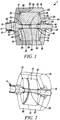
- Two embodiments of HME devices according to the present invention will now be described, by way of example, with reference to the accompanying drawings, in which:
- Figure 1
- is a cross-sectional side elevation view of the first embodiment HME device;
- Figure 2
- is a perspective, cut-away, cross-sectional view of HME of
Figure 1 ; - Figure 3
- is a cross-sectional side elevation view of the second embodiment HME; and
- Figure 4
- is a perspective, cut-away, cross-sectional view of the HME of
Figure 3 . - With reference first to
Figure 1 and 2 there is shown anHME device 1 having anouter housing 10 of circular section with a patient end coupling orinlet 11 having a luer taperedinner surface 11' adapted to fit onto a mating male connector at the end of a breathing device (not shown) such as an endotracheal or tracheostomy tube. At the opposite end of the device 1 a machine end coupling oroutlet 12 is axially aligned with thepatient end coupling 11. Between thepatient end coupling 11 and themachine end coupling 12 thehousing 10 has a transversely or radially enlargedcentral region 13. Thecentral region 13 of thehousing 10 contains anHME element 14 in the form of a strip of corrugated paper treated with a hygroscopic salt to promote the absorption of moisture, the strip being wound into a circular coil. The corrugations of the paper strip are aligned parallel with the axis of the device so that air can flow along them. Thepatient face 15 andmachine face 16 of theelement 14 are spaced slightly from thehousing 10 in thecentral region 13 so that air can flow through the element across the entire surface of both faces. TheHME element 14 is supported on opposite sides in thehousing 10 by twoannular rings - The
central region 13 of thehousing 10 is formed separately of thepatient end coupling 11 and themachine end coupling 12. The major part of the length of thecentral region 13 is provided by acylindrical portion 23 of circular section and constant diameter along its length. At opposite ends, thecentral region 13 hasrespective end walls central region 13 is moulded in twoparts HME element 14. The twoparts mating end surfaces parts parts - The
patient end coupling 11 is a one-piece integral moulding of a rigid (non-foamed) plastics material, such as nylon, of generally cylindrical shape and circular section. Thepatient end 31 of thecoupling 11 is formed with an in-turnedsleeve 32 theinner surface 11' of which is tapered and is adapted provide a female coupling for fitting on the outside of a conventional 15mm male coupling (not shown) attached to a breathing tube or the like. About half way along the coupling 11 ashallow flange 34 projects radially outwardly and abuts the outer surface of thepatient end wall 24 of thecentral section 13. The part of thecoupling 11 on the machine side of theflange 34 is divided into a slightly enlargedcylindrical section 35 and atapered nose section 36. Thecylindrical section 35 is a close fit in acentral opening 37 in thepatient end wall 24 where it is bonded in position such as with an adhesive or solvent. Thenose section 36 tapers internally and externally to a reduced diameter at its machine end. - The
machine end coupling 12 is also a one-piece moulding shaped to provide a male tapered connection and, in this respect includes acylindrical spigot 42 of circular section having a constant internal diameter and an external diameter tapering along its length, reducing in diameter towards the free, machine end 43 of the coupling. Thespigot 42 is supported at its opposite, patient end where it joins with a tapering nose portion 44 projecting inwardly of thehousing 10. Themachine end coupling 12 is completed by an integral cylindricalouter sleeve 45 projecting axially outwardly from the nose portion 44 around thespigot 42 along about one half its length. Theouter sleeve 45 is terminated by a narrow, outwardly-projectingflange 46 and is a close fit within acentral opening 47 in themachine end wall 25 into which it is bonded, with the flange abutting the outside surface of the wall around the opening. The inner surface of theouter sleeve 45 and the outer surface of thespigot 42 extending with the sleeve are spaced from one another to form anannular recess 48 into which the forward end of a mating female coupling (not shown) can be received. - The
HME element 14 is a coil of treated corrugated paper wound into an annular form about a hollowtubular sleeve 50 extending axially through the element between its opposite ends. Thesleeve 50 is flared outwardly at opposite ends 51 and 52 to form enlarged, tapering openings into the sleeve. Thesleeve 50 is blocked midway along by avalve 53, such as a duckbill valve, that can be opened by extending a suction catheter along the sleeve. - The
nose 36 of thepatient end coupling 11 and the nose 44 of themachine end coupling 12 project a short distance into the respective flared ends 51 and 52 of thesleeve 50 but leave a space between the outside of each nose and the inside of the respective flared end to provide respective annulargas flow passages passages annular cavities noses 36 and 44 of thecouplings respective end face HME element 14 and the inside surface of asloping end walls central section 13. - In use, the
patient end coupling 11 is fitted on to a coupling at the machine end of a breathing device, such as a tracheal tube or face mask. When the patient exhales, warm, moist air flows forwardly through thecoupling 11 and out of the end of thenose portion 36 into the patient end of thesleeve 50. Further flow forwardly is prevented by thevalve 53 so the air instead flows rearwardly through theannular passage 54 into thecavity 56 where the air is dispersed evenly over the rear-facingface 15 of theHME element 14. The even distribution is aided by the width of thecavity 56 and the slope on theend wall 24. The air then flows through theHME element 14 along the spaces around the corrugations and between adjacent turns of the coil. As it does this the air gives up a large part of its heat and moisture to theHME element 14. The air then emerges from the forward-facingface 16 of theelement 14 into themachine end cavity 57 from where it changes direction and flows rearwardly through theannular passage 55 into the machine end of thesleeve 50. Further flow in the same direction is blocked by thevalve 53 so the air reverses direction to flow forwardly out along the bore of themachine end coupling 12. - When the patient inhales, or when air is supplied by a ventilator or the like in the opposite direction, the air follows the same path through the
device 1 but in the opposite direction. The inhaled air is cooler and drier than the exhaled air so, as this passes through theHME element 14, it takes up the major part of the warmth and moisture absorbed in the element during the previous exhalation phase thereby warming and moistening the air that flows to the patient. - The thickness and the thermally-insulative nature of the foamed material from which the wall of the
central region 13 of thehousing 10 is made help maintain the interior of theHME 1 at a stable temperature closer to body temperature than conventional HMEs during both exhalation and inhalation. This has been found to increase the efficiency of the HME compared with conventional HMEs. This increase in efficiency brings the performance of the HME closer to that of active humidifiers and thereby makes the HME a more viable alternative where a high level of warming and humidification is required. The lower cost, ease of use, the absence of any requirement for power or water supply are considerable advantages. The HME device can be disposed of after a single use, thereby avoiding the infection risk and cleaning requirements of active humidifiers. - Various modifications within the scope of the present invention are possible to the HME described with reference to
Figures 1 and 2 . Although theHME element 14 is described as having flat end surfaces 15 and 16 it would be possible for the element to have alternative configurations as, for example shown inFigures 3 and 4 . TheHME 101 shown inFigures 3 and 4 is similar to that shown inFigures 1 and 2 with anidentical housing 110 but where theHME element 114 differs by having opposite end surfaces 115 and 116 of a shallow, concave, conical shape forming an included angle of about 160°. The simple annular rings used to support the HME element in the housing in the embodiment ofFigures 1 and 2 are replaced in the second embodiment with wheel-like supports supports outer rim 120 located between the outer edge of therespective end face 115 and 116 and theadjacent end wall support central hub 121 extending around the outside of the nose portion of the respective coupling and attached with the respective rim by eight radially extendingvanes 122. Thevanes 122 are spaced evenly around eachsupport wheel hub 121 where they are relatively high to theouter rim 120 where they are relatively small. The shape of thevanes 122 is such as to conform to the shape of thecavity HME element 114 and the facingsloping end walls housing 110. The edges of thevanes 122 contact theend face 115 and 116 of theHME element 114 and the inside of the facingend wall cavity vanes 122, may lead to a more even distribution of gas over theend face 115 and 116 of theHME element 114, which in turn, helps maintain the efficiency of the HME for a longer period. - The HME element need not be made of a coil of corrugated, treated paper but could be of other materials used in conventional HME elements, such as foam or hollow fibres. It is not essential that the HME device and HME element be circular in section since they could be of other shapes such as oval or rectangular, although the circular shape has been found to give the highest efficiency. Although the HMEs described above have folded air flow paths at both ends, it would be possible instead for an HME element to extend across the entire width of the housing and for the inlet and outlet to open onto the centre of the end faces of the element. Although the HMEs described above have an axial form where the inlet and outlet are axially aligned, the thermally-insulating housing of the present invention may also benefit HMEs having other conventional alternative configurations such as a T-shape configuration with two HME elements mounted at opposite ends of a straight tubular housing extending transversely of the connection port by which the device is fitted onto a tracheostomy tube or the like.
Claims (13)
- An HME device (1, 101) having a housing (10, 110) providing an inlet coupling (11), an outlet coupling (12) and a transversely enlarged region (13) between the inlet and outlet couplings, the device including an HME element (14, 114) having an outer surface retained in the enlarged region and opposite end faces (15, 16, 115, 116) spaced slightly from the housing (10,110) in the enlarged region (13) so that air can flow through the element across the entire surface of both faces (15,15,115,116), characterised in that the wall of the housing at least in the enlarged region includes a major part of its thickness of a foamed plastics material such as to provide thermal insulation of the housing (10, 110) around the HME element (14, 114).
- An HME device according to Claim 1, characterised in that the foamed plastics material has a thermal conductivity of substantially 0.03 W/(m.K) or less.
- An HME device according to Claim 1 or 2, characterised in that the ratio of the wall thickness of the enlarged region (13) to its external diameter is substantially 1:8.
- An HME device according to any one of the preceding claims, characterised in that the inlet (11) and outlet (12) are axially aligned with one another.
- An HME device according to any one of the preceding claims, characterised in that the enlarged region (13) includes a cylindrical portion (23) of circular section and two opposite end wall portions (24 and 25, 124 and 125) extending laterally to the inlet (11) and outlet (12) respectively.
- An HME device according to Claim 5, characterised in that both the cylindrical portion (23) and the wall portions (24 and 25, 124 and 125) are of a foamed plastics material through a major part of their thickness.
- An HME device according to Claim 5 or 6, characterised in that at least the inner surface of the opposite end wall portions (24 and 25, 124 and 125) extend at an angle to the normal to the axis of HME device.
- An HME device according to any one of the preceding claims, characterised in that the inlet and outlet (11 and 12) are components formed separate from the enlarged region (13) and attached with the enlarged region.
- An HME device according to any one of the preceding claims, characterised in that the HME element is a coil of corrugated paper (14, 114).
- An HME device according to Claim 9, characterised in that the coil of corrugated paper (14, 114) is wound about a hollow tubular sleeve (50).
- An HME device according to any one of the preceding claims, characterised in that the housing (10, 110) is formed in two parts (26 and 27) joined together at mating end surfaces (28 and 29) in the enlarged region (13).
- An HME device according to Claim 11, characterised in that the mating end surfaces (28 and 29) are inclined in opposite senses at an angle to the normal to the axis of the device.
- An HME device according to any one of the preceding claims, characterised in that opposite end surfaces (115 and 116) of the HME element (114) each form a shallow, concave, conical shape.
Applications Claiming Priority (2)
| Application Number | Priority Date | Filing Date | Title |
|---|---|---|---|
| GBGB1610715.3A GB201610715D0 (en) | 2016-06-18 | 2016-06-18 | Heat and moisture exchange devices |
| PCT/GB2017/000073 WO2017216508A1 (en) | 2016-06-18 | 2017-05-15 | Heat and moisture exchange devices |
Publications (2)
| Publication Number | Publication Date |
|---|---|
| EP3471812A1 EP3471812A1 (en) | 2019-04-24 |
| EP3471812B1 true EP3471812B1 (en) | 2020-12-09 |
Family
ID=56895265
Family Applications (1)
| Application Number | Title | Priority Date | Filing Date |
|---|---|---|---|
| EP17724396.1A Active EP3471812B1 (en) | 2016-06-18 | 2017-05-15 | Heat and moisture exchange devices |
Country Status (5)
| Country | Link |
|---|---|
| US (1) | US12161811B2 (en) |
| EP (1) | EP3471812B1 (en) |
| JP (2) | JP2019517894A (en) |
| GB (1) | GB201610715D0 (en) |
| WO (1) | WO2017216508A1 (en) |
Families Citing this family (3)
| Publication number | Priority date | Publication date | Assignee | Title |
|---|---|---|---|---|
| GB202103529D0 (en) | 2021-03-15 | 2021-04-28 | Smiths Medical International Ltd | Gas-treatment devices |
| GB202105159D0 (en) | 2021-04-12 | 2021-05-26 | Smiths Medical International Ltd | HME devices |
| GB202107383D0 (en) * | 2021-05-24 | 2021-07-07 | Smiths Medical International Ltd | Heat and moisture exchange devices, elements and assemblies |
Family Cites Families (31)
| Publication number | Priority date | Publication date | Assignee | Title |
|---|---|---|---|---|
| SE414708B (en) * | 1972-11-06 | 1980-08-18 | Norabel Ab | DEVICE FOR HEATING AND HEATING THE INHALED AIR AT TRAKEOTOMIOCH ENDOTRAKEAL INTUBATION |
| SE462367B (en) | 1988-01-22 | 1990-06-18 | Respaid Ab | RESPIRATORY VALVE INTENDED TO BE USED AS A VALVE VALVE |
| DD278501A1 (en) | 1988-12-27 | 1990-05-09 | Medizin Labortechnik Veb K | DEVICE FOR ATTACHING AND HUMIDIFYING VENTILATION GASES |
| GB8916361D0 (en) | 1989-07-18 | 1989-09-06 | Smiths Industries Plc | Filters |
| GB8923785D0 (en) * | 1989-10-23 | 1989-12-13 | Edmunds David M | Device |
| NZ238544A (en) | 1990-06-18 | 1994-10-26 | Ponnet Gilman En Anthony | Respirator with hygroscopic material adjacent outlet to patient |
| SE469925B (en) * | 1992-02-21 | 1993-10-11 | Gibeck Respiration Ab | A filter device for connection to a person's respiratory system comprising a housing containing a moisture-heat-exchanging material and a bacteria-absorbing filter consisting of a pleated, air-permeable material |
| GB2267840B (en) | 1992-06-19 | 1995-09-20 | Intersurgical Ltd | Improvements in heat and moisture exchangers |
| GB9215154D0 (en) * | 1992-07-16 | 1992-08-26 | Smiths Industries Plc | Tubing and humidification systems |
| US5505768A (en) | 1994-10-11 | 1996-04-09 | Altadonna; Anthony J. | Humidity moisture exchanger |
| SE9502354L (en) | 1995-06-28 | 1996-12-29 | Respaid Ab | Respiratory Aids |
| US5595173A (en) * | 1995-06-29 | 1997-01-21 | Dodd, Jr.; Nevin W. | Rehumidification filter for ventilation mask |
| GB9514527D0 (en) | 1995-07-15 | 1995-09-13 | Smiths Industries Plc | Heat and moisture exchangers |
| AU7472296A (en) | 1995-10-27 | 1997-05-15 | Nellcor Puritan Bennett Incorporated | Heat exchanger strip |
| GB9701995D0 (en) | 1997-01-31 | 1997-03-19 | Smiths Industries Plc | Heat and moisture exchangers and systems |
| SE512029C2 (en) | 1998-05-14 | 2000-01-17 | Atos Medical Ab | Speech valve with filter |
| IT1318430B1 (en) | 2000-03-29 | 2003-08-25 | Mallinckrodt Holdings B V | DEVICE FOR PASSIVE HUMIDIFICATION OF TRACHEOSTOMIZED OR INTUBATED PATIENTS. |
| SE516666C2 (en) | 2000-06-08 | 2002-02-12 | Hudson Rci Ab | Moisture heat exchanger for connecting to tracheal channel, contains bodies for distribuing oxygen over air inlet surfaces of moisture heat exchange bodies |
| IT1316950B1 (en) | 2000-11-23 | 2003-05-13 | Bellmafiok S R L | SELF-HUMIDIFYING DEVICE FOR TRACHEOSTOMY. |
| DE20114355U1 (en) | 2001-08-30 | 2001-11-15 | Schmid, Herbert, 57612 Obererbach | Artificial nose for patients with spontaneous breathing via tracheostomy or endotrachial tube |
| GB0218954D0 (en) | 2002-08-15 | 2002-09-25 | Intersurgical Ltd | Improvements relating to tracheostomy devices |
| US7347203B2 (en) * | 2002-09-16 | 2008-03-25 | Thayer Medical Corporation | Heat and moisture filter exchanger and method |
| DE20302580U1 (en) | 2003-02-18 | 2003-04-24 | Neubauer, Norbert, 38820 Halberstadt | Device for exchanging moisture and heat in breathing air for patients lacking a natural nose function, comprises a housing holding elastic elements impregnated with active substances, and elastic filter elements |
| GB0329054D0 (en) | 2003-12-16 | 2004-01-14 | Smiths Group Plc | Gas-treatment devices |
| GB0329297D0 (en) | 2003-12-18 | 2004-01-21 | Smiths Group Plc | Gas-treatment devices |
| WO2006072768A1 (en) | 2005-01-06 | 2006-07-13 | Smiths Group Plc | Gas-treatment devices |
| US7624731B2 (en) | 2005-03-16 | 2009-12-01 | Dennis R Walstrom | HME/MDI apparatus having MDI in parallel to HME |
| GB0511517D0 (en) | 2005-06-07 | 2005-07-13 | Smiths Group Plc | Medico-surgical apparatus |
| CN103180004B (en) * | 2010-09-10 | 2017-04-26 | 费雪派克医疗保健有限公司 | Components for conveying gases |
| WO2015052681A1 (en) * | 2013-10-11 | 2015-04-16 | Fisher & Paykel Healthcare Limited | Hme and compact breathing apparatus |
| GB201400779D0 (en) | 2014-01-17 | 2014-03-05 | Smiths Medical Int Ltd | Gas-treatment devices and apparatus |
-
2016
- 2016-06-18 GB GBGB1610715.3A patent/GB201610715D0/en not_active Ceased
-
2017
- 2017-05-15 US US16/302,254 patent/US12161811B2/en active Active
- 2017-05-15 WO PCT/GB2017/000073 patent/WO2017216508A1/en not_active Ceased
- 2017-05-15 EP EP17724396.1A patent/EP3471812B1/en active Active
- 2017-05-15 JP JP2018566223A patent/JP2019517894A/en active Pending
-
2021
- 2021-11-08 JP JP2021182161A patent/JP7102650B2/en active Active
Non-Patent Citations (1)
| Title |
|---|
| None * |
Also Published As
| Publication number | Publication date |
|---|---|
| JP2022010163A (en) | 2022-01-14 |
| US20190275282A1 (en) | 2019-09-12 |
| GB201610715D0 (en) | 2016-08-03 |
| JP2019517894A (en) | 2019-06-27 |
| JP7102650B2 (en) | 2022-07-20 |
| US12161811B2 (en) | 2024-12-10 |
| EP3471812A1 (en) | 2019-04-24 |
| WO2017216508A1 (en) | 2017-12-21 |
Similar Documents
| Publication | Publication Date | Title |
|---|---|---|
| US11471635B2 (en) | Breathing assistance apparatus | |
| US9878121B2 (en) | Ventilation mask with heat and moisture exchange device | |
| US9919124B2 (en) | Delivery adaptor for ventilation system | |
| EP4049701B1 (en) | Patient interface device and ventilation treatment apparatus | |
| US20080185007A1 (en) | Sealing nasal cannula | |
| US20120097156A1 (en) | Positive airway pressure therapy mask humidification systems and methods | |
| JP7102650B2 (en) | Heat and humidity exchange device | |
| CN104470572B (en) | pediatric full face mask | |
| CA2609187A1 (en) | Patient interface assemblies for use in ventilator systems to deliver medication to a patient | |
| CN105169541A (en) | Ventilation control device and breathing mask equipment with same | |
| JP2020512134A (en) | Moisture escape conduits and systems | |
| GB2540456A (en) | Heat and moisture exchange devices | |
| JP4881377B2 (en) | Medical surgical instruments | |
| US20260115403A1 (en) | Heat and moisture exchange devices | |
| US20260115404A1 (en) | Heat and moisture exchange devices | |
| US20240216637A1 (en) | Heat and moisture exchange devices, elements and assemblies | |
| CN215938641U (en) | Heating and humidifying oral oxygen inhalation tube | |
| JPS6152708B2 (en) |
Legal Events
| Date | Code | Title | Description |
|---|---|---|---|
| STAA | Information on the status of an ep patent application or granted ep patent |
Free format text: STATUS: UNKNOWN |
|
| STAA | Information on the status of an ep patent application or granted ep patent |
Free format text: STATUS: THE INTERNATIONAL PUBLICATION HAS BEEN MADE |
|
| PUAI | Public reference made under article 153(3) epc to a published international application that has entered the european phase |
Free format text: ORIGINAL CODE: 0009012 |
|
| STAA | Information on the status of an ep patent application or granted ep patent |
Free format text: STATUS: REQUEST FOR EXAMINATION WAS MADE |
|
| 17P | Request for examination filed |
Effective date: 20181109 |
|
| AK | Designated contracting states |
Kind code of ref document: A1 Designated state(s): AL AT BE BG CH CY CZ DE DK EE ES FI FR GB GR HR HU IE IS IT LI LT LU LV MC MK MT NL NO PL PT RO RS SE SI SK SM TR |
|
| AX | Request for extension of the european patent |
Extension state: BA ME |
|
| DAV | Request for validation of the european patent (deleted) | ||
| DAX | Request for extension of the european patent (deleted) | ||
| GRAP | Despatch of communication of intention to grant a patent |
Free format text: ORIGINAL CODE: EPIDOSNIGR1 |
|
| STAA | Information on the status of an ep patent application or granted ep patent |
Free format text: STATUS: GRANT OF PATENT IS INTENDED |
|
| INTG | Intention to grant announced |
Effective date: 20200814 |
|
| GRAS | Grant fee paid |
Free format text: ORIGINAL CODE: EPIDOSNIGR3 |
|
| GRAA | (expected) grant |
Free format text: ORIGINAL CODE: 0009210 |
|
| STAA | Information on the status of an ep patent application or granted ep patent |
Free format text: STATUS: THE PATENT HAS BEEN GRANTED |
|
| AK | Designated contracting states |
Kind code of ref document: B1 Designated state(s): AL AT BE BG CH CY CZ DE DK EE ES FI FR GB GR HR HU IE IS IT LI LT LU LV MC MK MT NL NO PL PT RO RS SE SI SK SM TR |
|
| REG | Reference to a national code |
Ref country code: GB Ref legal event code: FG4D |
|
| REG | Reference to a national code |
Ref country code: AT Ref legal event code: REF Ref document number: 1342757 Country of ref document: AT Kind code of ref document: T Effective date: 20201215 Ref country code: CH Ref legal event code: EP |
|
| REG | Reference to a national code |
Ref country code: DE Ref legal event code: R096 Ref document number: 602017029237 Country of ref document: DE |
|
| REG | Reference to a national code |
Ref country code: IE Ref legal event code: FG4D |
|
| PG25 | Lapsed in a contracting state [announced via postgrant information from national office to epo] |
Ref country code: GR Free format text: LAPSE BECAUSE OF FAILURE TO SUBMIT A TRANSLATION OF THE DESCRIPTION OR TO PAY THE FEE WITHIN THE PRESCRIBED TIME-LIMIT Effective date: 20210310 Ref country code: FI Free format text: LAPSE BECAUSE OF FAILURE TO SUBMIT A TRANSLATION OF THE DESCRIPTION OR TO PAY THE FEE WITHIN THE PRESCRIBED TIME-LIMIT Effective date: 20201209 Ref country code: RS Free format text: LAPSE BECAUSE OF FAILURE TO SUBMIT A TRANSLATION OF THE DESCRIPTION OR TO PAY THE FEE WITHIN THE PRESCRIBED TIME-LIMIT Effective date: 20201209 Ref country code: NO Free format text: LAPSE BECAUSE OF FAILURE TO SUBMIT A TRANSLATION OF THE DESCRIPTION OR TO PAY THE FEE WITHIN THE PRESCRIBED TIME-LIMIT Effective date: 20210309 |
|
| REG | Reference to a national code |
Ref country code: AT Ref legal event code: MK05 Ref document number: 1342757 Country of ref document: AT Kind code of ref document: T Effective date: 20201209 |
|
| PG25 | Lapsed in a contracting state [announced via postgrant information from national office to epo] |
Ref country code: SE Free format text: LAPSE BECAUSE OF FAILURE TO SUBMIT A TRANSLATION OF THE DESCRIPTION OR TO PAY THE FEE WITHIN THE PRESCRIBED TIME-LIMIT Effective date: 20201209 Ref country code: BG Free format text: LAPSE BECAUSE OF FAILURE TO SUBMIT A TRANSLATION OF THE DESCRIPTION OR TO PAY THE FEE WITHIN THE PRESCRIBED TIME-LIMIT Effective date: 20210309 Ref country code: LV Free format text: LAPSE BECAUSE OF FAILURE TO SUBMIT A TRANSLATION OF THE DESCRIPTION OR TO PAY THE FEE WITHIN THE PRESCRIBED TIME-LIMIT Effective date: 20201209 |
|
| REG | Reference to a national code |
Ref country code: NL Ref legal event code: MP Effective date: 20201209 |
|
| PG25 | Lapsed in a contracting state [announced via postgrant information from national office to epo] |
Ref country code: HR Free format text: LAPSE BECAUSE OF FAILURE TO SUBMIT A TRANSLATION OF THE DESCRIPTION OR TO PAY THE FEE WITHIN THE PRESCRIBED TIME-LIMIT Effective date: 20201209 Ref country code: NL Free format text: LAPSE BECAUSE OF FAILURE TO SUBMIT A TRANSLATION OF THE DESCRIPTION OR TO PAY THE FEE WITHIN THE PRESCRIBED TIME-LIMIT Effective date: 20201209 |
|
| REG | Reference to a national code |
Ref country code: LT Ref legal event code: MG9D |
|
| PG25 | Lapsed in a contracting state [announced via postgrant information from national office to epo] |
Ref country code: SK Free format text: LAPSE BECAUSE OF FAILURE TO SUBMIT A TRANSLATION OF THE DESCRIPTION OR TO PAY THE FEE WITHIN THE PRESCRIBED TIME-LIMIT Effective date: 20201209 Ref country code: PT Free format text: LAPSE BECAUSE OF FAILURE TO SUBMIT A TRANSLATION OF THE DESCRIPTION OR TO PAY THE FEE WITHIN THE PRESCRIBED TIME-LIMIT Effective date: 20210409 Ref country code: RO Free format text: LAPSE BECAUSE OF FAILURE TO SUBMIT A TRANSLATION OF THE DESCRIPTION OR TO PAY THE FEE WITHIN THE PRESCRIBED TIME-LIMIT Effective date: 20201209 Ref country code: SM Free format text: LAPSE BECAUSE OF FAILURE TO SUBMIT A TRANSLATION OF THE DESCRIPTION OR TO PAY THE FEE WITHIN THE PRESCRIBED TIME-LIMIT Effective date: 20201209 Ref country code: LT Free format text: LAPSE BECAUSE OF FAILURE TO SUBMIT A TRANSLATION OF THE DESCRIPTION OR TO PAY THE FEE WITHIN THE PRESCRIBED TIME-LIMIT Effective date: 20201209 Ref country code: EE Free format text: LAPSE BECAUSE OF FAILURE TO SUBMIT A TRANSLATION OF THE DESCRIPTION OR TO PAY THE FEE WITHIN THE PRESCRIBED TIME-LIMIT Effective date: 20201209 Ref country code: CZ Free format text: LAPSE BECAUSE OF FAILURE TO SUBMIT A TRANSLATION OF THE DESCRIPTION OR TO PAY THE FEE WITHIN THE PRESCRIBED TIME-LIMIT Effective date: 20201209 |
|
| PG25 | Lapsed in a contracting state [announced via postgrant information from national office to epo] |
Ref country code: AT Free format text: LAPSE BECAUSE OF FAILURE TO SUBMIT A TRANSLATION OF THE DESCRIPTION OR TO PAY THE FEE WITHIN THE PRESCRIBED TIME-LIMIT Effective date: 20201209 Ref country code: PL Free format text: LAPSE BECAUSE OF FAILURE TO SUBMIT A TRANSLATION OF THE DESCRIPTION OR TO PAY THE FEE WITHIN THE PRESCRIBED TIME-LIMIT Effective date: 20201209 |
|
| REG | Reference to a national code |
Ref country code: DE Ref legal event code: R097 Ref document number: 602017029237 Country of ref document: DE |
|
| PG25 | Lapsed in a contracting state [announced via postgrant information from national office to epo] |
Ref country code: IS Free format text: LAPSE BECAUSE OF FAILURE TO SUBMIT A TRANSLATION OF THE DESCRIPTION OR TO PAY THE FEE WITHIN THE PRESCRIBED TIME-LIMIT Effective date: 20210409 |
|
| PLBE | No opposition filed within time limit |
Free format text: ORIGINAL CODE: 0009261 |
|
| STAA | Information on the status of an ep patent application or granted ep patent |
Free format text: STATUS: NO OPPOSITION FILED WITHIN TIME LIMIT |
|
| PG25 | Lapsed in a contracting state [announced via postgrant information from national office to epo] |
Ref country code: AL Free format text: LAPSE BECAUSE OF FAILURE TO SUBMIT A TRANSLATION OF THE DESCRIPTION OR TO PAY THE FEE WITHIN THE PRESCRIBED TIME-LIMIT Effective date: 20201209 Ref country code: IT Free format text: LAPSE BECAUSE OF FAILURE TO SUBMIT A TRANSLATION OF THE DESCRIPTION OR TO PAY THE FEE WITHIN THE PRESCRIBED TIME-LIMIT Effective date: 20201209 |
|
| 26N | No opposition filed |
Effective date: 20210910 |
|
| PG25 | Lapsed in a contracting state [announced via postgrant information from national office to epo] |
Ref country code: DK Free format text: LAPSE BECAUSE OF FAILURE TO SUBMIT A TRANSLATION OF THE DESCRIPTION OR TO PAY THE FEE WITHIN THE PRESCRIBED TIME-LIMIT Effective date: 20201209 Ref country code: SI Free format text: LAPSE BECAUSE OF FAILURE TO SUBMIT A TRANSLATION OF THE DESCRIPTION OR TO PAY THE FEE WITHIN THE PRESCRIBED TIME-LIMIT Effective date: 20201209 |
|
| REG | Reference to a national code |
Ref country code: CH Ref legal event code: PL |
|
| PG25 | Lapsed in a contracting state [announced via postgrant information from national office to epo] |
Ref country code: ES Free format text: LAPSE BECAUSE OF FAILURE TO SUBMIT A TRANSLATION OF THE DESCRIPTION OR TO PAY THE FEE WITHIN THE PRESCRIBED TIME-LIMIT Effective date: 20201209 Ref country code: MC Free format text: LAPSE BECAUSE OF FAILURE TO SUBMIT A TRANSLATION OF THE DESCRIPTION OR TO PAY THE FEE WITHIN THE PRESCRIBED TIME-LIMIT Effective date: 20201209 Ref country code: LU Free format text: LAPSE BECAUSE OF NON-PAYMENT OF DUE FEES Effective date: 20210515 Ref country code: LI Free format text: LAPSE BECAUSE OF NON-PAYMENT OF DUE FEES Effective date: 20210531 Ref country code: CH Free format text: LAPSE BECAUSE OF NON-PAYMENT OF DUE FEES Effective date: 20210531 |
|
| REG | Reference to a national code |
Ref country code: BE Ref legal event code: MM Effective date: 20210531 |
|
| PG25 | Lapsed in a contracting state [announced via postgrant information from national office to epo] |
Ref country code: IE Free format text: LAPSE BECAUSE OF NON-PAYMENT OF DUE FEES Effective date: 20210515 |
|
| PG25 | Lapsed in a contracting state [announced via postgrant information from national office to epo] |
Ref country code: IS Free format text: LAPSE BECAUSE OF FAILURE TO SUBMIT A TRANSLATION OF THE DESCRIPTION OR TO PAY THE FEE WITHIN THE PRESCRIBED TIME-LIMIT Effective date: 20210409 Ref country code: FR Free format text: LAPSE BECAUSE OF NON-PAYMENT OF DUE FEES Effective date: 20210531 |
|
| PG25 | Lapsed in a contracting state [announced via postgrant information from national office to epo] |
Ref country code: BE Free format text: LAPSE BECAUSE OF NON-PAYMENT OF DUE FEES Effective date: 20210531 |
|
| P01 | Opt-out of the competence of the unified patent court (upc) registered |
Effective date: 20230419 |
|
| PG25 | Lapsed in a contracting state [announced via postgrant information from national office to epo] |
Ref country code: CY Free format text: LAPSE BECAUSE OF FAILURE TO SUBMIT A TRANSLATION OF THE DESCRIPTION OR TO PAY THE FEE WITHIN THE PRESCRIBED TIME-LIMIT Effective date: 20201209 |
|
| PG25 | Lapsed in a contracting state [announced via postgrant information from national office to epo] |
Ref country code: HU Free format text: LAPSE BECAUSE OF FAILURE TO SUBMIT A TRANSLATION OF THE DESCRIPTION OR TO PAY THE FEE WITHIN THE PRESCRIBED TIME-LIMIT; INVALID AB INITIO Effective date: 20170515 |
|
| PG25 | Lapsed in a contracting state [announced via postgrant information from national office to epo] |
Ref country code: MK Free format text: LAPSE BECAUSE OF FAILURE TO SUBMIT A TRANSLATION OF THE DESCRIPTION OR TO PAY THE FEE WITHIN THE PRESCRIBED TIME-LIMIT Effective date: 20201209 |
|
| PG25 | Lapsed in a contracting state [announced via postgrant information from national office to epo] |
Ref country code: MT Free format text: LAPSE BECAUSE OF FAILURE TO SUBMIT A TRANSLATION OF THE DESCRIPTION OR TO PAY THE FEE WITHIN THE PRESCRIBED TIME-LIMIT Effective date: 20201209 |
|
| REG | Reference to a national code |
Ref country code: DE Ref legal event code: R081 Ref document number: 602017029237 Country of ref document: DE Owner name: ICU MEDICAL INTERNATIONAL LTD., ASHFORD, GB Free format text: FORMER OWNER: SMITHS MEDICAL INTERNATIONAL LTD., ASHFORD, KENT, GB |
|
| PG25 | Lapsed in a contracting state [announced via postgrant information from national office to epo] |
Ref country code: TR Free format text: LAPSE BECAUSE OF FAILURE TO SUBMIT A TRANSLATION OF THE DESCRIPTION OR TO PAY THE FEE WITHIN THE PRESCRIBED TIME-LIMIT Effective date: 20201209 |
|
| PGFP | Annual fee paid to national office [announced via postgrant information from national office to epo] |
Ref country code: GB Payment date: 20260312 Year of fee payment: 10 |
|
| PGFP | Annual fee paid to national office [announced via postgrant information from national office to epo] |
Ref country code: DE Payment date: 20260317 Year of fee payment: 10 |