EP3471522A2 - Flexible and configurable rack power distribution unit - Google Patents
Flexible and configurable rack power distribution unit Download PDFInfo
- Publication number
- EP3471522A2 EP3471522A2 EP18198327.1A EP18198327A EP3471522A2 EP 3471522 A2 EP3471522 A2 EP 3471522A2 EP 18198327 A EP18198327 A EP 18198327A EP 3471522 A2 EP3471522 A2 EP 3471522A2
- Authority
- EP
- European Patent Office
- Prior art keywords
- outlet
- type
- outlets
- board
- retaining
- Prior art date
- Legal status (The legal status is an assumption and is not a legal conclusion. Google has not performed a legal analysis and makes no representation as to the accuracy of the status listed.)
- Granted
Links
Images










Classifications
-
- H—ELECTRICITY
- H01—ELECTRIC ELEMENTS
- H01R—ELECTRICALLY-CONDUCTIVE CONNECTIONS; STRUCTURAL ASSOCIATIONS OF A PLURALITY OF MUTUALLY-INSULATED ELECTRICAL CONNECTING ELEMENTS; COUPLING DEVICES; CURRENT COLLECTORS
- H01R13/00—Details of coupling devices of the kinds covered by groups H01R12/70 or H01R24/00 - H01R33/00
- H01R13/46—Bases; Cases
- H01R13/502—Bases; Cases composed of different pieces
-
- H—ELECTRICITY
- H01—ELECTRIC ELEMENTS
- H01R—ELECTRICALLY-CONDUCTIVE CONNECTIONS; STRUCTURAL ASSOCIATIONS OF A PLURALITY OF MUTUALLY-INSULATED ELECTRICAL CONNECTING ELEMENTS; COUPLING DEVICES; CURRENT COLLECTORS
- H01R25/00—Coupling parts adapted for simultaneous co-operation with two or more identical counterparts, e.g. for distributing energy to two or more circuits
- H01R25/16—Rails or bus-bars provided with a plurality of discrete connecting locations for counterparts
- H01R25/165—Connecting locations formed by surface mounted apparatus
-
- H—ELECTRICITY
- H01—ELECTRIC ELEMENTS
- H01R—ELECTRICALLY-CONDUCTIVE CONNECTIONS; STRUCTURAL ASSOCIATIONS OF A PLURALITY OF MUTUALLY-INSULATED ELECTRICAL CONNECTING ELEMENTS; COUPLING DEVICES; CURRENT COLLECTORS
- H01R13/00—Details of coupling devices of the kinds covered by groups H01R12/70 or H01R24/00 - H01R33/00
- H01R13/46—Bases; Cases
- H01R13/516—Means for holding or embracing insulating body, e.g. casing, hoods
- H01R13/518—Means for holding or embracing insulating body, e.g. casing, hoods for holding or embracing several coupling parts, e.g. frames
-
- H—ELECTRICITY
- H01—ELECTRIC ELEMENTS
- H01R—ELECTRICALLY-CONDUCTIVE CONNECTIONS; STRUCTURAL ASSOCIATIONS OF A PLURALITY OF MUTUALLY-INSULATED ELECTRICAL CONNECTING ELEMENTS; COUPLING DEVICES; CURRENT COLLECTORS
- H01R25/00—Coupling parts adapted for simultaneous co-operation with two or more identical counterparts, e.g. for distributing energy to two or more circuits
- H01R25/006—Coupling parts adapted for simultaneous co-operation with two or more identical counterparts, e.g. for distributing energy to two or more circuits the coupling part being secured to apparatus or structure, e.g. duplex wall receptacle
-
- H—ELECTRICITY
- H01—ELECTRIC ELEMENTS
- H01R—ELECTRICALLY-CONDUCTIVE CONNECTIONS; STRUCTURAL ASSOCIATIONS OF A PLURALITY OF MUTUALLY-INSULATED ELECTRICAL CONNECTING ELEMENTS; COUPLING DEVICES; CURRENT COLLECTORS
- H01R27/00—Coupling parts adapted for co-operation with two or more dissimilar counterparts
-
- H—ELECTRICITY
- H01—ELECTRIC ELEMENTS
- H01R—ELECTRICALLY-CONDUCTIVE CONNECTIONS; STRUCTURAL ASSOCIATIONS OF A PLURALITY OF MUTUALLY-INSULATED ELECTRICAL CONNECTING ELEMENTS; COUPLING DEVICES; CURRENT COLLECTORS
- H01R27/00—Coupling parts adapted for co-operation with two or more dissimilar counterparts
- H01R27/02—Coupling parts adapted for co-operation with two or more dissimilar counterparts for simultaneous co-operation with two or more dissimilar counterparts
-
- H—ELECTRICITY
- H05—ELECTRIC TECHNIQUES NOT OTHERWISE PROVIDED FOR
- H05K—PRINTED CIRCUITS; CASINGS OR CONSTRUCTIONAL DETAILS OF ELECTRIC APPARATUS; MANUFACTURE OF ASSEMBLAGES OF ELECTRICAL COMPONENTS
- H05K7/00—Constructional details common to different types of electric apparatus
- H05K7/14—Mounting supporting structure in casing or on frame or rack
-
- H—ELECTRICITY
- H05—ELECTRIC TECHNIQUES NOT OTHERWISE PROVIDED FOR
- H05K—PRINTED CIRCUITS; CASINGS OR CONSTRUCTIONAL DETAILS OF ELECTRIC APPARATUS; MANUFACTURE OF ASSEMBLAGES OF ELECTRICAL COMPONENTS
- H05K7/00—Constructional details common to different types of electric apparatus
- H05K7/14—Mounting supporting structure in casing or on frame or rack
- H05K7/1485—Servers; Data center rooms, e.g. 19-inch computer racks
- H05K7/1488—Cabinets therefor, e.g. chassis or racks or mechanical interfaces between blades and support structures
- H05K7/1492—Cabinets therefor, e.g. chassis or racks or mechanical interfaces between blades and support structures having electrical distribution arrangements, e.g. power supply or data communications
Definitions
- aspects and embodiments of the present invention are directed generally to electronic equipment mounting racks, and more specifically, to power distribution units contained therein.
- a centralized network data center typically consists of various information technology equipment, co-located in a structure that provides network connectivity, electrical power, and cooling capacity. Often the equipment is housed in specialized enclosures termed "racks" which integrate these connectivity, power and cooling elements.
- Equipment racks may include power distribution and wire management systems coupled to the racks to supply power and communication lines to the equipment in the racks.
- a type of power distribution system often used in electronic equipment racks referred to as a "Rack Power Distribution Unit” or “rPDU,” includes multiple electrical outlets of the same or different specification for supplying power to equipment in a rack.
- rPDU Rivest Power Distribution Unit
- One or more rPDUs may be mounted, for example, on one or both sides of the rear of a rack.
- a rack power distribution unit having one or more outlet modules.
- Each outlet module includes a body or faceplate having a plurality of outlet openings.
- a plurality of outlets are configured to be inserted into, and retained within, the plurality of outlet openings.
- An outlet board e.g., an Outlet Printed Circuit Board [PCB] assembly
- PCB Outlet Printed Circuit Board
- a control board e.g., a control Printed Circuit Board [PCB] assembly
- PCB Printed Circuit Board
- the outlet board is configured to be coupled to, and distribute power to, the outlet board, where the outlet board is configured to be coupled to a first outlet of a first type and a second outlet of a second type, and where the outlet board includes a plurality of groups of female outlet board terminals, each group of female outlet board terminals being associated with a respective outlet of the plurality of outlets, and including a first set of female outlet board terminals configured to be coupled to the first outlet of the first type, and a second set of female outlet board terminals configured to be coupled to the second outlet of the second type, the second set of female outlet board terminals being different than the first set of female outlet board terminals.
- PCB control Printed Circuit Board
- the plurality of outlet openings may be configured to accommodate at least 256 different configurations of outlet openings.
- the plurality of outlet receptacles may include an IEC320-C13 type outlet and an IEC320-C19 type outlet, otherwise referred to as C13 type outlet and C19 type outlet respectfully.
- the plurality of outlet openings may include a first outlet opening configured to receive the C13 type outlet, and a second outlet opening configured to receive the C19 type outlet.
- Each outlet of the plurality of outlets types may include a locking tab configured to allow a respective outlet to be inserted into a respective outlet opening of the plurality of outlet openings and to prevent the respective outlet from being removed from the respective outlet opening of the outlet module.
- an outlet adapter may be provided and is configured to be inserted into, and retained within, a respective outlet opening of the plurality of outlet openings.
- the outlet adapter may be configured to enable the first outlet of the first type to be inserted into an outlet opening of the plurality of outlet openings configured to receive the second outlet of the second type.
- the outlet adapter may include a locking tab configured to allow the adapter to be inserted into a respective outlet opening of the plurality of outlet openings and prevent the adapter from being removed from the respective outlet opening.
- Each of the plurality of outlet openings may be substantially identical in size, and each outlet opening of the plurality of outlet openings may be configured to receive one of the outlet adapters and the second outlet of the second type.
- One or more outlet modules may include a plurality of rows of outlets.
- the at least one outlet module may include a body.
- the body may include a plurality of outlets.
- the at least one outlet module may include means for receiving, and retaining, the plurality of outlets, and means for distributing power received from a power source to the plurality of outlets.
- the means for distributing power may be configured to be coupled to a first outlet of a first type and a second outlet of a second type.
- the means for distributing power may include a plurality of groups of female outlet board terminals, each group of female outlet board terminals being associated with a respective outlet of the plurality of outlets, and including a first set of female outlet board terminals configured to be coupled to the first outlet of the first type, and a second set of female outlet board terminals configured to be coupled to the second outlet of the second type, the second set of female outlet board terminals being different than the first set of female outlet board terminals
- the plurality of outlets may include a C13 type outlet and a C19 type outlet.
- the means for receiving, and retaining, the plurality of outlets may include means for receiving and retaining the C13 type outlet, and means for receiving and retaining the C19 type outlet.
- Each outlet of the plurality of outlets may include a locking tab configured, in combination with the means for receiving and retaining the plurality of outlets, to allow a respective outlet to be received by the means for receiving and retaining the plurality of outlets and to prevent the respective outlet from being removed from the means for receiving and retaining the plurality of outlets.
- the means for receiving and retaining the plurality of outlets may include means for receiving and retaining an outlet of the first type, further comprising means for adapting an outlet of the second type to be received and retained by the means for receiving and retaining the outlet of the first type.
- the outlet of the first type may be a C19 type outlet, and the outlet of the second type may be a C13 type outlet.
- the means for adapting an outlet of the second type to be received and retained by the means for receiving and retaining the outlet of the first type may include means for allowing the means for adapting an outlet of the second type to be received and retained by the means for receiving and retaining the outlet of the first type to be inserted into the means for receiving, and retaining, the plurality of outlets and for preventing the means for adapting an outlet of the second type to be received and retained by the means for receiving and retaining the outlet of the first type from being removed from the means for receiving, and retaining, the plurality of outlets.
- the at least one outlet module may include a plurality of rows of outlets.
- the outlet adapter may include a body constructed to be inserted into the outlet opening configured to receive the outlet of the second type, and having a lip to prevent the outlet adapter from passing through the outlet opening.
- the outlet adapter may further include a first cavity formed in the body to receive the outlet of the first type.
- the outlet adapter may further include a first locking tab to allow the outlet adapter to be inserted into the outlet opening and prevent the outlet adapter from being removed from the outlet opening.
- the outlet adapter may further a second cavity that allows a second locking tab of the outlet of the first type to be inserted into the first cavity to prevent the outlet of the first type from being removed from the first cavity.
- the outlet adapter may be configured to receive a C13 type outlet or a 5-20R type outlet, and the body may be configured to be inserted into an outlet opening configured to receive a C19 type outlet.
- the method can include receiving, from a manufacturer, an outlet module faceplate.
- the method can further include receiving, from a customer, outlet arrangement specifications.
- the method can further include stamping, responsive to receiving the outlet arrangement specifications, a plurality of outlet openings in the outlet module faceplate.
- the method can further include inserting a respective outlet of a plurality of outlets into each outlet opening of the plurality of outlet openings.
- the method can further include coupling an outlet board to the plurality of outlets.
- the method can further include coupling the control board to an outlet board.
- the method can further include coupling the outlet module to the main body of the rack power distribution unit.
- Embodiments of the present disclosure are directed generally to a flexible and configurable rack Power Distribution Unit (rPDU) capable of providing power via outlets of the same or a different type arranged according to any configuration.
- the flexible and configurable rPDU can be easily adapted to customer specifications identifying an arrangement of outlet types, and provides significant reductions in fabrication time, complexity, and cost.
- references to "or” may be construed as inclusive so that any terms described using “or” may indicate any of a single, more than one, and all of the described terms.
- the term usage in the incorporated references is supplementary to that of this document; for irreconcilable inconsistencies, the term usage in this document controls.
- FIG. 1 A simplified rear view of an electronic equipment rack (also referred to herein simply as a "rack") is illustrated in FIG. 1 , generally at 100.
- the doors of the rack 100 are omitted from FIG. 1 for clarity.
- the rack may include drawer enclosures, each respectively indicated at 120, including items that support power and/or network connections for other equipment mounted in the rack.
- Uninterruptible Power Supplies (UPSs), each indicated at 140 may be installed as rack mounted devices to increase the power supply redundancy of the rack.
- UPSs Uninterruptible Power Supplies
- the rack 100 may include computing or network technology equipment, for example, one or more data storage devices, each indicated at 150, a server 160, a patch panel 170, a keyboard tray 180, a cable organizer 190, and/or a monitor or other user interface which may provide for an operator to communicate with the equipment in the rack.
- the rack may be configured in any manner desired by the end user.
- An rPDU 110 may be mounted internal to the rack 100.
- the rPDU 110 may be vertically mounted, as illustrated in FIG. 1 , or may be horizontally mounted in the rack along with the other equipment in the rack. Although one rPDU 110 is shown and described, two or more rPDU's may be provided in the rack.
- the rPDU 110 may receive power from the UPSs 140 in the rack, or directly from an AC utility supply, and may include power outlets to which power cords from the various other equipment in the rack may be electrically connected.
- the rPDU 110 may include outlets of a single type, or of varied types, configured to receive a plug of a corresponding type.
- International Electrotechnical Commission (IEC) 60320 defines a set of standards for general-purpose plug-and-outlet pairs.
- the IEC 320-C19/C20 standard identifies an outlet and a plug, respectively, typically employed in higher-current applications, such as in providing power to a UPS.
- a first conventional embodiment of the rPDU 110 is illustrated below with respect to FIGS. 2 and 3
- a second conventional embodiment of the rPDU 110 is illustrated below with respect to FIG. 4 .
- FIG. 2 illustrates one example of an rPDU 200 including outlets of varied types.
- the rPDU 200 includes a plug 202 and several outlet banks 204a-204c.
- Each outlet bank of the outlet banks 204a-204c includes a total of eight outlets in one of two types.
- a first outlet bank 204a includes a first outlet 206 of a first type, and a second outlet 208 of a second type.
- the first outlet 206 is defined by IEC 60320 as an IEC 320-C13 outlet (hereinafter, a C13 type outlet) configured to receive an IEC 320-C14 plug (hereinafter, a C14 type plug), and the second outlet 208 is defined by IEC 60320 as an IEC 320-C19 outlet (hereinafter a C19 type outlet) configured to receive an IEC 320-C20 plug (hereinafter a C20 type plug).
- the rPDU 200 is configured to receive power via the plug 202 which is connected, for example, to an AC mains power supply or to a UPS, such as the UPS 140 provided in the rack 100.
- the power received via the plug 202 is distributed to each outlet in the outlet banks 204a-204c to provide power to devices connected thereto (not illustrated).
- Each outlet bank of the outlet banks 204a-204c may be subject to certain specifications or requirements. For example, there may be minimum spacing requirements between outlets as a function of the outlet type.
- a minimum center-to-center (CTC) spacing between two outlets of the same type may be different than a minimum CTC spacing between two outlets of different types.
- a minimum CTC between two C13 type outlets, such as two adjacent C13 type outlets in the first outlet bank 204a may be 1.4 in.
- a larger minimum CTC may exist between a C13 type outlet and a C19 type outlet (e.g., a 1.6 in. minimum CTC distance). Accordingly, it may be difficult to replace a C13 type outlet with a C19 type outlet without violating certain design specifications or requirements because there may not be enough physical space to accommodate the C19 type outlet.
- FIG. 3 illustrates an inside view of the first outlet bank 204a.
- several wires are required to route power to the first outlet banks 204a, and to route control signals between the first outlet bank 204a and a control board (e.g., a PCB).
- a control board e.g., a PCB
- FIG. 3 organizing the arrangement of the wires may be challenging.
- the first outlet 206 of the first type (e.g., a C13 type outlet) includes a back cap 210 affixed to the back of the first outlet 206 to prevent dislodging of wires from their Insulation Displacement Connection (IDC) terminals and to prevent live connections from being exposed.
- IDC Insulation Displacement Connection
- the back cap may become inadvertently dislodged or removed, causing inadvertent dislodging of wires or exposure of the live connections of the second outlet 212.
- FIG. 4 illustrates another example of an rPDU, generally indicated at 400, including outlets of varied types.
- the rPDU 400 includes a strain relief 402 and several outlet banks 404a-404c, arranged in two rows.
- a first row of a first outlet bank 404a includes a first outlet 406 of a first type (i.e., a C19 type outlet) and a second row of the first outlet bank 404a includes a second outlet 408 of a second type (i.e., a C13 type outlet).
- the rPDU 400 may be referred to as a "double wide chassis" by virtue of having two rows of outlets, whereas the rPDU 200 described above with respect to FIGS.
- the rPDU 400 adds flexibility relative to the rPDU 200 because, by segregating outlet types by row, outlets of a specific type may be added or removed from a corresponding row without the concern of violating CTC requirements between two outlets of different types.
- both the rPDU 200 and rPDU 400 are constrained by a requirement that the outlets of the rPDUs 200, 400 be assembled at the time of manufacture. It may be preferable to manufacture separate modular rPDU components at the time of manufacturing, and subsequently assemble the modular rPDU components at a distribution center.
- FIG. 5A illustrates a top view of an rPDU 500 including a plug 512 and several flexible and configurable outlet modules 502a-502c according to an embodiment.
- the rPDU 500 is configured to receive AC power via the plug 512 and distribute the AC power via the flexible and configurable outlet modules 502a-502c.
- Each of the flexible and configurable outlet modules 502a-502c includes a bank of eight outlets in one of two types, where the arrangement of the outlets may be specified by a customer.
- FIG. 5B illustrates a top perspective view of the flexible and configurable outlet module 502c, hereinafter referred to as outlet module 502c, according to an embodiment.
- the outlet module 502c can be produced with several modular components to addresses the foregoing concerns.
- the outlet module 502c includes a faceplate 504, several outlets 506, and a flexible and configurable control board 508.
- FIG. 5C illustrates a bottom perspective view of the outlet module 502c, including the faceplate 504, the outlets 506, the flexible and configurable control board 508, and a flexible and configurable outlet board 510.
- the faceplate 504 retains components of the outlet module 502c and is discussed in greater detail below with respect to FIG. 6 .
- the faceplate 504 may be manufactured with a specific configuration arrangement of outlet openings stamped thereon according to customer specifications, and shipped in a configured state to a distribution center.
- the outlet openings may be manufactured using alternate methods.
- the outlet openings may be laser cut into the faceplate 504.
- Each of the outlets 506 includes a first end having female terminals designed to mate with a corresponding plug, and a second end having male terminals configured to mate with corresponding female terminals on the outlet board 510 from which to receive power, as discussed in greater detail below with respect to FIG. 7 .
- Each of the outlets 506 is configured to be inserted into a corresponding opening stamped into the faceplate 504, and to lock into position to avoid becoming dislodged from the corresponding opening.
- the flexible and configurable outlet board 510 is a PCB Assembly (PCBA) configured to mate with the outlets 506 and facilitate power distribution thereto, and is described in greater detail below with respect to FIG. 9 .
- PCBA PCB Assembly
- the flexible and configurable outlet board 510 is configured to mate with outlets having varied types in any arrangement (e.g., C13 and C19 type outlets arranged according to any permutation) without having any knowledge of the arrangement.
- the flexible and configurable control board 508 is a PCBA configured to mate with the flexible and configurable outlet board 510, and is described in greater detail below with respect to FIG. 14 .
- the flexible and configurable control board 508 is configured to receive AC line potential power and distribute the AC line potential power to the outlets 506 via the flexible and configurable outlet board 510.
- the faceplate 504 includes a body 514 having a front surface portion 515 and flanges 517.
- the front surface portion 515 includes several outlet openings including a first outlet opening 516 and a second opening 518 stamped into the front surface portion 515, several light pipes including a light pipe 522, and several fastener openings including a fastener opening 524.
- the flanges 517 include several fastener openings including a fastener opening 520.
- Each outlet opening is configured to receive an outlet.
- the outlet openings are stamped into the front surface portion 515 in a shape selected to receive a specific type of outlet.
- the first outlet opening 516 can receive a C13 type outlet
- the second outlet opening 518 can receive a C19 type outlet.
- the outlets may include a locking mechanism that secures the outlet into a respective outlet opening of the outlet openings, such that the outlet is not inadvertently removed or dislodged from a respective outlet opening.
- the faceplate 504 may be received by a distributor from a manufacturer with the outlet openings stamped into the faceplate 504.
- a customer order may include a specific arrangement of outlet openings provided to a manufacturer, and the manufacturer manufactures the faceplate 504 having the outlet openings stamped into the faceplate 504 according to the customer order.
- the configured faceplate 504 is subsequently sent to the distributor.
- the faceplate 504 may be constructed of 18 Ga cold rolled steel, measuring 2.185 in. x 13.425 in., and may support 1.6 in. CTC spacing for a bank of eight outlets. For a bank of eight outlets, up to 256 different permutations of outlet configurations are possible where two different types of outlets are available.
- the fastener opening 520 is configured to receive a fastener, such as a female threaded fastener, to affix the faceplate 504 to a chassis of the rPDU 500. Additionally, the female threaded fastener provides electrical bonding for earth ground between the chassis of the rPDU 500 and the outlet module 502c.
- the light pipe 522 is used to display a visual status indicator of a corresponding status of the outlet. For example, the light pipe 522 corresponds to the first outlet opening 516 and may indicate whether an outlet secured in the first outlet opening 516 is energized to provide electrical power.
- the light pipe 522 may be connected to a Light-Emitting Diode (LED) configured to emit light (e.g., a green light) when power is available from an outlet secured in the first outlet opening, and to not emit light when power is unavailable from the outlet secured in the first outlet opening.
- LED Light-Emitting Diode
- the light pipe 522 may be omitted during the manufacturing process depending on customer requirements.
- the fastener opening 524 is configured to receive a male threaded fastener, which may be configured to receive a standoff.
- the male threaded fastener may be configured to receive a 3/16 in. hex standoff fastener measuring 1.11 in. long.
- the standoffs provide electrical bonding for earth ground between the faceplate 504, the outlet board 510, and outlets secured in the outlet openings.
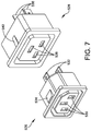
- FIG. 7 illustrates a first outlet 526 and a second outlet 528.
- the first outlet 526 is a C13 type outlet and includes female receptacle openings 530 to mate with a C14 type plug, male mating terminals 532 to mate with an outlet board such as the outlet board 510, and a locking mechanism 534.
- the second outlet 528 is a C19 type outlet and includes female receptacle openings 536 to mate with a C20 type plug, male mating terminals 538 to mate with an outlet board such as the outlet board 510, and a locking mechanism 540.
- the male mating terminals 532 and the male mating terminals 538 are 0.250 in. male FASTON tabs.
- the locking mechanism 534 and the locking mechanism 540 each may be embodied as a tapered, spring-loaded snap-in tab. This design permits the first outlet 526 and the second outlet 528, respectively, to be easily inserted into a corresponding one of the outlet openings, but prevents the first outlet 526 and the second outlet 528 from becoming easily dislodged.
- FIG. 8 illustrates the faceplate 504 with the outlets 506, including the first outlet 526 and the second outlet 528, snapped into outlet openings on the front surface portion 515 of the faceplate 504.
- the locking mechanism 534 and the locking mechanism 540 are not accessible from the outside of the faceplate 504, thereby preventing the outlets from becoming easily dislodged.
- alternate fastening mechanisms may be used.
- the first outlet 526 and the second outlet 528 may be attached to the faceplate 504 using one or more threaded fasteners, permanently affixed using an adhesive material, or attached to the faceplate 504 using another method of attachment.
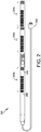
- the flexible and configurable outlet board 510 hereinafter referred to as the outlet board 510, will now be described in greater detail with respect to FIG. 9 .
- the outlet board 510 includes several bank jumpers, each indicated at 542, several AC line input tabs, each indicated at 544, and several groups of female outlet board terminals, including a group of female outlet board terminals indicated at 546.
- the bank jumpers 542 are used to configure the outlet module 502c.
- the bank jumpers 542 can be used to split the eight depicted outlets into four banks of two outlets each, two banks of four outlets each, or one bank of eight outlets.
- the AC line input tabs 544 are 0.250 in. male FASTON tabs configured to couple to, and receive AC line input from, corresponding female terminals on the control board 508.
- the group of female terminals 546 includes two sets of three female terminals, with a first set being configured to receive a first type of mating tab (e.g., the male mating terminals 532 of the first outlet 526) and a second set configured to receive a second type of mating tab (e.g., the male mating terminals 538 of the second outlet 528).
- FIG. 10 illustrates a more detailed view of the group of female outlet board terminals 546 including the first set of three female terminals and the second set of three female terminals.
- the first set of three female terminals includes an AC line connection 548a, a neutral/AC line two connection 550a, and an earth ground connection 552a.
- the second set of three female terminals includes an AC line connection 548b, a neutral/AC line two connection 550b, and an earth ground connection 552b.
- the outlet board 510 also includes clearance slots 554 to receive C19 type outlet male FASTON tabs or outlet housing features.
- each pair of female terminals 548-552 Only one connection of each pair of female terminals 548-552 will be mechanically engaged at any one point in time, depending on which type of outlet is connected to the group of female outlet board terminals. For example, if a C19 type outlet is mated with the group of female outlet board terminals 546, the outlet's male tabs will mate with the first set of three female terminals including the AC line connection 548a, the neutral/AC line two connection 550a, and the earth ground connection 552a.
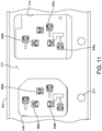
- FIG. 11 illustrates a top view of several groups of female outlet board terminals, in combination with the first outlet opening 516 and the second outlet opening 518.
- the PCB upon which the several groups of female outlet board terminals are mounted is not shown, and the first outlet 526 and the second outlet 528 have been omitted.
- FIG. 12A illustrates a back perspective view of the first outlet 526 mechanically engaged with the AC line connection 548b, the neutral/AC line two connection 550b, and the earth ground connection 552b for further illustration of the principles discussed above.
- FIG. 12B illustrates a back perspective view of the second outlet 528 mechanically engaged with the AC line connection 548a, the neutral/AC line two connection 550a, and the earth ground connection 552a for further illustration of the principles discussed above.
- the outlet board 510 is configured to mate with multiple types of outlets, such as C13 and C19 type outlets, regardless of the number and arrangement of the multiple types of outlets, because each group of female outlet board terminals is designed to mate with either a C13 or C19 type outlet.
- FIG. 13 illustrates a bottom perspective view of the faceplate 504, the outlets 506, and the outlet board 510 connected together.
- fastener openings such as the fastener opening 524, are provided in the outlet board 510 to receive standoffs to couple the faceplate 504 to the outlet board 510.
- FIG. 13 illustrates a plurality of first hex standoffs 525, a second hex standoff 556, and a third hex standoff 558.
- Each of the plurality of first hex standoffs 525 is configured to be coupled between the faceplate 504 and the outlet board 510.
- the second hex standoff 556 and the third hex standoff 558 are configured to be coupled to respective hex standoffs of the plurality of first hex standoffs 525 at a first end.
- the second hex standoff 556 is coupled to a respective hex standoff of the plurality of first hex standoffs 525 via the fastener opening 524 in the outlet board 510.
- the second hex standoff 556 and the third hex standoff 558 are configured to be coupled to the control board 508 at a second end.
- the second hex standoff 556 and the third hex standoff 558 are 3/16 in. hex standoffs measuring 0.375 in. long to provide electrical bonding for earth ground between the control board 508, the outlet board 510, the plurality of first hex standoffs 525, and the faceplate 504.
- FIG. 13 further illustrates a fourth hex standoff 560 and a fifth hex standoff 562 provided at respective ends of the faceplate 504 to connect the faceplate 504 to the control board 508 as discussed in greater detail below.
- the fourth hex standoff 560 and the fifth hex standoff 562 are 3/16 in. hex standoffs measuring 1.583 in. long to provide electrical bonding for earth ground between the control board 508 and the faceplate 504.
- FIG. 13 further illustrates the AC line input tabs 544, which are configured to receive AC line input from the control board 508.
- the outlet board 510 also includes a neutral/AC line two input tab 564, which is configured to be coupled to a neutral/AC line two input as discussed in greater detail below with respect to FIG. 15 .
- the AC line input tabs 544 and the neutral/AC line two input tab 564 are 0.250 in. FASTON tabs, and are capable of accommodating 3 oz copper traces which support a 12 A supply for C13 type outlets and a 16 A supply for C19 type outlets.
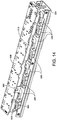
- FIG. 14 illustrates a bottom perspective view of the faceplate 504, the outlets 506, the control board 508, and the outlet board 510 connected together.
- the control board 508 includes an AC line input tab 566 configured to be coupled to an AC line input. As illustrated, the control board 508 includes a notch above the AC line input tab 566 such that the physical footprint of the control board 508 does not obstruct the AC line input tab 566 from being connected to an AC line input.
- the control board 508 is therefore able to receive AC line input power via the AC line input tab 566 and distribute the AC line power to the outlet board 510 via the AC line input tabs 544, which are configured to engage female terminals (not illustrated) affixed to the control board 508.
- the female terminals are FASTON receptacles, similar to the female terminals 546 on the outlet board 510.
- the control board 508 includes a notch above the neutral/AC line two input tab 564 such that the physical footprint of the control board 508 does not obstruct the neutral/AC line two input tab 564 from being connected to a neutral/AC line two input.
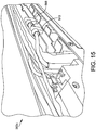
- FIG. 15 illustrates a bottom perspective view of the outlet module 502c.
- the outlet module 502c is configured to connect to, and receive AC power from, an AC line input 568 connected to the AC line input tab 566, and a neutral/AC line two input 570 connected to the neutral/AC line two input tab 564.
- the AC line input 568 and the neutral/AC line two input 570 receive AC power from AC power provided to the rPDU 500 via the plug 512.
- the wiring arrangement connected to the outlet module 502c is significantly more organized than the wiring arrangement illustrated in FIG. 3 , thereby making maintenance and troubleshooting of the outlet module 502c significantly more convenient.
- the rPDU 500 has been illustrated as having one row of three outlet modules 502a-502c, it is to be appreciated that the rPDU 500 may include any number of outlet modules arranged in any number of rows.
- an rPDU constructed according to the foregoing disclosure could be configured to include seven outlet modules for a total of 56 outlets, arranged in two rows.
- a user's available space for the rPDU may be the only limit on the size of the rPDU.
- the rPDU 500 measures approximately 72 in. x 2.185 in., not including the length of the plug 512 and the wire attached thereto.
- C13 and C19 type outlets alternate types of outlets are similarly within the scope of the present disclosure.
- the embodiments discussed above can support C15 and C21 type outlets, which are high-temperature variants of the C13 and C19 type outlets, respectively.
- Burland C13 and C19 type outlets may also be supported where the outlets are provided with a corresponding outlet PCB and a deeper outlet chassis to support the size of the outlets.
- Alternate embodiments can also support NEMA 5-15R and 5-20R type outlets where the outlets are provided with a corresponding outlet PCB that includes female terminals arranged to receive the NEMA 5-15R and 5-20R type outlet male FASTON tabs. Any number (e.g., more or less than two) and type (e.g. NEMA 5-15R, C13, etc.) of outlets may be combined using the principles discussed herein.
- the faceplate 504 includes several outlet openings capable of receiving outlets of two types.
- outlet opening shapes can be stamped into the faceplate 504 to enable the first outlet opening 516 to receive a first type of outlet, and the second outlet opening 518 to receive a second type of outlet, enabling up to 256 different outlet combination arrangements.
- FIG. 16 illustrates an outlet module faceplate 1600 according to another embodiment.
- the outlet module faceplate 1600 includes several uniform outlet openings, each indicated at 1602.
- Each outlet opening 1602 is configured to receive either a first outlet of a first type or an outlet adapter configured to adapt the shape of a second outlet of a second type to the shape of the first outlet of the first type.
- each of the uniform outlet openings 1602 can be configured to receive either a C19 type outlet or an outlet adapter configured to adapt the shape of a C13 type outlet to the shape of the C19 type outlet.
- Each of the uniform outlet openings 1602 can measure 29.50 mm x 38.20 mm (+0.1 mm/-0.0 mm), consistent with the requirements for mounting a standard C19 panel mounted outlet.
- FIG. 17 illustrates an outlet adapter generally indicated at 1604 configured to adapt the shape of the first outlet 526 of the first type to the shape of an outlet opening 1602 (e.g., a C19 type outlet opening) of the outlet module faceplate 1600.
- the outlet adapter 1604 includes a body 1606 having a cavity 1608 to receive the first outlet 526, a lip 1609 disposed along an upper edge of the body 1606 to prevent the outlet adapter 1604 from passing beyond a face of the outlet opening 1602, and a shelf 1610 to prevent the first outlet 526 from passing beyond a face of the outlet adapter 1604.
- the outlet adapter 1604 further includes a V-lock opening 1612 to receive a retaining cord operable to prevent the retaining cord from becoming dislodged from the first outlet 526, a locking mechanism 1614 to retain the outlet adapter 1604 in the outlet opening 1602, and an opening 1616 to receive an outlet locking mechanism (e.g., the locking mechanism 534) to prevent the first outlet 526 from becoming dislodged from the cavity 1608.
- a V-lock opening 1612 to receive a retaining cord operable to prevent the retaining cord from becoming dislodged from the first outlet 526
- a locking mechanism 1614 to retain the outlet adapter 1604 in the outlet opening 1602
- an opening 1616 to receive an outlet locking mechanism (e.g., the locking mechanism 534) to prevent the first outlet 526 from becoming dislodged from the cavity 1608.
- the outlet adapter 1604 is constructed from Underwriters Laboratories (UL)-approved Nylon 6 material, is filled approximately 20% with glass, and has a V-2 flammability rating.
- the physical profile of the outlet adapter 1604 can be constructed to fit into a corresponding outlet opening.
- the outlet opening can be a 29.50 mm x 38.20 mm opening configured to receive a C19 type outlet.
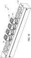
- FIG. 18 illustrates a bank of outlets 1618 including the first outlet 526 of the first type in combination with the outlet adapter 1604, and the second outlet 528 of the second type, fitted into uniform outlet openings of the outlet module faceplate 1600. Because the outlet module faceplate 1600 may be manufactured and stamped without any knowledge of customer requirements, the manufacturing process may be streamlined significantly.
- FIG. 19 illustrates an outlet adapter 1900 configured to adapt a NEMA 5-20R type outlet to a C19 type outlet opening, alongside the outlet adapter 1604.
- An rPDU having modular components which can be configured and assembled downstream from a manufacturing facility allow more flexible solutions and a faster turn-around time to customer specifications, enabling a leaner manufacturing process.
- outlet adapters can be employed to enable outlets to adapt to variously-sized outlet openings.
Landscapes
- Engineering & Computer Science (AREA)
- Microelectronics & Electronic Packaging (AREA)
- Computer Hardware Design (AREA)
- General Engineering & Computer Science (AREA)
- Connector Housings Or Holding Contact Members (AREA)
- Details Of Connecting Devices For Male And Female Coupling (AREA)
Abstract
Description
- Aspects and embodiments of the present invention are directed generally to electronic equipment mounting racks, and more specifically, to power distribution units contained therein.
- In response to the increasing demands of information-based economies, information technology networks continue to proliferate across the globe. One manifestation of this growth is the centralized network data center. A centralized network data center typically consists of various information technology equipment, co-located in a structure that provides network connectivity, electrical power, and cooling capacity. Often the equipment is housed in specialized enclosures termed "racks" which integrate these connectivity, power and cooling elements.
- Equipment racks may include power distribution and wire management systems coupled to the racks to supply power and communication lines to the equipment in the racks. A type of power distribution system often used in electronic equipment racks, referred to as a "Rack Power Distribution Unit" or "rPDU," includes multiple electrical outlets of the same or different specification for supplying power to equipment in a rack. One or more rPDUs may be mounted, for example, on one or both sides of the rear of a rack.
- According to one aspect of the present invention a rack power distribution unit is provided having one or more outlet modules. Each outlet module includes a body or faceplate having a plurality of outlet openings. A plurality of outlets are configured to be inserted into, and retained within, the plurality of outlet openings. An outlet board (e.g., an Outlet Printed Circuit Board [PCB] assembly) herein referred to as an outlet board, is configured to be coupled to, and distribute power to, the plurality of outlets. A control board (e.g., a control Printed Circuit Board [PCB] assembly) herein referred to as a control board, is configured to be coupled to, and distribute power to, the outlet board, where the outlet board is configured to be coupled to a first outlet of a first type and a second outlet of a second type, and where the outlet board includes a plurality of groups of female outlet board terminals, each group of female outlet board terminals being associated with a respective outlet of the plurality of outlets, and including a first set of female outlet board terminals configured to be coupled to the first outlet of the first type, and a second set of female outlet board terminals configured to be coupled to the second outlet of the second type, the second set of female outlet board terminals being different than the first set of female outlet board terminals.
- The plurality of outlet openings may configured to accommodate at least 256 different configurations of outlet openings. The plurality of outlet receptacles may include an IEC320-C13 type outlet and an IEC320-C19 type outlet, otherwise referred to as C13 type outlet and C19 type outlet respectfully. The plurality of outlet openings may include a first outlet opening configured to receive the C13 type outlet, and a second outlet opening configured to receive the C19 type outlet. Each outlet of the plurality of outlets types may include a locking tab configured to allow a respective outlet to be inserted into a respective outlet opening of the plurality of outlet openings and to prevent the respective outlet from being removed from the respective outlet opening of the outlet module.
- In some embodiments, an outlet adapter may be provided and is configured to be inserted into, and retained within, a respective outlet opening of the plurality of outlet openings. The outlet adapter may be configured to enable the first outlet of the first type to be inserted into an outlet opening of the plurality of outlet openings configured to receive the second outlet of the second type. The outlet adapter may include a locking tab configured to allow the adapter to be inserted into a respective outlet opening of the plurality of outlet openings and prevent the adapter from being removed from the respective outlet opening. Each of the plurality of outlet openings may be substantially identical in size, and each outlet opening of the plurality of outlet openings may be configured to receive one of the outlet adapters and the second outlet of the second type. One or more outlet modules may include a plurality of rows of outlets.
- Another aspect of the disclosure is directed to a rack power distribution unit including at least one outlet module. The at least one outlet module may include a body. The body may include a plurality of outlets. The at least one outlet module may include means for receiving, and retaining, the plurality of outlets, and means for distributing power received from a power source to the plurality of outlets. The means for distributing power may be configured to be coupled to a first outlet of a first type and a second outlet of a second type._The means for distributing power may include a plurality of groups of female outlet board terminals, each group of female outlet board terminals being associated with a respective outlet of the plurality of outlets, and including a first set of female outlet board terminals configured to be coupled to the first outlet of the first type, and a second set of female outlet board terminals configured to be coupled to the second outlet of the second type, the second set of female outlet board terminals being different than the first set of female outlet board terminals
- The plurality of outlets may include a C13 type outlet and a C19 type outlet. The means for receiving, and retaining, the plurality of outlets may include means for receiving and retaining the C13 type outlet, and means for receiving and retaining the C19 type outlet. Each outlet of the plurality of outlets may include a locking tab configured, in combination with the means for receiving and retaining the plurality of outlets, to allow a respective outlet to be received by the means for receiving and retaining the plurality of outlets and to prevent the respective outlet from being removed from the means for receiving and retaining the plurality of outlets. The means for receiving and retaining the plurality of outlets may include means for receiving and retaining an outlet of the first type, further comprising means for adapting an outlet of the second type to be received and retained by the means for receiving and retaining the outlet of the first type.
- The outlet of the first type may be a C19 type outlet, and the outlet of the second type may be a C13 type outlet. The means for adapting an outlet of the second type to be received and retained by the means for receiving and retaining the outlet of the first type may include means for allowing the means for adapting an outlet of the second type to be received and retained by the means for receiving and retaining the outlet of the first type to be inserted into the means for receiving, and retaining, the plurality of outlets and for preventing the means for adapting an outlet of the second type to be received and retained by the means for receiving and retaining the outlet of the first type from being removed from the means for receiving, and retaining, the plurality of outlets. The at least one outlet module may include a plurality of rows of outlets.
- Another aspect of the disclosure is directed to an outlet adapter to enable an outlet of a first type to be inserted into an outlet opening configured to receive an outlet of a second type. The outlet adapter may include a body constructed to be inserted into the outlet opening configured to receive the outlet of the second type, and having a lip to prevent the outlet adapter from passing through the outlet opening. The outlet adapter may further include a first cavity formed in the body to receive the outlet of the first type. The outlet adapter may further include a first locking tab to allow the outlet adapter to be inserted into the outlet opening and prevent the outlet adapter from being removed from the outlet opening. The outlet adapter may further a second cavity that allows a second locking tab of the outlet of the first type to be inserted into the first cavity to prevent the outlet of the first type from being removed from the first cavity. The outlet adapter may be configured to receive a C13 type outlet or a 5-20R type outlet, and the body may be configured to be inserted into an outlet opening configured to receive a C19 type outlet.
- Another aspect of the disclosure is directed to a method of constructing a rack power distribution unit including a main body. The method can include receiving, from a manufacturer, an outlet module faceplate. The method can further include receiving, from a customer, outlet arrangement specifications. The method can further include stamping, responsive to receiving the outlet arrangement specifications, a plurality of outlet openings in the outlet module faceplate. The method can further include inserting a respective outlet of a plurality of outlets into each outlet opening of the plurality of outlet openings. The method can further include coupling an outlet board to the plurality of outlets. The method can further include coupling the control board to an outlet board. The method can further include coupling the outlet module to the main body of the rack power distribution unit.
- The accompanying drawings are not intended to be drawn to scale. In the drawings, each identical or nearly identical component that is illustrated in various figures is represented by a like numeral. For purposes of clarity, not every component may be labeled in every drawing. In the drawings:
-
FIG. 1 illustrates a rear view of an electronic equipment rack; -
FIG. 2 illustrates a top view of a conventional rack Power Distribution Unit (rPDU); -
FIG. 3 illustrates a perspective inside view of a portion of the conventional rPDU; -
FIG. 4 illustrates a top view of a conventional rPDU according to another example; -
FIG. 5A illustrates a top view of an rPDU according to one embodiment; -
FIG. 5B illustrates a perspective view of an rPDU outlet module according to one embodiment; -
FIG. 5C illustrates a bottom perspective view of the rPDU outlet module according to one embodiment; -
FIG. 6 illustrates a perspective view of an outlet module faceplate according to one embodiment; -
FIG. 7 illustrates a perspective view of a first outlet and a second outlet according to one embodiment; -
FIG. 8 illustrates a perspective view of the outlet module faceplate in combination with the outlets according to one embodiment; -
FIG. 9 illustrates a perspective view of an outlet board according to one embodiment; -
FIG. 10 illustrates a detailed view of outlet board female terminals according to one embodiment; -
FIG. 11 illustrates a top view of outlet openings and groups of outlet board female terminals according to one embodiment; -
FIG. 12A illustrates a bottom perspective view of a portion of an outlet of a first type coupled to a group of outlet board female terminals according to one embodiment; -
FIG. 12B illustrates a bottom perspective view of a portion of an outlet of a second type coupled to a group of outlet board female terminals according to one embodiment; -
FIG. 13 illustrates a bottom perspective view of the outlet module, several outlets, and the outlet board according to one embodiment; -
FIG. 14 illustrates a bottom perspective view of the outlet module, the outlets, the outlet board, and the control board according to one embodiment; -
FIG. 15 illustrates a bottom perspective view of a portion of the rack Power Distribution Unit (rPDU) including the outlet module with routed electrical harnessing according to one embodiment; -
FIG. 16 illustrates a top view of an outlet module faceplate according to one embodiment; -
FIG. 17 illustrates a perspective view of an outlet, an outlet adapter, and the outlet module faceplate according to one embodiment; -
FIG. 18 illustrates a perspective view of a portion of the outlet module faceplate in combination with outlet adapters and outlets according to one embodiment; and -
FIG. 19 illustrates outlets fitted in respective outlet adapters according to one embodiment. - Embodiments of the present disclosure are directed generally to a flexible and configurable rack Power Distribution Unit (rPDU) capable of providing power via outlets of the same or a different type arranged according to any configuration. The flexible and configurable rPDU can be easily adapted to customer specifications identifying an arrangement of outlet types, and provides significant reductions in fabrication time, complexity, and cost.
- Examples of the methods and systems discussed herein are not limited in application to the details of construction and the arrangement of components set forth in the following description or illustrated in the accompanying drawings. The methods and systems are capable of implementation in other embodiments and of being practiced or of being carried out in various ways. Examples of specific implementations are provided herein for illustrative purposes only and are not intended to be limiting. In particular, acts, components, elements and features discussed in connection with any one or more examples are not intended to be excluded from a similar role in any other examples.
- Also, the phraseology and terminology used herein is for the purpose of description and should not be regarded as limiting. Any references to examples, embodiments, components, elements or acts of the systems and methods herein referred to in the singular may also embrace embodiments including a plurality, and any references in plural to any embodiment, component, element or act herein may also embrace embodiments including only a singularity. References in the singular or plural form are not intended to limit the presently disclosed systems or methods, their components, acts, or elements. The use herein of "including," "comprising," "having," "containing," "involving," and variations thereof is meant to encompass the items listed thereafter and equivalents thereof as well as additional items. References to "or" may be construed as inclusive so that any terms described using "or" may indicate any of a single, more than one, and all of the described terms. In addition, in the event of inconsistent usages of terms between this document and documents incorporated herein by reference, the term usage in the incorporated references is supplementary to that of this document; for irreconcilable inconsistencies, the term usage in this document controls.
- A simplified rear view of an electronic equipment rack (also referred to herein simply as a "rack") is illustrated in
FIG. 1 , generally at 100. The doors of therack 100 are omitted fromFIG. 1 for clarity. The rack may include drawer enclosures, each respectively indicated at 120, including items that support power and/or network connections for other equipment mounted in the rack. Uninterruptible Power Supplies (UPSs), each indicated at 140, may be installed as rack mounted devices to increase the power supply redundancy of the rack. Therack 100 may include computing or network technology equipment, for example, one or more data storage devices, each indicated at 150, aserver 160, apatch panel 170, akeyboard tray 180, acable organizer 190, and/or a monitor or other user interface which may provide for an operator to communicate with the equipment in the rack. The rack may be configured in any manner desired by the end user. - An
rPDU 110 may be mounted internal to therack 100. TherPDU 110 may be vertically mounted, as illustrated inFIG. 1 , or may be horizontally mounted in the rack along with the other equipment in the rack. Although onerPDU 110 is shown and described, two or more rPDU's may be provided in the rack. TherPDU 110 may receive power from theUPSs 140 in the rack, or directly from an AC utility supply, and may include power outlets to which power cords from the various other equipment in the rack may be electrically connected. - The
rPDU 110 may include outlets of a single type, or of varied types, configured to receive a plug of a corresponding type. As will be understood by one of ordinary skill in the art, International Electrotechnical Commission (IEC) 60320 defines a set of standards for general-purpose plug-and-outlet pairs. For example, the IEC 320-C19/C20 standard identifies an outlet and a plug, respectively, typically employed in higher-current applications, such as in providing power to a UPS. A first conventional embodiment of therPDU 110 is illustrated below with respect toFIGS. 2 and3 , and a second conventional embodiment of therPDU 110 is illustrated below with respect toFIG. 4 . -
FIG. 2 illustrates one example of anrPDU 200 including outlets of varied types. TherPDU 200 includes aplug 202 andseveral outlet banks 204a-204c. Each outlet bank of theoutlet banks 204a-204c includes a total of eight outlets in one of two types. For example, afirst outlet bank 204a includes afirst outlet 206 of a first type, and asecond outlet 208 of a second type. As will be understood by one of ordinary skill in the art, thefirst outlet 206 is defined by IEC 60320 as an IEC 320-C13 outlet (hereinafter, a C13 type outlet) configured to receive an IEC 320-C14 plug (hereinafter, a C14 type plug), and thesecond outlet 208 is defined by IEC 60320 as an IEC 320-C19 outlet (hereinafter a C19 type outlet) configured to receive an IEC 320-C20 plug (hereinafter a C20 type plug). In normal operation, therPDU 200 is configured to receive power via theplug 202 which is connected, for example, to an AC mains power supply or to a UPS, such as theUPS 140 provided in therack 100. The power received via theplug 202 is distributed to each outlet in theoutlet banks 204a-204c to provide power to devices connected thereto (not illustrated). - Each outlet bank of the
outlet banks 204a-204c may be subject to certain specifications or requirements. For example, there may be minimum spacing requirements between outlets as a function of the outlet type. A minimum center-to-center (CTC) spacing between two outlets of the same type may be different than a minimum CTC spacing between two outlets of different types. For example, a minimum CTC between two C13 type outlets, such as two adjacent C13 type outlets in thefirst outlet bank 204a, may be 1.4 in., whereas a larger minimum CTC may exist between a C13 type outlet and a C19 type outlet (e.g., a 1.6 in. minimum CTC distance). Accordingly, it may be difficult to replace a C13 type outlet with a C19 type outlet without violating certain design specifications or requirements because there may not be enough physical space to accommodate the C19 type outlet. -
FIG. 3 illustrates an inside view of thefirst outlet bank 204a. As illustrated byFIG. 3 , several wires are required to route power to thefirst outlet banks 204a, and to route control signals between thefirst outlet bank 204a and a control board (e.g., a PCB). As illustrated byFIG. 3 , organizing the arrangement of the wires may be challenging. - The
first outlet 206 of the first type (e.g., a C13 type outlet) includes aback cap 210 affixed to the back of thefirst outlet 206 to prevent dislodging of wires from their Insulation Displacement Connection (IDC) terminals and to prevent live connections from being exposed. However, as illustrated by asecond outlet 212 of the first type (e.g., a C13 type outlet), the back cap may become inadvertently dislodged or removed, causing inadvertent dislodging of wires or exposure of the live connections of thesecond outlet 212. -
FIG. 4 illustrates another example of an rPDU, generally indicated at 400, including outlets of varied types. TherPDU 400 includes astrain relief 402 andseveral outlet banks 404a-404c, arranged in two rows. For example, a first row of afirst outlet bank 404a includes afirst outlet 406 of a first type (i.e., a C19 type outlet) and a second row of thefirst outlet bank 404a includes asecond outlet 408 of a second type (i.e., a C13 type outlet). TherPDU 400 may be referred to as a "double wide chassis" by virtue of having two rows of outlets, whereas therPDU 200 described above with respect toFIGS. 2 and3 may be referred to as a "single wide chassis" by virtue of having a single row of outlets. TherPDU 400 adds flexibility relative to therPDU 200 because, by segregating outlet types by row, outlets of a specific type may be added or removed from a corresponding row without the concern of violating CTC requirements between two outlets of different types. - However, similar to the
rPDU 200, back caps affixed to certain types of outlets (e.g., C13 type outlets) in theoutlet banks 404a-404c may become dislodged or removed, and arranging and organizing wires in an orderly fashion may be challenging. Moreover, both therPDU 200 andrPDU 400 are constrained by a requirement that the outlets of therPDUs -
FIG. 5A illustrates a top view of anrPDU 500 including aplug 512 and several flexible andconfigurable outlet modules 502a-502c according to an embodiment. TherPDU 500 is configured to receive AC power via theplug 512 and distribute the AC power via the flexible andconfigurable outlet modules 502a-502c. Each of the flexible andconfigurable outlet modules 502a-502c includes a bank of eight outlets in one of two types, where the arrangement of the outlets may be specified by a customer. - For purposes of clarity, operation of the flexible and
configurable outlet modules 502a-502c will be described with reference to the flexible andconfigurable outlet module 502c. However, it is to be appreciated that the principles described with reference to the flexible andconfigurable outlet module 502c are similarly applicable to the flexible andconfigurable outlet module 502a and to the flexible andconfigurable outlet module 502b. -
FIG. 5B illustrates a top perspective view of the flexible andconfigurable outlet module 502c, hereinafter referred to asoutlet module 502c, according to an embodiment. Theoutlet module 502c can be produced with several modular components to addresses the foregoing concerns. Theoutlet module 502c includes afaceplate 504,several outlets 506, and a flexible andconfigurable control board 508.FIG. 5C illustrates a bottom perspective view of theoutlet module 502c, including thefaceplate 504, theoutlets 506, the flexible andconfigurable control board 508, and a flexible andconfigurable outlet board 510. - The
faceplate 504 retains components of theoutlet module 502c and is discussed in greater detail below with respect toFIG. 6 . Thefaceplate 504 may be manufactured with a specific configuration arrangement of outlet openings stamped thereon according to customer specifications, and shipped in a configured state to a distribution center. In alternate embodiments, the outlet openings may be manufactured using alternate methods. For example, the outlet openings may be laser cut into thefaceplate 504. - Each of the
outlets 506 includes a first end having female terminals designed to mate with a corresponding plug, and a second end having male terminals configured to mate with corresponding female terminals on theoutlet board 510 from which to receive power, as discussed in greater detail below with respect toFIG. 7 . Each of theoutlets 506 is configured to be inserted into a corresponding opening stamped into thefaceplate 504, and to lock into position to avoid becoming dislodged from the corresponding opening. - In one embodiment, the flexible and
configurable outlet board 510 is a PCB Assembly (PCBA) configured to mate with theoutlets 506 and facilitate power distribution thereto, and is described in greater detail below with respect toFIG. 9 . The flexible andconfigurable outlet board 510 is configured to mate with outlets having varied types in any arrangement (e.g., C13 and C19 type outlets arranged according to any permutation) without having any knowledge of the arrangement. - In one embodiment, the flexible and
configurable control board 508 is a PCBA configured to mate with the flexible andconfigurable outlet board 510, and is described in greater detail below with respect toFIG. 14 . The flexible andconfigurable control board 508 is configured to receive AC line potential power and distribute the AC line potential power to theoutlets 506 via the flexible andconfigurable outlet board 510. - The
faceplate 504 will now be described in greater detail with reference toFIG. 6 . Thefaceplate 504 includes abody 514 having afront surface portion 515 andflanges 517. Thefront surface portion 515 includes several outlet openings including afirst outlet opening 516 and asecond opening 518 stamped into thefront surface portion 515, several light pipes including alight pipe 522, and several fastener openings including afastener opening 524. Theflanges 517 include several fastener openings including afastener opening 520. - Each outlet opening is configured to receive an outlet. The outlet openings are stamped into the
front surface portion 515 in a shape selected to receive a specific type of outlet. For example, the first outlet opening 516 can receive a C13 type outlet, and the second outlet opening 518 can receive a C19 type outlet. The outlets may include a locking mechanism that secures the outlet into a respective outlet opening of the outlet openings, such that the outlet is not inadvertently removed or dislodged from a respective outlet opening. - As discussed above, the
faceplate 504 may be received by a distributor from a manufacturer with the outlet openings stamped into thefaceplate 504. A customer order may include a specific arrangement of outlet openings provided to a manufacturer, and the manufacturer manufactures thefaceplate 504 having the outlet openings stamped into thefaceplate 504 according to the customer order. The configuredfaceplate 504 is subsequently sent to the distributor. - In one example, the
faceplate 504 may be constructed of 18 Ga cold rolled steel, measuring 2.185 in. x 13.425 in., and may support 1.6 in. CTC spacing for a bank of eight outlets. For a bank of eight outlets, up to 256 different permutations of outlet configurations are possible where two different types of outlets are available. - The
fastener opening 520 is configured to receive a fastener, such as a female threaded fastener, to affix thefaceplate 504 to a chassis of therPDU 500. Additionally, the female threaded fastener provides electrical bonding for earth ground between the chassis of therPDU 500 and theoutlet module 502c. Thelight pipe 522 is used to display a visual status indicator of a corresponding status of the outlet. For example, thelight pipe 522 corresponds to thefirst outlet opening 516 and may indicate whether an outlet secured in the first outlet opening 516 is energized to provide electrical power. Thelight pipe 522 may be connected to a Light-Emitting Diode (LED) configured to emit light (e.g., a green light) when power is available from an outlet secured in the first outlet opening, and to not emit light when power is unavailable from the outlet secured in the first outlet opening. In some embodiments, thelight pipe 522 may be omitted during the manufacturing process depending on customer requirements. - The
fastener opening 524 is configured to receive a male threaded fastener, which may be configured to receive a standoff. In one example, the male threaded fastener may be configured to receive a 3/16 in. hex standoff fastener measuring 1.11 in. long. In addition to securing theoutlet board 510 to thefaceplate 504, the standoffs provide electrical bonding for earth ground between thefaceplate 504, theoutlet board 510, and outlets secured in the outlet openings. - The
outlets 506 will now be described in greater detail with respect toFIG. 7. FIG. 7 illustrates afirst outlet 526 and asecond outlet 528. Thefirst outlet 526 is a C13 type outlet and includesfemale receptacle openings 530 to mate with a C14 type plug,male mating terminals 532 to mate with an outlet board such as theoutlet board 510, and alocking mechanism 534. Thesecond outlet 528 is a C19 type outlet and includesfemale receptacle openings 536 to mate with a C20 type plug,male mating terminals 538 to mate with an outlet board such as theoutlet board 510, and alocking mechanism 540. In one example, themale mating terminals 532 and themale mating terminals 538 are 0.250 in. male FASTON tabs. - In the embodiment illustrated by
FIG. 7 , thelocking mechanism 534 and thelocking mechanism 540 each may be embodied as a tapered, spring-loaded snap-in tab. This design permits thefirst outlet 526 and thesecond outlet 528, respectively, to be easily inserted into a corresponding one of the outlet openings, but prevents thefirst outlet 526 and thesecond outlet 528 from becoming easily dislodged. -
FIG. 8 illustrates thefaceplate 504 with theoutlets 506, including thefirst outlet 526 and thesecond outlet 528, snapped into outlet openings on thefront surface portion 515 of thefaceplate 504. Thelocking mechanism 534 and thelocking mechanism 540 are not accessible from the outside of thefaceplate 504, thereby preventing the outlets from becoming easily dislodged. In other embodiments, however, alternate fastening mechanisms may be used. For example, thefirst outlet 526 and thesecond outlet 528 may be attached to thefaceplate 504 using one or more threaded fasteners, permanently affixed using an adhesive material, or attached to thefaceplate 504 using another method of attachment. - The flexible and
configurable outlet board 510, hereinafter referred to as theoutlet board 510, will now be described in greater detail with respect toFIG. 9 . Theoutlet board 510 includes several bank jumpers, each indicated at 542, several AC line input tabs, each indicated at 544, and several groups of female outlet board terminals, including a group of female outlet board terminals indicated at 546. - The
bank jumpers 542 are used to configure theoutlet module 502c. For example, thebank jumpers 542 can be used to split the eight depicted outlets into four banks of two outlets each, two banks of four outlets each, or one bank of eight outlets. The ACline input tabs 544 are 0.250 in. male FASTON tabs configured to couple to, and receive AC line input from, corresponding female terminals on thecontrol board 508. The group offemale terminals 546 includes two sets of three female terminals, with a first set being configured to receive a first type of mating tab (e.g., themale mating terminals 532 of the first outlet 526) and a second set configured to receive a second type of mating tab (e.g., themale mating terminals 538 of the second outlet 528). -
FIG. 10 illustrates a more detailed view of the group of femaleoutlet board terminals 546 including the first set of three female terminals and the second set of three female terminals. The first set of three female terminals includes anAC line connection 548a, a neutral/AC line twoconnection 550a, and anearth ground connection 552a. The second set of three female terminals includes anAC line connection 548b, a neutral/AC line twoconnection 550b, and anearth ground connection 552b. Theoutlet board 510 also includesclearance slots 554 to receive C19 type outlet male FASTON tabs or outlet housing features. - Only one connection of each pair of female terminals 548-552 will be mechanically engaged at any one point in time, depending on which type of outlet is connected to the group of female outlet board terminals. For example, if a C19 type outlet is mated with the group of female
outlet board terminals 546, the outlet's male tabs will mate with the first set of three female terminals including theAC line connection 548a, the neutral/AC line twoconnection 550a, and theearth ground connection 552a. Conversely, if a C13 type outlet is mated with the group of femaleoutlet board terminals 546, the outlet's male tabs will mate with the second set of three female terminals including theAC line connection 548b, the neutral/AC line twoconnection 550b, and theearth ground connection 552b. -
FIG. 11 illustrates a top view of several groups of female outlet board terminals, in combination with thefirst outlet opening 516 and the second outlet opening 518. For clarity of illustration, the PCB upon which the several groups of female outlet board terminals are mounted is not shown, and thefirst outlet 526 and thesecond outlet 528 have been omitted. - When the first outlet 526 (e.g., a C13 type outlet) is inserted into the
first outlet opening 516, themale mating terminals 532 of thefirst outlet 526 will mechanically engage with theAC line connection 548b, the neutral/AC line twoconnection 550b, and theearth ground connection 552b.FIG. 12A illustrates a back perspective view of thefirst outlet 526 mechanically engaged with theAC line connection 548b, the neutral/AC line twoconnection 550b, and theearth ground connection 552b for further illustration of the principles discussed above. - When the second outlet 528 (e.g., a C19 type outlet) is inserted into the second outlet opening 518, the
male mating terminals 538 of thesecond outlet 528 will mechanically engage theAC line connection 548a, the neutral/AC line twoconnection 550a, and theearth ground connection 552a.FIG. 12B illustrates a back perspective view of thesecond outlet 528 mechanically engaged with theAC line connection 548a, the neutral/AC line twoconnection 550a, and theearth ground connection 552a for further illustration of the principles discussed above. - It is to be appreciated that the
outlet board 510 is configured to mate with multiple types of outlets, such as C13 and C19 type outlets, regardless of the number and arrangement of the multiple types of outlets, because each group of female outlet board terminals is designed to mate with either a C13 or C19 type outlet. This allows a highly flexible system, because theoutlet board 510 is universally applicable to any outlet module (e.g., any one of theoutlet modules 502a-502c) and does not require any customization regardless of the arrangement of the multiple types of outlets. -
FIG. 13 illustrates a bottom perspective view of thefaceplate 504, theoutlets 506, and theoutlet board 510 connected together. As discussed above, fastener openings, such as thefastener opening 524, are provided in theoutlet board 510 to receive standoffs to couple thefaceplate 504 to theoutlet board 510. For example,FIG. 13 illustrates a plurality of firsthex standoffs 525, asecond hex standoff 556, and athird hex standoff 558. - Each of the plurality of first
hex standoffs 525 is configured to be coupled between thefaceplate 504 and theoutlet board 510. Thesecond hex standoff 556 and thethird hex standoff 558 are configured to be coupled to respective hex standoffs of the plurality of firsthex standoffs 525 at a first end. For example, thesecond hex standoff 556 is coupled to a respective hex standoff of the plurality of firsthex standoffs 525 via thefastener opening 524 in theoutlet board 510. Additionally, thesecond hex standoff 556 and thethird hex standoff 558 are configured to be coupled to thecontrol board 508 at a second end. In one example, thesecond hex standoff 556 and thethird hex standoff 558 are 3/16 in. hex standoffs measuring 0.375 in. long to provide electrical bonding for earth ground between thecontrol board 508, theoutlet board 510, the plurality of firsthex standoffs 525, and thefaceplate 504. -
FIG. 13 further illustrates afourth hex standoff 560 and afifth hex standoff 562 provided at respective ends of thefaceplate 504 to connect thefaceplate 504 to thecontrol board 508 as discussed in greater detail below. In one example, thefourth hex standoff 560 and thefifth hex standoff 562 are 3/16 in. hex standoffs measuring 1.583 in. long to provide electrical bonding for earth ground between thecontrol board 508 and thefaceplate 504. -
FIG. 13 further illustrates the ACline input tabs 544, which are configured to receive AC line input from thecontrol board 508. Theoutlet board 510 also includes a neutral/AC line twoinput tab 564, which is configured to be coupled to a neutral/AC line two input as discussed in greater detail below with respect toFIG. 15 . In one embodiment, the ACline input tabs 544 and the neutral/AC line twoinput tab 564 are 0.250 in. FASTON tabs, and are capable of accommodating 3 oz copper traces which support a 12 A supply for C13 type outlets and a 16 A supply for C19 type outlets. -
FIG. 14 illustrates a bottom perspective view of thefaceplate 504, theoutlets 506, thecontrol board 508, and theoutlet board 510 connected together. Thecontrol board 508 includes an ACline input tab 566 configured to be coupled to an AC line input. As illustrated, thecontrol board 508 includes a notch above the ACline input tab 566 such that the physical footprint of thecontrol board 508 does not obstruct the ACline input tab 566 from being connected to an AC line input. Thecontrol board 508 is therefore able to receive AC line input power via the ACline input tab 566 and distribute the AC line power to theoutlet board 510 via the ACline input tabs 544, which are configured to engage female terminals (not illustrated) affixed to thecontrol board 508. In one embodiment, the female terminals are FASTON receptacles, similar to thefemale terminals 546 on theoutlet board 510. Similarly, thecontrol board 508 includes a notch above the neutral/AC line twoinput tab 564 such that the physical footprint of thecontrol board 508 does not obstruct the neutral/AC line twoinput tab 564 from being connected to a neutral/AC line two input. -
FIG. 15 illustrates a bottom perspective view of theoutlet module 502c. Theoutlet module 502c is configured to connect to, and receive AC power from, anAC line input 568 connected to the ACline input tab 566, and a neutral/AC line twoinput 570 connected to the neutral/AC line twoinput tab 564. TheAC line input 568 and the neutral/AC line twoinput 570, in turn, receive AC power from AC power provided to therPDU 500 via theplug 512. As illustrated byFIG. 15 , the wiring arrangement connected to theoutlet module 502c is significantly more organized than the wiring arrangement illustrated inFIG. 3 , thereby making maintenance and troubleshooting of theoutlet module 502c significantly more convenient. - Although the foregoing discussion has been directed primarily to the
outlet module 502c, it is to be appreciated that the principles discussed herein are similarly applicable to theoutlet module 502a and theoutlet module 502b. Moreover, although therPDU 500 has been illustrated as having one row of threeoutlet modules 502a-502c, it is to be appreciated that therPDU 500 may include any number of outlet modules arranged in any number of rows. For example, in one alternate embodiment, an rPDU constructed according to the foregoing disclosure could be configured to include seven outlet modules for a total of 56 outlets, arranged in two rows. A user's available space for the rPDU may be the only limit on the size of the rPDU. In one example, therPDU 500 measures approximately 72 in. x 2.185 in., not including the length of theplug 512 and the wire attached thereto. - Although the foregoing discussion has made reference to C13 and C19 type outlets, alternate types of outlets are similarly within the scope of the present disclosure. For example, the embodiments discussed above can support C15 and C21 type outlets, which are high-temperature variants of the C13 and C19 type outlets, respectively. Burland C13 and C19 type outlets may also be supported where the outlets are provided with a corresponding outlet PCB and a deeper outlet chassis to support the size of the outlets.
- Alternate embodiments can also support NEMA 5-15R and 5-20R type outlets where the outlets are provided with a corresponding outlet PCB that includes female terminals arranged to receive the NEMA 5-15R and 5-20R type outlet male FASTON tabs. Any number (e.g., more or less than two) and type (e.g. NEMA 5-15R, C13, etc.) of outlets may be combined using the principles discussed herein.
- Furthermore, alternate embodiments are contemplated which utilize uniform outlet openings. As discussed above with respect to
FIG. 6 , thefaceplate 504 includes several outlet openings capable of receiving outlets of two types. For example, outlet opening shapes can be stamped into thefaceplate 504 to enable the first outlet opening 516 to receive a first type of outlet, and the second outlet opening 518 to receive a second type of outlet, enabling up to 256 different outlet combination arrangements. -
FIG. 16 illustrates anoutlet module faceplate 1600 according to another embodiment. Theoutlet module faceplate 1600 includes several uniform outlet openings, each indicated at 1602. Eachoutlet opening 1602 is configured to receive either a first outlet of a first type or an outlet adapter configured to adapt the shape of a second outlet of a second type to the shape of the first outlet of the first type. - For example, each of the
uniform outlet openings 1602 can be configured to receive either a C19 type outlet or an outlet adapter configured to adapt the shape of a C13 type outlet to the shape of the C19 type outlet. Each of theuniform outlet openings 1602 can measure 29.50 mm x 38.20 mm (+0.1 mm/-0.0 mm), consistent with the requirements for mounting a standard C19 panel mounted outlet. -
FIG. 17 illustrates an outlet adapter generally indicated at 1604 configured to adapt the shape of thefirst outlet 526 of the first type to the shape of an outlet opening 1602 (e.g., a C19 type outlet opening) of theoutlet module faceplate 1600. Theoutlet adapter 1604 includes abody 1606 having acavity 1608 to receive thefirst outlet 526, alip 1609 disposed along an upper edge of thebody 1606 to prevent theoutlet adapter 1604 from passing beyond a face of theoutlet opening 1602, and ashelf 1610 to prevent thefirst outlet 526 from passing beyond a face of theoutlet adapter 1604. - The
outlet adapter 1604 further includes a V-lock opening 1612 to receive a retaining cord operable to prevent the retaining cord from becoming dislodged from thefirst outlet 526, alocking mechanism 1614 to retain theoutlet adapter 1604 in theoutlet opening 1602, and anopening 1616 to receive an outlet locking mechanism (e.g., the locking mechanism 534) to prevent thefirst outlet 526 from becoming dislodged from thecavity 1608. - In one example, the
outlet adapter 1604 is constructed from Underwriters Laboratories (UL)-approved Nylon 6 material, is filled approximately 20% with glass, and has a V-2 flammability rating. The physical profile of theoutlet adapter 1604 can be constructed to fit into a corresponding outlet opening. For example, in one embodiment, the outlet opening can be a 29.50 mm x 38.20 mm opening configured to receive a C19 type outlet. -
FIG. 18 illustrates a bank ofoutlets 1618 including thefirst outlet 526 of the first type in combination with theoutlet adapter 1604, and thesecond outlet 528 of the second type, fitted into uniform outlet openings of theoutlet module faceplate 1600. Because theoutlet module faceplate 1600 may be manufactured and stamped without any knowledge of customer requirements, the manufacturing process may be streamlined significantly. - Furthermore, although the
outlet adapter 1604 discussed above is configured to adapt a C13 type outlet to a C19 type outlet opening, alternate adapters are similarly contemplated which adapt any one outlet type to any other outlet type. For example,FIG. 19 illustrates anoutlet adapter 1900 configured to adapt a NEMA 5-20R type outlet to a C19 type outlet opening, alongside theoutlet adapter 1604. - Thus, it should be appreciated that flexible and configurable power distribution solutions have been described. An rPDU having modular components which can be configured and assembled downstream from a manufacturing facility allow more flexible solutions and a faster turn-around time to customer specifications, enabling a leaner manufacturing process. To further standardize the rPDU, outlet adapters can be employed to enable outlets to adapt to variously-sized outlet openings.
- Having thus described several aspects of at least one embodiment, it is to be appreciated that various alterations, modifications, and improvements will readily occur to those skilled in the art. Such alterations, modifications, and improvements are intended to be part of this disclosure and are intended to be within the scope of the invention. Accordingly, the foregoing description and drawings are by way of example only, and the scope of the invention should be determined from proper construction of the appended claims, and their equivalents.
Claims (15)
- A rack power distribution unit having one or more outlet modules, each outlet module comprising:a body having a plurality of outlet openings;a plurality of outlets configured to be inserted into, and retained within, the plurality of outlet openings;an outlet board configured to be coupled to, and distribute power to, the plurality of outlets; anda control board configured to be coupled to, and distribute power to, the outlet board,wherein the outlet board is configured to be coupled to a first outlet of a first type and a second outlet of a second type, andwherein the outlet board includes a plurality of groups of female outlet board terminals, each group of female outlet board terminals being associated with a respective outlet of the plurality of outlets, and including:a first set of female outlet board terminals configured to be coupled to the first outlet of the first type; anda second set of female outlet board terminals configured to be coupled to the second outlet of the second type, the second set of female outlet board terminals being different than the first set of female outlet board terminals.
- The rack power distribution unit of claim 1, wherein each outlet of the plurality of outlets includes a locking tab configured to allow a respective outlet to be inserted into a respective outlet opening of the plurality of outlet openings and to prevent the respective outlet from being removed from the respective outlet opening.
- The rack power distribution unit of claim 1, further comprising an outlet adapter configured to be inserted into, and retained within, a respective outlet opening of the plurality of outlet openings.
- The rack power distribution unit of claim 3, wherein the outlet adapter is configured to enable the first outlet of the first type to be inserted into an outlet opening of the plurality of outlet openings configured to receive the second outlet of the second type.
- The rack power distribution unit of claim 3, wherein the outlet adapter includes a locking tab configured to allow the outlet adapter to be inserted into a respective outlet opening of the plurality of outlet openings and prevent the outlet adapter from being removed from the respective outlet opening.
- The rack power distribution unit of claim 3, wherein each of the plurality of outlet openings is substantially identical in size, and wherein each outlet opening of the plurality of outlet openings is configured to receive one of the outlet adapter and the second outlet of the second type.
- The rack power distribution unit of claim 1, each outlet module further comprising a plurality of rows of outlets.
- A rack power distribution unit including at least one outlet module, the at least one outlet module comprising:a body including a plurality of outlets;means for receiving, and retaining, the plurality of outlets; andmeans for distributing power received from a power source to the plurality of outlets,wherein the means for distributing power is configured to be coupled to a first outlet of a first type and a second outlet of a second type, andwherein the means for distributing power includes a plurality of groups of female outlet board terminals, each group of female outlet board terminals being associated with a respective outlet of the plurality of outlets, and including:a first set of female outlet board terminals configured to be coupled to the first outlet of the first type; anda second set of female outlet board terminals configured to be coupled to the second outlet of the second type, the second set of female outlet board terminals being different than the first set of female outlet board terminals.
- The rack power distribution unit of claim 8, wherein the means for receiving, and retaining, the plurality of outlets includes means for receiving and retaining a C13 type outlet, and means for receiving and retaining a C19 type outlet.
- The rack power distribution unit of claim 8, wherein each outlet of the plurality of outlets includes a locking tab configured, in combination with the means for receiving and retaining the plurality of outlets, to allow a respective outlet to be received by the means for receiving and retaining the plurality of outlets and to prevent the respective outlet from being removed from the means for receiving and retaining the plurality of outlets.
- The rack power distribution unit of claim 8, wherein the means for receiving and retaining the plurality of outlets includes means for receiving and retaining an outlet of the first type, further comprising means for adapting an outlet of the second type to be received and retained by the means for receiving and retaining the outlet of the first type.
- The rack power distribution unit of claim 11, wherein the means for adapting an outlet of the second type to be received and retained by the means for receiving and retaining the outlet of the first type includes means for allowing the means for adapting an outlet of the second type to be received and retained by the means for receiving and retaining the outlet of the first type to be inserted into the means for receiving, and retaining, the plurality of outlets and for preventing the means for adapting an outlet of the second type to be received and retained by the means for receiving and retaining the outlet of the first type from being removed from the means for receiving, and retaining, the plurality of outlets.
- The rack power distribution unit of claim 8, wherein the at least one outlet module faceplate includes a plurality of rows of outlets.
- An outlet adapter to enable an outlet of a first type to be inserted into an outlet opening configured to receive an outlet of a second type, the outlet adapter comprising:a body constructed to be inserted into the outlet opening configured to receive the outlet of the second type, and having a lip to prevent the outlet adapter from passing through the outlet opening;a first cavity formed in the body to receive the outlet of the first type;a first locking tab to allow the outlet adapter to be inserted into the outlet opening and prevent the outlet adapter from being removed from the outlet opening; anda second cavity to allow a second locking tab of the outlet of the first type to be inserted into the first cavity and prevent the outlet of the first type from being removed from the first cavity.
- The outlet adapter of claim 14, wherein the outlet adapter is configured to receive a C13 type outlet or a 5-20R type outlet, and wherein the body is configured to be inserted into an outlet opening configured to receive a C19 type outlet.
Applications Claiming Priority (1)
| Application Number | Priority Date | Filing Date | Title |
|---|---|---|---|
| US15/783,088 US10505325B2 (en) | 2017-10-13 | 2017-10-13 | Flexible and configurable rack power distribution unit |
Publications (3)
| Publication Number | Publication Date |
|---|---|
| EP3471522A2 true EP3471522A2 (en) | 2019-04-17 |
| EP3471522A3 EP3471522A3 (en) | 2019-06-12 |
| EP3471522B1 EP3471522B1 (en) | 2021-12-01 |
Family
ID=63722281
Family Applications (1)
| Application Number | Title | Priority Date | Filing Date |
|---|---|---|---|
| EP18198327.1A Active EP3471522B1 (en) | 2017-10-13 | 2018-10-02 | Flexible and configurable rack power distribution unit |
Country Status (3)
| Country | Link |
|---|---|
| US (1) | US10505325B2 (en) |
| EP (1) | EP3471522B1 (en) |
| CN (1) | CN109672049B (en) |
Cited By (4)
| Publication number | Priority date | Publication date | Assignee | Title |
|---|---|---|---|---|
| EP3859907A3 (en) * | 2020-01-29 | 2021-10-20 | Schneider Electric IT Corporation | Rack power distribution unit having interchangeable outlets |
| WO2022174889A1 (en) * | 2021-02-16 | 2022-08-25 | Schurter Ag | A power outlet module, a power outlet connector bank and a two-part electrical coupling system |
| EP4358662A1 (en) * | 2022-10-14 | 2024-04-24 | Schneider Electric IT Corporation | Dual-row five-in-one electrical outlets with cord locking and chassis grounding |
| US11990779B2 (en) | 2021-01-19 | 2024-05-21 | Snap-On Incorporated | Storage unit with power monitoring capability |
Families Citing this family (7)
| Publication number | Priority date | Publication date | Assignee | Title |
|---|---|---|---|---|
| US20190335606A1 (en) * | 2018-04-26 | 2019-10-31 | Microsoft Technology Licensing, Llc | Universal power supply |
| US11211756B2 (en) | 2019-08-16 | 2021-12-28 | Enermore Technologies Llp | Electrical connectors |
| CN214068945U (en) * | 2020-07-10 | 2021-08-27 | 东莞舜威电业有限公司 | Modular replaceable socket structure |
| CN212851371U (en) * | 2020-09-09 | 2021-03-30 | 台达电子工业股份有限公司 | Power supply |
| US12388219B2 (en) * | 2021-11-09 | 2025-08-12 | Qualtek Electronics Corporation | Modular component power outlet for a power supply strip |
| TWI850653B (en) * | 2021-11-22 | 2024-08-01 | 品威電子國際股份有限公司 | Replaceable socket device |
| US20250022364A1 (en) * | 2023-07-13 | 2025-01-16 | Vertiv Corporation | Intelligent power appliance coupler |
Family Cites Families (13)
| Publication number | Priority date | Publication date | Assignee | Title |
|---|---|---|---|---|
| US5281154A (en) * | 1992-11-24 | 1994-01-25 | Molex Incorporated | Electrical connector assembly with printed circuit board layout |
| US6250956B1 (en) * | 1999-11-09 | 2001-06-26 | Pulizzi Engineering Inc. | Electrical equipment and method of assembling same |
| US6220880B1 (en) * | 2000-01-27 | 2001-04-24 | Chiu-Shan Lee | Electric outlets |
| US20060199438A1 (en) * | 2005-02-15 | 2006-09-07 | Server Technology, Inc. | Ganged electrical outlets, apparatus, and methods of use |
| US7416442B1 (en) * | 2007-08-15 | 2008-08-26 | Lankom Electronics Co., Ltd. | Connector |
| US8038454B2 (en) * | 2010-03-09 | 2011-10-18 | American Power Conversion Corporation | Back-mount ganged electrical outlets |
| US8033867B1 (en) * | 2010-06-09 | 2011-10-11 | Kerry L Kessler | Universal power adapter |
| US8587950B2 (en) * | 2011-05-31 | 2013-11-19 | Server Technology, Inc. | Method and apparatus for multiple input power distribution to adjacent outputs |
| US8882536B2 (en) * | 2012-01-27 | 2014-11-11 | Chatsworth Products, Inc. | Power distribution unit with interchangeable outlet adapter types |
| TWM441965U (en) * | 2012-04-06 | 2012-11-21 | Kyohaya Technology Ltd | Wall type of USB charging hub socket |
| CN104904075B (en) * | 2012-11-06 | 2018-06-12 | 服务器技术股份有限公司 | High density jack power distribution unit |
| WO2016144285A2 (en) * | 2013-12-13 | 2016-09-15 | Hewlett Packard Enterprise Development Lp | Connector with a retainer assembly |
| US9843146B1 (en) * | 2016-12-21 | 2017-12-12 | Six Sights Corporation | Lighted outlet |
-
2017
- 2017-10-13 US US15/783,088 patent/US10505325B2/en active Active
-
2018
- 2018-10-02 EP EP18198327.1A patent/EP3471522B1/en active Active
- 2018-10-15 CN CN201811195201.6A patent/CN109672049B/en active Active
Non-Patent Citations (1)
| Title |
|---|
| None |
Cited By (8)
| Publication number | Priority date | Publication date | Assignee | Title |
|---|---|---|---|---|
| EP3859907A3 (en) * | 2020-01-29 | 2021-10-20 | Schneider Electric IT Corporation | Rack power distribution unit having interchangeable outlets |
| US11990779B2 (en) | 2021-01-19 | 2024-05-21 | Snap-On Incorporated | Storage unit with power monitoring capability |
| TWI871499B (en) * | 2021-01-19 | 2025-02-01 | 美商施耐寶公司 | Storage units and power strips with power monitoring capability and methods thereof |
| WO2022174889A1 (en) * | 2021-02-16 | 2022-08-25 | Schurter Ag | A power outlet module, a power outlet connector bank and a two-part electrical coupling system |
| EP4295449A1 (en) * | 2021-02-16 | 2023-12-27 | Schurter AG | A power outlet module, a power outlet connector bank and a two-part electrical coupling system |
| US12580336B2 (en) | 2021-02-16 | 2026-03-17 | Schurter Ag | Power outlet module, a power outlet connector bank and a two-part electrical coupling system |
| EP4358662A1 (en) * | 2022-10-14 | 2024-04-24 | Schneider Electric IT Corporation | Dual-row five-in-one electrical outlets with cord locking and chassis grounding |
| US12563690B2 (en) | 2022-10-14 | 2026-02-24 | Schneider Electric It Corporation | Dual-row five-in-one electrical outlets with cord locking and chassis grounding |
Also Published As
| Publication number | Publication date |
|---|---|
| EP3471522A3 (en) | 2019-06-12 |
| US10505325B2 (en) | 2019-12-10 |
| CN109672049A (en) | 2019-04-23 |
| EP3471522B1 (en) | 2021-12-01 |
| CN109672049B (en) | 2021-09-17 |
| US20190115705A1 (en) | 2019-04-18 |
Similar Documents
| Publication | Publication Date | Title |
|---|---|---|
| EP3471522B1 (en) | Flexible and configurable rack power distribution unit | |
| US8882536B2 (en) | Power distribution unit with interchangeable outlet adapter types | |
| US8038454B2 (en) | Back-mount ganged electrical outlets | |
| EP1880555B1 (en) | Network connection sensing assembly | |
| EP2441136B1 (en) | Dual column gang outlets for minimizing installation space | |
| US8238080B2 (en) | Scalable, redundant power distribution for storage racks | |
| US8876548B2 (en) | Rack unit outlet spacing for power outlet units | |
| US20190319413A1 (en) | Outlet connection schema for a pdu | |
| US10952344B1 (en) | Rack power distribution unit having interchangeable outlets | |
| US12021355B2 (en) | Network element equipment shelf with configurable power location | |
| US20050117309A1 (en) | Server rack | |
| US10177562B2 (en) | Base element and surge protection system | |
| EP0036009B1 (en) | Terminal apparatus for telecommunications lines | |
| AU2012358470B2 (en) | Overhead cable termination arrangement | |
| CA2861086A1 (en) | Power distribution unit | |
| WO2015031293A1 (en) | U form-factor intelligent electronic device (ied) hardware platform with matching of ied wiring, from a non u form-factor ied hardware platform using adapter structure | |
| EP3039953A1 (en) | Mechanical assembly and method to provide form-factor and wire alike adaptation of existing platform hardware modules into new products | |
| EP4358662A1 (en) | Dual-row five-in-one electrical outlets with cord locking and chassis grounding | |
| US11303106B1 (en) | Busbar assembly with alignment and touch-proof features for network elements | |
| CN117895271A (en) | Double row 5-in-1 electrical socket with cable lock and chassis grounding | |
| US20180370462A1 (en) | Electric power distribution module and system | |
| WO2017155961A2 (en) | Power extender for rack controller |
Legal Events
| Date | Code | Title | Description |
|---|---|---|---|
| PUAI | Public reference made under article 153(3) epc to a published international application that has entered the european phase |
Free format text: ORIGINAL CODE: 0009012 |
|
| STAA | Information on the status of an ep patent application or granted ep patent |
Free format text: STATUS: THE APPLICATION HAS BEEN PUBLISHED |
|
| AK | Designated contracting states |
Kind code of ref document: A2 Designated state(s): AL AT BE BG CH CY CZ DE DK EE ES FI FR GB GR HR HU IE IS IT LI LT LU LV MC MK MT NL NO PL PT RO RS SE SI SK SM TR |
|
| AX | Request for extension of the european patent |
Extension state: BA ME |
|
| PUAL | Search report despatched |
Free format text: ORIGINAL CODE: 0009013 |
|
| AK | Designated contracting states |
Kind code of ref document: A3 Designated state(s): AL AT BE BG CH CY CZ DE DK EE ES FI FR GB GR HR HU IE IS IT LI LT LU LV MC MK MT NL NO PL PT RO RS SE SI SK SM TR |
|
| AX | Request for extension of the european patent |
Extension state: BA ME |
|
| RIC1 | Information provided on ipc code assigned before grant |
Ipc: H05K 7/14 20060101AFI20190503BHEP |
|
| STAA | Information on the status of an ep patent application or granted ep patent |
Free format text: STATUS: REQUEST FOR EXAMINATION WAS MADE |
|
| 17P | Request for examination filed |
Effective date: 20191210 |
|
| RBV | Designated contracting states (corrected) |
Designated state(s): AL AT BE BG CH CY CZ DE DK EE ES FI FR GB GR HR HU IE IS IT LI LT LU LV MC MK MT NL NO PL PT RO RS SE SI SK SM TR |
|
| GRAP | Despatch of communication of intention to grant a patent |
Free format text: ORIGINAL CODE: EPIDOSNIGR1 |
|
| STAA | Information on the status of an ep patent application or granted ep patent |
Free format text: STATUS: GRANT OF PATENT IS INTENDED |
|
| RIC1 | Information provided on ipc code assigned before grant |
Ipc: H01R 27/00 20060101ALI20210429BHEP Ipc: H01R 25/00 20060101ALI20210429BHEP Ipc: H05K 7/14 20060101AFI20210429BHEP |
|
| INTG | Intention to grant announced |
Effective date: 20210519 |
|
| GRAS | Grant fee paid |
Free format text: ORIGINAL CODE: EPIDOSNIGR3 |
|
| GRAA | (expected) grant |
Free format text: ORIGINAL CODE: 0009210 |
|
| STAA | Information on the status of an ep patent application or granted ep patent |
Free format text: STATUS: THE PATENT HAS BEEN GRANTED |
|
| RAP3 | Party data changed (applicant data changed or rights of an application transferred) |
Owner name: SCHNEIDER ELECTRIC IT CORPORATION |
|
| AK | Designated contracting states |
Kind code of ref document: B1 Designated state(s): AL AT BE BG CH CY CZ DE DK EE ES FI FR GB GR HR HU IE IS IT LI LT LU LV MC MK MT NL NO PL PT RO RS SE SI SK SM TR |
|
| REG | Reference to a national code |
Ref country code: GB Ref legal event code: FG4D |
|
| REG | Reference to a national code |
Ref country code: AT Ref legal event code: REF Ref document number: 1453016 Country of ref document: AT Kind code of ref document: T Effective date: 20211215 Ref country code: CH Ref legal event code: EP |
|
| REG | Reference to a national code |
Ref country code: IE Ref legal event code: FG4D |
|
| REG | Reference to a national code |
Ref country code: DE Ref legal event code: R096 Ref document number: 602018027398 Country of ref document: DE |
|
| REG | Reference to a national code |
Ref country code: LT Ref legal event code: MG9D |
|
| REG | Reference to a national code |
Ref country code: NL Ref legal event code: MP Effective date: 20211201 |
|
| REG | Reference to a national code |
Ref country code: AT Ref legal event code: MK05 Ref document number: 1453016 Country of ref document: AT Kind code of ref document: T Effective date: 20211201 |
|
| PG25 | Lapsed in a contracting state [announced via postgrant information from national office to epo] |
Ref country code: RS Free format text: LAPSE BECAUSE OF FAILURE TO SUBMIT A TRANSLATION OF THE DESCRIPTION OR TO PAY THE FEE WITHIN THE PRESCRIBED TIME-LIMIT Effective date: 20211201 Ref country code: LT Free format text: LAPSE BECAUSE OF FAILURE TO SUBMIT A TRANSLATION OF THE DESCRIPTION OR TO PAY THE FEE WITHIN THE PRESCRIBED TIME-LIMIT Effective date: 20211201 Ref country code: FI Free format text: LAPSE BECAUSE OF FAILURE TO SUBMIT A TRANSLATION OF THE DESCRIPTION OR TO PAY THE FEE WITHIN THE PRESCRIBED TIME-LIMIT Effective date: 20211201 Ref country code: BG Free format text: LAPSE BECAUSE OF FAILURE TO SUBMIT A TRANSLATION OF THE DESCRIPTION OR TO PAY THE FEE WITHIN THE PRESCRIBED TIME-LIMIT Effective date: 20220301 Ref country code: AT Free format text: LAPSE BECAUSE OF FAILURE TO SUBMIT A TRANSLATION OF THE DESCRIPTION OR TO PAY THE FEE WITHIN THE PRESCRIBED TIME-LIMIT Effective date: 20211201 |
|
| PG25 | Lapsed in a contracting state [announced via postgrant information from national office to epo] |
Ref country code: SE Free format text: LAPSE BECAUSE OF FAILURE TO SUBMIT A TRANSLATION OF THE DESCRIPTION OR TO PAY THE FEE WITHIN THE PRESCRIBED TIME-LIMIT Effective date: 20211201 Ref country code: PL Free format text: LAPSE BECAUSE OF FAILURE TO SUBMIT A TRANSLATION OF THE DESCRIPTION OR TO PAY THE FEE WITHIN THE PRESCRIBED TIME-LIMIT Effective date: 20211201 Ref country code: NO Free format text: LAPSE BECAUSE OF FAILURE TO SUBMIT A TRANSLATION OF THE DESCRIPTION OR TO PAY THE FEE WITHIN THE PRESCRIBED TIME-LIMIT Effective date: 20220301 Ref country code: LV Free format text: LAPSE BECAUSE OF FAILURE TO SUBMIT A TRANSLATION OF THE DESCRIPTION OR TO PAY THE FEE WITHIN THE PRESCRIBED TIME-LIMIT Effective date: 20211201 Ref country code: HR Free format text: LAPSE BECAUSE OF FAILURE TO SUBMIT A TRANSLATION OF THE DESCRIPTION OR TO PAY THE FEE WITHIN THE PRESCRIBED TIME-LIMIT Effective date: 20211201 Ref country code: GR Free format text: LAPSE BECAUSE OF FAILURE TO SUBMIT A TRANSLATION OF THE DESCRIPTION OR TO PAY THE FEE WITHIN THE PRESCRIBED TIME-LIMIT Effective date: 20220302 Ref country code: ES Free format text: LAPSE BECAUSE OF FAILURE TO SUBMIT A TRANSLATION OF THE DESCRIPTION OR TO PAY THE FEE WITHIN THE PRESCRIBED TIME-LIMIT Effective date: 20211201 |
|
| PG25 | Lapsed in a contracting state [announced via postgrant information from national office to epo] |
Ref country code: NL Free format text: LAPSE BECAUSE OF FAILURE TO SUBMIT A TRANSLATION OF THE DESCRIPTION OR TO PAY THE FEE WITHIN THE PRESCRIBED TIME-LIMIT Effective date: 20211201 |
|
| PG25 | Lapsed in a contracting state [announced via postgrant information from national office to epo] |
Ref country code: SM Free format text: LAPSE BECAUSE OF FAILURE TO SUBMIT A TRANSLATION OF THE DESCRIPTION OR TO PAY THE FEE WITHIN THE PRESCRIBED TIME-LIMIT Effective date: 20211201 Ref country code: SK Free format text: LAPSE BECAUSE OF FAILURE TO SUBMIT A TRANSLATION OF THE DESCRIPTION OR TO PAY THE FEE WITHIN THE PRESCRIBED TIME-LIMIT Effective date: 20211201 Ref country code: RO Free format text: LAPSE BECAUSE OF FAILURE TO SUBMIT A TRANSLATION OF THE DESCRIPTION OR TO PAY THE FEE WITHIN THE PRESCRIBED TIME-LIMIT Effective date: 20211201 Ref country code: PT Free format text: LAPSE BECAUSE OF FAILURE TO SUBMIT A TRANSLATION OF THE DESCRIPTION OR TO PAY THE FEE WITHIN THE PRESCRIBED TIME-LIMIT Effective date: 20220401 Ref country code: EE Free format text: LAPSE BECAUSE OF FAILURE TO SUBMIT A TRANSLATION OF THE DESCRIPTION OR TO PAY THE FEE WITHIN THE PRESCRIBED TIME-LIMIT Effective date: 20211201 Ref country code: CZ Free format text: LAPSE BECAUSE OF FAILURE TO SUBMIT A TRANSLATION OF THE DESCRIPTION OR TO PAY THE FEE WITHIN THE PRESCRIBED TIME-LIMIT Effective date: 20211201 |
|
| REG | Reference to a national code |
Ref country code: DE Ref legal event code: R097 Ref document number: 602018027398 Country of ref document: DE |
|
| PG25 | Lapsed in a contracting state [announced via postgrant information from national office to epo] |
Ref country code: IS Free format text: LAPSE BECAUSE OF FAILURE TO SUBMIT A TRANSLATION OF THE DESCRIPTION OR TO PAY THE FEE WITHIN THE PRESCRIBED TIME-LIMIT Effective date: 20220401 |
|
| PLBE | No opposition filed within time limit |
Free format text: ORIGINAL CODE: 0009261 |
|
| STAA | Information on the status of an ep patent application or granted ep patent |
Free format text: STATUS: NO OPPOSITION FILED WITHIN TIME LIMIT |
|
| PG25 | Lapsed in a contracting state [announced via postgrant information from national office to epo] |
Ref country code: DK Free format text: LAPSE BECAUSE OF FAILURE TO SUBMIT A TRANSLATION OF THE DESCRIPTION OR TO PAY THE FEE WITHIN THE PRESCRIBED TIME-LIMIT Effective date: 20211201 Ref country code: AL Free format text: LAPSE BECAUSE OF FAILURE TO SUBMIT A TRANSLATION OF THE DESCRIPTION OR TO PAY THE FEE WITHIN THE PRESCRIBED TIME-LIMIT Effective date: 20211201 |
|
| 26N | No opposition filed |
Effective date: 20220902 |
|
| PG25 | Lapsed in a contracting state [announced via postgrant information from national office to epo] |
Ref country code: SI Free format text: LAPSE BECAUSE OF FAILURE TO SUBMIT A TRANSLATION OF THE DESCRIPTION OR TO PAY THE FEE WITHIN THE PRESCRIBED TIME-LIMIT Effective date: 20211201 |
|
| PG25 | Lapsed in a contracting state [announced via postgrant information from national office to epo] |
Ref country code: MC Free format text: LAPSE BECAUSE OF FAILURE TO SUBMIT A TRANSLATION OF THE DESCRIPTION OR TO PAY THE FEE WITHIN THE PRESCRIBED TIME-LIMIT Effective date: 20211201 Ref country code: IT Free format text: LAPSE BECAUSE OF FAILURE TO SUBMIT A TRANSLATION OF THE DESCRIPTION OR TO PAY THE FEE WITHIN THE PRESCRIBED TIME-LIMIT Effective date: 20211201 |
|
| REG | Reference to a national code |
Ref country code: CH Ref legal event code: PL |
|
| REG | Reference to a national code |
Ref country code: BE Ref legal event code: MM Effective date: 20221031 |
|
| PG25 | Lapsed in a contracting state [announced via postgrant information from national office to epo] |
Ref country code: LU Free format text: LAPSE BECAUSE OF NON-PAYMENT OF DUE FEES Effective date: 20221002 |
|
| PG25 | Lapsed in a contracting state [announced via postgrant information from national office to epo] |
Ref country code: LI Free format text: LAPSE BECAUSE OF NON-PAYMENT OF DUE FEES Effective date: 20221031 Ref country code: CH Free format text: LAPSE BECAUSE OF NON-PAYMENT OF DUE FEES Effective date: 20221031 |
|
| PG25 | Lapsed in a contracting state [announced via postgrant information from national office to epo] |
Ref country code: BE Free format text: LAPSE BECAUSE OF NON-PAYMENT OF DUE FEES Effective date: 20221031 |
|
| PG25 | Lapsed in a contracting state [announced via postgrant information from national office to epo] |
Ref country code: IE Free format text: LAPSE BECAUSE OF NON-PAYMENT OF DUE FEES Effective date: 20221002 |
|
| PG25 | Lapsed in a contracting state [announced via postgrant information from national office to epo] |
Ref country code: HU Free format text: LAPSE BECAUSE OF FAILURE TO SUBMIT A TRANSLATION OF THE DESCRIPTION OR TO PAY THE FEE WITHIN THE PRESCRIBED TIME-LIMIT; INVALID AB INITIO Effective date: 20181002 |
|
| PG25 | Lapsed in a contracting state [announced via postgrant information from national office to epo] |
Ref country code: CY Free format text: LAPSE BECAUSE OF FAILURE TO SUBMIT A TRANSLATION OF THE DESCRIPTION OR TO PAY THE FEE WITHIN THE PRESCRIBED TIME-LIMIT Effective date: 20211201 |
|
| PG25 | Lapsed in a contracting state [announced via postgrant information from national office to epo] |
Ref country code: MK Free format text: LAPSE BECAUSE OF FAILURE TO SUBMIT A TRANSLATION OF THE DESCRIPTION OR TO PAY THE FEE WITHIN THE PRESCRIBED TIME-LIMIT Effective date: 20211201 |
|
| PG25 | Lapsed in a contracting state [announced via postgrant information from national office to epo] |
Ref country code: MT Free format text: LAPSE BECAUSE OF FAILURE TO SUBMIT A TRANSLATION OF THE DESCRIPTION OR TO PAY THE FEE WITHIN THE PRESCRIBED TIME-LIMIT Effective date: 20211201 |
|
| PG25 | Lapsed in a contracting state [announced via postgrant information from national office to epo] |
Ref country code: TR Free format text: LAPSE BECAUSE OF FAILURE TO SUBMIT A TRANSLATION OF THE DESCRIPTION OR TO PAY THE FEE WITHIN THE PRESCRIBED TIME-LIMIT Effective date: 20211201 |
|
| PGFP | Annual fee paid to national office [announced via postgrant information from national office to epo] |
Ref country code: DE Payment date: 20251028 Year of fee payment: 8 |
|
| PGFP | Annual fee paid to national office [announced via postgrant information from national office to epo] |
Ref country code: GB Payment date: 20251030 Year of fee payment: 8 |
|
| PGFP | Annual fee paid to national office [announced via postgrant information from national office to epo] |
Ref country code: FR Payment date: 20251030 Year of fee payment: 8 |