EP3471172A1 - Disconnectable bus bar for a battery system and battery system including the same - Google Patents
Disconnectable bus bar for a battery system and battery system including the same Download PDFInfo
- Publication number
- EP3471172A1 EP3471172A1 EP17196059.4A EP17196059A EP3471172A1 EP 3471172 A1 EP3471172 A1 EP 3471172A1 EP 17196059 A EP17196059 A EP 17196059A EP 3471172 A1 EP3471172 A1 EP 3471172A1
- Authority
- EP
- European Patent Office
- Prior art keywords
- relay
- monitoring
- battery
- bus bar
- pins
- Prior art date
- Legal status (The legal status is an assumption and is not a legal conclusion. Google has not performed a legal analysis and makes no representation as to the accuracy of the status listed.)
- Granted
Links
Images




Classifications
-
- H—ELECTRICITY
- H01—ELECTRIC ELEMENTS
- H01M—PROCESSES OR MEANS, e.g. BATTERIES, FOR THE DIRECT CONVERSION OF CHEMICAL ENERGY INTO ELECTRICAL ENERGY
- H01M50/00—Constructional details or processes of manufacture of the non-active parts of electrochemical cells other than fuel cells, e.g. hybrid cells
- H01M50/50—Current conducting connections for cells or batteries
- H01M50/502—Interconnectors for connecting terminals of adjacent batteries; Interconnectors for connecting cells outside a battery casing
- H01M50/519—Interconnectors for connecting terminals of adjacent batteries; Interconnectors for connecting cells outside a battery casing comprising printed circuit boards [PCB]
-
- H—ELECTRICITY
- H01—ELECTRIC ELEMENTS
- H01M—PROCESSES OR MEANS, e.g. BATTERIES, FOR THE DIRECT CONVERSION OF CHEMICAL ENERGY INTO ELECTRICAL ENERGY
- H01M10/00—Secondary cells; Manufacture thereof
- H01M10/42—Methods or arrangements for servicing or maintenance of secondary cells or secondary half-cells
- H01M10/48—Accumulators combined with arrangements for measuring, testing or indicating the condition of cells, e.g. the level or density of the electrolyte
-
- H—ELECTRICITY
- H01—ELECTRIC ELEMENTS
- H01M—PROCESSES OR MEANS, e.g. BATTERIES, FOR THE DIRECT CONVERSION OF CHEMICAL ENERGY INTO ELECTRICAL ENERGY
- H01M50/00—Constructional details or processes of manufacture of the non-active parts of electrochemical cells other than fuel cells, e.g. hybrid cells
- H01M50/50—Current conducting connections for cells or batteries
- H01M50/502—Interconnectors for connecting terminals of adjacent batteries; Interconnectors for connecting cells outside a battery casing
- H01M50/503—Interconnectors for connecting terminals of adjacent batteries; Interconnectors for connecting cells outside a battery casing characterised by the shape of the interconnectors
-
- H—ELECTRICITY
- H01—ELECTRIC ELEMENTS
- H01M—PROCESSES OR MEANS, e.g. BATTERIES, FOR THE DIRECT CONVERSION OF CHEMICAL ENERGY INTO ELECTRICAL ENERGY
- H01M50/00—Constructional details or processes of manufacture of the non-active parts of electrochemical cells other than fuel cells, e.g. hybrid cells
- H01M50/50—Current conducting connections for cells or batteries
- H01M50/569—Constructional details of current conducting connections for detecting conditions inside cells or batteries, e.g. details of voltage sensing terminals
-
- H—ELECTRICITY
- H01—ELECTRIC ELEMENTS
- H01M—PROCESSES OR MEANS, e.g. BATTERIES, FOR THE DIRECT CONVERSION OF CHEMICAL ENERGY INTO ELECTRICAL ENERGY
- H01M50/00—Constructional details or processes of manufacture of the non-active parts of electrochemical cells other than fuel cells, e.g. hybrid cells
- H01M50/50—Current conducting connections for cells or batteries
- H01M50/572—Means for preventing undesired use or discharge
- H01M50/574—Devices or arrangements for the interruption of current
-
- H—ELECTRICITY
- H01—ELECTRIC ELEMENTS
- H01M—PROCESSES OR MEANS, e.g. BATTERIES, FOR THE DIRECT CONVERSION OF CHEMICAL ENERGY INTO ELECTRICAL ENERGY
- H01M10/00—Secondary cells; Manufacture thereof
- H01M10/42—Methods or arrangements for servicing or maintenance of secondary cells or secondary half-cells
- H01M10/425—Structural combination with electronic components, e.g. electronic circuits integrated to the outside of the casing
-
- Y—GENERAL TAGGING OF NEW TECHNOLOGICAL DEVELOPMENTS; GENERAL TAGGING OF CROSS-SECTIONAL TECHNOLOGIES SPANNING OVER SEVERAL SECTIONS OF THE IPC; TECHNICAL SUBJECTS COVERED BY FORMER USPC CROSS-REFERENCE ART COLLECTIONS [XRACs] AND DIGESTS
- Y02—TECHNOLOGIES OR APPLICATIONS FOR MITIGATION OR ADAPTATION AGAINST CLIMATE CHANGE
- Y02E—REDUCTION OF GREENHOUSE GAS [GHG] EMISSIONS, RELATED TO ENERGY GENERATION, TRANSMISSION OR DISTRIBUTION
- Y02E60/00—Enabling technologies; Technologies with a potential or indirect contribution to GHG emissions mitigation
- Y02E60/10—Energy storage using batteries
Definitions
- the present invention relates to a bus bar for a battery system, particularly to a disconnectable bus bar comprising a relay switch for connecting/disconnecting the bus bar and monitoring pins for monitoring the relay.
- the invention further relates to a battery system comprising at least one disconnectable bus bar with integrated relay and monitoring pins.
- a rechargeable or secondary battery differs from a primary battery in that it can be repeatedly charged and discharged, while the latter provides only an irreversible conversion of chemical to electrical energy.
- Low-capacity rechargeable batteries are used as power supply for small electronic devices, such as cellular phones, notebook computers and camcorders, while high-capacity rechargeable batteries are used as the power supply for hybrid vehicles and the like.
- rechargeable batteries include an electrode assembly including a positive electrode, a negative electrode, and a separator interposed between the positive and negative electrodes, a case receiving the electrode assembly, and an electrode terminal electrically connected to the electrode assembly.
- An electrolyte solution is injected into the case in order to enable charging and discharging of the battery via an electrochemical reaction of the positive electrode, the negative electrode, and the electrolyte solution.
- the shape of the case e.g. cylindrical or rectangular, depends on the battery's intended purpose.
- Rechargeable batteries may be used as a battery module formed of a plurality of unit battery cells coupled in series and/or in parallel by a bus bar so as to provide a high energy density, e.g. for motor driving of a hybrid vehicle.
- Such battery modules may be mechanically and electrically integrated, equipped with a thermal management system and set up for communication with each other and one or more electrical consumers in order to form a battery system.
- a battery system For monitoring, controlling and/or setting of the aforementioned parameters, a battery system usually comprises a battery management system (BMS).
- BMS battery management system
- Such control unit may be an integral part of the battery system and disposed within a common housing or may be part of a remote control unit communicating with the battery system via a suitable communication bus. In both cases, the control unit may communicate with the electrical consumers via a suitable communication bus, e.g. a CAN or SPI interface.
- a battery system may further comprise a protection system to provide a voltage level control of a power interface of the battery system and to enable a fast and reliable safety shutdown of the power interface in the case of non-permissible operating conditions.
- Such protection system may be adapted to shutdown an electrical connection between the serially connected cells and an external terminal of the battery system.
- a typical protection system comprises an electromechanical switch and a driving circuit, e.g. a relay with a corresponding relay circuit. The switch can be combined with a fuse that is serially connected to the switch and melts during a constant overload to backup the safety shutdown.
- Protection systems based on relay switches and fuses have some disadvantages.
- protection systems based thereon provide only a limited lifetime.
- monitoring pins coupled between the bas bar and the printed circuit board (PCB) comprising the battery management system (BMS) may be used for controlling whether the relay is properly working. Further, the monitoring pins may be integrated inside the relay case and connector so that the monitoring pins are protected and installation space can be saved.
- a disconnectable bus bar for a battery system which includes a relay switch for interrupting the connection when abnormal conditions occur and monitoring pins for monitoring the proper working of the relay, wherein resistors are mounted along the monitoring pins to prevent damages to the control electronics in case of a short circuit.
- a disconnectable bus bar comprising a first bar element and a second bar element that are spaced apart from each other, preferably along a length direction of the bus bar.
- the bus bar is configured to connect cell terminals of battery cells and/or battery cell modules within the battery system.
- the bus bar is configured to electrically connect the terminals of battery cells with each other within the battery system.
- the bus bar comprises a first and second contacts electrically connected to the first and second bar elements, respectively, and spaced apart from each other, a relay configured to control a connection between the first and second contacts, and first and second monitoring pins electrically coupled to the first and second bar elements, respectively, and wherein each of the first and second monitoring pins comprises a resistor located between a first end and a second end of the monitoring pin.
- the monitoring pins may have the form of wires or elongated bars comprising a first end and a second end.
- a resistor with well defined ohmic resistance is structurally and electrically integrated into each of the monitoring pins.
- the relay comprises a coil, first and second movable contacts connected to the coil and adapted to be moved by the coil, and a couple of coil controlling pins for driving the relay between a closed position and an open position.
- the first and second movable contacts are electrically connected to the first and second contacts, respectively, and in the open position the first and second movable contacts are electrically disconnected from the first and second contacts.
- the first and second movable contacts are electrically connected to each other.
- a relay case is accommodating the relay and a connector part connected to the relay case is accommodating the coil controlling pins, for protecting the relay and the coil controlling pins from breakage.
- the monitoring pins are also accommodated inside the relay case and the connector part.
- the resistors have a resistance value greater than 10 K ⁇ and smaller than 20K ⁇ .
- a tolerance of the resistance value of the resistors is smaller than or equal to 1%.
- wirewound resistors are used.
- the resistors may be configured to fuse and go to an open state in case of short circuit.
- a battery system comprising a battery module with a plurality of battery cells, wherein each battery cell has a first cell terminal of a first polarity and a second cell terminal of a second polarity different from the first polarity.
- the battery system comprises at least one bus bar as disclosed above for electrically interconnecting at least two of the plurality of battery cells and a battery management system for monitoring the plurality of battery cells and driving the battery module, wherein the connector part is connected to a printed circuit board comprising the battery management system and the battery management system is configured to drive the relay to switch between an open state and a closed state via the coil controlling pins and to monitor the state of the relay via the monitoring pins.
- the first bar element of the bus bar may be electrically connected to one of the first and second cell terminals of a first battery cell of the plurality of battery cells and the second bar element of the bus bar may be electrically connected to one of the first and second cell terminals of a second battery cell of the plurality of battery cells.
- the battery management system comprises a relay driver connected to the coil control pins for driving the relay between an open state and a closed state, a relay monitoring system connected to the monitoring pins for monitoring the proper functioning of the relay, and a main control unit for controlling both the relay driver and the relay monitoring system.
- the relay monitoring system may be adapted to measure a voltage difference between the first monitoring pin and the second monitoring pin and to generate and send a relay failure signal to the main control unit when the relay is in a closed state and the voltage of the first monitoring pin is different from the voltage of the second monitoring pin.
- Another aspect of the present invention relates to an electric vehicle, comprising a bus bar as described above and a battery system as described above. Further aspects of the present invention could be learned from the dependent claims or the following description.
- first and second are used to describe various elements, these elements should not be limited by these terms. These terms are only used to distinguish one element from another element. For example, a first element may be named a second element and, similarly, a second element may be named a first element, without departing from the scope of the present invention.
- the term “and/or” includes any and all combinations of one or more of the associated listed items. Expressions such as “at least one of,” when preceding a list of elements, modify the entire list of elements and do not modify the individual elements of the list.
- FIG. 1 illustrates a battery system including a conventional bus bar.
- a battery module 100 includes a plurality of battery cells 10 aligned in one direction.
- a pair of end plates 18 are provided to face wide surfaces of the battery cells 10 at the outside of the battery cells 10, and a connection plate 19 is configured to connect the pair of end plates 18 to each other thereby fixing the plurality of battery cells 10 together.
- each battery cell 10 is a prismatic (or rectangular) cell, the wide flat surfaces of the cells being stacked together to form the battery module 100, however the present invention is not limited thereto and battery cells of different forms may be used.
- each battery cell 10 includes a battery case configured for accommodation of an electrode assembly and an electrolyte.
- the battery case is hermetically sealed by a cap assembly 14.
- the cap assembly 14 is provided with positive and negative electrode terminals 11 and 12 having different polarities, and a vent 13.
- the vent 13 is a safety means of the battery cell 10, which acts as a passage through which gas generated in the battery cell 10 is exhausted to the outside of the battery cell 10.
- the positive and negative electrode terminals 11 and 12 of neighboring battery cells 10 are electrically connected through a conventional bus bar 50, and the bus bar 50 may be fixed by a nut 16 or the like.
- Fig. 2 illustrates a top view of a battery system analogous to the battery system shown in Fig. 1 , wherein the bus bars 150 include a relay that can switch between and ON state and an OFF state according to an embodiment of the present invention.
- bus bars 150 between positive and negative electrode terminals 11 and 12 of neighboring battery cells 10 is used for connecting the battery cells 10 in series
- a bus bar may be used for connecting two or more positive (or negative) electrode terminals of neighboring battery cells 10 in parallel.
- FIG 3 shows a block diagram of a battery system 500 including a battery module 100, wherein at least one bus bar 150 of the plurality of bus bars includes a relay 40 according to an embodiment of the present invention.
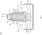
- Figures 4 and 5 show schematic top views of a bus bar 150 according to the present invention.
- the bus bar 150 comprises a first bar element 20 and a second bar element 30 separated from each other, wherein each of the first bar element 20 and the second bar element 30 are adapted to be electrically connected with one of the positive and negative electrode terminals 11 and 12 of a battery cell 10.
- each of the first bar element 20 and the second bar element 30 has a size and shape that is fitted to the size and shape of one cell terminal 11, 12.
- the first bar element 20 and the second bar element 30 comprise a conductive material, for instance, the first bar element 20 and the second bar element 30 may comprise a metal, such as aluminum or copper.
- the bus bar 150 comprises a first contact section 21 (or first fixed contact) electrically coupled to the first bar element 20 and extending in a direction toward the second bar element 30 and a second contact section 31 (or second fixed contact) electrically coupled to the second bar element 30 and extending in a direction toward the first bar element 20, wherein the first contact section 21 and the second contact section 31 are spaced away from each other.
- first bar element 20 and the second bar element 30 of the bus bar 150 are electrically disconnected from each other in an "open state" configuration and the electrical connection between the first bar element 20 and the second bar element 30 is realized by means of a relay 40.
- the relay 40 is located between the first bar element 20 and the second bar element 30 and is configured to connect the first bar element 20 and the second bar element 30 when the relay 40 is in an ON state (or closed state) and to disconnect the first bar element 20 from the second bar element 30 when the relay 40 is in an OFF state (or open state).
- the relay works as a switch between the first bar element 20 and the second bar element 30 of the bus bar 150.
- the relay 40 comprises a coil 44, a spring 45 attached to the coil 44, movable contacts 41, 42 connected to the spring 45 and having a shape corresponding to the shape of the first and second contact sections 21 and 31, respectively, and a pair of coil controlling pins 47, 48 for driving the relay.
- the relay 40 further comprises a relay case 60 accommodating the coil 44, the spring 45, and the movable contacts 41, 42.
- a connector part 70 may be provided to accommodate the coil controlling pins 47, 48.
- the connector part 70 may be provided between the relay case 60 and the battery management system 200 to protect the thin coil controlling pins 47, 48 and prevent breakage of the pins.
- the structure of the relay 40 in an ON state according to the present invention is shown in detail.
- the coil controlling pins 47, 48 supply a certain current to the coil 44, which extends, thus moving the movable contacts 41, 42 toward the contact sections 21, 31 and closing the connection between the first bar element 20 and the second bar element 30 of the bus bar 150.
- the bus bar 150 works as a conventional bus bar between the two corresponding cell terminals connected to the bus bar 150.
- the relay 40 In an OFF state of the relay 40, the current supply to the coil 44 via the coil controlling pins 47, 48 is stopped, the movable contacts 41, 42 move back to the initial position, i.e. away from the contact sections 21, 31, and the connection between the first bar element 20 and the second bar element 30 of the bus bar 150 is interrupted.
- the relay 40 may be switched OFF to protect the power interface of the battery system 500, when abnormal operating conditions occur, e.g. when a current overload is detected by a control unit of the battery system 500.
- a battery module 100 comprising at least one bus bar 150 is shown, which is connected to a battery management system (BMS) monitoring the battery cells 10 and controlling the operations of the battery system 500, and which is adapted to supply power to an external load 300.
- BMS battery management system
- a relay switch 40 is provided along the bus bar 150 for connecting the bus bar during normal operation conditions of the battery and for disconnecting the bus bar when abnormal operation conditions occur.
- a fuse 2 is further provided between the relay 40 and the battery module 100 to enhance the functionality of the protection system.
- the coil controlling pins 47, 48 of the relay 40 are connected to a relay control device 210 for driving the relay 40, i.e. for switching the relay 40 ON/OFF.
- the relay control device 210 is adapted to exchange information with the main control unit (MCU) 230 of the battery management system 200, which monitors the state of the battery cells 10.
- MCU main control unit
- the relay-based switch During normal operation of the battery system the relay-based switch is turned on, so that the relay 40 always consumes current. Because of the prolonged use of the relay 40 during normal operation, the mechanical parts of a relay are failure-prone and provide only a limited lifetime. In case the relay 40 breaks down, the power supply of the battery system 500 will be interrupted. It is therefore necessary to monitor the proper functioning of the relay 40.
- the monitoring pins 23, 33 electrically connect the first bar element 20 and the second bar element 30, respectively, of the bus bar 150 with a relay monitoring device 220 included in the battery management system 200.
- the relay monitoring device 220 measures the voltages at the first and second monitoring pins 23 and 33, which correspond to the voltages at the first and second bar elements 20, 30.
- the relay 40 When the relay 40 is ON, the first bar element 20 is electrically connected to the second bar element 30. Thus, the voltages measured by the monitoring pins 23, 33 must also be the same, if the relay 40 is working properly.
- the relay monitoring device 220 measures different voltages at the first and second monitoring pins 23 and 33 while the relay is ON - i.e. while the coil controlling pins 47, 48 supply a current to the relay 40 - it means that the relay 40 is damaged. In this case a damaged relay signal is generated by the relay monitoring device 220 and sent to the main control unit 240.
- the monitoring pins 23, 33 are usually formed as two small bus bars respectively attached to the first bar element 20 and the second bar element 30 of the bus bar 150.
- PCB printed circuit board
- the monitoring pins 23, 33 are accommodated inside the relay case 60 and the connector part 70. However, because they are accommodated nearby the coil controlling pins 47, 48, a short-circuit between the coil controlling pins 47, 48 and the monitoring pins 23, 33, may occur. In fact, while the coil controlling pins 47, 48 for driving the relay 40 usually have a relatively low voltage (e.g. 12 V or less), the monitoring pins 23, 33, which are attached to the bus bar 150, may have higher voltages up to 60V or more.
- a short-circuit between monitoring pins 23, 33 and coil controlling pins 47, 48 may therefore damage the printed circuit board comprising the control electronics.
- resistors 24, 34 are installed along the monitoring pins 23, 33, so to limit the current going through the monitoring pins 23, 33.
- Fig. 6 shows a detailed top view of the first bar element 20 and the first monitoring pin 23 attached to the first bar element 20.
- the second monitoring pin 33 is attached to the second bar element 30 of the bus bar 150.
- a resistor 24 is assembled along the first monitoring pin 23.
- the resistor 24 may be soldered to the monitoring pin 23, although different methods may be used for assembling the resistor 23.
- the resistor may have a resistance greater than 10 K ⁇ . Furthermore, the tolerance of the resistance value may not exceed 1% in order not to limit the sensing of the monitoring pins 23, 33 so that an accurate voltage measurement can be achieved.
- the resistors used are automotive specified and approved (AECQ qualified). In particular, wirewound resistors are used, which in case of failure transit to an open state, thus interrupting the connection.
- the resistors may be standard resistors or customized resistors depending on the requirements.
- resistors assembled along the monitoring pins are used for limiting the current flowing through the monitoring pins, thereby preventing damage to the control electronics in case of short-circuit between the monitoring pins and the coil controlling pins for driving the relay.
- This solution is cost-effective and requires no additional wire harnesses.
Landscapes
- Chemical & Material Sciences (AREA)
- Chemical Kinetics & Catalysis (AREA)
- Electrochemistry (AREA)
- General Chemical & Material Sciences (AREA)
- Engineering & Computer Science (AREA)
- Manufacturing & Machinery (AREA)
- Secondary Cells (AREA)
- Connection Of Batteries Or Terminals (AREA)
Abstract
Description
- The present invention relates to a bus bar for a battery system, particularly to a disconnectable bus bar comprising a relay switch for connecting/disconnecting the bus bar and monitoring pins for monitoring the relay. The invention further relates to a battery system comprising at least one disconnectable bus bar with integrated relay and monitoring pins.
- A rechargeable or secondary battery differs from a primary battery in that it can be repeatedly charged and discharged, while the latter provides only an irreversible conversion of chemical to electrical energy. Low-capacity rechargeable batteries are used as power supply for small electronic devices, such as cellular phones, notebook computers and camcorders, while high-capacity rechargeable batteries are used as the power supply for hybrid vehicles and the like.
- In general, rechargeable batteries include an electrode assembly including a positive electrode, a negative electrode, and a separator interposed between the positive and negative electrodes, a case receiving the electrode assembly, and an electrode terminal electrically connected to the electrode assembly. An electrolyte solution is injected into the case in order to enable charging and discharging of the battery via an electrochemical reaction of the positive electrode, the negative electrode, and the electrolyte solution. The shape of the case, e.g. cylindrical or rectangular, depends on the battery's intended purpose.
- Rechargeable batteries may be used as a battery module formed of a plurality of unit battery cells coupled in series and/or in parallel by a bus bar so as to provide a high energy density, e.g. for motor driving of a hybrid vehicle. Such battery modules may be mechanically and electrically integrated, equipped with a thermal management system and set up for communication with each other and one or more electrical consumers in order to form a battery system.
- For meeting the dynamic power demands of various electrical consumers connected to the battery system a static control of battery power output and charging is not sufficient. Thus, steady or intermittent exchange of information between the battery system and the controllers of the electrical consumers is required. This information includes the battery systems actual state of charge (SoC), potential electrical performance, charging ability and internal resistance as well as actual or predicted power demands or surpluses of the consumers.
- For monitoring, controlling and/or setting of the aforementioned parameters, a battery system usually comprises a battery management system (BMS). Such control unit may be an integral part of the battery system and disposed within a common housing or may be part of a remote control unit communicating with the battery system via a suitable communication bus. In both cases, the control unit may communicate with the electrical consumers via a suitable communication bus, e.g. a CAN or SPI interface.
- A battery system may further comprise a protection system to provide a voltage level control of a power interface of the battery system and to enable a fast and reliable safety shutdown of the power interface in the case of non-permissible operating conditions. Such protection system may be adapted to shutdown an electrical connection between the serially connected cells and an external terminal of the battery system. A typical protection system comprises an electromechanical switch and a driving circuit, e.g. a relay with a corresponding relay circuit. The switch can be combined with a fuse that is serially connected to the switch and melts during a constant overload to backup the safety shutdown.
- Protection systems based on relay switches and fuses have some disadvantages. In particular, as the mechanical parts of a relay are failure-prone, protection systems based thereon provide only a limited lifetime.
- In order to overcome these disadvantages monitoring pins coupled between the bas bar and the printed circuit board (PCB) comprising the battery management system (BMS) may be used for controlling whether the relay is properly working. Further, the monitoring pins may be integrated inside the relay case and connector so that the monitoring pins are protected and installation space can be saved.
- However, in case a short circuit between the monitoring pins and the coil control pins of the relay occurs, the electronics of the printed circuit board may be damaged.
- It is thus an object of the present invention to overcome or reduce at least some of the drawbacks of the prior art and to provide monitoring pins for monitoring the functions of a relay switch and which can prevent damages to electronic components of the BMS.
- One or more of the drawbacks of the prior art can be avoided or at least reduced by means of the present invention. In particular, a disconnectable bus bar for a battery system is provided which includes a relay switch for interrupting the connection when abnormal conditions occur and monitoring pins for monitoring the proper working of the relay, wherein resistors are mounted along the monitoring pins to prevent damages to the control electronics in case of a short circuit.
- According to an aspect of the present invention a disconnectable bus bar is provided comprising a first bar element and a second bar element that are spaced apart from each other, preferably along a length direction of the bus bar. The bus bar is configured to connect cell terminals of battery cells and/or battery cell modules within the battery system. Preferably, the bus bar is configured to electrically connect the terminals of battery cells with each other within the battery system. The bus bar comprises a first and second contacts electrically connected to the first and second bar elements, respectively, and spaced apart from each other, a relay configured to control a connection between the first and second contacts, and first and second monitoring pins electrically coupled to the first and second bar elements, respectively, and wherein each of the first and second monitoring pins comprises a resistor located between a first end and a second end of the monitoring pin. The monitoring pins may have the form of wires or elongated bars comprising a first end and a second end.
- In other words, a resistor with well defined ohmic resistance is structurally and electrically integrated into each of the monitoring pins.
- Preferably, the relay comprises a coil, first and second movable contacts connected to the coil and adapted to be moved by the coil, and a couple of coil controlling pins for driving the relay between a closed position and an open position. In the closed position the first and second movable contacts are electrically connected to the first and second contacts, respectively, and in the open position the first and second movable contacts are electrically disconnected from the first and second contacts. The first and second movable contacts are electrically connected to each other.
- Preferably, a relay case is accommodating the relay and a connector part connected to the relay case is accommodating the coil controlling pins, for protecting the relay and the coil controlling pins from breakage. Preferably, the monitoring pins are also accommodated inside the relay case and the connector part.
- Preferably, the resistors have a resistance value greater than 10 KΩ and smaller than 20KΩ. Preferably, a tolerance of the resistance value of the resistors is smaller than or equal to 1%. Preferably, wirewound resistors are used. The resistors may be configured to fuse and go to an open state in case of short circuit.
- According to another aspect of the invention, a battery system is provided, comprising a battery module with a plurality of battery cells, wherein each battery cell has a first cell terminal of a first polarity and a second cell terminal of a second polarity different from the first polarity. The battery system comprises at least one bus bar as disclosed above for electrically interconnecting at least two of the plurality of battery cells and a battery management system for monitoring the plurality of battery cells and driving the battery module, wherein the connector part is connected to a printed circuit board comprising the battery management system and the battery management system is configured to drive the relay to switch between an open state and a closed state via the coil controlling pins and to monitor the state of the relay via the monitoring pins. In a preferred configuration, the first bar element of the bus bar may be electrically connected to one of the first and second cell terminals of a first battery cell of the plurality of battery cells and the second bar element of the bus bar may be electrically connected to one of the first and second cell terminals of a second battery cell of the plurality of battery cells.
- Preferably, the battery management system comprises a relay driver connected to the coil control pins for driving the relay between an open state and a closed state, a relay monitoring system connected to the monitoring pins for monitoring the proper functioning of the relay, and a main control unit for controlling both the relay driver and the relay monitoring system. The relay monitoring system may be adapted to measure a voltage difference between the first monitoring pin and the second monitoring pin and to generate and send a relay failure signal to the main control unit when the relay is in a closed state and the voltage of the first monitoring pin is different from the voltage of the second monitoring pin.
- Another aspect of the present invention relates to an electric vehicle, comprising a bus bar as described above and a battery system as described above. Further aspects of the present invention could be learned from the dependent claims or the following description.
- Features will become apparent to those of ordinary skill in the art by describing in detail exemplary embodiments with reference to the attached drawings in which:
-
Fig. 1 illustrates a schematic perspective view of a battery system including a conventional bus bar; -
Fig. 2 illustrates a top view of a battery system including a bus bar according to an embodiment of the present invention; -
Fig. 3 illustrates a block diagram of a battery system including a bus bar according to an embodiment of the present invention; -
Fig. 4 illustrates a detailed top view of a bus bar including a relay in an OFF state according to an embodiment of the present invention; -
Fig. 5 illustrates a detailed top view of the bus bar ofFIG. 4 including a relay in an ON state; -
Fig. 6 illustrates a detailed top view of the first terminal of the bus bar ofFig. 4 . - Reference will now be made in detail to embodiments, examples of which are illustrated in the accompanying drawings. Effects and features of the exemplary embodiments, and implementation methods thereof will be described with reference to the accompanying drawings. In the drawings, like reference numerals denote like elements, and redundant descriptions are omitted. The present invention, however, may be embodied in various different forms, and should not be construed as being limited to only the illustrated embodiments herein. Rather, these embodiments are provided as examples so that this disclosure will be thorough and complete, and will fully convey the aspects and features of the present invention to those skilled in the art.
- Accordingly, processes, elements, and techniques that are not considered necessary to those having ordinary skill in the art for a complete understanding of the aspects and features of the present invention may not be described. In the drawings, the relative sizes of elements, layers, and regions may be exaggerated for clarity. As used herein, the terms of a singular form may include plural forms unless the context clearly indicates otherwise.
- It will be understood that although the terms "first" and "second" are used to describe various elements, these elements should not be limited by these terms. These terms are only used to distinguish one element from another element. For example, a first element may be named a second element and, similarly, a second element may be named a first element, without departing from the scope of the present invention. As used herein, the term "and/or" includes any and all combinations of one or more of the associated listed items. Expressions such as "at least one of," when preceding a list of elements, modify the entire list of elements and do not modify the individual elements of the list.
-
Figure 1 illustrates a battery system including a conventional bus bar. Abattery module 100 includes a plurality ofbattery cells 10 aligned in one direction. A pair ofend plates 18 are provided to face wide surfaces of thebattery cells 10 at the outside of thebattery cells 10, and aconnection plate 19 is configured to connect the pair ofend plates 18 to each other thereby fixing the plurality ofbattery cells 10 together. - Here, each
battery cell 10 is a prismatic (or rectangular) cell, the wide flat surfaces of the cells being stacked together to form thebattery module 100, however the present invention is not limited thereto and battery cells of different forms may be used. Further, eachbattery cell 10 includes a battery case configured for accommodation of an electrode assembly and an electrolyte. The battery case is hermetically sealed by acap assembly 14. Thecap assembly 14 is provided with positive andnegative electrode terminals vent 13. Thevent 13 is a safety means of thebattery cell 10, which acts as a passage through which gas generated in thebattery cell 10 is exhausted to the outside of thebattery cell 10. The positive andnegative electrode terminals battery cells 10 are electrically connected through aconventional bus bar 50, and thebus bar 50 may be fixed by anut 16 or the like. -
Fig. 2 illustrates a top view of a battery system analogous to the battery system shown inFig. 1 , wherein the bus bars 150 include a relay that can switch between and ON state and an OFF state according to an embodiment of the present invention. - Although in the exemplary embodiment of
Fig. 2 , a plurality ofbus bars 150 between positive andnegative electrode terminals battery cells 10 is used for connecting thebattery cells 10 in series, other configurations are possible and a bus bar may be used for connecting two or more positive (or negative) electrode terminals of neighboringbattery cells 10 in parallel. -
Figure 3 shows a block diagram of abattery system 500 including abattery module 100, wherein at least onebus bar 150 of the plurality of bus bars includes arelay 40 according to an embodiment of the present invention.Figures 4 and5 show schematic top views of abus bar 150 according to the present invention. - The
bus bar 150 comprises afirst bar element 20 and asecond bar element 30 separated from each other, wherein each of thefirst bar element 20 and thesecond bar element 30 are adapted to be electrically connected with one of the positive andnegative electrode terminals battery cell 10. Particularly, each of thefirst bar element 20 and thesecond bar element 30 has a size and shape that is fitted to the size and shape of onecell terminal first bar element 20 and thesecond bar element 30 comprise a conductive material, for instance, thefirst bar element 20 and thesecond bar element 30 may comprise a metal, such as aluminum or copper. - The
bus bar 150 comprises a first contact section 21 (or first fixed contact) electrically coupled to thefirst bar element 20 and extending in a direction toward thesecond bar element 30 and a second contact section 31 (or second fixed contact) electrically coupled to thesecond bar element 30 and extending in a direction toward thefirst bar element 20, wherein thefirst contact section 21 and thesecond contact section 31 are spaced away from each other. - Accordingly, the
first bar element 20 and thesecond bar element 30 of thebus bar 150 are electrically disconnected from each other in an "open state" configuration and the electrical connection between thefirst bar element 20 and thesecond bar element 30 is realized by means of arelay 40. - The
relay 40 is located between thefirst bar element 20 and thesecond bar element 30 and is configured to connect thefirst bar element 20 and thesecond bar element 30 when therelay 40 is in an ON state (or closed state) and to disconnect thefirst bar element 20 from thesecond bar element 30 when therelay 40 is in an OFF state (or open state). Thus, the relay works as a switch between thefirst bar element 20 and thesecond bar element 30 of thebus bar 150. - Referring to
Fig. 4 , the structure of therelay 40 in an OFF state according to the present invention is shown in detail. Therelay 40 comprises acoil 44, aspring 45 attached to thecoil 44,movable contacts spring 45 and having a shape corresponding to the shape of the first andsecond contact sections relay 40 further comprises arelay case 60 accommodating thecoil 44, thespring 45, and themovable contacts connector part 70 may be provided to accommodate the coil controlling pins 47, 48. Theconnector part 70 may be provided between therelay case 60 and thebattery management system 200 to protect the thin coil controlling pins 47, 48 and prevent breakage of the pins. - Referring to
Fig. 5 , the structure of therelay 40 in an ON state according to the present invention is shown in detail. In an ON state of therelay 40, the coil controlling pins 47, 48 supply a certain current to thecoil 44, which extends, thus moving themovable contacts contact sections first bar element 20 and thesecond bar element 30 of thebus bar 150. In this configuration, thebus bar 150 works as a conventional bus bar between the two corresponding cell terminals connected to thebus bar 150. - In an OFF state of the
relay 40, the current supply to thecoil 44 via the coil controlling pins 47, 48 is stopped, themovable contacts contact sections first bar element 20 and thesecond bar element 30 of thebus bar 150 is interrupted. For instance, therelay 40 may be switched OFF to protect the power interface of thebattery system 500, when abnormal operating conditions occur, e.g. when a current overload is detected by a control unit of thebattery system 500. - Referring to the block diagram of
Fig. 3 , abattery module 100 comprising at least onebus bar 150 is shown, which is connected to a battery management system (BMS) monitoring thebattery cells 10 and controlling the operations of thebattery system 500, and which is adapted to supply power to anexternal load 300. Arelay switch 40 is provided along thebus bar 150 for connecting the bus bar during normal operation conditions of the battery and for disconnecting the bus bar when abnormal operation conditions occur. A fuse 2 is further provided between therelay 40 and thebattery module 100 to enhance the functionality of the protection system. The coil controlling pins 47, 48 of therelay 40 are connected to arelay control device 210 for driving therelay 40, i.e. for switching therelay 40 ON/OFF. Therelay control device 210 is adapted to exchange information with the main control unit (MCU) 230 of thebattery management system 200, which monitors the state of thebattery cells 10. - When a non-permissible operating condition occurs, e.g. when a current overload is detected by the main control unit 430, this sends a signal to relay
control device 210 to switch off therelay 40, thus protecting the power interface of the battery system. - During normal operation of the battery system the relay-based switch is turned on, so that the
relay 40 always consumes current. Because of the prolonged use of therelay 40 during normal operation, the mechanical parts of a relay are failure-prone and provide only a limited lifetime. In case therelay 40 breaks down, the power supply of thebattery system 500 will be interrupted. It is therefore necessary to monitor the proper functioning of therelay 40. - To this aim a pair of monitoring pins 23, 33 are provided for monitoring the state of the
relay 40. The monitoring pins 23, 33 electrically connect thefirst bar element 20 and thesecond bar element 30, respectively, of thebus bar 150 with arelay monitoring device 220 included in thebattery management system 200. - The
relay monitoring device 220 measures the voltages at the first and second monitoring pins 23 and 33, which correspond to the voltages at the first andsecond bar elements - When the
relay 40 is ON, thefirst bar element 20 is electrically connected to thesecond bar element 30. Thus, the voltages measured by the monitoring pins 23, 33 must also be the same, if therelay 40 is working properly. - On the contrary, if the
relay monitoring device 220 measures different voltages at the first and second monitoring pins 23 and 33 while the relay is ON - i.e. while the coil controlling pins 47, 48 supply a current to the relay 40 - it means that therelay 40 is damaged. In this case a damaged relay signal is generated by therelay monitoring device 220 and sent to the main control unit 240. - The monitoring pins 23, 33 are usually formed as two small bus bars respectively attached to the
first bar element 20 and thesecond bar element 30 of thebus bar 150. When monitoring pins or wires are directly welded between a bar element of thebus bar 150 and a printed circuit board (PCB) comprising thebattery management system 200, breakage of the exposed wires may occur, so that the electrical connection is interrupted and the monitoring of therelay 40 is rendered impossible. - In order to protect the monitoring pins 23, 33 without requiring additional space inside the battery system, the monitoring pins 23, 33 are accommodated inside the
relay case 60 and theconnector part 70. However, because they are accommodated nearby the coil controlling pins 47, 48, a short-circuit between the coil controlling pins 47, 48 and the monitoring pins 23, 33, may occur. In fact, while the coil controlling pins 47, 48 for driving therelay 40 usually have a relatively low voltage (e.g. 12 V or less), the monitoring pins 23, 33, which are attached to thebus bar 150, may have higher voltages up to 60V or more. - A short-circuit between monitoring pins 23, 33 and coil controlling pins 47, 48 may therefore damage the printed circuit board comprising the control electronics.
- To prevent damage to the electronics,
resistors -
Fig. 6 shows a detailed top view of thefirst bar element 20 and thefirst monitoring pin 23 attached to thefirst bar element 20. In an analogous way thesecond monitoring pin 33 is attached to thesecond bar element 30 of thebus bar 150. Aresistor 24 is assembled along thefirst monitoring pin 23. For instance, theresistor 24 may be soldered to themonitoring pin 23, although different methods may be used for assembling theresistor 23. - To effectively limit the current going through the monitoring pin, the resistor may have a resistance greater than 10 KΩ. Furthermore, the tolerance of the resistance value may not exceed 1% in order not to limit the sensing of the monitoring pins 23, 33 so that an accurate voltage measurement can be achieved.
- The resistors used are automotive specified and approved (AECQ qualified). In particular, wirewound resistors are used, which in case of failure transit to an open state, thus interrupting the connection. The resistors may be standard resistors or customized resistors depending on the requirements.
- According to the present invention, resistors assembled along the monitoring pins are used for limiting the current flowing through the monitoring pins, thereby preventing damage to the control electronics in case of short-circuit between the monitoring pins and the coil controlling pins for driving the relay. This solution is cost-effective and requires no additional wire harnesses.
Claims (12)
- A bus bar (150) for a battery module (100), comprising:a first bar element (20) and a second bar element (30) spaced apart from each other;a first contact (21) electrically connected to the first bar element (20) and a second contact (31) electrically connected to the second bar element (30) and spaced apart from the first contact (21);a relay (40) configured to control a connection between the first and second contacts (21, 31); anda first monitoring pin (23) electrically coupled to the first bar element (20) and a second monitoring pin (33) electrically coupled to the second bar element (30);wherein each of the first and second monitoring pins (23, 33) comprises a resistor (24, 34) located between a first end and a second end of the monitoring pin (23, 33).
- The bus bar (150) according to claim 1, wherein the relay (40) comprises:a coil (44);movable contacts (41, 42) connected to the coil (44) and adapted to be moved by the coil (44), wherein the movable contacts (41, 42) are electrically connected to each other;a couple of coil controlling pins (47, 48) for driving the relay (40) between the closed position and the open position;wherein in a closed position the movable contacts (41, 42) are respectively connected to the first and second contacts (21, 31) and in an open position the movable contacts (41, 42) are electrically disconnected from the first and second contacts (21, 31).
- The bus bar (150) according to claim 2, further comprising a relay case (60) accommodating the relay (40) and a connector part (70) connected to the relay case (60) and accommodating the coil controlling pins (47, 48),
wherein the monitoring pins (23, 33) are located inside the relay case (60) and the connector part (70). - The bus bar (150) according to one of the preceding claims, wherein the resistors (24, 34) have a resistance value greater than 10 KΩ and smaller than 20 KΩ
- The bus bar (150) according to claim 4, wherein the resistance value of the resistors (24, 34) has a tolerance smaller than or equal to 1%.
- The bus bar (150) according to any one of the preceding claims, wherein the resistors (24, 34) are wirewound resistors.
- The bus bar (150) according to any one of the preceding claims, wherein the resistors (24, 34) are configured to fuse and transit to an open state in case of short circuit.
- A battery system (500), comprising:a battery module (100) comprising a plurality of battery cells (10), each battery cell (10) having a first cell terminal (11) of a first polarity and a second cell terminal (12) of a second polarity;at least one bus bar (150) according to any one of the claims 1 to 7 for electrically interconnecting at least two of the plurality of battery cells (10);a battery management system (BMS) for monitoring the plurality of battery cells (10) and driving the battery module (100);wherein the first and second monitoring pins (23, 33) are connected to a printed circuit board (PCB) comprised in the battery management system (BMS) and wherein the battery management system (BMS) is configured to drive the relay (40) to monitor the state of the relay (40) via the monitoring pins (23, 33).
- The battery system of claim 8, wherein the first bar element (20) of the bus bar (150) is electrically connected to one of the first and second cell terminals (11, 12) of a first battery cell of the plurality of battery cells (10) and the second bar element (30) of the bus bar (150) is electrically connected to the other one of the first and second cell terminals (11, 12) of a second battery cell of the plurality of battery cells (10).
- The battery system of one of claims 8 and 9, wherein the battery management system (BMS) comprises:a relay driver (210) connected to the coil controlling pins (47, 48) for driving the relay (40) between an open state and a closed state;a relay monitoring system (220) connected to the monitoring pins (23, 33) for monitoring the proper functioning of the relay (40); anda main control unit (230) for controlling both the relay driver (210) and the relay monitoring system (220).
- The battery system of claim 10, wherein the relay monitoring system (220) is adapted to measure a voltage difference between the first monitoring pin (23) and the second monitoring pin (33).
- The battery system of claim 11, wherein the relay monitoring system (220) is adapted to generate a relay failure signal and to send the relay failure signal to the main control unit (230) when the relay (40) is in a closed state and the voltage of the first monitoring pin (23) is different from the voltage of the second monitoring pin (33).
Priority Applications (1)
| Application Number | Priority Date | Filing Date | Title |
|---|---|---|---|
| EP17196059.4A EP3471172B1 (en) | 2017-10-12 | 2017-10-12 | Disconnectable bus bar for a battery system and battery system including the same |
Applications Claiming Priority (1)
| Application Number | Priority Date | Filing Date | Title |
|---|---|---|---|
| EP17196059.4A EP3471172B1 (en) | 2017-10-12 | 2017-10-12 | Disconnectable bus bar for a battery system and battery system including the same |
Publications (2)
| Publication Number | Publication Date |
|---|---|
| EP3471172A1 true EP3471172A1 (en) | 2019-04-17 |
| EP3471172B1 EP3471172B1 (en) | 2020-05-06 |
Family
ID=60083176
Family Applications (1)
| Application Number | Title | Priority Date | Filing Date |
|---|---|---|---|
| EP17196059.4A Active EP3471172B1 (en) | 2017-10-12 | 2017-10-12 | Disconnectable bus bar for a battery system and battery system including the same |
Country Status (1)
| Country | Link |
|---|---|
| EP (1) | EP3471172B1 (en) |
Cited By (2)
| Publication number | Priority date | Publication date | Assignee | Title |
|---|---|---|---|---|
| CN111313930A (en) * | 2019-12-24 | 2020-06-19 | 香江科技股份有限公司 | Relay unit and its application system |
| FR3108208A1 (en) * | 2020-03-10 | 2021-09-17 | Psa Automobiles Sa | SECURE BATTERY BLOCK TO AVOID HYDROGEN PRODUCTION IN CASE OF WATER-BASED LIQUID INTRUSION |
Citations (3)
| Publication number | Priority date | Publication date | Assignee | Title |
|---|---|---|---|---|
| US20140093752A1 (en) * | 2012-09-28 | 2014-04-03 | Byd Company Limited | Power battery assembly |
| JP2016100186A (en) * | 2014-11-21 | 2016-05-30 | 住友重機械工業株式会社 | Power storage device |
| WO2017150088A1 (en) * | 2016-02-29 | 2017-09-08 | 株式会社オートネットワーク技術研究所 | Wiring module |
-
2017
- 2017-10-12 EP EP17196059.4A patent/EP3471172B1/en active Active
Patent Citations (3)
| Publication number | Priority date | Publication date | Assignee | Title |
|---|---|---|---|---|
| US20140093752A1 (en) * | 2012-09-28 | 2014-04-03 | Byd Company Limited | Power battery assembly |
| JP2016100186A (en) * | 2014-11-21 | 2016-05-30 | 住友重機械工業株式会社 | Power storage device |
| WO2017150088A1 (en) * | 2016-02-29 | 2017-09-08 | 株式会社オートネットワーク技術研究所 | Wiring module |
Cited By (2)
| Publication number | Priority date | Publication date | Assignee | Title |
|---|---|---|---|---|
| CN111313930A (en) * | 2019-12-24 | 2020-06-19 | 香江科技股份有限公司 | Relay unit and its application system |
| FR3108208A1 (en) * | 2020-03-10 | 2021-09-17 | Psa Automobiles Sa | SECURE BATTERY BLOCK TO AVOID HYDROGEN PRODUCTION IN CASE OF WATER-BASED LIQUID INTRUSION |
Also Published As
| Publication number | Publication date |
|---|---|
| EP3471172B1 (en) | 2020-05-06 |
Similar Documents
| Publication | Publication Date | Title |
|---|---|---|
| KR101404712B1 (en) | Battery Pack of Improved Safety | |
| EP2259365B1 (en) | Device for detecting abnormality in a secondary battery | |
| EP2171824B1 (en) | Method of deactivating faulty battery cells | |
| KR101130050B1 (en) | Middle or Large-sized Battery Pack of Improved Safety | |
| EP2930771B1 (en) | Rechargeable battery | |
| CN104380563B (en) | The battery management system of the robustness with the raising for negative voltage | |
| EP2876725A1 (en) | Protection apparatus for rechargeable battery | |
| US20180212223A1 (en) | Buss bar assembly for a battery system | |
| KR20190108999A (en) | Integrated switching apparatus | |
| CN114976495B (en) | Thermal protection of connectors | |
| US20240079749A1 (en) | Power source device and method for manufacturing same | |
| EP3471172B1 (en) | Disconnectable bus bar for a battery system and battery system including the same | |
| EP3703178B1 (en) | Battery module | |
| US12609423B2 (en) | Relay control system and battery system | |
| EP4060785B1 (en) | Battery system and vehicle including the battery system | |
| KR20230111655A (en) | Battery disconnect unit, battery system and operating method thereof | |
| KR102843391B1 (en) | Relay, relay system and operation method thereof | |
| KR20130123981A (en) | Battery pack system with integration mount fuse apparatus for circuit breaking over-current in sensing assembly structure | |
| WO2019193637A1 (en) | Battery device and vehicle | |
| CN114982036A (en) | Battery disconnect unit including moving plate | |
| EP4560338A1 (en) | Battery contact failure detecting device and method | |
| JP2019161702A (en) | Circuit protection device and power supply monitoring device | |
| EP4124498A1 (en) | Relay control system and battery system | |
| KR20250137231A (en) | Secondary battery and secondary battery module having the same | |
| KR20220014990A (en) | Safety unit replacing MSD using interlock circuit |
Legal Events
| Date | Code | Title | Description |
|---|---|---|---|
| PUAI | Public reference made under article 153(3) epc to a published international application that has entered the european phase |
Free format text: ORIGINAL CODE: 0009012 |
|
| STAA | Information on the status of an ep patent application or granted ep patent |
Free format text: STATUS: THE APPLICATION HAS BEEN PUBLISHED |
|
| AK | Designated contracting states |
Kind code of ref document: A1 Designated state(s): AL AT BE BG CH CY CZ DE DK EE ES FI FR GB GR HR HU IE IS IT LI LT LU LV MC MK MT NL NO PL PT RO RS SE SI SK SM TR |
|
| AX | Request for extension of the european patent |
Extension state: BA ME |
|
| STAA | Information on the status of an ep patent application or granted ep patent |
Free format text: STATUS: REQUEST FOR EXAMINATION WAS MADE |
|
| 17P | Request for examination filed |
Effective date: 20191002 |
|
| RBV | Designated contracting states (corrected) |
Designated state(s): AL AT BE BG CH CY CZ DE DK EE ES FI FR GB GR HR HU IE IS IT LI LT LU LV MC MK MT NL NO PL PT RO RS SE SI SK SM TR |
|
| GRAP | Despatch of communication of intention to grant a patent |
Free format text: ORIGINAL CODE: EPIDOSNIGR1 |
|
| STAA | Information on the status of an ep patent application or granted ep patent |
Free format text: STATUS: GRANT OF PATENT IS INTENDED |
|
| GRAS | Grant fee paid |
Free format text: ORIGINAL CODE: EPIDOSNIGR3 |
|
| GRAA | (expected) grant |
Free format text: ORIGINAL CODE: 0009210 |
|
| STAA | Information on the status of an ep patent application or granted ep patent |
Free format text: STATUS: THE PATENT HAS BEEN GRANTED |
|
| INTG | Intention to grant announced |
Effective date: 20200312 |
|
| AK | Designated contracting states |
Kind code of ref document: B1 Designated state(s): AL AT BE BG CH CY CZ DE DK EE ES FI FR GB GR HR HU IE IS IT LI LT LU LV MC MK MT NL NO PL PT RO RS SE SI SK SM TR |
|
| REG | Reference to a national code |
Ref country code: GB Ref legal event code: FG4D |
|
| REG | Reference to a national code |
Ref country code: CH Ref legal event code: EP Ref country code: AT Ref legal event code: REF Ref document number: 1268272 Country of ref document: AT Kind code of ref document: T Effective date: 20200515 |
|
| REG | Reference to a national code |
Ref country code: IE Ref legal event code: FG4D |
|
| REG | Reference to a national code |
Ref country code: DE Ref legal event code: R096 Ref document number: 602017016102 Country of ref document: DE |
|
| REG | Reference to a national code |
Ref country code: LT Ref legal event code: MG4D |
|
| REG | Reference to a national code |
Ref country code: NL Ref legal event code: MP Effective date: 20200506 |
|
| PG25 | Lapsed in a contracting state [announced via postgrant information from national office to epo] |
Ref country code: SE Free format text: LAPSE BECAUSE OF FAILURE TO SUBMIT A TRANSLATION OF THE DESCRIPTION OR TO PAY THE FEE WITHIN THE PRESCRIBED TIME-LIMIT Effective date: 20200506 Ref country code: LT Free format text: LAPSE BECAUSE OF FAILURE TO SUBMIT A TRANSLATION OF THE DESCRIPTION OR TO PAY THE FEE WITHIN THE PRESCRIBED TIME-LIMIT Effective date: 20200506 Ref country code: IS Free format text: LAPSE BECAUSE OF FAILURE TO SUBMIT A TRANSLATION OF THE DESCRIPTION OR TO PAY THE FEE WITHIN THE PRESCRIBED TIME-LIMIT Effective date: 20200906 Ref country code: NO Free format text: LAPSE BECAUSE OF FAILURE TO SUBMIT A TRANSLATION OF THE DESCRIPTION OR TO PAY THE FEE WITHIN THE PRESCRIBED TIME-LIMIT Effective date: 20200806 Ref country code: GR Free format text: LAPSE BECAUSE OF FAILURE TO SUBMIT A TRANSLATION OF THE DESCRIPTION OR TO PAY THE FEE WITHIN THE PRESCRIBED TIME-LIMIT Effective date: 20200807 Ref country code: PT Free format text: LAPSE BECAUSE OF FAILURE TO SUBMIT A TRANSLATION OF THE DESCRIPTION OR TO PAY THE FEE WITHIN THE PRESCRIBED TIME-LIMIT Effective date: 20200907 Ref country code: FI Free format text: LAPSE BECAUSE OF FAILURE TO SUBMIT A TRANSLATION OF THE DESCRIPTION OR TO PAY THE FEE WITHIN THE PRESCRIBED TIME-LIMIT Effective date: 20200506 |
|
| REG | Reference to a national code |
Ref country code: DE Ref legal event code: R079 Ref document number: 602017016102 Country of ref document: DE Free format text: PREVIOUS MAIN CLASS: H01M0002200000 Ipc: H01M0050500000 |
|
| PG25 | Lapsed in a contracting state [announced via postgrant information from national office to epo] |
Ref country code: LV Free format text: LAPSE BECAUSE OF FAILURE TO SUBMIT A TRANSLATION OF THE DESCRIPTION OR TO PAY THE FEE WITHIN THE PRESCRIBED TIME-LIMIT Effective date: 20200506 Ref country code: HR Free format text: LAPSE BECAUSE OF FAILURE TO SUBMIT A TRANSLATION OF THE DESCRIPTION OR TO PAY THE FEE WITHIN THE PRESCRIBED TIME-LIMIT Effective date: 20200506 Ref country code: BG Free format text: LAPSE BECAUSE OF FAILURE TO SUBMIT A TRANSLATION OF THE DESCRIPTION OR TO PAY THE FEE WITHIN THE PRESCRIBED TIME-LIMIT Effective date: 20200806 Ref country code: RS Free format text: LAPSE BECAUSE OF FAILURE TO SUBMIT A TRANSLATION OF THE DESCRIPTION OR TO PAY THE FEE WITHIN THE PRESCRIBED TIME-LIMIT Effective date: 20200506 |
|
| PG25 | Lapsed in a contracting state [announced via postgrant information from national office to epo] |
Ref country code: NL Free format text: LAPSE BECAUSE OF FAILURE TO SUBMIT A TRANSLATION OF THE DESCRIPTION OR TO PAY THE FEE WITHIN THE PRESCRIBED TIME-LIMIT Effective date: 20200506 Ref country code: AL Free format text: LAPSE BECAUSE OF FAILURE TO SUBMIT A TRANSLATION OF THE DESCRIPTION OR TO PAY THE FEE WITHIN THE PRESCRIBED TIME-LIMIT Effective date: 20200506 |
|
| PG25 | Lapsed in a contracting state [announced via postgrant information from national office to epo] |
Ref country code: RO Free format text: LAPSE BECAUSE OF FAILURE TO SUBMIT A TRANSLATION OF THE DESCRIPTION OR TO PAY THE FEE WITHIN THE PRESCRIBED TIME-LIMIT Effective date: 20200506 Ref country code: CZ Free format text: LAPSE BECAUSE OF FAILURE TO SUBMIT A TRANSLATION OF THE DESCRIPTION OR TO PAY THE FEE WITHIN THE PRESCRIBED TIME-LIMIT Effective date: 20200506 Ref country code: ES Free format text: LAPSE BECAUSE OF FAILURE TO SUBMIT A TRANSLATION OF THE DESCRIPTION OR TO PAY THE FEE WITHIN THE PRESCRIBED TIME-LIMIT Effective date: 20200506 Ref country code: SM Free format text: LAPSE BECAUSE OF FAILURE TO SUBMIT A TRANSLATION OF THE DESCRIPTION OR TO PAY THE FEE WITHIN THE PRESCRIBED TIME-LIMIT Effective date: 20200506 Ref country code: EE Free format text: LAPSE BECAUSE OF FAILURE TO SUBMIT A TRANSLATION OF THE DESCRIPTION OR TO PAY THE FEE WITHIN THE PRESCRIBED TIME-LIMIT Effective date: 20200506 Ref country code: DK Free format text: LAPSE BECAUSE OF FAILURE TO SUBMIT A TRANSLATION OF THE DESCRIPTION OR TO PAY THE FEE WITHIN THE PRESCRIBED TIME-LIMIT Effective date: 20200506 Ref country code: IT Free format text: LAPSE BECAUSE OF FAILURE TO SUBMIT A TRANSLATION OF THE DESCRIPTION OR TO PAY THE FEE WITHIN THE PRESCRIBED TIME-LIMIT Effective date: 20200506 |
|
| REG | Reference to a national code |
Ref country code: DE Ref legal event code: R097 Ref document number: 602017016102 Country of ref document: DE |
|
| PG25 | Lapsed in a contracting state [announced via postgrant information from national office to epo] |
Ref country code: SK Free format text: LAPSE BECAUSE OF FAILURE TO SUBMIT A TRANSLATION OF THE DESCRIPTION OR TO PAY THE FEE WITHIN THE PRESCRIBED TIME-LIMIT Effective date: 20200506 Ref country code: PL Free format text: LAPSE BECAUSE OF FAILURE TO SUBMIT A TRANSLATION OF THE DESCRIPTION OR TO PAY THE FEE WITHIN THE PRESCRIBED TIME-LIMIT Effective date: 20200506 |
|
| PLBE | No opposition filed within time limit |
Free format text: ORIGINAL CODE: 0009261 |
|
| STAA | Information on the status of an ep patent application or granted ep patent |
Free format text: STATUS: NO OPPOSITION FILED WITHIN TIME LIMIT |
|
| 26N | No opposition filed |
Effective date: 20210209 |
|
| PG25 | Lapsed in a contracting state [announced via postgrant information from national office to epo] |
Ref country code: SI Free format text: LAPSE BECAUSE OF FAILURE TO SUBMIT A TRANSLATION OF THE DESCRIPTION OR TO PAY THE FEE WITHIN THE PRESCRIBED TIME-LIMIT Effective date: 20200506 |
|
| REG | Reference to a national code |
Ref country code: CH Ref legal event code: PL |
|
| PG25 | Lapsed in a contracting state [announced via postgrant information from national office to epo] |
Ref country code: LU Free format text: LAPSE BECAUSE OF NON-PAYMENT OF DUE FEES Effective date: 20201012 Ref country code: MC Free format text: LAPSE BECAUSE OF FAILURE TO SUBMIT A TRANSLATION OF THE DESCRIPTION OR TO PAY THE FEE WITHIN THE PRESCRIBED TIME-LIMIT Effective date: 20200506 |
|
| REG | Reference to a national code |
Ref country code: BE Ref legal event code: MM Effective date: 20201031 |
|
| PG25 | Lapsed in a contracting state [announced via postgrant information from national office to epo] |
Ref country code: BE Free format text: LAPSE BECAUSE OF NON-PAYMENT OF DUE FEES Effective date: 20201031 Ref country code: CH Free format text: LAPSE BECAUSE OF NON-PAYMENT OF DUE FEES Effective date: 20201031 Ref country code: LI Free format text: LAPSE BECAUSE OF NON-PAYMENT OF DUE FEES Effective date: 20201031 |
|
| PG25 | Lapsed in a contracting state [announced via postgrant information from national office to epo] |
Ref country code: IE Free format text: LAPSE BECAUSE OF NON-PAYMENT OF DUE FEES Effective date: 20201012 |
|
| PG25 | Lapsed in a contracting state [announced via postgrant information from national office to epo] |
Ref country code: TR Free format text: LAPSE BECAUSE OF FAILURE TO SUBMIT A TRANSLATION OF THE DESCRIPTION OR TO PAY THE FEE WITHIN THE PRESCRIBED TIME-LIMIT Effective date: 20200506 Ref country code: MT Free format text: LAPSE BECAUSE OF FAILURE TO SUBMIT A TRANSLATION OF THE DESCRIPTION OR TO PAY THE FEE WITHIN THE PRESCRIBED TIME-LIMIT Effective date: 20200506 Ref country code: CY Free format text: LAPSE BECAUSE OF FAILURE TO SUBMIT A TRANSLATION OF THE DESCRIPTION OR TO PAY THE FEE WITHIN THE PRESCRIBED TIME-LIMIT Effective date: 20200506 |
|
| PG25 | Lapsed in a contracting state [announced via postgrant information from national office to epo] |
Ref country code: MK Free format text: LAPSE BECAUSE OF FAILURE TO SUBMIT A TRANSLATION OF THE DESCRIPTION OR TO PAY THE FEE WITHIN THE PRESCRIBED TIME-LIMIT Effective date: 20200506 |
|
| REG | Reference to a national code |
Ref country code: AT Ref legal event code: UEP Ref document number: 1268272 Country of ref document: AT Kind code of ref document: T Effective date: 20200506 |
|
| P01 | Opt-out of the competence of the unified patent court (upc) registered |
Effective date: 20230528 |
|
| PGFP | Annual fee paid to national office [announced via postgrant information from national office to epo] |
Ref country code: FR Payment date: 20250930 Year of fee payment: 9 |
|
| PGFP | Annual fee paid to national office [announced via postgrant information from national office to epo] |
Ref country code: DE Payment date: 20250930 Year of fee payment: 9 |
|
| PGFP | Annual fee paid to national office [announced via postgrant information from national office to epo] |
Ref country code: GB Payment date: 20251001 Year of fee payment: 9 |
|
| PGFP | Annual fee paid to national office [announced via postgrant information from national office to epo] |
Ref country code: AT Payment date: 20251009 Year of fee payment: 9 |