EP3471119A1 - Electrode assembly, energy storage device comprising the electrode assembly and a method for producing the electrode assembly - Google Patents
Electrode assembly, energy storage device comprising the electrode assembly and a method for producing the electrode assembly Download PDFInfo
- Publication number
- EP3471119A1 EP3471119A1 EP17195822.6A EP17195822A EP3471119A1 EP 3471119 A1 EP3471119 A1 EP 3471119A1 EP 17195822 A EP17195822 A EP 17195822A EP 3471119 A1 EP3471119 A1 EP 3471119A1
- Authority
- EP
- European Patent Office
- Prior art keywords
- separator
- electrode assembly
- electrode material
- folds
- terminal
- Prior art date
- Legal status (The legal status is an assumption and is not a legal conclusion. Google has not performed a legal analysis and makes no representation as to the accuracy of the status listed.)
- Granted
Links
Images


Classifications
-
- H—ELECTRICITY
- H01—ELECTRIC ELEMENTS
- H01G—CAPACITORS; CAPACITORS, RECTIFIERS, DETECTORS, SWITCHING DEVICES, LIGHT-SENSITIVE OR TEMPERATURE-SENSITIVE DEVICES OF THE ELECTROLYTIC TYPE
- H01G11/00—Hybrid capacitors, i.e. capacitors having different positive and negative electrodes; Electric double-layer [EDL] capacitors; Processes for the manufacture thereof or of parts thereof
- H01G11/22—Electrodes
- H01G11/26—Electrodes characterised by their structure, e.g. multi-layered, porosity or surface features
-
- H—ELECTRICITY
- H01—ELECTRIC ELEMENTS
- H01G—CAPACITORS; CAPACITORS, RECTIFIERS, DETECTORS, SWITCHING DEVICES, LIGHT-SENSITIVE OR TEMPERATURE-SENSITIVE DEVICES OF THE ELECTROLYTIC TYPE
- H01G11/00—Hybrid capacitors, i.e. capacitors having different positive and negative electrodes; Electric double-layer [EDL] capacitors; Processes for the manufacture thereof or of parts thereof
- H01G11/10—Multiple hybrid or EDL capacitors, e.g. arrays or modules
- H01G11/12—Stacked hybrid or EDL capacitors
-
- H—ELECTRICITY
- H01—ELECTRIC ELEMENTS
- H01G—CAPACITORS; CAPACITORS, RECTIFIERS, DETECTORS, SWITCHING DEVICES, LIGHT-SENSITIVE OR TEMPERATURE-SENSITIVE DEVICES OF THE ELECTROLYTIC TYPE
- H01G11/00—Hybrid capacitors, i.e. capacitors having different positive and negative electrodes; Electric double-layer [EDL] capacitors; Processes for the manufacture thereof or of parts thereof
- H01G11/74—Terminals, e.g. extensions of current collectors
-
- H—ELECTRICITY
- H01—ELECTRIC ELEMENTS
- H01G—CAPACITORS; CAPACITORS, RECTIFIERS, DETECTORS, SWITCHING DEVICES, LIGHT-SENSITIVE OR TEMPERATURE-SENSITIVE DEVICES OF THE ELECTROLYTIC TYPE
- H01G11/00—Hybrid capacitors, i.e. capacitors having different positive and negative electrodes; Electric double-layer [EDL] capacitors; Processes for the manufacture thereof or of parts thereof
- H01G11/78—Cases; Housings; Encapsulations; Mountings
- H01G11/82—Fixing or assembling a capacitive element in a housing, e.g. mounting electrodes, current collectors or terminals in containers or encapsulations
-
- H—ELECTRICITY
- H01—ELECTRIC ELEMENTS
- H01G—CAPACITORS; CAPACITORS, RECTIFIERS, DETECTORS, SWITCHING DEVICES, LIGHT-SENSITIVE OR TEMPERATURE-SENSITIVE DEVICES OF THE ELECTROLYTIC TYPE
- H01G11/00—Hybrid capacitors, i.e. capacitors having different positive and negative electrodes; Electric double-layer [EDL] capacitors; Processes for the manufacture thereof or of parts thereof
- H01G11/84—Processes for the manufacture of hybrid or EDL capacitors, or components thereof
-
- H—ELECTRICITY
- H01—ELECTRIC ELEMENTS
- H01G—CAPACITORS; CAPACITORS, RECTIFIERS, DETECTORS, SWITCHING DEVICES, LIGHT-SENSITIVE OR TEMPERATURE-SENSITIVE DEVICES OF THE ELECTROLYTIC TYPE
- H01G11/00—Hybrid capacitors, i.e. capacitors having different positive and negative electrodes; Electric double-layer [EDL] capacitors; Processes for the manufacture thereof or of parts thereof
- H01G11/52—Separators
-
- Y—GENERAL TAGGING OF NEW TECHNOLOGICAL DEVELOPMENTS; GENERAL TAGGING OF CROSS-SECTIONAL TECHNOLOGIES SPANNING OVER SEVERAL SECTIONS OF THE IPC; TECHNICAL SUBJECTS COVERED BY FORMER USPC CROSS-REFERENCE ART COLLECTIONS [XRACs] AND DIGESTS
- Y02—TECHNOLOGIES OR APPLICATIONS FOR MITIGATION OR ADAPTATION AGAINST CLIMATE CHANGE
- Y02E—REDUCTION OF GREENHOUSE GAS [GHG] EMISSIONS, RELATED TO ENERGY GENERATION, TRANSMISSION OR DISTRIBUTION
- Y02E60/00—Enabling technologies; Technologies with a potential or indirect contribution to GHG emissions mitigation
- Y02E60/10—Energy storage using batteries
-
- Y—GENERAL TAGGING OF NEW TECHNOLOGICAL DEVELOPMENTS; GENERAL TAGGING OF CROSS-SECTIONAL TECHNOLOGIES SPANNING OVER SEVERAL SECTIONS OF THE IPC; TECHNICAL SUBJECTS COVERED BY FORMER USPC CROSS-REFERENCE ART COLLECTIONS [XRACs] AND DIGESTS
- Y02—TECHNOLOGIES OR APPLICATIONS FOR MITIGATION OR ADAPTATION AGAINST CLIMATE CHANGE
- Y02E—REDUCTION OF GREENHOUSE GAS [GHG] EMISSIONS, RELATED TO ENERGY GENERATION, TRANSMISSION OR DISTRIBUTION
- Y02E60/00—Enabling technologies; Technologies with a potential or indirect contribution to GHG emissions mitigation
- Y02E60/13—Energy storage using capacitors
-
- Y—GENERAL TAGGING OF NEW TECHNOLOGICAL DEVELOPMENTS; GENERAL TAGGING OF CROSS-SECTIONAL TECHNOLOGIES SPANNING OVER SEVERAL SECTIONS OF THE IPC; TECHNICAL SUBJECTS COVERED BY FORMER USPC CROSS-REFERENCE ART COLLECTIONS [XRACs] AND DIGESTS
- Y02—TECHNOLOGIES OR APPLICATIONS FOR MITIGATION OR ADAPTATION AGAINST CLIMATE CHANGE
- Y02P—CLIMATE CHANGE MITIGATION TECHNOLOGIES IN THE PRODUCTION OR PROCESSING OF GOODS
- Y02P70/00—Climate change mitigation technologies in the production process for final industrial or consumer products
- Y02P70/50—Manufacturing or production processes characterised by the final manufactured product
Definitions
- an electrode assembly comprising a fan-folded multilayer containing a separator as an inner layer, current collectors as outer layers, and electrode material between the two sides of the separator and the current collectors, and a first terminal that is attached to the upward folds of the fan-folded multilayer and a second terminal that is attached to the downward folds of the fan-folded multilayer.
- the first terminal covers the upward folds and the second terminal covers the downward folds of the fan-folded multilayer.
- the electrode assembly of the present invention thus allows the current to directly flow from the electrodes across the thickness of the current collector and the thickness of the terminal to its outer surface.
- the two sides of the separator are directly coated with the electrode material.
- the current collectors are usually coated with electrode material prior to being assembled. This leads to the disadvantage that electrode assemblies according to the state of art do not provide a uniform distance between the two opposing electrodes separated by a separator and/or that the two opposing electrodes have a large distance to each other. In the assembly according to the present invention, wherein the electrode material is directly coated on the separator, the disadvantages are overcome.
- the present invention is further directed to an energy storage device comprising an electrode assembly according to the present invention.
- An energy storage device according to the present invention is any device that can capture energy produced at one time for use at later time, such as batteries, secondary batteries and capacitors.
- the energy storage device is a capacitor, preferably an electric double-layer capacitor.
- An electric double-layer capacitor is a high-capacity capacitor that mainly achieve separation of charge in a Helmholtz double layer at the interface between the surface of the electrodes and the electrolyte liquid.
- the step of applying electrode material on the first and on the second side of the separator is periodically interrupted to form segments of electrode material, which are uniformly spaced apart from one another, wherein the segments of electrode material of the first side of the separator are located directly opposite of the segments of electrode material of the second side of the separator.
- the segments of electrode material of the one side of the separator exactly overlap the segments of electrode material of the other side of the separator before being folded.
- the gaps between the segments of electrode material of the two sides of the separator exactly overlap before being folded in the plan view.
- the multilayer is folded at each gap so that the fan-folded multilayer consists of five layers between the folds and three layers at the folds.
- the method further comprises the step of determining the position of the segments of electrode material and/or of the gaps between the segments before joining the coated separator with the current collectors, and, optionally, adjusting the folding device to ensure that the multilayer electrode assembly is folded at the gaps.
- the current collectors cover the two sides of the separator, it is hardly possible to determine the positions of the segments of electrode material and gaps. According to the present invention, these positions are therefore determined before the current collectors are joined with the separator.
- the positions of the gaps are transmitted to a control device, which is able to adjust the folding device to ensure that the multilayer is folded at the gaps.
Landscapes
- Engineering & Computer Science (AREA)
- Power Engineering (AREA)
- Microelectronics & Electronic Packaging (AREA)
- Manufacturing & Machinery (AREA)
- Secondary Cells (AREA)
- Electric Double-Layer Capacitors Or The Like (AREA)
- Battery Electrode And Active Subsutance (AREA)
Abstract
Description
- The present invention relates to an electrode assembly, an energy storage device comprising the electrode assembly and a method for producing the electrode assembly.
- Electrode assemblies are components of energy storage devices such as batteries, secondary batteries and capacitors. In the state of art, there are usually two types of electrode assemblies that are used in said energy storage devices. There are spiral-wound electrode assemblies, wherein two continuous electrodes laid on top of the other are wound into a cylindrical configuration. On the other hand, there are stacked, multi-plate electrode assemblies, wherein the individual electrode plates are stacked parallel to each other. Recently, stacked electrode assemblies have been developed, wherein continuous lengths of material are used to form parallel stacked electrode assemblies. The advantage of using continuous lengths of material is that the number of individual components and the number of mechanical connections required between the electrodes is reduced and thus, the assembly process is simplified.
- A disadvantage of these stacked electrode assemblies using continuous lengths of material according to the state of art is that there is a large distance from the electrodes or at least from some of the electrodes or at least from some points of the electrodes to the terminal or to the point of the terminal that is connected to the conducting surfaces of the energy storage device comprising the electrode assembly. Thus, the electrode assemblies have a large internal resistance. The production process of these electrode assemblies according to the state of art is furthermore quite complex. It is often necessary to remove already applied electrode material during the further process or to incorporate non-conductive portions in the current collectors, for example.
- It is an object of the present invention therefore to provide an electrode assembly having a short distance from any point of the electrodes to the outer surface of the respective terminal and having a defined and short distance between the two opposing electrodes.
- It has been found that the above-mentioned disadvantages can be dealt with when an electrode assembly is provided comprising a fan-folded multilayer containing a separator as an inner layer, current collectors as outer layers, and electrode material between the two sides of the separator and the current collectors, and a first terminal that is attached to the upward folds of the fan-folded multilayer and a second terminal that is attached to the downward folds of the fan-folded multilayer.
- The fan-folded multilayer comprises a separator as an inner layer, whose two sides are at least partially covered with electrode material, and current collectors as outer layers, which cover both sides of the at least partially covered separator. The multilayer thus provides a five-layer structure of current collector/electrode material/separator/electrode material/current collector. At portions, where the separator is not covered with electrode material, the multilayer comprises a three-layer structure of current collector/separator/current collector only.
- The fan-folded multilayer is a multilayer having a fan-fold (i.e. according fold or zigzag) configuration. The fan-folded multilayer comprises a plurality of segments, which are each separated by a fold. In a compressed state, these segments are stacked parallel to each other. It is preferred that the multilayer is precisely folded that the segments between the folds all have the same length so that all upward folds are on one level and all downward folds are on one level.
- The separator separates two opposite electrodes to prevent a short circuit. Furthermore, the separator provides the basis for the electrode material that is coated thereon. The separator is preferably as thin as possible, needs to be ion-permeable and should be chemically inert to the further components. Paper material, polymer material, woven glass fibers, woven ceramic fibers as well as nonwoven materials can be used as a separator, for example. Preferably, a continuous length of these materials is used as a separator. The separator according to the present invention preferably have a thickness in the range of 5-50 µm, more preferably 10-40 µm, in particular 15-30 µm.
- Preferably, the separator is soaked with an electrolytic liquid, which is a conductive solvent containing positive and negative ions. The electrolytic liquid provides the electrically conductive connection between the two opposite electrodes that are separated by the separator. Preferably, the electrolyte liquid is chemically inert to the further components, provides a low viscosity and a high self-decomposition voltage.
- The electrode material between the separator and the current collectors form the electrodes. The electrode material may be of any material or a mixture of materials, which is conductive and has large surface area. Preferably, the electrode material comprises porous carbon, graphene, carbon nanotubes, oxides of transition metals including ruthenium, iridium, iron and manganese, lithium-metal oxides, sulfides including titanium sulfide, or a mixture thereof, more preferably the electrode material comprises porous carbon, graphene, carbon nanotubes or a mixture thereof. The electrode material can furthermore comprise a binding agent. The binding agent is preferably present in an amount of less than 20 % per weight, preferably less than 10 % per weight, more preferably less than 5 % per weight of the electrode material. The binding agent is preferably a thermoplastic polymer. In one embodiment, all electrodes have the same composition. In a further embodiment the electrodes have a different composition. The electrodes according to the present invention preferably have a thickness in the range of 1-100 µm, preferably 5-50 µm, more preferably 10-40 µm, in particular 15-30 µm.
- Current collectors forming the outer layers of the fan-folded multilayer cover the two sides of the separator containing the electrode material. A current collector is a conductive layer, preferably a metallic conductive layer, more preferably an aluminum layer. Preferably, a continuous length of these layers is used as a current collector. The two current collectors connect the electrodes to the terminals and thus provide electrical conduction between electrodes and terminals.
- The first terminal covers the upward folds and the second terminal covers the downward folds of the fan-folded multilayer. The electrode assembly of the present invention thus allows the current to directly flow from the electrodes across the thickness of the current collector and the thickness of the terminal to its outer surface.
- Preferably, the first terminal and/or second terminal is attached to the folds over the entire length of the folds. The connections of the terminals to the folds over the entire length of the folds provide larger contact areas. Thus, the current flow is improved by minimizing the distance from any point of the electrode to the outer surfaces of the terminals. The terminals can be of any conductive material that is known to a person skilled in the art for that purpose.
- In a preferred embodiment, the first terminal and/or second terminal have a form of a plate, preferably a rectangular plate. In the plan view and in the bottom view, the fan-folded multilayer in a compressed state forms a rectangular area showing the upward folds and the downward folds so that rectangular plates can completely cover all folds.
- Preferably, the two sides of the separator are directly coated with the electrode material. According to the state of art, the current collectors are usually coated with electrode material prior to being assembled. This leads to the disadvantage that electrode assemblies according to the state of art do not provide a uniform distance between the two opposing electrodes separated by a separator and/or that the two opposing electrodes have a large distance to each other. In the assembly according to the present invention, wherein the electrode material is directly coated on the separator, the disadvantages are overcome.
- Any method known to a person skilled in the art for coating a separator material with electrode material can be used for coating of the separator. In a preferred embodiment, the electrode material is printed on the separator using a carbon ink, for example. In a more preferred embodiment, the separator is coated by a method for dry coating a separator with electrode material comprising the steps of charging a separator electrostatically, and applying electrode material on the electrostatically charged separator. Preferably, the step of electrostatically charging the separator is carried out by contacting the separator with a charged object, preferably with a charged roller. The charged object comprises at least one charged area and at least one uncharged area. The pattern of charged and uncharged areas is transferred to the separator so that the electrode material is applied to the charged areas of the separator only. The electrode material is preferably applied by a material transfer roller. The separator can be folded at the areas, which are not coated with electrode material, without the necessity of removing already applied electrode material form the separator.
- Preferably, the separator is not coated with the electrode material at the folds. This ensures that possible damages of the thin separator resulting from the folding do not lead to a short circuit. However, it is preferred if the separator is entirely coated with the electrode material between two adjacent folds to provide a large electrode surface area.
- The fan-folded multilayer preferably further comprises conductive material, preferably conductive material comprising aluminum, between the electrode material and the current collectors. The outer surface of the electrode material, which is in contact with the current collector, is uneven at the microscopic level, in particular if the electrode material comprises carbon nanotubes. To obtain an even surface even at the microscopic level, conductive material can additionally be applied on the electrode material. The conductive material preferably comprises an aluminum powder, more preferably an aluminum powder having different particles sizes. The conductive material can furthermore comprise a binding agent. The binding agent is preferably present in an amount of less than 20 % per weight, preferably less than 10 % per weight, more preferably less than 5 % per weight of the electrode material. The binding agent is preferably a thermoplastic polymer.
- The present invention is further directed to an energy storage device comprising an electrode assembly according to the present invention. An energy storage device according to the present invention is any device that can capture energy produced at one time for use at later time, such as batteries, secondary batteries and capacitors.
- The energy storage device may further comprise a housing, which can be any housing known to a person skilled in the art for that purpose. Such housings comprise conducting and non-conducting surfaces. In a preferred embodiment, the energy storage device further comprises a housing having conducting and non-conductive surfaces, wherein the outer surfaces of the first and second terminal of the electrode assembly are the conducting surfaces of the housing. Preferably, these conducting surfaces are parts of the outer surface of the housing so that two or more energy storage devices can be stacked, whereby a conducting surface of a first energy storage device is in contact with a conducting surface of a second energy storage device.
- According to a preferred embodiment, the energy storage device is a capacitor, preferably an electric double-layer capacitor. An electric double-layer capacitor is a high-capacity capacitor that mainly achieve separation of charge in a Helmholtz double layer at the interface between the surface of the electrodes and the electrolyte liquid.
- The present invention is further directed to a method for producing a fan-folded electrode assembly according to the present invention comprising the steps of applying electrode material on the first and on the second side of the separator, applying an electrolytic liquid on the coated separator, joining current collectors with the obtained separator so that the current collectors form the outer layers, folding the obtained multilayer electrode assembly into a fan-fold configuration, and attaching a first terminal to the upward folds and a second terminal to the downward folds. The electrode material is preferably applied by dry coating the electrode material on the two sides of the separator. Preferably, the method of the present invention is carried out in order indicated.
- In a preferred embodiment, the step of applying electrode material on the first and on the second side of the separator is periodically interrupted to form segments of electrode material, which are uniformly spaced apart from one another, wherein the segments of electrode material of the first side of the separator are located directly opposite of the segments of electrode material of the second side of the separator. In the plan view, the segments of electrode material of the one side of the separator exactly overlap the segments of electrode material of the other side of the separator before being folded. Similarly, the gaps between the segments of electrode material of the two sides of the separator exactly overlap before being folded in the plan view. Preferably, the multilayer is folded at each gap so that the fan-folded multilayer consists of five layers between the folds and three layers at the folds.
- In a preferred embodiment, the method further comprises the step of determining the position of the segments of electrode material and/or of the gaps between the segments before joining the coated separator with the current collectors, and, optionally, adjusting the folding device to ensure that the multilayer electrode assembly is folded at the gaps. After the current collectors cover the two sides of the separator, it is hardly possible to determine the positions of the segments of electrode material and gaps. According to the present invention, these positions are therefore determined before the current collectors are joined with the separator. The positions of the gaps are transmitted to a control device, which is able to adjust the folding device to ensure that the multilayer is folded at the gaps.
- Preferably, the method of the present invention comprises the step of compressing the folded multilayer electrode assembly that the segments, which are separated by the folds, are stacked parallel to each other. Hereby, the capacity in relation to the base area of the electrode assembly is enhanced.
- Preferably, the method further comprises the step of cutting the obtained fan-folded multilayer electrode assembly. The step of cutting optionally includes the step of counting the folds and cutting the fan-folded multilayer after a predetermined number of folds.
- Preferred embodiments of the present invention will be described with reference to the drawings as follows.
-
Fig. 1 illustrates a cross-sectional view of a fan-folded multilayer of an electrode assembly according to the present invention. -
Fig. 2 illustrates a cross-sectional view of an electrode assembly according to the present invention. -
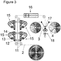
Fig. 3 illustrates a production process for the fan-folded multilayer of an electrode assembly according to the present invention. -
Fig. 1 illustrates a fan-folded multilayer comprising aseparator 2 as an inner layer andcurrent collectors separator 2 are at least partially coated withelectrode material separator 2 is coated withelectrode material folds separator 2 is not coated at thefolds upward folds 7 and downward folds 8. -
Fig. 2 illustrates anelectrode assembly 1 according to the present invention comprising the fan-folded multilayer shown inFigure 1 . The electrode assembly further comprises afirst terminal 9 and asecond terminal 10, which are attached to theupward folds 7 and to the downward folds 8, respectively. In an energy device according to the present invention, the outer surface of thefirst terminal 9 and the outer surface of thesecond terminal 10 are the conducting surfaces of the housing. -
Fig. 3 illustrates a production process of a fan-folded multilayer as a component of an electrode assembly according to the present invention. The two sides of theseparator 2 are coated one after the other first with segments ofelectrode material 5,6 (not indicated) and then with further conductive material. The coating is carried out bydry coating devices 15 comprising transport means 11, a chargingroller 12, amaterial transfer roller 13 and aheating roller 14. Thecoated separator 2 is conveyed through agap determination device 16, wherein the gaps between two segments ofelectrode material liquid nozzles 17, the twocurrent collectors separator 2, whichcurrent collectors folding device 18 to obtain the fan-folded multilayer, wherein the segments between thefolds 7, 8 (not indicated) are arranged parallel to each other. Attachment of the first andsecond terminal 9, 10 (not shown) to the upward and downward folds 7, 8 (not indicated) provide theelectrode assembly 1 according to the present invention.
Claims (15)
- Electrode assembly comprising
a fan-folded multilayer containinga separator as an inner layer,current collectors as outer layers, andelectrode material between the two sides of the separator and the current collectors, anda first terminal that is attached to the upward folds of the fan-folded multilayer and a second terminal that is attached to the downward folds of the fan-folded multilayer. - Electrode assembly according to Claim 1, wherein the first terminal and/or second terminal is attached to the folds over the entire length of the folds.
- Electrode assembly according to Claim 1 or 2, wherein the first terminal and/or second terminal have a form of a plate, preferably a rectangular plate.
- Electrode assembly according to any of Claims 1-3, wherein the two sides of the separator are directly coated with the electrode material.
- Electrode assembly according to any of Claims 1-4, wherein the separator is not coated with the electrode material at the folds.
- Electrode assembly according to any of Claims 1-5, wherein the separator is entirely coated with the electrode material between two adjacent folds.
- Electrode assembly according to any of Claims 1-6, wherein the fan-folded multilayer further comprises conductive material, preferably conductive material comprising aluminum, between the electrode material and the current collectors.
- Energy storage device comprising an electrode assembly according to any of Claims 1 to 7.
- Energy storage device according to Claim 8, further comprising a housing having conducting and non-conductive surfaces, wherein the outer surfaces of the first and second terminal of the electrode assembly are the conducting surfaces.
- Energy storage device according to Claim 8 or 9, wherein the energy storage device is a capacitor, preferably an electric double-layer capacitor.
- Method for producing a fan-folded electrode assembly according to any of Claims 1 to 7 comprising the steps of
applying electrode material on the first and on the second side of a separator,
applying an electrolytic liquid on the coated separator,
joining current collectors with the obtained separator so that the current collectors form the outer layers,
folding the obtained multilayer electrode assembly into a fan-fold configuration, and
attaching a first terminal to the upward folds and a second terminal to the downward folds. - Method according to Claim 11, wherein the step of applying electrode material on the first and on the second side of the separator is periodically interrupted to form segments of electrode material, which are uniformly spaced apart from one another, wherein the segments of electrode material of the first side of the separator are located directly opposite of the segments of electrode material of the second side of the separator.
- Method according to Claim 11 or 12 further comprising the step of determining the position of the segments of electrode material and/or of the gaps between the segments before joining the coated separator with the current collectors, and, optionally, adjusting the folding device to ensure that the multilayer electrode assembly is folded at the gaps.
- Method according to any of Claims 11 to 13, further comprising the step of compressing the folded multilayer electrode assembly that the segments, which are separated by the folds, are stacked parallel to each other.
- Method according to any of Claims 11 to 14, further comprising the step of cutting the obtained folded multilayer electrode assembly.
Priority Applications (10)
| Application Number | Priority Date | Filing Date | Title |
|---|---|---|---|
| PL17195822.6T PL3471119T3 (en) | 2017-10-10 | 2017-10-10 | Electrode assembly, energy storage device comprising the electrode assembly and a method for producing the electrode assembly |
| ES17195822T ES2929781T3 (en) | 2017-10-10 | 2017-10-10 | Electrode assembly, energy storage device comprising the electrode assembly and a method of producing the electrode assembly |
| LTEP17195822.6T LT3471119T (en) | 2017-10-10 | 2017-10-10 | ELECTRODE ASSEMBLY, ENERGY STORAGE COMPRISING ELECTRODE ASSEMBLY AND METHOD OF MANUFACTURING ELECTRODE ASSEMBLY |
| DK17195822.6T DK3471119T3 (en) | 2017-10-10 | 2017-10-10 | Electrode device, energy storage device comprising the electrode device, and a method of manufacturing the electrode device |
| EP17195822.6A EP3471119B1 (en) | 2017-10-10 | 2017-10-10 | Electrode assembly, energy storage device comprising the electrode assembly and a method for producing the electrode assembly |
| PCT/EP2018/077370 WO2019072781A1 (en) | 2017-10-10 | 2018-10-08 | Electrode assembly, energy storage device comprising the electrode assembly and a method for producing the electrode assembly |
| JP2020516836A JP2020537333A (en) | 2017-10-10 | 2018-10-08 | An electrode assembly, a power storage device including the electrode assembly, and a method for manufacturing the electrode assembly. |
| US16/753,820 US11302489B2 (en) | 2017-10-10 | 2018-10-08 | Electrode assembly, energy storage device comprising the electrode assembly and a method for producing the electrode assembly |
| CN201880066226.8A CN111542903B (en) | 2017-10-10 | 2018-10-08 | Electrode assembly, energy storage device including the same, and method of manufacturing the same |
| EP18795303.9A EP3695427B1 (en) | 2017-10-10 | 2018-10-08 | Electrode assembly, energy storage device comprising the electrode assembly and a method for producing the electrode assembly |
Applications Claiming Priority (1)
| Application Number | Priority Date | Filing Date | Title |
|---|---|---|---|
| EP17195822.6A EP3471119B1 (en) | 2017-10-10 | 2017-10-10 | Electrode assembly, energy storage device comprising the electrode assembly and a method for producing the electrode assembly |
Publications (2)
| Publication Number | Publication Date |
|---|---|
| EP3471119A1 true EP3471119A1 (en) | 2019-04-17 |
| EP3471119B1 EP3471119B1 (en) | 2022-09-21 |
Family
ID=60191103
Family Applications (2)
| Application Number | Title | Priority Date | Filing Date |
|---|---|---|---|
| EP17195822.6A Active EP3471119B1 (en) | 2017-10-10 | 2017-10-10 | Electrode assembly, energy storage device comprising the electrode assembly and a method for producing the electrode assembly |
| EP18795303.9A Active EP3695427B1 (en) | 2017-10-10 | 2018-10-08 | Electrode assembly, energy storage device comprising the electrode assembly and a method for producing the electrode assembly |
Family Applications After (1)
| Application Number | Title | Priority Date | Filing Date |
|---|---|---|---|
| EP18795303.9A Active EP3695427B1 (en) | 2017-10-10 | 2018-10-08 | Electrode assembly, energy storage device comprising the electrode assembly and a method for producing the electrode assembly |
Country Status (9)
| Country | Link |
|---|---|
| US (1) | US11302489B2 (en) |
| EP (2) | EP3471119B1 (en) |
| JP (1) | JP2020537333A (en) |
| CN (1) | CN111542903B (en) |
| DK (1) | DK3471119T3 (en) |
| ES (1) | ES2929781T3 (en) |
| LT (1) | LT3471119T (en) |
| PL (1) | PL3471119T3 (en) |
| WO (1) | WO2019072781A1 (en) |
Cited By (2)
| Publication number | Priority date | Publication date | Assignee | Title |
|---|---|---|---|---|
| DE102021111374A1 (en) | 2021-05-03 | 2022-11-03 | Bayerische Motoren Werke Aktiengesellschaft | Method for manufacturing a battery cell and battery cell |
| DE102021111379A1 (en) | 2021-05-03 | 2022-11-03 | Bayerische Motoren Werke Aktiengesellschaft | Electrode stack for a battery cell, battery cell and method of manufacture |
Citations (10)
| Publication number | Priority date | Publication date | Assignee | Title |
|---|---|---|---|---|
| FR1151510A (en) * | 1955-04-05 | 1958-01-31 | Plessey Co Ltd | Electrolytic capacitor and its manufacturing process |
| DE2613390A1 (en) * | 1976-03-29 | 1978-02-16 | Roederstein Kondensatoren | Prodn. of capacitors with metallised dielectric strip - uses strip folded longitudinally as it is unwound, for compression to form individual capacitors |
| EP0659299A1 (en) * | 1992-09-11 | 1995-06-28 | Valence Technology Inc | Electrochemical cell stack and method of making an electrochemical cell stack. |
| JP2000353643A (en) * | 1999-06-10 | 2000-12-19 | Honda Motor Co Ltd | Electric double layer capacitor |
| JP2001338848A (en) * | 2000-05-26 | 2001-12-07 | Matsuo Electric Co Ltd | Electric double layer capacitor |
| US20020160263A1 (en) * | 2001-02-28 | 2002-10-31 | Corrigan Dennis A. | Electrochemical cell with zigzag electrodes |
| JP3423852B2 (en) * | 1996-08-30 | 2003-07-07 | 本田技研工業株式会社 | Capacitor device |
| JP2004153259A (en) * | 2002-10-09 | 2004-05-27 | Asahi Glass Co Ltd | Electric double layer capacitor and method of manufacturing the electric double layer capacitor |
| US20050019652A1 (en) * | 2003-07-21 | 2005-01-27 | Fauteux Denis G. | Electrode assembly and method of manufacturing same |
| JP5098859B2 (en) * | 2008-07-08 | 2012-12-12 | パナソニック株式会社 | Electric double layer capacitor |
Family Cites Families (15)
| Publication number | Priority date | Publication date | Assignee | Title |
|---|---|---|---|---|
| DE3067151D1 (en) | 1979-09-12 | 1984-04-26 | Lucas Ind Plc | Battery systems employing bipolar electrodes |
| JPH0394412A (en) * | 1989-09-07 | 1991-04-19 | Isuzu Motors Ltd | Electric double layer capacitor |
| US5478668A (en) * | 1993-11-30 | 1995-12-26 | Bell Communications Research Inc. | Rechargeable lithium battery construction |
| JPH10302828A (en) * | 1997-04-28 | 1998-11-13 | Mitsubishi Cable Ind Ltd | Angular battery and manufacture thereof |
| KR100443250B1 (en) * | 1998-09-24 | 2004-08-04 | 토마스 앤드 베츠 인터내셔널, 인코포레이티드 | Improved process for manufacturing electrochemical cells |
| JP2004503912A (en) | 2000-06-14 | 2004-02-05 | エリオン アクチエンゲゼルシャフト | Batteries, especially flat batteries |
| JP2004259856A (en) * | 2003-02-25 | 2004-09-16 | Honda Motor Co Ltd | Series connection structure of storage elements |
| US7102877B2 (en) * | 2003-09-12 | 2006-09-05 | Maxwell Technologies, Inc. | Electrode impregnation and bonding |
| JP4513125B2 (en) * | 2004-07-22 | 2010-07-28 | Tdk株式会社 | Electrochemical device and manufacturing method thereof |
| WO2006118053A1 (en) * | 2005-04-26 | 2006-11-09 | Matsushita Electric Industrial Co., Ltd. | Cell |
| US20080241656A1 (en) * | 2007-03-31 | 2008-10-02 | John Miller | Corrugated electrode core terminal interface apparatus and article of manufacture |
| JP2009289937A (en) * | 2008-05-29 | 2009-12-10 | Panasonic Corp | Electric double-layer capacitor |
| US20120288747A1 (en) * | 2010-01-29 | 2012-11-15 | Jsr Corporation | Electrochemical device |
| CN103165899A (en) * | 2012-12-07 | 2013-06-19 | 深圳市海太阳实业有限公司 | Positive pole piece and preparation method thereof and battery |
| CN104638213B (en) | 2015-01-30 | 2017-09-05 | 湖南高远电池有限公司 | A kind of ultra-thin secondary cell and preparation method thereof |
-
2017
- 2017-10-10 ES ES17195822T patent/ES2929781T3/en active Active
- 2017-10-10 DK DK17195822.6T patent/DK3471119T3/en active
- 2017-10-10 LT LTEP17195822.6T patent/LT3471119T/en unknown
- 2017-10-10 EP EP17195822.6A patent/EP3471119B1/en active Active
- 2017-10-10 PL PL17195822.6T patent/PL3471119T3/en unknown
-
2018
- 2018-10-08 JP JP2020516836A patent/JP2020537333A/en active Pending
- 2018-10-08 CN CN201880066226.8A patent/CN111542903B/en active Active
- 2018-10-08 EP EP18795303.9A patent/EP3695427B1/en active Active
- 2018-10-08 US US16/753,820 patent/US11302489B2/en active Active
- 2018-10-08 WO PCT/EP2018/077370 patent/WO2019072781A1/en not_active Ceased
Patent Citations (10)
| Publication number | Priority date | Publication date | Assignee | Title |
|---|---|---|---|---|
| FR1151510A (en) * | 1955-04-05 | 1958-01-31 | Plessey Co Ltd | Electrolytic capacitor and its manufacturing process |
| DE2613390A1 (en) * | 1976-03-29 | 1978-02-16 | Roederstein Kondensatoren | Prodn. of capacitors with metallised dielectric strip - uses strip folded longitudinally as it is unwound, for compression to form individual capacitors |
| EP0659299A1 (en) * | 1992-09-11 | 1995-06-28 | Valence Technology Inc | Electrochemical cell stack and method of making an electrochemical cell stack. |
| JP3423852B2 (en) * | 1996-08-30 | 2003-07-07 | 本田技研工業株式会社 | Capacitor device |
| JP2000353643A (en) * | 1999-06-10 | 2000-12-19 | Honda Motor Co Ltd | Electric double layer capacitor |
| JP2001338848A (en) * | 2000-05-26 | 2001-12-07 | Matsuo Electric Co Ltd | Electric double layer capacitor |
| US20020160263A1 (en) * | 2001-02-28 | 2002-10-31 | Corrigan Dennis A. | Electrochemical cell with zigzag electrodes |
| JP2004153259A (en) * | 2002-10-09 | 2004-05-27 | Asahi Glass Co Ltd | Electric double layer capacitor and method of manufacturing the electric double layer capacitor |
| US20050019652A1 (en) * | 2003-07-21 | 2005-01-27 | Fauteux Denis G. | Electrode assembly and method of manufacturing same |
| JP5098859B2 (en) * | 2008-07-08 | 2012-12-12 | パナソニック株式会社 | Electric double layer capacitor |
Cited By (2)
| Publication number | Priority date | Publication date | Assignee | Title |
|---|---|---|---|---|
| DE102021111374A1 (en) | 2021-05-03 | 2022-11-03 | Bayerische Motoren Werke Aktiengesellschaft | Method for manufacturing a battery cell and battery cell |
| DE102021111379A1 (en) | 2021-05-03 | 2022-11-03 | Bayerische Motoren Werke Aktiengesellschaft | Electrode stack for a battery cell, battery cell and method of manufacture |
Also Published As
| Publication number | Publication date |
|---|---|
| CN111542903A (en) | 2020-08-14 |
| US20200251291A1 (en) | 2020-08-06 |
| EP3695427B1 (en) | 2024-12-04 |
| CN111542903B (en) | 2022-11-22 |
| EP3695427C0 (en) | 2024-12-04 |
| DK3471119T3 (en) | 2022-10-03 |
| US11302489B2 (en) | 2022-04-12 |
| EP3695427A1 (en) | 2020-08-19 |
| LT3471119T (en) | 2022-11-25 |
| EP3471119B1 (en) | 2022-09-21 |
| PL3471119T3 (en) | 2022-11-21 |
| ES2929781T3 (en) | 2022-12-01 |
| JP2020537333A (en) | 2020-12-17 |
| WO2019072781A1 (en) | 2019-04-18 |
Similar Documents
| Publication | Publication Date | Title |
|---|---|---|
| KR102645603B1 (en) | high-voltage device | |
| US10644324B2 (en) | Electrode material and energy storage apparatus | |
| CN103348426B (en) | Double electric layer capacitor | |
| JP7175287B2 (en) | Electric double layer capacitor having electrodes with separator | |
| US11302489B2 (en) | Electrode assembly, energy storage device comprising the electrode assembly and a method for producing the electrode assembly | |
| US20090180238A1 (en) | Energy storage devices | |
| US7623339B2 (en) | Electrochemical device | |
| KR101944905B1 (en) | electric double layer capacitor with separating objects included electrodes | |
| KR101059891B1 (en) | High power electrical energy storage device having a unit cell and the unit cell | |
| US8369065B2 (en) | Electric double layer capacitor | |
| KR101859432B1 (en) | Portable subsidiary power supply device for rapid charging using super capacitor | |
| JPH04240708A (en) | Electric dipole layer capacitor | |
| KR101956267B1 (en) | Energy storage apparatus using electric double layer capacitor with separating objects included electrodes | |
| EP3471121A1 (en) | Method for dry coating a separator with electrode material, electrostatic dry coating device, and a separator being dry coated | |
| WO2018000023A1 (en) | Printed interdigitated super capacitor and method of manufacture | |
| JPH03116707A (en) | Electric double-layer capacitor | |
| JP2005191070A (en) | Method and apparatus for manufacturing electrode for electrochemical capacitor | |
| JP2009141098A (en) | Electric double layer capacitor | |
| JP2006049452A (en) | Electric double layer capacitor | |
| KR20170051825A (en) | Super capacitor of surface mount type and manufacture method thereof | |
| JPH03245517A (en) | Laminated type electric double-layer capacitor | |
| JP2014127611A (en) | Electrochemical device |
Legal Events
| Date | Code | Title | Description |
|---|---|---|---|
| PUAI | Public reference made under article 153(3) epc to a published international application that has entered the european phase |
Free format text: ORIGINAL CODE: 0009012 |
|
| STAA | Information on the status of an ep patent application or granted ep patent |
Free format text: STATUS: THE APPLICATION HAS BEEN PUBLISHED |
|
| AK | Designated contracting states |
Kind code of ref document: A1 Designated state(s): AL AT BE BG CH CY CZ DE DK EE ES FI FR GB GR HR HU IE IS IT LI LT LU LV MC MK MT NL NO PL PT RO RS SE SI SK SM TR |
|
| AX | Request for extension of the european patent |
Extension state: BA ME |
|
| STAA | Information on the status of an ep patent application or granted ep patent |
Free format text: STATUS: REQUEST FOR EXAMINATION WAS MADE |
|
| 17P | Request for examination filed |
Effective date: 20191015 |
|
| RBV | Designated contracting states (corrected) |
Designated state(s): AL AT BE BG CH CY CZ DE DK EE ES FI FR GB GR HR HU IE IS IT LI LT LU LV MC MK MT NL NO PL PT RO RS SE SI SK SM TR |
|
| STAA | Information on the status of an ep patent application or granted ep patent |
Free format text: STATUS: EXAMINATION IS IN PROGRESS |
|
| 17Q | First examination report despatched |
Effective date: 20211018 |
|
| GRAP | Despatch of communication of intention to grant a patent |
Free format text: ORIGINAL CODE: EPIDOSNIGR1 |
|
| STAA | Information on the status of an ep patent application or granted ep patent |
Free format text: STATUS: GRANT OF PATENT IS INTENDED |
|
| INTG | Intention to grant announced |
Effective date: 20220324 |
|
| GRAS | Grant fee paid |
Free format text: ORIGINAL CODE: EPIDOSNIGR3 |
|
| GRAA | (expected) grant |
Free format text: ORIGINAL CODE: 0009210 |
|
| STAA | Information on the status of an ep patent application or granted ep patent |
Free format text: STATUS: THE PATENT HAS BEEN GRANTED |
|
| RAP3 | Party data changed (applicant data changed or rights of an application transferred) |
Owner name: MACROCAPS APS |
|
| AK | Designated contracting states |
Kind code of ref document: B1 Designated state(s): AL AT BE BG CH CY CZ DE DK EE ES FI FR GB GR HR HU IE IS IT LI LT LU LV MC MK MT NL NO PL PT RO RS SE SI SK SM TR |
|
| REG | Reference to a national code |
Ref country code: GB Ref legal event code: FG4D |
|
| REG | Reference to a national code |
Ref country code: DE Ref legal event code: R082 Ref document number: 602017061927 Country of ref document: DE Representative=s name: DEMSKI & NOBBE PATENTANWAELTE, DE Ref country code: DE Ref legal event code: R082 Ref document number: 602017061927 Country of ref document: DE Representative=s name: SEYER & NOBBE PATENTANWAELTE PARTNERSCHAFTSGES, DE |
|
| REG | Reference to a national code |
Ref country code: CH Ref legal event code: EP |
|
| REG | Reference to a national code |
Ref country code: DK Ref legal event code: T3 Effective date: 20220927 |
|
| REG | Reference to a national code |
Ref country code: DE Ref legal event code: R096 Ref document number: 602017061927 Country of ref document: DE |
|
| REG | Reference to a national code |
Ref country code: SE Ref legal event code: TRGR |
|
| REG | Reference to a national code |
Ref country code: NL Ref legal event code: FP Ref country code: IE Ref legal event code: FG4D |
|
| REG | Reference to a national code |
Ref country code: FI Ref legal event code: FGE |
|
| REG | Reference to a national code |
Ref country code: AT Ref legal event code: REF Ref document number: 1520375 Country of ref document: AT Kind code of ref document: T Effective date: 20221015 |
|
| REG | Reference to a national code |
Ref country code: EE Ref legal event code: FG4A Ref document number: E022724 Country of ref document: EE Effective date: 20220929 |
|
| REG | Reference to a national code |
Ref country code: NO Ref legal event code: T2 Effective date: 20220921 |
|
| REG | Reference to a national code |
Ref country code: ES Ref legal event code: FG2A Ref document number: 2929781 Country of ref document: ES Kind code of ref document: T3 Effective date: 20221201 |
|
| PG25 | Lapsed in a contracting state [announced via postgrant information from national office to epo] |
Ref country code: RS Free format text: LAPSE BECAUSE OF FAILURE TO SUBMIT A TRANSLATION OF THE DESCRIPTION OR TO PAY THE FEE WITHIN THE PRESCRIBED TIME-LIMIT Effective date: 20220921 |
|
| PG25 | Lapsed in a contracting state [announced via postgrant information from national office to epo] |
Ref country code: HR Free format text: LAPSE BECAUSE OF FAILURE TO SUBMIT A TRANSLATION OF THE DESCRIPTION OR TO PAY THE FEE WITHIN THE PRESCRIBED TIME-LIMIT Effective date: 20220921 Ref country code: GR Free format text: LAPSE BECAUSE OF FAILURE TO SUBMIT A TRANSLATION OF THE DESCRIPTION OR TO PAY THE FEE WITHIN THE PRESCRIBED TIME-LIMIT Effective date: 20221222 |
|
| PG25 | Lapsed in a contracting state [announced via postgrant information from national office to epo] |
Ref country code: SM Free format text: LAPSE BECAUSE OF FAILURE TO SUBMIT A TRANSLATION OF THE DESCRIPTION OR TO PAY THE FEE WITHIN THE PRESCRIBED TIME-LIMIT Effective date: 20220921 Ref country code: RO Free format text: LAPSE BECAUSE OF FAILURE TO SUBMIT A TRANSLATION OF THE DESCRIPTION OR TO PAY THE FEE WITHIN THE PRESCRIBED TIME-LIMIT Effective date: 20220921 Ref country code: PT Free format text: LAPSE BECAUSE OF FAILURE TO SUBMIT A TRANSLATION OF THE DESCRIPTION OR TO PAY THE FEE WITHIN THE PRESCRIBED TIME-LIMIT Effective date: 20230123 Ref country code: CZ Free format text: LAPSE BECAUSE OF FAILURE TO SUBMIT A TRANSLATION OF THE DESCRIPTION OR TO PAY THE FEE WITHIN THE PRESCRIBED TIME-LIMIT Effective date: 20220921 |
|
| PG25 | Lapsed in a contracting state [announced via postgrant information from national office to epo] |
Ref country code: SK Free format text: LAPSE BECAUSE OF FAILURE TO SUBMIT A TRANSLATION OF THE DESCRIPTION OR TO PAY THE FEE WITHIN THE PRESCRIBED TIME-LIMIT Effective date: 20220921 Ref country code: IS Free format text: LAPSE BECAUSE OF FAILURE TO SUBMIT A TRANSLATION OF THE DESCRIPTION OR TO PAY THE FEE WITHIN THE PRESCRIBED TIME-LIMIT Effective date: 20230121 |
|
| REG | Reference to a national code |
Ref country code: DE Ref legal event code: R097 Ref document number: 602017061927 Country of ref document: DE |
|
| P01 | Opt-out of the competence of the unified patent court (upc) registered |
Effective date: 20230523 |
|
| PG25 | Lapsed in a contracting state [announced via postgrant information from national office to epo] |
Ref country code: MC Free format text: LAPSE BECAUSE OF FAILURE TO SUBMIT A TRANSLATION OF THE DESCRIPTION OR TO PAY THE FEE WITHIN THE PRESCRIBED TIME-LIMIT Effective date: 20220921 Ref country code: LU Free format text: LAPSE BECAUSE OF NON-PAYMENT OF DUE FEES Effective date: 20221010 Ref country code: AL Free format text: LAPSE BECAUSE OF FAILURE TO SUBMIT A TRANSLATION OF THE DESCRIPTION OR TO PAY THE FEE WITHIN THE PRESCRIBED TIME-LIMIT Effective date: 20220921 |
|
| PLBE | No opposition filed within time limit |
Free format text: ORIGINAL CODE: 0009261 |
|
| STAA | Information on the status of an ep patent application or granted ep patent |
Free format text: STATUS: NO OPPOSITION FILED WITHIN TIME LIMIT |
|
| 26N | No opposition filed |
Effective date: 20230622 |
|
| PG25 | Lapsed in a contracting state [announced via postgrant information from national office to epo] |
Ref country code: SI Free format text: LAPSE BECAUSE OF FAILURE TO SUBMIT A TRANSLATION OF THE DESCRIPTION OR TO PAY THE FEE WITHIN THE PRESCRIBED TIME-LIMIT Effective date: 20220921 |
|
| REG | Reference to a national code |
Ref country code: DE Ref legal event code: R082 Ref document number: 602017061927 Country of ref document: DE Representative=s name: SEYER & NOBBE PATENTANWAELTE PARTNERSCHAFTSGES, DE |
|
| PG25 | Lapsed in a contracting state [announced via postgrant information from national office to epo] |
Ref country code: HU Free format text: LAPSE BECAUSE OF FAILURE TO SUBMIT A TRANSLATION OF THE DESCRIPTION OR TO PAY THE FEE WITHIN THE PRESCRIBED TIME-LIMIT; INVALID AB INITIO Effective date: 20171010 |
|
| PG25 | Lapsed in a contracting state [announced via postgrant information from national office to epo] |
Ref country code: CY Free format text: LAPSE BECAUSE OF FAILURE TO SUBMIT A TRANSLATION OF THE DESCRIPTION OR TO PAY THE FEE WITHIN THE PRESCRIBED TIME-LIMIT Effective date: 20220921 |
|
| PG25 | Lapsed in a contracting state [announced via postgrant information from national office to epo] |
Ref country code: MK Free format text: LAPSE BECAUSE OF FAILURE TO SUBMIT A TRANSLATION OF THE DESCRIPTION OR TO PAY THE FEE WITHIN THE PRESCRIBED TIME-LIMIT Effective date: 20220921 |
|
| PG25 | Lapsed in a contracting state [announced via postgrant information from national office to epo] |
Ref country code: TR Free format text: LAPSE BECAUSE OF FAILURE TO SUBMIT A TRANSLATION OF THE DESCRIPTION OR TO PAY THE FEE WITHIN THE PRESCRIBED TIME-LIMIT Effective date: 20220921 |
|
| PG25 | Lapsed in a contracting state [announced via postgrant information from national office to epo] |
Ref country code: BG Free format text: LAPSE BECAUSE OF FAILURE TO SUBMIT A TRANSLATION OF THE DESCRIPTION OR TO PAY THE FEE WITHIN THE PRESCRIBED TIME-LIMIT Effective date: 20220921 |
|
| PG25 | Lapsed in a contracting state [announced via postgrant information from national office to epo] |
Ref country code: MT Free format text: LAPSE BECAUSE OF FAILURE TO SUBMIT A TRANSLATION OF THE DESCRIPTION OR TO PAY THE FEE WITHIN THE PRESCRIBED TIME-LIMIT Effective date: 20220921 |
|
| PGFP | Annual fee paid to national office [announced via postgrant information from national office to epo] |
Ref country code: LT Payment date: 20250925 Year of fee payment: 9 |
|
| REG | Reference to a national code |
Ref country code: CH Ref legal event code: U11 Free format text: ST27 STATUS EVENT CODE: U-0-0-U10-U11 (AS PROVIDED BY THE NATIONAL OFFICE) Effective date: 20251101 |
|
| PGFP | Annual fee paid to national office [announced via postgrant information from national office to epo] |
Ref country code: NL Payment date: 20251023 Year of fee payment: 9 |
|
| PGFP | Annual fee paid to national office [announced via postgrant information from national office to epo] |
Ref country code: DE Payment date: 20251020 Year of fee payment: 9 |
|
| PGFP | Annual fee paid to national office [announced via postgrant information from national office to epo] |
Ref country code: GB Payment date: 20251024 Year of fee payment: 9 |
|
| PGFP | Annual fee paid to national office [announced via postgrant information from national office to epo] |
Ref country code: NO Payment date: 20251022 Year of fee payment: 9 |
|
| PGFP | Annual fee paid to national office [announced via postgrant information from national office to epo] |
Ref country code: AT Payment date: 20251021 Year of fee payment: 9 |
|
| PGFP | Annual fee paid to national office [announced via postgrant information from national office to epo] |
Ref country code: FI Payment date: 20251022 Year of fee payment: 9 Ref country code: DK Payment date: 20251023 Year of fee payment: 9 Ref country code: IT Payment date: 20251031 Year of fee payment: 9 |
|
| PGFP | Annual fee paid to national office [announced via postgrant information from national office to epo] |
Ref country code: FR Payment date: 20251027 Year of fee payment: 9 |
|
| PGFP | Annual fee paid to national office [announced via postgrant information from national office to epo] |
Ref country code: BE Payment date: 20251022 Year of fee payment: 9 |
|
| PGFP | Annual fee paid to national office [announced via postgrant information from national office to epo] |
Ref country code: SE Payment date: 20251023 Year of fee payment: 9 Ref country code: CH Payment date: 20251101 Year of fee payment: 9 |
|
| PGFP | Annual fee paid to national office [announced via postgrant information from national office to epo] |
Ref country code: IE Payment date: 20251021 Year of fee payment: 9 |
|
| PGFP | Annual fee paid to national office [announced via postgrant information from national office to epo] |
Ref country code: LV Payment date: 20251021 Year of fee payment: 9 |
|
| PGFP | Annual fee paid to national office [announced via postgrant information from national office to epo] |
Ref country code: PL Payment date: 20251001 Year of fee payment: 9 |
|
| PGFP | Annual fee paid to national office [announced via postgrant information from national office to epo] |
Ref country code: EE Payment date: 20251020 Year of fee payment: 9 |
|
| PGFP | Annual fee paid to national office [announced via postgrant information from national office to epo] |
Ref country code: ES Payment date: 20251114 Year of fee payment: 9 |