EP3471075B1 - Method for collision avoidance between a vulnerable road user vehicle and a surrounding vehicle, vulnerable road user vehicle, further vehicle and computer program - Google Patents
Method for collision avoidance between a vulnerable road user vehicle and a surrounding vehicle, vulnerable road user vehicle, further vehicle and computer program Download PDFInfo
- Publication number
- EP3471075B1 EP3471075B1 EP17196570.0A EP17196570A EP3471075B1 EP 3471075 B1 EP3471075 B1 EP 3471075B1 EP 17196570 A EP17196570 A EP 17196570A EP 3471075 B1 EP3471075 B1 EP 3471075B1
- Authority
- EP
- European Patent Office
- Prior art keywords
- vehicle
- road user
- vulnerable road
- user vehicle
- data
- Prior art date
- Legal status (The legal status is an assumption and is not a legal conclusion. Google has not performed a legal analysis and makes no representation as to the accuracy of the status listed.)
- Active
Links
Images


Classifications
-
- B—PERFORMING OPERATIONS; TRANSPORTING
- B60—VEHICLES IN GENERAL
- B60W—CONJOINT CONTROL OF VEHICLE SUB-UNITS OF DIFFERENT TYPE OR DIFFERENT FUNCTION; CONTROL SYSTEMS SPECIALLY ADAPTED FOR HYBRID VEHICLES; ROAD VEHICLE DRIVE CONTROL SYSTEMS FOR PURPOSES NOT RELATED TO THE CONTROL OF A PARTICULAR SUB-UNIT
- B60W30/00—Purposes of road vehicle drive control systems not related to the control of a particular sub-unit, e.g. of systems using conjoint control of vehicle sub-units
- B60W30/08—Active safety systems predicting or avoiding probable or impending collision or attempting to minimise its consequences
- B60W30/095—Predicting travel path or likelihood of collision
- B60W30/0953—Predicting travel path or likelihood of collision the prediction being responsive to vehicle dynamic parameters
-
- B—PERFORMING OPERATIONS; TRANSPORTING
- B60—VEHICLES IN GENERAL
- B60W—CONJOINT CONTROL OF VEHICLE SUB-UNITS OF DIFFERENT TYPE OR DIFFERENT FUNCTION; CONTROL SYSTEMS SPECIALLY ADAPTED FOR HYBRID VEHICLES; ROAD VEHICLE DRIVE CONTROL SYSTEMS FOR PURPOSES NOT RELATED TO THE CONTROL OF A PARTICULAR SUB-UNIT
- B60W30/00—Purposes of road vehicle drive control systems not related to the control of a particular sub-unit, e.g. of systems using conjoint control of vehicle sub-units
- B60W30/08—Active safety systems predicting or avoiding probable or impending collision or attempting to minimise its consequences
- B60W30/09—Taking automatic action to avoid collision, e.g. braking and steering
-
- B—PERFORMING OPERATIONS; TRANSPORTING
- B60—VEHICLES IN GENERAL
- B60W—CONJOINT CONTROL OF VEHICLE SUB-UNITS OF DIFFERENT TYPE OR DIFFERENT FUNCTION; CONTROL SYSTEMS SPECIALLY ADAPTED FOR HYBRID VEHICLES; ROAD VEHICLE DRIVE CONTROL SYSTEMS FOR PURPOSES NOT RELATED TO THE CONTROL OF A PARTICULAR SUB-UNIT
- B60W50/00—Details of control systems for road vehicle drive control not related to the control of a particular sub-unit, e.g. process diagnostic or vehicle driver interfaces
- B60W50/08—Interaction between the driver and the control system
- B60W50/14—Means for informing the driver, warning the driver or prompting a driver intervention
-
- G—PHYSICS
- G01—MEASURING; TESTING
- G01C—MEASURING DISTANCES, LEVELS OR BEARINGS; SURVEYING; NAVIGATION; GYROSCOPIC INSTRUMENTS; PHOTOGRAMMETRY OR VIDEOGRAMMETRY
- G01C21/00—Navigation; Navigational instruments not provided for in groups G01C1/00 - G01C19/00
- G01C21/26—Navigation; Navigational instruments not provided for in groups G01C1/00 - G01C19/00 specially adapted for navigation in a road network
- G01C21/28—Navigation; Navigational instruments not provided for in groups G01C1/00 - G01C19/00 specially adapted for navigation in a road network with correlation of data from several navigational instruments
- G01C21/30—Map- or contour-matching
-
- G—PHYSICS
- G01—MEASURING; TESTING
- G01S—RADIO DIRECTION-FINDING; RADIO NAVIGATION; DETERMINING DISTANCE OR VELOCITY BY USE OF RADIO WAVES; LOCATING OR PRESENCE-DETECTING BY USE OF THE REFLECTION OR RERADIATION OF RADIO WAVES; ANALOGOUS ARRANGEMENTS USING OTHER WAVES
- G01S5/00—Position-fixing by co-ordinating two or more direction or position line determinations; Position-fixing by co-ordinating two or more distance determinations
- G01S5/0009—Transmission of position information to remote stations
- G01S5/0072—Transmission between mobile stations, e.g. anti-collision systems
-
- G—PHYSICS
- G08—SIGNALLING
- G08G—TRAFFIC CONTROL SYSTEMS
- G08G1/00—Traffic control systems for road vehicles
- G08G1/16—Anti-collision systems
- G08G1/161—Decentralised systems, e.g. inter-vehicle communication
-
- G—PHYSICS
- G08—SIGNALLING
- G08G—TRAFFIC CONTROL SYSTEMS
- G08G1/00—Traffic control systems for road vehicles
- G08G1/16—Anti-collision systems
- G08G1/161—Decentralised systems, e.g. inter-vehicle communication
- G08G1/163—Decentralised systems, e.g. inter-vehicle communication involving continuous checking
-
- G—PHYSICS
- G08—SIGNALLING
- G08G—TRAFFIC CONTROL SYSTEMS
- G08G1/00—Traffic control systems for road vehicles
- G08G1/16—Anti-collision systems
- G08G1/166—Anti-collision systems for active traffic, e.g. moving vehicles, pedestrians, bikes
-
- H—ELECTRICITY
- H04—ELECTRIC COMMUNICATION TECHNIQUE
- H04W—WIRELESS COMMUNICATION NETWORKS
- H04W4/00—Services specially adapted for wireless communication networks; Facilities therefor
- H04W4/30—Services specially adapted for particular environments, situations or purposes
- H04W4/40—Services specially adapted for particular environments, situations or purposes for vehicles, e.g. vehicle-to-pedestrians [V2P]
-
- B—PERFORMING OPERATIONS; TRANSPORTING
- B60—VEHICLES IN GENERAL
- B60W—CONJOINT CONTROL OF VEHICLE SUB-UNITS OF DIFFERENT TYPE OR DIFFERENT FUNCTION; CONTROL SYSTEMS SPECIALLY ADAPTED FOR HYBRID VEHICLES; ROAD VEHICLE DRIVE CONTROL SYSTEMS FOR PURPOSES NOT RELATED TO THE CONTROL OF A PARTICULAR SUB-UNIT
- B60W50/00—Details of control systems for road vehicle drive control not related to the control of a particular sub-unit, e.g. process diagnostic or vehicle driver interfaces
- B60W50/08—Interaction between the driver and the control system
- B60W50/14—Means for informing the driver, warning the driver or prompting a driver intervention
- B60W2050/143—Alarm means
Definitions
- the disclosure relates to a method for collision avoidance between a vulnerable road user vehicle and a vehicle in the vicinity.
- the disclosure further relates to a corresponding vulnerable road user vehicle as well as a corresponding computer program.
- the subject application therefore is concerned with an important aspect of a safety package for vulnerable road user vehicles, e.g. bicycles.
- radio messages will be sent about the position, speed, direction and other parameters such as bicycle size, lean angle, acceleration of a cyclist to the local road users in the vicinity.
- These messages are processed by appropriately equipped surrounding vehicles and, in the event of a danger, lead to the driver being warned or the launch of an autonomous collision avoidance maneuver when autonomous driving technology is involved.
- These kind of systems are already known in the automotive sector.
- a method of determining the current locomotion mode of a road user who is making use of a mobile telephone involves, that the place of the road user is successively determined on the basis of successive radiolocation instants. A vector chain of the locations as well as a vector sequence of the velocities of the mobile telephone is determined. Thereby a link of a respective place of the road user with a digital Road map, a so-called "map matching technique" is used to determine the way of locomotion of the road user.
- a method for organizing traffic on the road which aims at minimizing road accidents.
- the position of vulnerable road users, particularly pedestrians or two-wheelers can be determined by means of the mobile phones of such road users.
- Core of the process according to the disclosure is that at least within an adjustable range, two traffic users moving in this range engage automatically in a direct intercommunication and inform each other about their locomotion.
- situation-based automatic intercommunication of the road users is the intermediate involvement of a control center to clear the situation superfluous. Valuable time is saved and automatic warnings as well as possible automatic interventions will be so promptly triggered, that causing an accident can be safely prevented.
- an apparatus for determining the relative position between a first and a second vehicle For determining a relative position between two vehicles the position data of the adjacent vehicles with certain metadata will be transferred to the other Vehicle.
- the transmission occurs for example by direct vehicle-to-vehicle communication or by way of a detour via a central station.
- the metadata can be used to make a selection of the available satellites for the position determination in the other vehicle. In this way, it is possible to minimize the systematic errors resulting from a different selection of the satellites in the two vehicles for the position determination with GPS signals as a result.
- the signals from a direction sensor, distance sensor and steering wheel angle sensor for the position determination can also be evaluated.
- an electric bicycle including a communication module and a computing device is known.
- the communication module receives vehicle information indicating a trajectory of a vehicle.
- the computing device compares the vehicle information to bicycle information, which represents a trajectory of the bicycle.
- the communication module wirelessly transmits the bicycle information to the vehicle associated with the vehicle information.
- a method includes generating an alert signal if the vehicle is predicted to collide with the bicycle.
- Such systems and techniques involve a data processing apparatus which includes: one or more integrated circuit (IC) device including a location processor configured to acquire and track measurements of location for a mobile wireless communication device; and a host processor programmed with a host software manager configured to obtain various positioning input signals from different device positioning technologies and assemble a selected set of the various positioning input signals into a unified format; wherein the data processing apparatus includes a hybrid fusion engine configured to receive data from the host software manager in the unified format and calculate a position of the mobile wireless communication device using the received data in accordance with input type information for the received data.
- IC integrated circuit
- the approach involves determining location data error information associated with at least one set of location data.
- the approach also involves causing, at least in part, an encoding of the location data error information as a function of a position parameter.
- the approach further involves causing, at least in part, a generation of at least one location data error map based, at least in part, on the encoding.
- a mobile device which is associated with a road vehicle or the like and which has a mapping or navigation functionality configured to determine whether the vehicle is in a forwards or backwards driving mode.
- the mapping functionality effectively resets so that the transition between driving modes is rendered smoothly and efficiently.
- This object is achieved by a method for collision avoidance between a vulnerable road user vehicle and a surrounding vehicle according to claim 1, a vulnerable road user vehicle according to claim 5, and a computer program according to claim 11.
- the solution is based on an adaptation of the vulnerable road user vehicle on one hand and, in particular the exact localization of the vulnerable road user vehicle through the interaction between the vulnerable road user vehicle and a portable device of the user of the vulnerable road user vehicle, such as smartphone or tablet
- a portable device of the user of the vulnerable road user vehicle such as smartphone or tablet
- An advantage is that the solution works independently of the technology used for direct V2V or D2D communication (WLAN 802.11p, LTE-V, 5G).
- the vulnerable road user vehicle will be equipped with at least one odometer sensor supporting an independent position determination apart from the global navigation satellite system GNSS, such as Global Positioning System GPS, Globalnaja nawigazionnaja sputnikowaja cma GLONASS, Galileo or Beidou.
- GNSS global navigation satellite system
- the determination of a high precision position is done by interaction between the user vehicle and portable user equipment. This interaction comprises a step of transferring position detecting sensor data to said portable communication device.
- a wireless communication technology could be used for this data transfer, such as Bluetooth or ZigBee communication.
- said portable communication device then there is executed a step of evaluating said received position detecting sensor data and deriving position data therefrom for the vulnerable road user vehicle.
- a step of performing a map matching technique is performed for refining the position data. It follows a step of transferring the refined position data to the vulnerable road user vehicle and in the vulnerable road user vehicle a step of distributing the refined position data to the surrounding vehicles.
- the surrounding vehicles can hence make use of the received position data to estimate a trajectory for the vulnerable road user vehicle, determine the risk of a collision and finally take an action to avoid a collision.
- This solution has several important advantages. Normally, a vulnerable road user makes use of a portable communication device such as smart phone or tablet. These portable communication devices typically are equipped with a GPS module and offer the feature of satellite navigation. They also have enough CPU power to execute evolved algorithms.
- the user vehicle is better suited for participating in direct D2D or V2V communication.
- it is bigger in size than the portable communication device and can be equipped with multiple antennas at different places.
- the places for mounting the antennas can have better direct sight to the satellites of the satellite navigation system and also to other road participants.
- it is equipped with a high capacity battery and hence can deliver enough power for a prolonged direct D2D or V2V communication phase.
- a surrounding vehicle performs a step of calculating a trajectory for the vulnerable road user vehicle based on the position data received in the distribution step, determining the risk of a collision, and, if the risk of a collision exceeds a certain level, performing a collision avoidance maneuver and/or outputting a warning message to the driver of the surrounding vehicle.
- Such algorithms need to be installed in the vehicle anyhow if cooperative driving and/or autonomous driving shall be supported. Making autonomous collision avoidance maneuvers with the vulnerable road user vehicle is more difficult since the user is not at all protected
- An alternative solution which is also regarded as an embodiment of the invention is that not the bare position detection sensor data is transferred to the portable device, but the completed position data which is derived from the position detection sensor data. In this case, there is no need for performing the steps of evaluating the position detection sensor data and deriving the position data in the portable device.
- Another advantage measure is if the vulnerable road user vehicle is equipped with at least two different position detection sensors and in the portable communication device a step of performing a data fusion algorithm with the position data derived from the received different position detecting sensors is performed. Both helps subjectively to improve the precision of the position determination.
- the step of transferring the position detecting sensor data it is advantageous that it is performed by means of a short range wireless communication technique, such as Bluetooth or ZigBee.
- a short range wireless communication technique such as Bluetooth or ZigBee.
- a vulnerable road user vehicle such as bicycle, motorcycle, scooter, wheel chair, or roller
- said antenna module comprises at least two antennas for applying an antenna diversity technique such as MISO, corresponding to multiple input single output, SIMO, corresponding single input multiple output, or MIMO, corresponding to multiple input multiple output processing.
- MISO antenna diversity technique
- SIMO single input multiple output
- MIMO multiple input multiple output processing
- the at least two position detection sensors comprise at least two of the sensors a wheel tick sensor, an inertial measurement unit, and an absolute positioning system module such as GPS, GLONASS, Galileo or Beidou.
- the communication module is capable to perform vehicle-to-vehicle communication V2V or device-to-device communication D2D according to one of the systems WLAN 802.11p corresponding to wireless LAN, LTE-V corresponding to Long Term Evolution-vehicle or 5G D2D corresponding to the 5. Generation mobile communication technology. These technologies are also specified and can be implemented without subjective research and development work.
- a corresponding computer program according to the invention comprises program steps, which when run in a computer, carry out the steps of the portable communication device of any one of claims 1 to 4.
- This computer program is preferably implemented in the form of an app which could be installed on the portable device of the vulnerable road user, such as a smart phone or tablet computer as mentioned before.
- the computer program further comprises program steps, which, when run in the computer, carry out a step of performing a data fusion algorithm with the position data derived from the different position detecting sensors.
- Such data fusion algorithm causes a high demand of computing time such that this type of calculation is better executed on the portable communication device which if it comes in the form of a smartphone or tablet is equipped with a powerful central processing unit CPU.
- the absolute position data indicate the measured position of the vulnerable road user vehicle at a certain time in absolute values, for example in a UTM or WGS84 reference coordinate system.
- the absolute position data may also be provided with an orientation, e.g. a current direction of movement of the vulnerable road user vehicle.
- a combination of position and orientation is often referred to as a pose.
- the position is usually expressed two-dimensionally in a Cartesian coordinate system.
- the odometry position data indicate a self-movement or relative movement of the vulnerable road user vehicle, for example in an arbitrarily defined reference coordinate system or in the so-called vehicle coordinate system ("body frame").
- the self-movement is indicated in each case relative to a preceding position of the vulnerable road user vehicle.
- processor or “controller” should not be construed to refer exclusively to hardware capable of executing software, and may implicitly include, without limitation, digital signal processor (DSP) hardware, read only memory (ROM) for storing software, random access memory (RAM), and nonvolatile storage.
- DSP digital signal processor
- ROM read only memory
- RAM random access memory
- any switches shown in the figures are conceptual only. Their function may be carried out through the operation of program logic, through dedicated logic, through the interaction of program control and dedicated logic, or even manually, the particular technique being selectable by the implementer as more specifically understood from the context.
- any element expressed as a means for performing a specified function is intended to encompass any way of performing that function including, for example, a) a combination of circuit elements that performs that function or b) software in any form, including, therefore, firmware, microcode or the like, combined with appropriate circuitry for executing that software to perform the function.
- the disclosure as defined by such claims resides in the fact that the functionalities provided by the various recited means are combined and brought together in the manner which the claims call for.
- Fig. 1 shows a typical traffic situation where a vulnerable road user vehicle is involved.
- the vulnerable road user vehicle is exemplified as a bicycle and labelled with reference number 10.
- a bicycle is only one example of a vulnerable road user vehicle.
- Other examples are a motorcycle, a scooter, a wheel chair, or a roller.
- the listing is not exhaustive and there exist further variants, e.g. a Segway Personal Transporter, or a Self-Balancing Unicycle and more.
- That vehicle is a bigger size vehicle with 3, 4 or more wheels.
- vehicle is to be understood as a collective term for motor vehicles with an internal combustion engine or an electric motor. Whether for passenger cars, trucks, buses, agricultural vehicles or construction machines. The list is not exhaustive and includes other vehicle categories.
- Vehicles participate in mobile communication since long, and now with cooperative or autonomous driving technologies arising there is also a focus on vehicle direct communication, which is necessary for this purpose.
- Various systems for vehicle communication are developed. Examples include WLAN-based vehicle communication, also called “ad-hoc domain", and vehicle communication in the field of mobile radio networks.
- the base station In the case of mobile radio-based technology, however, the base station has to transmit the messages from vehicle to vehicle. This is the area where communication takes place in the so-called "Infrastructure Domain”.
- the vehicle direct communication is also made possible.
- LTE according to Long Term Evolution, this variant is called LTE-V corresponding to LTE vehicle, and in the case of the 5G initiative this variant is often called D2D for device two device communication.
- Such vehicles 20 are equipped with a communication module, which serves as a transmitting and receiving unit for communication in a mobile radio network. All messages from the vehicle 20 (uplink) and to the vehicle 20 (downlink) are routed either via a base station 30 which serves a mobile radio cell or, in the case of direct vehicle communication (Sidelink), directly between a plurality of the vehicles 20. If the vehicles 20 are within this mobile radio cell, they are registered or logged in at the base station 30. If they leave the mobile cell, they are handed over to the neighboring cell (handover) and accordingly logged out or logged off at the base station 30. The base station 30 also provides access to the Internet so that the vehicles 20 or all other mobile radio subscribers are supplied with Internet data in the mobile radio cell.
- ETSI TS 136 213 V13.0.0 2016-05
- Evolved Universal Terrestrial Radio Access (E-UTRA) Physical layer procedures (3GPP TS 36.213 version 13.0.0 Release 13).
- Fig. 2 shows an example of a bicycle 10 which is enhanced with communication technology for the purpose of the proposal.
- the reference numbers shown in Fig. 2 denote an on-board communication unit 11, two antennas 12 one mounted at the rear end of the bicycle and the other at the front of the bicycle, a wheel tick unit WTU 13, a GPS module 15 and a battery 16.
- the bicycle corresponds to an e-bike equipped with an electric motor 17.
- the battery 16 therefore is rechargeable and the capacity of the battery 16 is big.
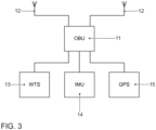
- Fig. 3 now shows the block diagram of the communication system with which the bicycle 10 is equipped.
- the wheel tick sensor 13 just delivers information about the rotational movement of the bicycle wheels. This provides information about the distance the bicycle has moved starting from a reference point.
- An inertial measurement unit 14 works by detecting the acceleration using one or more accelerometers and rotational rate using one or more gyroscopes.
- IMUs which are readily available and could also be used in bicycles. They basically measure acceleration in longitudinal and lateral direction, but also the lean angle of the bike is measured.
- IMUs which measure 6 degrees of freedom.
- a 3D compass to the IMU could be integrate to add another 3 degrees of freedom. This type of information is primarily used for the purpose of electronic traction control.
- the GPS module 15 delivers an absolute position with satellite navigation as explained above.
- the on-board unit 11 is a communication module which comprises a WLAN module or an LTE modem as indicated above.
- the on-board unit 11 comprises an LTE modem.
- This LTE modem is compliant with the specification for direct vehicle two vehicle communication LTE-V as above mentioned.
- This sort of direct V2V communication makes use of the sidelink communication direction as specified in the various LTE specifications.
- the on-board unit 11 may also be equipped with a Bluetooth communication protocol stack such that the module is capable to exchange messages with an associated Bluetooth partner station.
- the bicycle measures a position using said GPS module 15. This task is better performed at the bicycle 10 than at the portable communication device, since the bicycle may be equipped with better antennas having a better direct visual connection to the sky than what is possible with the portable device.
- Several antennas 12 for the mobile communication can also be installed on the bicycle 10 for making use of an antenna diversity technique, in particular reception diversity such as MISO technique corresponding to multiple input single output.
- the bicycle 10 takes information about the movement of the wheels by means of said wheel-tick unit 13. This can only be done on the bicycle 10 with a sensor - this is not possible on the portable communication device. Moreover, the bicycle 10 receives information about the movement and orientation / inclination via said inertia! Measurement Unit (IMU) 14 and GPS data from the GPS module 15. The bicycle 10 transmits the recorded data to the portable communication device. All this happens in step 101 of Fig. 4 .
- IMU inertia! Measurement Unit
- the smart phone evaluates the position sensor data and calculates position data for the bicycle in steps 102 and 103.
- the calculation is performed with the recorded raw data that had been collected in step 101.
- the way the smartphone calculates the bicycle position is basically a known process. E.g. smartphones and tablets are anyway capable to calculate the absolute position of the smartphone, since they are usually equipped with a navigation app, like "Google Maps", a trademark from Google Inc.
- the calculation of the position is carried out in step 103. Steps 102 and 103 are optional and will be left out if the GPS module delivers completed position data on its own.
- the portable device performs a step of map matching in step 104 with the position data to improve the position quality.
- the map matching technique maps the measured position with the map information about the location and geometry of objects in the map so that the most likely position of the object is determined in the map. Also the map matching technique is used in conventional navigation systems, such that it is referred to such state of the art solutions for further details.
- step 105 the technique of data fusion is applied on the different position data. This technique is capable of merging the different position results. With this technique the precision of the position determination is subjectively increased. Also the data fusion technique, sometimes also called “sensor fusion” is known in the state of the art. Applicant refers to the former application of the applicant with application number DE 10 2017 108 130 A1 published on 18/10/2018 for further details about the data fusion technique.
- the map matching technique requires that map data is updated frequently to perform this step with high precision.
- the data fusion technique comprises a high demand of calculation expenditure. Therefore, these steps should be better performed on the portable device than on bicycle 10.
- the finished position is sent back to the bicycle 10 in step 106.
- the bike distributes information on the finished position (see above) and dimensions of the bicycle 10 to all road users in step 107.
- This is implemented using one of the possible communication technologies that allow direct communication with the environment (802.11p, LTE-V, future 5G D2D technology).
- the distribution of that information can be done significantly better than with the portable device: As above mentioned, it can be equipped with better antennas for the V2V, D2D or car2car direct communication.
- the continuous emission of signals also requires energy. This can be provided on the bicycle more easily than on the portable device.
- the surrounding vehicles which receive the bicycle 10 position information use it to calculate on their own the bicycle trajectory.
- the trajectory describes the bicycle movement in a certain time period which typically also comprises a time period in the future such that the vehicle 20 has an estimate of where the bicycle 10 will go in order to be able to estimate the a risk of a collision.
- the bike trajectory is predicted in step 108 and the risk of a collision is calculated in step 110. If vehicle 20 recognizes a certain risk of a collision, it outputs a warning message to the driver.
- An alternative embodiment of the solution is that the vehicle automatically performs a collision avoidance maneuver without waiting for the reaction of the driver.
- the vehicle could perform a strong braking action or an emergency braking action in order to avoid a collision with the bicycle.
- the proposed method and apparatus may be implemented in various forms of hardware, software, firmware, special purpose processors, or a combination thereof.
- Special purpose processors may include application specific integrated circuits (ASICs), reduced instruction set computers (RISCs) and/or field programmable gate arrays (FPGAs).
- ASICs application specific integrated circuits
- RISCs reduced instruction set computers
- FPGAs field programmable gate arrays
- the proposed method and apparatus is implemented as a combination of hardware and software.
- the software is preferably implemented as an application program tangibly embodied on a program storage device.
- the application program may be uploaded to, and executed by, a machine comprising any suitable architecture.
- the machine is implemented on a computer platform having hardware such as one or more central processing units (CPU), a random access memory (RAM), and input/output (I/O) interface(s).
- CPU central processing units
- RAM random access memory
- I/O input/output
- the computer platform also includes an operating system and microinstruction code.
- the various processes and functions described herein may either be part of the microinstruction code or part of the application program (or a combination thereof), which is executed via the operating system.
- various other peripheral devices may be connected to the computer platform such as an additional data storage device and a printing device.
- the elements shown in the figures may be implemented in various forms of hardware, software or combinations thereof. Preferably, these elements are implemented in a combination of hardware and software on one or more appropriately programmed general-purpose devices, which may include a processor, memory and input/output interfaces.
- general-purpose devices which may include a processor, memory and input/output interfaces.
- the phrase "coupled" is defined to mean directly connected to or indirectly connected with through one or more intermediate components. Such intermediate components may include both hardware and software based components.
Landscapes
- Engineering & Computer Science (AREA)
- Physics & Mathematics (AREA)
- General Physics & Mathematics (AREA)
- Radar, Positioning & Navigation (AREA)
- Remote Sensing (AREA)
- Automation & Control Theory (AREA)
- Transportation (AREA)
- Mechanical Engineering (AREA)
- Computer Networks & Wireless Communication (AREA)
- Signal Processing (AREA)
- Human Computer Interaction (AREA)
- Traffic Control Systems (AREA)
Description
- The disclosure relates to a method for collision avoidance between a vulnerable road user vehicle and a vehicle in the vicinity. The disclosure further relates to a corresponding vulnerable road user vehicle as well as a corresponding computer program.
- In cities, there is a high risk of accidents involving cyclists. Accidents are usually caused by incorrect behavior on the part of cyclists, but also by other road users. Frequently, accidents occur in the case of incorrect or prohibited use of the road, errors in moving into the flow traffic, unadjusted speed, or incorrect behavior during turning.
- The subject application therefore is concerned with an important aspect of a safety package for vulnerable road user vehicles, e.g. bicycles. According to this concept radio messages will be sent about the position, speed, direction and other parameters such as bicycle size, lean angle, acceleration of a cyclist to the local road users in the vicinity. These messages are processed by appropriately equipped surrounding vehicles and, in the event of a danger, lead to the driver being warned or the launch of an autonomous collision avoidance maneuver when autonomous driving technology is involved. These kind of systems are already known in the automotive sector.
- From
DE 102 45 796 A1 a method of determining the current locomotion mode of a road user who is making use of a mobile telephone is known. Such method involves, that the place of the road user is successively determined on the basis of successive radiolocation instants. A vector chain of the locations as well as a vector sequence of the velocities of the mobile telephone is determined. Thereby a link of a respective place of the road user with a digital Road map, a so-called "map matching technique" is used to determine the way of locomotion of the road user. - From
DE 103 34 203 A1 a method for organizing traffic on the road is known which aims at minimizing road accidents. The position of vulnerable road users, particularly pedestrians or two-wheelers can be determined by means of the mobile phones of such road users. Core of the process according to the disclosure is that at least within an adjustable range, two traffic users moving in this range engage automatically in a direct intercommunication and inform each other about their locomotion. Through the direct and, above all, situation-based automatic intercommunication of the road users is the intermediate involvement of a control center to clear the situation superfluous. Valuable time is saved and automatic warnings as well as possible automatic interventions will be so promptly triggered, that causing an accident can be safely prevented. - From
DE 10 2008 012 655 A1 an apparatus for determining the relative position between a first and a second vehicle is known. For determining a relative position between two vehicles the position data of the adjacent vehicles with certain metadata will be transferred to the other Vehicle. The transmission occurs for example by direct vehicle-to-vehicle communication or by way of a detour via a central station. The metadata can be used to make a selection of the available satellites for the position determination in the other vehicle. In this way, it is possible to minimize the systematic errors resulting from a different selection of the satellites in the two vehicles for the position determination with GPS signals as a result. In the inner city area, where the satellite signals are not always readily receivable, the signals from a direction sensor, distance sensor and steering wheel angle sensor for the position determination can also be evaluated. - From
US 2016/086489 A1 an electric bicycle including a communication module and a computing device is known. The communication module receives vehicle information indicating a trajectory of a vehicle. The computing device compares the vehicle information to bicycle information, which represents a trajectory of the bicycle. The communication module wirelessly transmits the bicycle information to the vehicle associated with the vehicle information. A method includes generating an alert signal if the vehicle is predicted to collide with the bicycle. - From
US 2016/353241 A1 systems and techniques relating to determining a real-time position of a mobile device are known. Such systems and techniques involve a data processing apparatus which includes: one or more integrated circuit (IC) device including a location processor configured to acquire and track measurements of location for a mobile wireless communication device; and a host processor programmed with a host software manager configured to obtain various positioning input signals from different device positioning technologies and assemble a selected set of the various positioning input signals into a unified format; wherein the data processing apparatus includes a hybrid fusion engine configured to receive data from the host software manager in the unified format and calculate a position of the mobile wireless communication device using the received data in accordance with input type information for the received data. - From
US 2017/074659 A1 an approach is provided for generating location data error maps is known. The approach involves determining location data error information associated with at least one set of location data. The approach also involves causing, at least in part, an encoding of the location data error information as a function of a position parameter. The approach further involves causing, at least in part, a generation of at least one location data error map based, at least in part, on the encoding. - From
US 2015/316385 A1 a mobile device is known, which is associated with a road vehicle or the like and which has a mapping or navigation functionality configured to determine whether the vehicle is in a forwards or backwards driving mode. When a change of driving mode is detected, the mapping functionality effectively resets so that the transition between driving modes is rendered smoothly and efficiently. - In view of the prior art mentioned above, there is still a problem that the position determination, which is solely based on satellite navigation is not precise enough for the purpose of a collision avoidance in connection with vulnerable road user vehicles. E.g. the precision of the position determined with GPS signals is announced to be ± 7.5 m.
- There is therefore a need for improving the position determination method in order to increase safety for vulnerable road users. This corresponds to the problem the invention is aiming to solve.
- This object is achieved by a method for collision avoidance between a vulnerable road user vehicle and a surrounding vehicle according to claim 1, a vulnerable road user vehicle according to claim 5, and a computer program according to
claim 11. - The dependent claims include advantageous further developments and improvements of the invention as described below.
- The solution is based on an adaptation of the vulnerable road user vehicle on one hand and, in particular the exact localization of the vulnerable road user vehicle through the interaction between the vulnerable road user vehicle and a portable device of the user of the vulnerable road user vehicle, such as smartphone or tablet
An advantage is that the solution works independently of the technology used for direct V2V or D2D communication (WLAN 802.11p, LTE-V, 5G). - First of all, it is mentioned that the vulnerable road user vehicle will be equipped with at least one odometer sensor supporting an independent position determination apart from the global navigation satellite system GNSS, such as Global Positioning System GPS, Globalnaja nawigazionnaja sputnikowaja sistema GLONASS, Galileo or Beidou. Moreover, the determination of a high precision position is done by interaction between the user vehicle and portable user equipment. This interaction comprises a step of transferring position detecting sensor data to said portable communication device. A wireless communication technology could be used for this data transfer, such as Bluetooth or ZigBee communication. In said portable communication device then there is executed a step of evaluating said received position detecting sensor data and deriving position data therefrom for the vulnerable road user vehicle. In particular for the position detecting sensor data in form of odometer sensor data a step of performing a map matching technique is performed for refining the position data. It follows a step of transferring the refined position data to the vulnerable road user vehicle and in the vulnerable road user vehicle a step of distributing the refined position data to the surrounding vehicles. The surrounding vehicles can hence make use of the received position data to estimate a trajectory for the vulnerable road user vehicle, determine the risk of a collision and finally take an action to avoid a collision. This solution has several important advantages. Normally, a vulnerable road user makes use of a portable communication device such as smart phone or tablet. These portable communication devices typically are equipped with a GPS module and offer the feature of satellite navigation. They also have enough CPU power to execute evolved algorithms. On the other hand, the user vehicle is better suited for participating in direct D2D or V2V communication. E.g. it is bigger in size than the portable communication device and can be equipped with multiple antennas at different places. The places for mounting the antennas can have better direct sight to the satellites of the satellite navigation system and also to other road participants. Also it is equipped with a high capacity battery and hence can deliver enough power for a prolonged direct D2D or V2V communication phase.
- For improving safety of the user of the vulnerable road user vehicle, according to the claimed invention, a surrounding vehicle performs a step of calculating a trajectory for the vulnerable road user vehicle based on the position data received in the distribution step, determining the risk of a collision, and, if the risk of a collision exceeds a certain level, performing a collision avoidance maneuver and/or outputting a warning message to the driver of the surrounding vehicle. Such algorithms need to be installed in the vehicle anyhow if cooperative driving and/or autonomous driving shall be supported. Making autonomous collision avoidance maneuvers with the vulnerable road user vehicle is more difficult since the user is not at all protected
- An alternative solution which is also regarded as an embodiment of the invention is that not the bare position detection sensor data is transferred to the portable device, but the completed position data which is derived from the position detection sensor data. In this case, there is no need for performing the steps of evaluating the position detection sensor data and deriving the position data in the portable device.
- Another advantage measure is if the vulnerable road user vehicle is equipped with at least two different position detection sensors and in the portable communication device a step of performing a data fusion algorithm with the position data derived from the received different position detecting sensors is performed. Both helps subjectively to improve the precision of the position determination.
- For the communication between the vulnerable road user vehicle and the portable communication device
- in particular for the step of transferring the position detecting sensor data it is advantageous that it is performed by means of a short range wireless communication technique, such as Bluetooth or ZigBee. These communication systems are standardized and are readily available on the market and can be implemented without causing high costs. The user just needs to associate his portable communication device with the VRU vehicle before starting a route. This can be done automatically when a pairing has been established before.
- For a vulnerable road user vehicle, such as bicycle, motorcycle, scooter, wheel chair, or roller, it is advantageous if it comprises at least two different position detecting sensors, a communication module and an antenna module.
- It is further of advantage if said antenna module comprises at least two antennas for applying an antenna diversity technique such as MISO, corresponding to multiple input single output, SIMO, corresponding single input multiple output, or MIMO, corresponding to multiple input multiple output processing. When used in combination with diversity schemes, this improves the robustness of the communication against interferences.
- Also advantageous for improving the exactness of the position determination is if the at least two position detection sensors comprise at least two of the sensors a wheel tick sensor, an inertial measurement unit, and an absolute positioning system module such as GPS, GLONASS, Galileo or Beidou.
- Here, it is further advantageous that the communication module is capable to perform vehicle-to-vehicle communication V2V or device-to-device communication D2D according to one of the systems WLAN 802.11p corresponding to wireless LAN, LTE-V corresponding to Long Term Evolution-vehicle or 5G D2D corresponding to the 5. Generation mobile communication technology. These technologies are also specified and can be implemented without subjective research and development work.
- A corresponding computer program according to the invention, comprises program steps, which when run in a computer, carry out the steps of the portable communication device of any one of claims 1 to 4.
- This computer program is preferably implemented in the form of an app which could be installed on the portable device of the vulnerable road user, such as a smart phone or tablet computer as mentioned before.
- It is further advantageous if the computer program further comprises program steps, which, when run in the computer, carry out a step of performing a data fusion algorithm with the position data derived from the different position detecting sensors. Such data fusion algorithm causes a high demand of computing time such that this type of calculation is better executed on the portable communication device which if it comes in the form of a smartphone or tablet is equipped with a powerful central processing unit CPU.
- In this case, the absolute position data indicate the measured position of the vulnerable road user vehicle at a certain time in absolute values, for example in a UTM or WGS84 reference coordinate system. Optionally, the absolute position data may also be provided with an orientation, e.g. a current direction of movement of the vulnerable road user vehicle. A combination of position and orientation is often referred to as a pose. The position is usually expressed two-dimensionally in a Cartesian coordinate system.
- The odometry position data, on the other hand, indicate a self-movement or relative movement of the vulnerable road user vehicle, for example in an arbitrarily defined reference coordinate system or in the so-called vehicle coordinate system ("body frame"). In this case, the self-movement, is indicated in each case relative to a preceding position of the vulnerable road user vehicle.
- Corresponding advantages are apparent for a user according to the proposal and a computer program according to the proposal as claimed.
- An exemplary embodiment of the invention is illustrated in the drawings and is explained in more detail below with reference to the figures.
-
- Fig. 1
- an illustration of a typical traffic situation where a vulnerable road user vehicle crosses the path of a surrounding bigger vehicle;
- Fig. 2
- a bicycle corresponding to a vulnerable road user vehicle equipped with additional components according to the proposal;
- Fig. 3
- a block diagram for the electronic components of a vulnerable road user vehicle according to the proposal; and
- Fig. 4
- an illustration of the process for collision avoidance according to the proposal.
- The present description illustrates the principles of the present disclosure. It will thus be appreciated that those skilled in the art will be able to devise various arrangements that, although not explicitly described or shown herein, embody the principles of the disclosure.
- All examples and conditional language recited herein are intended for educational purposes to aid the reader in understanding the principles of the disclosure and the concepts contributed by the inventor to furthering the art, and are to be construed as being without limitation to such specifically recited examples and conditions.
- Thus, for example, it will be appreciated by those skilled in the art that the diagrams presented herein represent conceptual views of illustrative circuitry embodying the principles of the disclosure.
- The functions of the various elements shown in the figures may be provided through the use of dedicated hardware as well as hardware capable of executing software in association with appropriate software. When provided by a processor, the functions may be provided by a single dedicated processor, by a single shared processor, or by a plurality of individual processors, some of which may be shared. Moreover, explicit use of the term "processor" or "controller" should not be construed to refer exclusively to hardware capable of executing software, and may implicitly include, without limitation, digital signal processor (DSP) hardware, read only memory (ROM) for storing software, random access memory (RAM), and nonvolatile storage.
- Other hardware, conventional and/or custom, may also be included. Similarly, any switches shown in the figures are conceptual only. Their function may be carried out through the operation of program logic, through dedicated logic, through the interaction of program control and dedicated logic, or even manually, the particular technique being selectable by the implementer as more specifically understood from the context.
- In the claims hereof, any element expressed as a means for performing a specified function is intended to encompass any way of performing that function including, for example, a) a combination of circuit elements that performs that function or b) software in any form, including, therefore, firmware, microcode or the like, combined with appropriate circuitry for executing that software to perform the function. The disclosure as defined by such claims resides in the fact that the functionalities provided by the various recited means are combined and brought together in the manner which the claims call for.
-
Fig. 1 shows a typical traffic situation where a vulnerable road user vehicle is involved. The vulnerable road user vehicle is exemplified as a bicycle and labelled withreference number 10. A bicycle is only one example of a vulnerable road user vehicle. Other examples are a motorcycle, a scooter, a wheel chair, or a roller. The listing is not exhaustive and there exist further variants, e.g. a Segway Personal Transporter, or a Self-Balancing Unicycle and more. - Another vehicle is labeled with
reference number 20. That vehicle is a bigger size vehicle with 3, 4 or more wheels. The term vehicle is to be understood as a collective term for motor vehicles with an internal combustion engine or an electric motor. Whether for passenger cars, trucks, buses, agricultural vehicles or construction machines. The list is not exhaustive and includes other vehicle categories. - For these types of vehicles there exist a plurality of communication techniques. Vehicles participate in mobile communication since long, and now with cooperative or autonomous driving technologies arising there is also a focus on vehicle direct communication, which is necessary for this purpose. Various systems for vehicle communication are developed. Examples include WLAN-based vehicle communication, also called "ad-hoc domain", and vehicle communication in the field of mobile radio networks. In the case of mobile radio-based technology, however, the base station has to transmit the messages from vehicle to vehicle. This is the area where communication takes place in the so-called "Infrastructure Domain". For the future mobile radio generation, the vehicle direct communication is also made possible. In LTE, according to Long Term Evolution, this variant is called LTE-V corresponding to LTE vehicle, and in the case of the 5G initiative this variant is often called D2D for device two device communication.
-
Such vehicles 20 are equipped with a communication module, which serves as a transmitting and receiving unit for communication in a mobile radio network. All messages from the vehicle 20 (uplink) and to the vehicle 20 (downlink) are routed either via abase station 30 which serves a mobile radio cell or, in the case of direct vehicle communication (Sidelink), directly between a plurality of thevehicles 20. If thevehicles 20 are within this mobile radio cell, they are registered or logged in at thebase station 30. If they leave the mobile cell, they are handed over to the neighboring cell (handover) and accordingly logged out or logged off at thebase station 30. Thebase station 30 also provides access to the Internet so that thevehicles 20 or all other mobile radio subscribers are supplied with Internet data in the mobile radio cell. - Such mobile radio technologies are standardized and reference is made here to the corresponding specifications of mobile radio standards. As a modern example of a mobile radio standard, reference is made to the 3GPP initiative and the LTE standard (Long Term Evolution). Many of the related ETSI specifications are currently available in the
version 14. The following is mentioned as an example: ETSI TS 136 213 V13.0.0 (2016-05); Evolved Universal Terrestrial Radio Access (E-UTRA); Physical layer procedures (3GPP TS 36.213 version 13.0.0 Release 13). -
Fig. 2 shows an example of abicycle 10 which is enhanced with communication technology for the purpose of the proposal. The reference numbers shown inFig. 2 denote an on-board communication unit 11, twoantennas 12 one mounted at the rear end of the bicycle and the other at the front of the bicycle, a wheeltick unit WTU 13, aGPS module 15 and abattery 16. In the example shown inFig. 2 , the bicycle corresponds to an e-bike equipped with anelectric motor 17. Thebattery 16 therefore is rechargeable and the capacity of thebattery 16 is big. -
Fig. 3 now shows the block diagram of the communication system with which thebicycle 10 is equipped. Here, it is noted that the same components are labelled with the identical reference numbers which are also used inFig. 2 . Thewheel tick sensor 13 just delivers information about the rotational movement of the bicycle wheels. This provides information about the distance the bicycle has moved starting from a reference point. Aninertial measurement unit 14 works by detecting the acceleration using one or more accelerometers and rotational rate using one or more gyroscopes. For motorbikes there exist IMUs which are readily available and could also be used in bicycles. They basically measure acceleration in longitudinal and lateral direction, but also the lean angle of the bike is measured. There exist IMUs which measure 6 degrees of freedom. To further add precision a 3D compass to the IMU could be integrate to add another 3 degrees of freedom. This type of information is primarily used for the purpose of electronic traction control. TheGPS module 15 delivers an absolute position with satellite navigation as explained above. - The on-
board unit 11 is a communication module which comprises a WLAN module or an LTE modem as indicated above. - In the following it is assumed that the on-
board unit 11 comprises an LTE modem. This LTE modem is compliant with the specification for direct vehicle two vehicle communication LTE-V as above mentioned. This sort of direct V2V communication makes use of the sidelink communication direction as specified in the various LTE specifications. The on-board unit 11 may also be equipped with a Bluetooth communication protocol stack such that the module is capable to exchange messages with an associated Bluetooth partner station. - The method for collision avoidance is now described with the help of
Fig. 4 . - At the beginning, the cyclist connects his mobile phone to the
bicycle 10 via Bluetooth communication. This corresponds to the well-known Bluetooth association process. Bicycle and smartphone can communicate continuously. In the following we describe the collision avoidance procedure: - The bicycle measures a position using said
GPS module 15. This task is better performed at thebicycle 10 than at the portable communication device, since the bicycle may be equipped with better antennas having a better direct visual connection to the sky than what is possible with the portable device.Several antennas 12 for the mobile communication can also be installed on thebicycle 10 for making use of an antenna diversity technique, in particular reception diversity such as MISO technique corresponding to multiple input single output. - The
bicycle 10 takes information about the movement of the wheels by means of said wheel-tick unit 13. This can only be done on thebicycle 10 with a sensor - this is not possible on the portable communication device. Moreover, thebicycle 10 receives information about the movement and orientation / inclination via said inertia! Measurement Unit (IMU) 14 and GPS data from theGPS module 15. Thebicycle 10 transmits the recorded data to the portable communication device. All this happens instep 101 ofFig. 4 . - The smart phone evaluates the position sensor data and calculates position data for the bicycle in
steps step 101. The way the smartphone calculates the bicycle position is basically a known process. E.g. smartphones and tablets are anyway capable to calculate the absolute position of the smartphone, since they are usually equipped with a navigation app, like "Google Maps", a trademark from Google Inc. The calculation of the position is carried out instep 103.Steps - The portable device performs a step of map matching in
step 104 with the position data to improve the position quality. The map matching technique maps the measured position with the map information about the location and geometry of objects in the map so that the most likely position of the object is determined in the map. Also the map matching technique is used in conventional navigation systems, such that it is referred to such state of the art solutions for further details. - The different sensor systems, odometry with WTS and IMU sensor and GPS deliver different results for the bicycle position. Both position results are subject to errors. In
step 105 then the technique of data fusion is applied on the different position data. This technique is capable of merging the different position results. With this technique the precision of the position determination is subjectively increased. Also the data fusion technique, sometimes also called "sensor fusion" is known in the state of the art. Applicant refers to the former application of the applicant withapplication number DE 10 2017 108 130 A1 published on 18/10/2018 for further details about the data fusion technique. - The map matching technique requires that map data is updated frequently to perform this step with high precision. The data fusion technique comprises a high demand of calculation expenditure. Therefore, these steps should be better performed on the portable device than on
bicycle 10. - The finished position is sent back to the
bicycle 10 instep 106. - The bike distributes information on the finished position (see above) and dimensions of the
bicycle 10 to all road users instep 107. This is implemented using one of the possible communication technologies that allow direct communication with the environment (802.11p, LTE-V, future 5G D2D technology). The distribution of that information can be done significantly better than with the portable device: As above mentioned, it can be equipped with better antennas for the V2V, D2D or car2car direct communication. Furthermore, the continuous emission of signals also requires energy. This can be provided on the bicycle more easily than on the portable device. - The surrounding vehicles which receive the
bicycle 10 position information use it to calculate on their own the bicycle trajectory. The trajectory describes the bicycle movement in a certain time period which typically also comprises a time period in the future such that thevehicle 20 has an estimate of where thebicycle 10 will go in order to be able to estimate the a risk of a collision. The bike trajectory is predicted instep 108 and the risk of a collision is calculated instep 110. Ifvehicle 20 recognizes a certain risk of a collision, it outputs a warning message to the driver. An alternative embodiment of the solution is that the vehicle automatically performs a collision avoidance maneuver without waiting for the reaction of the driver. Here, the vehicle could perform a strong braking action or an emergency braking action in order to avoid a collision with the bicycle. - A good overview about different ways to calculate such collision avoiding maneuver is described in a thesis report of Dr. Thomas Maurer titled "Bewertung von Mess- und Prädiktionsunsicherheiten in der zeitlichen Eingriffsentscheidung für automatische Notbrems- und Ausweichsysteme" at University Duisburg-Essen. Another detailed example of such a system is described in the pending application of the applicant with the number
EP 3 457 382 A1 published on 20/03/2019 . - It is to be understood that the proposed method and apparatus may be implemented in various forms of hardware, software, firmware, special purpose processors, or a combination thereof. Special purpose processors may include application specific integrated circuits (ASICs), reduced instruction set computers (RISCs) and/or field programmable gate arrays (FPGAs). Preferably, the proposed method and apparatus is implemented as a combination of hardware and software. Moreover, the software is preferably implemented as an application program tangibly embodied on a program storage device. The application program may be uploaded to, and executed by, a machine comprising any suitable architecture. Preferably, the machine is implemented on a computer platform having hardware such as one or more central processing units (CPU), a random access memory (RAM), and input/output (I/O) interface(s). The computer platform also includes an operating system and microinstruction code. The various processes and functions described herein may either be part of the microinstruction code or part of the application program (or a combination thereof), which is executed via the operating system. In addition, various other peripheral devices may be connected to the computer platform such as an additional data storage device and a printing device.
- It should be understood that the elements shown in the figures may be implemented in various forms of hardware, software or combinations thereof. Preferably, these elements are implemented in a combination of hardware and software on one or more appropriately programmed general-purpose devices, which may include a processor, memory and input/output interfaces. Herein, the phrase "coupled" is defined to mean directly connected to or indirectly connected with through one or more intermediate components. Such intermediate components may include both hardware and software based components.
- It is to be further understood that, because some of the constituent system components and method steps depicted in the accompanying figures are preferably implemented in software, the actual connections between the system components (or the process steps) may differ depending upon the manner in which the proposed method and apparatus is programmed. Given the teachings herein, one of ordinary skill in the related art will be able to contemplate these and similar implementations or configurations of the proposed method and apparatus.
-
- 10
- Bicycle
- 11
- On-Board Unit
- 12
- Antenna
- 13
- Wheel Tick Sensor
- 14
- IMU Module
- 15
- GPS Module
- 16
- Battery
- 20
- Surrounding Vehicle
- 101
- Step Of Transferring Position Detecting Sensor Data
- 102
- Step Of Evaluating The Position Detecting Sensor Data
- 103
- Step Of Deriving Position Data
- 104
- Step Of Performing A Map Matching Technique
- 105
- Step Of Performing A Data Fusion Technique
- 106
- Step Of Transferring High Precision Position Data
- 107
- Step Of Distributing High Precision Position Data
- 108
- Step Of Calculating A Trajectory For The Vulnerable Road User Vehicle
- 109
- Step Of Determining a Risk of a Collision
- 110
- Step Of Warning The Driver Of The Surrounding Vehicle
Claims (11)
- A method for collision avoidance between a vulnerable road user vehicle (10) and a surrounding vehicle (20), wherein the user of the vulnerable road user vehicle (10) makes use of a portable communication device, the method comprising the steps of:- in said vulnerable road user vehicle, transferring (101) position detecting sensor data or position data derived therefrom to said portable communication device,- in said portable communication device, evaluating (102) said position detecting sensor data and deriving (103) position data for the vulnerable road user vehicle (10) in case position detecting sensor data are transferred (101) to the portable communication device, performing (104) a map matching technique for refining the position data, and transferring (106) the refined position data to the vulnerable road user vehicle (10),- in the vulnerable road user vehicle (10), distributing (107) the refined position data to the surrounding vehicle (20), and- in the surrounding vehicle (20), predicting (108) a trajectory for the vulnerable road user vehicle (10) based on the position data received in the distribution step (107), determining (109) a risk of a collision, and, if the risk of a collision exceeds a certain level performing a collision avoidance maneuver and/or outputting (108) a warning message to the driver of the surrounding vehicle (20).
- The method according to claim 1, wherein the vulnerable road user vehicle (10) is equipped with at least two different position detection sensors (13, 14, 15), and wherein the method further comprises a step of performing (105) a data fusion algorithm in the portable communication device with the position data derived from the received different position detecting sensors (13, 14, 15).
- The method according to claim 1 or 2, wherein the step of transferring (101) the position detecting sensor data is performed by means of a short range wireless communication technique.
- The method according to claim 3, wherein the short range wireless communication technique corresponds to one of the communication techniques Bluetooth or ZigBee.
- A vulnerable road user vehicle (10) comprising at least two different position detecting sensors (13 14, 15), a communication module (11), and an antenna module, wherein the vulnerable road user vehicle (10) further comprises processing means adapted to perform the method steps of said vulnerable road user vehicle (10) in one of the previous claims.
- The vulnerable road user vehicle (10) according to claim 5, wherein the vulnerable road user vehicle (10) is a bicycle, a motorcycle, a scooter, a wheel chair, or a roller.
- The vulnerable road user vehicle (10) according to claim 5 or 6, wherein said antenna module comprises at least two antennas (12) for applying an antenna diversity technique in the form of at least one of the techniques MISO, corresponding to multiple input single output, SIMO, corresponding single input multiple output, or MIMO, corresponding to multiple input multiple output processing.
- The vulnerable road user vehicle (10) according to one of claims 5 to 7, wherein the at least two position detection sensors (13, 14, 15) comprise at least two of a wheel tick sensor (WTS), an inertial measurement unit (IMU), and an absolute positioning system module (GPS).
- The vulnerable road user vehicle (10) according to claim 8, wherein the absolute positioning system module (GPS) corresponds to at least one of the systems global positioning system GPS, GLONASS, Galileo or Beidou.
- The vulnerable road user vehicle (10) according to one of claims 5 to 9, wherein the communication module (11) is capable of performing vehicle-to-vehicle communication V2V or device-to-device communication D2D according to one of the systems WLAN 802.11p, corresponding to wireless LAN, LTE-V, corresponding to Long Term Evolution-vehicle, or 5G D2D, corresponding to the 5th Generation mobile communication technology.
- A computer program, characterized in that the computer program comprises program steps, which, when run in a computer, carry out the steps of the method for the portable communication device in one of claims 1 to 4.
Priority Applications (3)
| Application Number | Priority Date | Filing Date | Title |
|---|---|---|---|
| EP17196570.0A EP3471075B1 (en) | 2017-10-16 | 2017-10-16 | Method for collision avoidance between a vulnerable road user vehicle and a surrounding vehicle, vulnerable road user vehicle, further vehicle and computer program |
| US16/153,864 US11046308B2 (en) | 2017-10-16 | 2018-10-08 | Method for collision avoidance between a vulnerable road user transportation vehicle and a surrounding transportation vehicle, vulnerable road user transportation vehicle, further transportation vehicle, and computer program |
| CN201811188008.XA CN109671297A (en) | 2017-10-16 | 2018-10-12 | Avoid collision method, road user vehicle, other vehicles and computer program |
Applications Claiming Priority (1)
| Application Number | Priority Date | Filing Date | Title |
|---|---|---|---|
| EP17196570.0A EP3471075B1 (en) | 2017-10-16 | 2017-10-16 | Method for collision avoidance between a vulnerable road user vehicle and a surrounding vehicle, vulnerable road user vehicle, further vehicle and computer program |
Publications (2)
| Publication Number | Publication Date |
|---|---|
| EP3471075A1 EP3471075A1 (en) | 2019-04-17 |
| EP3471075B1 true EP3471075B1 (en) | 2025-01-15 |
Family
ID=60161948
Family Applications (1)
| Application Number | Title | Priority Date | Filing Date |
|---|---|---|---|
| EP17196570.0A Active EP3471075B1 (en) | 2017-10-16 | 2017-10-16 | Method for collision avoidance between a vulnerable road user vehicle and a surrounding vehicle, vulnerable road user vehicle, further vehicle and computer program |
Country Status (3)
| Country | Link |
|---|---|
| US (1) | US11046308B2 (en) |
| EP (1) | EP3471075B1 (en) |
| CN (1) | CN109671297A (en) |
Families Citing this family (26)
| Publication number | Priority date | Publication date | Assignee | Title |
|---|---|---|---|---|
| US10730514B2 (en) * | 2018-09-12 | 2020-08-04 | Toyota Motor Engineering & Manufacturing North America, Inc. | Systems and methods for extending detachable automobile sensor capabilities for collision avoidance |
| US11124185B2 (en) | 2018-11-13 | 2021-09-21 | Zoox, Inc. | Perception collision avoidance |
| US11104332B2 (en) * | 2018-12-12 | 2021-08-31 | Zoox, Inc. | Collision avoidance system with trajectory validation |
| US12530970B2 (en) | 2018-12-26 | 2026-01-20 | Zoox, Inc. | Collision avoidance system |
| US11570625B2 (en) * | 2019-03-25 | 2023-01-31 | Micron Technology, Inc. | Secure vehicle communications architecture for improved blind spot and driving distance detection |
| CN110285806A (en) * | 2019-07-05 | 2019-09-27 | 电子科技大学 | Fast and precise positioning algorithm for mobile robot based on multiple pose correction |
| CN110769054A (en) * | 2019-10-22 | 2020-02-07 | 广东技术师范大学 | Intelligent traffic monitoring platform and method based on Internet of things |
| EP4073780A4 (en) | 2019-12-12 | 2024-04-17 | INTEL Corporation | Vulnerable road user safety technologies based on responsibility sensitive safety |
| US10902727B1 (en) | 2019-12-18 | 2021-01-26 | Honda Motor Co., Ltd. | Parked vehicle warning infrastructure |
| CN111243274A (en) * | 2020-01-20 | 2020-06-05 | 陈俊言 | Road collision early warning system and method for non-internet traffic individuals |
| CN115210776B (en) * | 2020-03-03 | 2025-05-27 | 瑞典爱立信有限公司 | Object position information supply for autonomous vehicle maneuvers |
| US12038297B2 (en) * | 2020-03-26 | 2024-07-16 | Toyota Motor Engineering & Manufacturing North America, Inc. | Remote control of vehicle via smartphone and gesture input |
| EP3988370A1 (en) | 2020-10-23 | 2022-04-27 | Robert Bosch GmbH | Methods, control unit, personal mobile terminal, lightweight vehicle, and system |
| EP3989608A1 (en) * | 2020-10-23 | 2022-04-27 | Robert Bosch GmbH | Methods, apparatus, and system |
| DE102021201910A1 (en) * | 2021-03-01 | 2022-09-01 | Continental Teves Ag & Co. Ohg | Method and device for securing the content of object data for collective perception |
| EP4112411B1 (en) * | 2021-07-01 | 2024-03-27 | Zenseact AB | Estimation of accident intensity for vehicles |
| US20230059897A1 (en) * | 2021-08-12 | 2023-02-23 | Lear Corporation | System and method for vehicle-to-everything (v2x) collaborative perception |
| EP4164308A1 (en) | 2021-10-07 | 2023-04-12 | Volkswagen Aktiengesellschaft | Methods for user equipment for improving position information, apparatus, vehicle and computer program |
| DE102021212360A1 (en) * | 2021-11-03 | 2023-05-04 | Robert Bosch Gesellschaft mit beschränkter Haftung | Method for detecting a change of direction in a single-track vehicle |
| US12078738B2 (en) | 2021-11-09 | 2024-09-03 | Msrs Llc | Method, apparatus, and computer readable medium for a multi-source reckoning system |
| EP4181540A1 (en) | 2021-11-10 | 2023-05-17 | Robert Bosch GmbH | Methods, apparatus, and lightweight vehicles |
| US12108696B2 (en) * | 2021-12-23 | 2024-10-08 | Cnh Industrial America Llc | Agricultural system and method for determining an as-driven path of an agricultural work vehicle |
| US20230339394A1 (en) * | 2022-04-22 | 2023-10-26 | Velo.Ai, Inc | Artificially intelligent mobility safety system |
| DE102022212869B3 (en) | 2022-11-30 | 2024-03-28 | Volkswagen Aktiengesellschaft | Method for operating at least one autonomously operated vehicle, vehicle guidance system, and vehicle |
| US20250034912A1 (en) * | 2023-07-28 | 2025-01-30 | Volvo Car Corporation | Door lock for cyclist protection |
| US12259246B1 (en) | 2024-05-13 | 2025-03-25 | Msrs Llc | Method, apparatus, and computer readable medium for calculating a handrail influence intensity factor |
Family Cites Families (24)
| Publication number | Priority date | Publication date | Assignee | Title |
|---|---|---|---|---|
| DE10245796A1 (en) | 2002-10-01 | 2004-04-15 | Daimlerchrysler Ag | Determining movement mode of road user carrying mobile telephone, for traffic forecasting or reconstruction, by linking locations determined at sequential times to digital road map |
| DE10334203A1 (en) | 2003-07-26 | 2005-03-10 | Volkswagen Ag | Interactive traffic handling method, by informing respective road users of current movements of other road users by direct intercommunication |
| DE102008012655A1 (en) | 2007-05-30 | 2008-12-04 | Continental Teves Ag & Co. Ohg | Relative position determination of vehicles |
| US7932820B2 (en) * | 2007-07-21 | 2011-04-26 | I Did It Inc. | High visibility safety helmet system |
| WO2012129425A2 (en) * | 2011-03-23 | 2012-09-27 | Tk Holdings Inc. | Driver assistance system |
| FR2996512B1 (en) * | 2012-10-05 | 2014-11-21 | Renault Sa | METHOD FOR EVALUATING THE RISK OF COLLISION AT AN INTERSECTION |
| GB201219799D0 (en) * | 2012-11-02 | 2012-12-19 | Tomtom Int Bv | Map Matching methods |
| US10037689B2 (en) * | 2015-03-24 | 2018-07-31 | Donald Warren Taylor | Apparatus and system to manage monitored vehicular flow rate |
| US9641973B2 (en) * | 2013-12-12 | 2017-05-02 | Marvell World Trade Ltd. | Method and apparatus for tracking, in real-time, a position of a mobile wireless communication device |
| US9704132B2 (en) * | 2014-01-11 | 2017-07-11 | Federico Fraccaroli | Method, system and apparatus for adapting the functionalities of a connected object associated with a user ID |
| US20160086489A1 (en) * | 2014-09-23 | 2016-03-24 | Ford Global Technologies, Llc | E-bike to infrastructure or vehicle communication |
| US20160357262A1 (en) * | 2015-06-05 | 2016-12-08 | Arafat M.A. ANSARI | Smart vehicle |
| US20160357187A1 (en) * | 2015-06-05 | 2016-12-08 | Arafat M.A. ANSARI | Smart vehicle |
| US9711050B2 (en) * | 2015-06-05 | 2017-07-18 | Bao Tran | Smart vehicle |
| US20210272207A1 (en) * | 2015-08-28 | 2021-09-02 | State Farm Mutual Automobile Insurance Company | Vehicular driver profiles and discounts |
| US9684081B2 (en) * | 2015-09-16 | 2017-06-20 | Here Global B.V. | Method and apparatus for providing a location data error map |
| US10303166B2 (en) * | 2016-05-23 | 2019-05-28 | nuTonomy Inc. | Supervisory control of vehicles |
| TWI662252B (en) * | 2016-09-06 | 2019-06-11 | 財團法人工業技術研究院 | Roadside detection system, roadside unit and roadside communication method thereof |
| WO2018079297A1 (en) * | 2016-10-27 | 2018-05-03 | 日立オートモティブシステムズ株式会社 | Malfunction detecting device |
| DE102017108130B4 (en) | 2017-04-13 | 2024-02-29 | Volkswagen Aktiengesellschaft | Method for data fusion of a data set, corresponding computing unit and vehicle which is equipped with a corresponding computing unit and computer program |
| CN107200016B (en) * | 2017-05-26 | 2019-11-08 | 重庆长安汽车股份有限公司 | Road adaptive forecasting method and the Vehicular system for using this method |
| US20180364708A1 (en) * | 2017-06-16 | 2018-12-20 | GM Global Technology Operations LLC | Automated vehicle route traversal capability |
| US10455882B2 (en) * | 2017-09-29 | 2019-10-29 | Honda Motor Co., Ltd. | Method and system for providing rear collision warning within a helmet |
| TWI657945B (en) * | 2018-01-26 | 2019-05-01 | 宏佳騰動力科技股份有限公司 | Locomotive accident detection and notification method |
-
2017
- 2017-10-16 EP EP17196570.0A patent/EP3471075B1/en active Active
-
2018
- 2018-10-08 US US16/153,864 patent/US11046308B2/en active Active
- 2018-10-12 CN CN201811188008.XA patent/CN109671297A/en active Pending
Also Published As
| Publication number | Publication date |
|---|---|
| US11046308B2 (en) | 2021-06-29 |
| US20190111921A1 (en) | 2019-04-18 |
| EP3471075A1 (en) | 2019-04-17 |
| CN109671297A (en) | 2019-04-23 |
Similar Documents
| Publication | Publication Date | Title |
|---|---|---|
| US11046308B2 (en) | Method for collision avoidance between a vulnerable road user transportation vehicle and a surrounding transportation vehicle, vulnerable road user transportation vehicle, further transportation vehicle, and computer program | |
| US11814064B2 (en) | Method, apparatus, electronic device, computer program and computer readable recording medium for measuring inter-vehicle distance using driving image | |
| US10431082B2 (en) | Systems and methods for emergency vehicle response in an autonomous vehicle | |
| US10481600B2 (en) | Systems and methods for collaboration between autonomous vehicles | |
| US20210132604A1 (en) | Autonomous passenger vehicle system | |
| US11395117B2 (en) | Vehicle emergency V2X notification based on sensor fusion | |
| US20190232954A1 (en) | Systems and methods for collision detection in autonomous vehicles | |
| US20180113204A1 (en) | Systems and methods for aligning an inertial measurement unit in a vehicle | |
| EP3678353B1 (en) | Matching a first connected device with a second connected device based on vehicle-to-everything v2x message variables | |
| US20200324762A1 (en) | Transportation vehicle and collision avoidance method | |
| WO2018128946A1 (en) | Method for providing vulnerable road user warnings in a blind spot of a parked vehicle | |
| CN111339445A (en) | System and method for vehicle-based touring | |
| US10536815B2 (en) | Tracking a wireless device using a seamless handoff between a vehicle and a mobile device | |
| US20180373254A1 (en) | Autonomous vehicle localization | |
| US20230182843A1 (en) | Method For Detection Of An Object Near A Road User | |
| US20140316690A1 (en) | Device and method for determining the position of a vehicle | |
| CN116195279A (en) | Data transmission device, data transmission method, and data transmission program | |
| JP6536445B2 (en) | Vehicle communication control device | |
| US20210185587A1 (en) | Mobile mesh network provisioning systems and methods | |
| KR20180076913A (en) | Driver assistance apparatus | |
| CN108428366B (en) | Driving assisting method and device | |
| US12387606B2 (en) | Systems and methods for personal mobile vehicle localization in a fleet management system | |
| JP2014215759A (en) | Driving assist unit, driving assist apparatus, sensor unit, and portable terminal | |
| CN114582147A (en) | Reversing operation detection system and method | |
| JP2004284494A (en) | Position detection device, parking support system, on-vehicle terminal, control method of on-vehicle terminal, server computer, and control method of server computer |
Legal Events
| Date | Code | Title | Description |
|---|---|---|---|
| PUAI | Public reference made under article 153(3) epc to a published international application that has entered the european phase |
Free format text: ORIGINAL CODE: 0009012 |
|
| STAA | Information on the status of an ep patent application or granted ep patent |
Free format text: STATUS: THE APPLICATION HAS BEEN PUBLISHED |
|
| AK | Designated contracting states |
Kind code of ref document: A1 Designated state(s): AL AT BE BG CH CY CZ DE DK EE ES FI FR GB GR HR HU IE IS IT LI LT LU LV MC MK MT NL NO PL PT RO RS SE SI SK SM TR |
|
| AX | Request for extension of the european patent |
Extension state: BA ME |
|
| STAA | Information on the status of an ep patent application or granted ep patent |
Free format text: STATUS: REQUEST FOR EXAMINATION WAS MADE |
|
| 17P | Request for examination filed |
Effective date: 20191017 |
|
| RBV | Designated contracting states (corrected) |
Designated state(s): AL AT BE BG CH CY CZ DE DK EE ES FI FR GB GR HR HU IE IS IT LI LT LU LV MC MK MT NL NO PL PT RO RS SE SI SK SM TR |
|
| STAA | Information on the status of an ep patent application or granted ep patent |
Free format text: STATUS: EXAMINATION IS IN PROGRESS |
|
| 17Q | First examination report despatched |
Effective date: 20210609 |
|
| GRAP | Despatch of communication of intention to grant a patent |
Free format text: ORIGINAL CODE: EPIDOSNIGR1 |
|
| STAA | Information on the status of an ep patent application or granted ep patent |
Free format text: STATUS: GRANT OF PATENT IS INTENDED |
|
| INTG | Intention to grant announced |
Effective date: 20240812 |
|
| GRAS | Grant fee paid |
Free format text: ORIGINAL CODE: EPIDOSNIGR3 |
|
| GRAA | (expected) grant |
Free format text: ORIGINAL CODE: 0009210 |
|
| STAA | Information on the status of an ep patent application or granted ep patent |
Free format text: STATUS: THE PATENT HAS BEEN GRANTED |
|
| P01 | Opt-out of the competence of the unified patent court (upc) registered |
Free format text: CASE NUMBER: APP_63977/2024 Effective date: 20241203 |
|
| AK | Designated contracting states |
Kind code of ref document: B1 Designated state(s): AL AT BE BG CH CY CZ DE DK EE ES FI FR GB GR HR HU IE IS IT LI LT LU LV MC MK MT NL NO PL PT RO RS SE SI SK SM TR |
|
| REG | Reference to a national code |
Ref country code: CH Ref legal event code: EP Ref country code: GB Ref legal event code: FG4D |
|
| REG | Reference to a national code |
Ref country code: DE Ref legal event code: R096 Ref document number: 602017087321 Country of ref document: DE |
|
| REG | Reference to a national code |
Ref country code: IE Ref legal event code: FG4D |
|
| REG | Reference to a national code |
Ref country code: NL Ref legal event code: MP Effective date: 20250115 |
|
| PG25 | Lapsed in a contracting state [announced via postgrant information from national office to epo] |
Ref country code: NL Free format text: LAPSE BECAUSE OF FAILURE TO SUBMIT A TRANSLATION OF THE DESCRIPTION OR TO PAY THE FEE WITHIN THE PRESCRIBED TIME-LIMIT Effective date: 20250115 |
|
| PG25 | Lapsed in a contracting state [announced via postgrant information from national office to epo] |
Ref country code: RS Free format text: LAPSE BECAUSE OF FAILURE TO SUBMIT A TRANSLATION OF THE DESCRIPTION OR TO PAY THE FEE WITHIN THE PRESCRIBED TIME-LIMIT Effective date: 20250415 |
|
| PG25 | Lapsed in a contracting state [announced via postgrant information from national office to epo] |
Ref country code: FI Free format text: LAPSE BECAUSE OF FAILURE TO SUBMIT A TRANSLATION OF THE DESCRIPTION OR TO PAY THE FEE WITHIN THE PRESCRIBED TIME-LIMIT Effective date: 20250115 |
|
| PG25 | Lapsed in a contracting state [announced via postgrant information from national office to epo] |
Ref country code: PL Free format text: LAPSE BECAUSE OF FAILURE TO SUBMIT A TRANSLATION OF THE DESCRIPTION OR TO PAY THE FEE WITHIN THE PRESCRIBED TIME-LIMIT Effective date: 20250115 |
|
| PG25 | Lapsed in a contracting state [announced via postgrant information from national office to epo] |
Ref country code: ES Free format text: LAPSE BECAUSE OF FAILURE TO SUBMIT A TRANSLATION OF THE DESCRIPTION OR TO PAY THE FEE WITHIN THE PRESCRIBED TIME-LIMIT Effective date: 20250115 |
|
| REG | Reference to a national code |
Ref country code: LT Ref legal event code: MG9D |
|
| PG25 | Lapsed in a contracting state [announced via postgrant information from national office to epo] |
Ref country code: NO Free format text: LAPSE BECAUSE OF FAILURE TO SUBMIT A TRANSLATION OF THE DESCRIPTION OR TO PAY THE FEE WITHIN THE PRESCRIBED TIME-LIMIT Effective date: 20250415 Ref country code: IS Free format text: LAPSE BECAUSE OF FAILURE TO SUBMIT A TRANSLATION OF THE DESCRIPTION OR TO PAY THE FEE WITHIN THE PRESCRIBED TIME-LIMIT Effective date: 20250515 |
|
| REG | Reference to a national code |
Ref country code: AT Ref legal event code: MK05 Ref document number: 1760368 Country of ref document: AT Kind code of ref document: T Effective date: 20250115 |
|
| PG25 | Lapsed in a contracting state [announced via postgrant information from national office to epo] |
Ref country code: HR Free format text: LAPSE BECAUSE OF FAILURE TO SUBMIT A TRANSLATION OF THE DESCRIPTION OR TO PAY THE FEE WITHIN THE PRESCRIBED TIME-LIMIT Effective date: 20250115 |
|
| PG25 | Lapsed in a contracting state [announced via postgrant information from national office to epo] |
Ref country code: PT Free format text: LAPSE BECAUSE OF FAILURE TO SUBMIT A TRANSLATION OF THE DESCRIPTION OR TO PAY THE FEE WITHIN THE PRESCRIBED TIME-LIMIT Effective date: 20250515 Ref country code: LV Free format text: LAPSE BECAUSE OF FAILURE TO SUBMIT A TRANSLATION OF THE DESCRIPTION OR TO PAY THE FEE WITHIN THE PRESCRIBED TIME-LIMIT Effective date: 20250115 |
|
| PG25 | Lapsed in a contracting state [announced via postgrant information from national office to epo] |
Ref country code: GR Free format text: LAPSE BECAUSE OF FAILURE TO SUBMIT A TRANSLATION OF THE DESCRIPTION OR TO PAY THE FEE WITHIN THE PRESCRIBED TIME-LIMIT Effective date: 20250416 Ref country code: BG Free format text: LAPSE BECAUSE OF FAILURE TO SUBMIT A TRANSLATION OF THE DESCRIPTION OR TO PAY THE FEE WITHIN THE PRESCRIBED TIME-LIMIT Effective date: 20250115 |
|
| PG25 | Lapsed in a contracting state [announced via postgrant information from national office to epo] |
Ref country code: AT Free format text: LAPSE BECAUSE OF FAILURE TO SUBMIT A TRANSLATION OF THE DESCRIPTION OR TO PAY THE FEE WITHIN THE PRESCRIBED TIME-LIMIT Effective date: 20250115 |
|
| PG25 | Lapsed in a contracting state [announced via postgrant information from national office to epo] |
Ref country code: SE Free format text: LAPSE BECAUSE OF FAILURE TO SUBMIT A TRANSLATION OF THE DESCRIPTION OR TO PAY THE FEE WITHIN THE PRESCRIBED TIME-LIMIT Effective date: 20250115 |
|
| PG25 | Lapsed in a contracting state [announced via postgrant information from national office to epo] |
Ref country code: SM Free format text: LAPSE BECAUSE OF FAILURE TO SUBMIT A TRANSLATION OF THE DESCRIPTION OR TO PAY THE FEE WITHIN THE PRESCRIBED TIME-LIMIT Effective date: 20250115 |
|
| PG25 | Lapsed in a contracting state [announced via postgrant information from national office to epo] |
Ref country code: DK Free format text: LAPSE BECAUSE OF FAILURE TO SUBMIT A TRANSLATION OF THE DESCRIPTION OR TO PAY THE FEE WITHIN THE PRESCRIBED TIME-LIMIT Effective date: 20250115 |
|
| PG25 | Lapsed in a contracting state [announced via postgrant information from national office to epo] |
Ref country code: IT Free format text: LAPSE BECAUSE OF FAILURE TO SUBMIT A TRANSLATION OF THE DESCRIPTION OR TO PAY THE FEE WITHIN THE PRESCRIBED TIME-LIMIT Effective date: 20250115 |
|
| REG | Reference to a national code |
Ref country code: DE Ref legal event code: R097 Ref document number: 602017087321 Country of ref document: DE |
|
| PG25 | Lapsed in a contracting state [announced via postgrant information from national office to epo] |
Ref country code: EE Free format text: LAPSE BECAUSE OF FAILURE TO SUBMIT A TRANSLATION OF THE DESCRIPTION OR TO PAY THE FEE WITHIN THE PRESCRIBED TIME-LIMIT Effective date: 20250115 Ref country code: CZ Free format text: LAPSE BECAUSE OF FAILURE TO SUBMIT A TRANSLATION OF THE DESCRIPTION OR TO PAY THE FEE WITHIN THE PRESCRIBED TIME-LIMIT Effective date: 20250115 |
|
| PG25 | Lapsed in a contracting state [announced via postgrant information from national office to epo] |
Ref country code: RO Free format text: LAPSE BECAUSE OF FAILURE TO SUBMIT A TRANSLATION OF THE DESCRIPTION OR TO PAY THE FEE WITHIN THE PRESCRIBED TIME-LIMIT Effective date: 20250115 |
|
| PG25 | Lapsed in a contracting state [announced via postgrant information from national office to epo] |
Ref country code: SK Free format text: LAPSE BECAUSE OF FAILURE TO SUBMIT A TRANSLATION OF THE DESCRIPTION OR TO PAY THE FEE WITHIN THE PRESCRIBED TIME-LIMIT Effective date: 20250115 |
|
| PLBE | No opposition filed within time limit |
Free format text: ORIGINAL CODE: 0009261 |
|
| STAA | Information on the status of an ep patent application or granted ep patent |
Free format text: STATUS: NO OPPOSITION FILED WITHIN TIME LIMIT |
|
| 26N | No opposition filed |
Effective date: 20251016 |
|
| PGFP | Annual fee paid to national office [announced via postgrant information from national office to epo] |
Ref country code: DE Payment date: 20251031 Year of fee payment: 9 |
|
| PGFP | Annual fee paid to national office [announced via postgrant information from national office to epo] |
Ref country code: GB Payment date: 20251021 Year of fee payment: 9 |
|
| PGFP | Annual fee paid to national office [announced via postgrant information from national office to epo] |
Ref country code: FR Payment date: 20251027 Year of fee payment: 9 |