EP3470907A1 - Optical base station - Google Patents
Optical base station Download PDFInfo
- Publication number
- EP3470907A1 EP3470907A1 EP18178886.0A EP18178886A EP3470907A1 EP 3470907 A1 EP3470907 A1 EP 3470907A1 EP 18178886 A EP18178886 A EP 18178886A EP 3470907 A1 EP3470907 A1 EP 3470907A1
- Authority
- EP
- European Patent Office
- Prior art keywords
- light beam
- output end
- base station
- optical fiber
- optical
- Prior art date
- Legal status (The legal status is an assumption and is not a legal conclusion. Google has not performed a legal analysis and makes no representation as to the accuracy of the status listed.)
- Granted
Links
Images




Classifications
-
- G—PHYSICS
- G02—OPTICS
- G02B—OPTICAL ELEMENTS, SYSTEMS OR APPARATUS
- G02B26/00—Optical devices or arrangements for the control of light using movable or deformable optical elements
- G02B26/08—Optical devices or arrangements for the control of light using movable or deformable optical elements for controlling the direction of light
- G02B26/10—Scanning systems
- G02B26/103—Scanning systems having movable or deformable optical fibres, light guides or waveguides as scanning elements
-
- G—PHYSICS
- G02—OPTICS
- G02B—OPTICAL ELEMENTS, SYSTEMS OR APPARATUS
- G02B6/00—Light guides; Structural details of arrangements comprising light guides and other optical elements, e.g. couplings
- G02B6/24—Coupling light guides
- G02B6/42—Coupling light guides with opto-electronic elements
- G02B6/4201—Packages, e.g. shape, construction, internal or external details
- G02B6/4204—Packages, e.g. shape, construction, internal or external details the coupling comprising intermediate optical elements, e.g. lenses, holograms
- G02B6/4206—Optical features
-
- G—PHYSICS
- G02—OPTICS
- G02B—OPTICAL ELEMENTS, SYSTEMS OR APPARATUS
- G02B6/00—Light guides; Structural details of arrangements comprising light guides and other optical elements, e.g. couplings
- G02B6/24—Coupling light guides
- G02B6/42—Coupling light guides with opto-electronic elements
- G02B6/4201—Packages, e.g. shape, construction, internal or external details
- G02B6/4204—Packages, e.g. shape, construction, internal or external details the coupling comprising intermediate optical elements, e.g. lenses, holograms
- G02B6/4214—Packages, e.g. shape, construction, internal or external details the coupling comprising intermediate optical elements, e.g. lenses, holograms the intermediate optical element having redirecting reflective means, e.g. mirrors, prisms for deflecting the radiation from horizontal to down- or upward direction toward a device
-
- G—PHYSICS
- G06—COMPUTING OR CALCULATING; COUNTING
- G06F—ELECTRIC DIGITAL DATA PROCESSING
- G06F3/00—Input arrangements for transferring data to be processed into a form capable of being handled by the computer; Output arrangements for transferring data from processing unit to output unit, e.g. interface arrangements
- G06F3/01—Input arrangements or combined input and output arrangements for interaction between user and computer
- G06F3/011—Arrangements for interaction with the human body, e.g. for user immersion in virtual reality
-
- G—PHYSICS
- G06—COMPUTING OR CALCULATING; COUNTING
- G06F—ELECTRIC DIGITAL DATA PROCESSING
- G06F3/00—Input arrangements for transferring data to be processed into a form capable of being handled by the computer; Output arrangements for transferring data from processing unit to output unit, e.g. interface arrangements
- G06F3/01—Input arrangements or combined input and output arrangements for interaction between user and computer
- G06F3/03—Arrangements for converting the position or the displacement of a member into a coded form
- G06F3/0304—Detection arrangements using opto-electronic means
-
- G—PHYSICS
- G01—MEASURING; TESTING
- G01S—RADIO DIRECTION-FINDING; RADIO NAVIGATION; DETERMINING DISTANCE OR VELOCITY BY USE OF RADIO WAVES; LOCATING OR PRESENCE-DETECTING BY USE OF THE REFLECTION OR RERADIATION OF RADIO WAVES; ANALOGOUS ARRANGEMENTS USING OTHER WAVES
- G01S5/00—Position-fixing by co-ordinating two or more direction or position line determinations; Position-fixing by co-ordinating two or more distance determinations
- G01S5/16—Position-fixing by co-ordinating two or more direction or position line determinations; Position-fixing by co-ordinating two or more distance determinations using electromagnetic waves other than radio waves
-
- G—PHYSICS
- G02—OPTICS
- G02B—OPTICAL ELEMENTS, SYSTEMS OR APPARATUS
- G02B6/00—Light guides; Structural details of arrangements comprising light guides and other optical elements, e.g. couplings
- G02B6/24—Coupling light guides
- G02B6/36—Mechanical coupling means
- G02B6/3604—Rotary joints allowing relative rotational movement between opposing fibre or fibre bundle ends
-
- G—PHYSICS
- G06—COMPUTING OR CALCULATING; COUNTING
- G06F—ELECTRIC DIGITAL DATA PROCESSING
- G06F3/00—Input arrangements for transferring data to be processed into a form capable of being handled by the computer; Output arrangements for transferring data from processing unit to output unit, e.g. interface arrangements
- G06F3/01—Input arrangements or combined input and output arrangements for interaction between user and computer
- G06F3/011—Arrangements for interaction with the human body, e.g. for user immersion in virtual reality
- G06F3/012—Head tracking input arrangements
-
- G—PHYSICS
- G06—COMPUTING OR CALCULATING; COUNTING
- G06F—ELECTRIC DIGITAL DATA PROCESSING
- G06F3/00—Input arrangements for transferring data to be processed into a form capable of being handled by the computer; Output arrangements for transferring data from processing unit to output unit, e.g. interface arrangements
- G06F3/01—Input arrangements or combined input and output arrangements for interaction between user and computer
- G06F3/03—Arrangements for converting the position or the displacement of a member into a coded form
- G06F3/0304—Detection arrangements using opto-electronic means
- G06F3/0308—Detection arrangements using opto-electronic means comprising a plurality of distinctive and separately oriented light emitters or reflectors associated to the pointing device, e.g. remote cursor controller with distinct and separately oriented LEDs at the tip whose radiations are captured by a photo-detector associated to the screen
Definitions
- the application is directed to a base station and more particularly, to an optical base station.
- Virtural reality (VR) systems have become one of the major popular techniques available on the market.
- a user after wearing a VR apparatus on the head, can view a three dimensional (3D) image with a display portion in front of the eyes, thereby experiencing reality and vividness.
- 3D three dimensional
- an optical base station for providing a spatially-positioning datum has to be equipped.
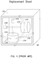
- FIG. 1 is a schematic view illustrating a conventional optical base station.
- a conventional optical base 200 uses two rotors 220A and 220B in cooperation with two light sources 210A and 210B.
- a light beam L20A provided by the light source 210A after entering the rotor 220A, rotates with the rotor 220A to scan a surrounding space.
- a light beam L20B provided by the light source 210B after entering the rotor 220B, rotates with the rotor 220B in a direction different from that of the light beam L20A to scan the surrounding space.
- the rotors 220A and 220B and the two light sources 210A and 210B are respectively located at the top, the bottom, the left, and the right of the optical base 200, ranges capable of being scanned with the light beams L20A and L20B are restricted by a housing 230 of the optical base 200. Additionally, the two rotors 220A and 220B may also cause difficulty in reducing the the volume of the optical base 200 and difficulty in cost down.
- FIG. 2 is a schematic cross-sectional view of a single rotor depicted in FIG. 1 .
- a transmission path of the light beam L20A may not coincide with a rotation axis A20 of the rotor 220A as what is expected.
- hitting points of the light beam L20A on the reflector in the rotor 220A may change with rotation of the rotor 220A, which may cause the light beam L20A reflected by the reflector to shift vertically, such that optical scanning stability may be influenced.
- the application provides an optical base station capable of resolving the problem caused by an assembly deviation.
- An optical base station including a base, a light source, a rotation plate and an optical fiber is provided by the application.
- the light source is disposed on the base for providing a light beam.
- the rotation plate is disposed on the base.
- the optical fiber is disposed on the base and has an input end and a first output end.
- the rotation plate drives the optical fiber to rotate around a rotation axis.
- the rotation axis passes through the input end.
- the light beam entering the optical fiber from the input end is transmitted in the optical fiber and output from the first output end.
- FIG. 3 is a schematic view of an optical base station according to an embodiment of the invention.
- an optical base station 100 of the present embodiment includes a base 110, a light source 120, a rotation plate 130 and an optical fiber 140.
- the light source 120 is disposed on the base 110 for providing a light beam L10.
- the rotation plate 130 is disposed on the base 110.
- the optical fiber 140 is disposed on the base 110 and has an input end 142 and a first output end 144A.
- the rotation plate 130 drives the optical fiber 140 to rotate around a rotation axis A10.
- the rotation axis A10 passes through the input end 142.
- the light beam L10 entering the optical fiber 140 from the input end 142 is transmitted in the optical fiber 140 and output from the first output end 144A.
- a position of the input end 142 of the optical fiber 140 on the rotation plate 130 is fixed, and the rotation axis A10 passes through the input end 142.
- the position of the input end 142 is equivalent to the hitting position of the light beam located on the reflector in the related art, which may ensure that the input end 142 is located on the rotation axis A10.
- a position of the first output end 144A on the rotation plate 130 is also fixed. In this way, it may ensure that the light beam L10 is output stably from a specified position.
- the optical base station 100 of the present embodiment may provide a stable optical scanning effect.
- the light source 120 and the rotation plate 130 of the present embodiment are both disposed on the same surface of the base 110.
- circuits required for driving the light source 120 and the rotation plate 130 all may be distributed on the same surface of the base 110.
- the light beam L10 output from the first output end 144A may scan the periphery of the base 110 at 360 degrees without dead space, and the interference caused by circuits at sides like what may occur in the related art can be prevented.
- the optical base station 100 may further include a cover 150 disposed on the base 110.
- the light source 120, the rotation plate 130 and the optical fiber 140 are located in an accommodation space S10 formed by the cover 150 and the base 110.
- the cover 150 may isolate the light source 120, the rotation plate 130 and the optical fiber 140 from the outside, thereby preventing disturbance and pollution by foreign particles to enhance reliability of the optical base station 100 and extend the lifespan.
- the cover 150 is transparent to the light beam L10. In other words, it does not matter whether the cover 150 is transparent when being observed by human eyes, but it matters that a material of the cover 150 allows the light beam L10 in a wave band to pass through without blocking the light beam L10 or obviously weakening the intensity of the light beam L10.
- the light source 120 is located beside the rotation plate 130 and thus, needs an adaptively designed optical system to guide the light beam L10 provided thereby to the input end 142.
- An inner top surface 152 of the cover 150 which is far away from the base 110 may have at least one reflecting portion 154, and in the present embodiment, two reflecting portions 150 are illustrated for example.
- the light beam L10 enters the input end 142 after being reflected by the two reflecting portions 154.
- the light beam L10 may also be reflected by a single reflecting portion 154 and then enters the input end 142.
- other adaptive optical systems may be also be designed to achieve the same optical effect described above.
- the optical base station 100 may further include a lens 160 disposed at the input end 142.
- the light beam L10 enters the input end 142 after passing through the lens 160.
- the lens 160 may be a condenser lens or other adaptive lenses. Certainly, the lens 160 may also be composed of a plurality of optical elements.
- the lens 160 may be fixed to the rotation plate 130 or may also be fixed to the cover 150 or the base 110.
- the optical base station 100 may further include a lens module 170 disposed at the first output end 144A.
- the light beam L10 after being output from the first output end 144A, passes through the lens module 170 and is converted to have a linear spot.
- the light beam L10 output from the first output end 144A may originally be, for example, a dotted shape.
- the spot of the light beam L10 is converted into the linear spot with the use of the lens module 170 to facilitate optical scanning.
- the spot of the light beam L10 after being output from the first output end 114A, may be made to be linear.
- the light beam L10 having the linear spot means that a shape of the light beam L10 hitting on an orthogonal plane substantially presents the linear shape.
- the lens module 170 of the present embodiment includes a condenser lens 172 and a lenticular lens sheet 174, but the application is not limited thereto.
- the divergent light beam L10 which is condensed by the condenser lens 172 enters the lenticular lens sheet 174.
- the lenticular lens sheet 174 is mainly used to change the spot shape. By adaptively designing the lenticular lens sheet 174, the light beam L10 has substantially the same intensity on each part of the linear spot thereof.
- the optical base station 100 further includes a package 180 disposed on the rotation plate 130.
- the optical fiber 140 is embedded in the package 180.
- the input end 142 and the first output end 144A are exposed from the package 180 for inputting and outputting the light beam L10.
- positions of the input end 142 and the first output end 144A of the optical fiber 140 on the rotation plate 130 may be ensured.
- the lens module 170 when the lens module 170 is disposed, the lens module 170 may also be embedded in the package 180 to maintain a relative position with respect to the the first output end 144A.
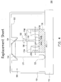
- FIG. 4 is a schematic view of an optical base station according to another embodiment of the invention.
- FIG. 5 is a schematic top view of the rotation plate depicted in FIG. 4 .
- an optical base station 300 of the present embodiment is substantially similar to the optical base station 100 illustrated in FIG. 3 , and only difference therebetween will be described below.
- An optical fiber 340 of the optical base station 300 of the present embodiment has an input end 342, a first output end 344A and a second output end 344B.
- the light beam L10 after entering the optical fiber 340 from the input end 342, is divided to respectively output a first sub light beam L10A and a second sub light beam L10B from the first output end 344A and the second output end 344B.
- the first sub light beam L10A and the second sub light beam L20 may optically scan the surroundings simultaneously while the rotation plate 130 is rotated. Accordingly, an overall height of the optical base station 300 may be reduced, so as to reduce an overall volume to meet consumers' use preference.
- the optical base station 300 may further include a first lens module 170A and a second lens module 170B respectively disposed at the first output end 344A and the second output end 344B.
- FIG. 6 is a schematic side view of the rotation plate depicted in FIG. 4 viewed from one side.
- the first sub light beam L10A after being output from the first output end 344A, passes through the first lens module 170A and is converted to have a first linear spot F12.
- FIG. 7 is a schematic side view of the rotation plate depicted in FIG. 4 viewed from the other side.
- the second sub light beam L10B after being output from the second output end 344B, passes through the second lens module 170B and is converted to have a second linear spot F14.
- the rotation axis A10 is neither parallel nor vertical to a longitudinal axis AL12 of the first linear spot F12 and a longitudinal axis AL14 of the second linear spot F14.
- the first linear spot F12 of the first sub light beam L10A may be seen, as illustrated in FIG. 6 .
- the rotation axis A10 of the rotation plate 130 is a vertical line
- the longitudinal axis AL12 of the first linear spot F12 is a straight line from upper right to lower left, and both are neither parallel nor vertical to each other.
- the second linear spot F14 of the second sub light beam L10B may be seen, as illustrated in FIG. 7 .
- the rotation axis A10 of the rotation plate 130 is a vertical line
- the longitudinal axis AL14 of the second linear spot F14 is a straight line from upper left to lower right, and both are neither parallel nor vertical to each other.
- the longitudinal axis AL12 of the first linear spot F12 is not parallel to the longitudinal axis AL14 of the second linear spot F14.
- a same light sensor located in the space receives the first sub light beam L10A and the second sub light beam L10B in turn.
- a relative position of the light sensor and the rotation plate 130 may be calculated, so as to achieve the purpose for spatially positioning the light sensor.
- the optical base station 300 of the present embodiment may two-dimensionally scan the space by using only one rotation plate 130, which may save a space occupied by the rotation plate 130, as well as save material and assembly cost in comparison with the related art.
- the first sub light beam L10A and the second sub light beam L10B are distributed in a manner with an included angle of 180 degrees, but the application is not limited thereto.
- FIG. 8 is a schematic view of an optical base station according to another embodiment of the invention viewed from the above of the rotation plate.
- an optical base station of the present embodiment and the optical base station 100 illustrated in FIG. 3 are substantially similar, but different in the design of the optical fiber, and only difference therebetween will be described below.
- An optical fiber 440 of the optical base station of the present embodiment has an input end 442, a first output end 444A, a second output end 444B, a third output end 444C and a fourth output end 444D.
- the light beam L10 after entering the optical fiber 440 from the input end 442, is divided to respectively output a first sub light beam L10A, a second sub light beam L10B, a third sub light beam L10C and a fourth sub light beam L10D from the first output end 444A, the second output end 444B, the third output end 444C and the fourth output end 444D.
- the space may be two-dimensionally scanned with the use of the first sub light beam L10A and the second sub light beam L20 and simultaneously with the use of the third sub light beam L10C and the fourth sub light beam L10D, thereby achieving a purpose of scanning at a doubled frequency by a single rotation plate.
- the first sub light beam L10A, the second sub light beam L10B, the third sub light beam L10B and the fourth sub light beam L10D are distributed in a manner with an included angle of 90 degrees, but the application is not limited thereto.
- FIG. 9 is a schematic view of an optical base station according to yet another embodiment of the invention.
- an optical base station 500 of the present embodiment is substantially similar to the optical base station 100 illustrated in FIG. 3 , and only difference therebetween will be described below.
- a rotation plate 530 of the optical base station 500 of the present embodiment has a through hole 532, and the light beam L10 enters the optical fiber 140 from the input end 142 after passing through the rotation plate 530 from the through hole 532.
- the reflecting portions 154 as illustrated in FIG. 3 is not needed for the optical base station 500 of the present embodiment.
- a lens module 570 of the present embodiment is formed by assembling the condenser lens and the lenticular lens sheet in advance.
- the modulized lens module 570 may facilitate reducing the assembly time and enhancing alignment accuracy.
- the lens module 570 may also be a single lenticular lens or replaced by another lens module.
- FIG. 10 is a schematic view of an architecture applying the optical base station depicted in FIG. 3 .
- two optical base stations 100 illustrated in FIG. 3 are used in this application architecture.
- the optical base stations 100 continuously and periodically emit light beams to a space where the user is located.
- the light sensors 56 are capable of detecting the light beams emitted from the optical base stations 100.
- instant position information regarding the head-mounted display device 52 and the control handles 54 in the space may be obtained, so as to provide a variety of VR applications to the user.
- the optical base station of the application the positions of the input end and the first output end of the optical fiber on the rotation plate are fixed, the rotation axis passes through the input end, and it can be ensured that the light beam can be output stably from a specified position.
- the optical base station of the application can provide a stable optical scanning effect.
Landscapes
- Physics & Mathematics (AREA)
- Engineering & Computer Science (AREA)
- General Physics & Mathematics (AREA)
- Optics & Photonics (AREA)
- General Engineering & Computer Science (AREA)
- Theoretical Computer Science (AREA)
- Human Computer Interaction (AREA)
- Optical Couplings Of Light Guides (AREA)
- Mechanical Optical Scanning Systems (AREA)
Abstract
Description
- This application claims the priority benefit of
U.S. provisional application serial no. 62/570,671, filed on October 11, 2017 - The application is directed to a base station and more particularly, to an optical base station.
- Virtural reality (VR) systems have become one of the major popular techniques available on the market. A user, after wearing a VR apparatus on the head, can view a three dimensional (3D) image with a display portion in front of the eyes, thereby experiencing reality and vividness. However, in order to construct a correct VR space, an optical base station for providing a spatially-positioning datum has to be equipped.
-
FIG. 1 is a schematic view illustrating a conventional optical base station. Referring toFIG. 1 , in order to two-dimensionally scan a space, a conventionaloptical base 200 uses tworotors light sources light source 210A, after entering therotor 220A, rotates with therotor 220A to scan a surrounding space. A light beam L20B provided by thelight source 210B, after entering therotor 220B, rotates with therotor 220B in a direction different from that of the light beam L20A to scan the surrounding space. However, because therotors light sources optical base 200, ranges capable of being scanned with the light beams L20A and L20B are restricted by ahousing 230 of theoptical base 200. Additionally, the tworotors optical base 200 and difficulty in cost down. -
FIG. 2 is a schematic cross-sectional view of a single rotor depicted inFIG. 1 . Referring toFIG. 2 , due to the presence of an assembly tolerance, a transmission path of the light beam L20A may not coincide with a rotation axis A20 of therotor 220A as what is expected. As such, hitting points of the light beam L20A on the reflector in therotor 220A may change with rotation of therotor 220A, which may cause the light beam L20A reflected by the reflector to shift vertically, such that optical scanning stability may be influenced. - The application provides an optical base station capable of resolving the problem caused by an assembly deviation.
- An optical base station including a base, a light source, a rotation plate and an optical fiber is provided by the application. The light source is disposed on the base for providing a light beam. The rotation plate is disposed on the base. The optical fiber is disposed on the base and has an input end and a first output end. The rotation plate drives the optical fiber to rotate around a rotation axis. The rotation axis passes through the input end. The light beam entering the optical fiber from the input end is transmitted in the optical fiber and output from the first output end.
- To sum up, in the optical base station of the application, positions where the input end and the first output end of the optical fiber are disposed on the rotation plate are fixed. Thus, the problem of an unstable optical scanning effect caused by the assembly deviation can be prevented.
- To make the above features and advantages of the invention more comprehensible, embodiments accompanied with drawings are described in detail below.
-
-
FIG. 1 is a schematic view of a conventional optical base station. -
FIG. 2 is a schematic cross-sectional view of a single rotor depicted inFIG. 1 . -
FIG. 3 is a schematic view of an optical base station according to an embodiment of the invention. -
FIG. 4 is a schematic view of an optical base station according to another embodiment of the invention. -
FIG. 5 is a schematic top view of the rotation plate depicted inFIG. 4 . -
FIG. 6 is a schematic side view of the rotation plate depicted inFIG. 4 viewed from one side. -
FIG. 7 is a schematic side view of the rotation plate depicted inFIG. 4 viewed from the other side. -
FIG. 8 is a schematic view of an optical base station according to another embodiment of the invention viewed from the above of the rotation plate. -
FIG. 9 is a schematic view of an optical base station according to yet another embodiment of the invention. -
FIG. 10 is a schematic view of an architecture applying the optical base station depicted inFIG. 3 . -
FIG. 3 is a schematic view of an optical base station according to an embodiment of the invention. Referring toFIG. 3 , anoptical base station 100 of the present embodiment includes abase 110, alight source 120, arotation plate 130 and anoptical fiber 140. Thelight source 120 is disposed on thebase 110 for providing a light beam L10. Therotation plate 130 is disposed on thebase 110. Theoptical fiber 140 is disposed on thebase 110 and has aninput end 142 and afirst output end 144A. Therotation plate 130 drives theoptical fiber 140 to rotate around a rotation axis A10. The rotation axis A10 passes through theinput end 142. The light beam L10 entering theoptical fiber 140 from theinput end 142 is transmitted in theoptical fiber 140 and output from thefirst output end 144A. - In the
optical base station 100 of the present embodiment, a position of theinput end 142 of theoptical fiber 140 on therotation plate 130 is fixed, and the rotation axis A10 passes through theinput end 142. The position of theinput end 142 is equivalent to the hitting position of the light beam located on the reflector in the related art, which may ensure that theinput end 142 is located on the rotation axis A10. Furthermore, a position of thefirst output end 144A on therotation plate 130 is also fixed. In this way, it may ensure that the light beam L10 is output stably from a specified position. Thus, the problem that the located position on the reflector changes due to the deviation between the light beam and the rotation axis of the reflector in the related art does not occur, and the finally output light beam does not shift vertically. Thereby, theoptical base station 100 of the present embodiment may provide a stable optical scanning effect. - On the other hand, because a spot shape of the light beam L10 will be re-shaped after being transmitted in the
optical fiber 140, the spot shape output from thefirst output end 144A does not change with the rotation of therotation plate 130, and a stable optical scanning effect can be obtained. - Moreover, the
light source 120 and therotation plate 130 of the present embodiment are both disposed on the same surface of thebase 110. Thus, circuits required for driving thelight source 120 and therotation plate 130 all may be distributed on the same surface of thebase 110. In this way, the light beam L10 output from thefirst output end 144A may scan the periphery of thebase 110 at 360 degrees without dead space, and the interference caused by circuits at sides like what may occur in the related art can be prevented. - In the present embodiment, the
optical base station 100 may further include acover 150 disposed on thebase 110. Thelight source 120, therotation plate 130 and theoptical fiber 140 are located in an accommodation space S10 formed by thecover 150 and thebase 110. Thecover 150 may isolate thelight source 120, therotation plate 130 and theoptical fiber 140 from the outside, thereby preventing disturbance and pollution by foreign particles to enhance reliability of theoptical base station 100 and extend the lifespan. Thecover 150 is transparent to the light beam L10. In other words, it does not matter whether thecover 150 is transparent when being observed by human eyes, but it matters that a material of thecover 150 allows the light beam L10 in a wave band to pass through without blocking the light beam L10 or obviously weakening the intensity of the light beam L10. - In the present embodiment, the
light source 120 is located beside therotation plate 130 and thus, needs an adaptively designed optical system to guide the light beam L10 provided thereby to theinput end 142. An innertop surface 152 of thecover 150 which is far away from the base 110 may have at least one reflectingportion 154, and in the present embodiment, two reflectingportions 150 are illustrated for example. The light beam L10 enters theinput end 142 after being reflected by the two reflectingportions 154. However, by adjusting an angle of the light beam L10 when being emitted and a disposition angle of the reflectingportion 154, the light beam L10 may also be reflected by asingle reflecting portion 154 and then enters theinput end 142. Alternatively, other adaptive optical systems may be also be designed to achieve the same optical effect described above. - In the present embodiment, the
optical base station 100 may further include alens 160 disposed at theinput end 142. The light beam L10 enters theinput end 142 after passing through thelens 160. Thelens 160 may be a condenser lens or other adaptive lenses. Certainly, thelens 160 may also be composed of a plurality of optical elements. Thelens 160 may be fixed to therotation plate 130 or may also be fixed to thecover 150 or thebase 110. - In the present embodiment, the
optical base station 100 may further include alens module 170 disposed at thefirst output end 144A. The light beam L10, after being output from thefirst output end 144A, passes through thelens module 170 and is converted to have a linear spot. The light beam L10 output from thefirst output end 144A may originally be, for example, a dotted shape. The spot of the light beam L10 is converted into the linear spot with the use of thelens module 170 to facilitate optical scanning. However, with an adaptive design of theoptical fiber 140, the spot of the light beam L10, after being output from the first output end 114A, may be made to be linear. The light beam L10 having the linear spot means that a shape of the light beam L10 hitting on an orthogonal plane substantially presents the linear shape. Thelens module 170 of the present embodiment includes a condenser lens 172 and alenticular lens sheet 174, but the application is not limited thereto. The divergent light beam L10 which is condensed by the condenser lens 172 enters thelenticular lens sheet 174. Thelenticular lens sheet 174 is mainly used to change the spot shape. By adaptively designing thelenticular lens sheet 174, the light beam L10 has substantially the same intensity on each part of the linear spot thereof. - In the present embodiment, the
optical base station 100 further includes apackage 180 disposed on therotation plate 130. Theoptical fiber 140 is embedded in thepackage 180. Theinput end 142 and thefirst output end 144A are exposed from thepackage 180 for inputting and outputting the light beam L10. Thus, positions of theinput end 142 and thefirst output end 144A of theoptical fiber 140 on therotation plate 130 may be ensured. In addition, when thelens module 170 is disposed, thelens module 170 may also be embedded in thepackage 180 to maintain a relative position with respect to the thefirst output end 144A. -
FIG. 4 is a schematic view of an optical base station according to another embodiment of the invention.FIG. 5 is a schematic top view of the rotation plate depicted inFIG. 4 . Referring toFIG. 4 andFIG 5 , anoptical base station 300 of the present embodiment is substantially similar to theoptical base station 100 illustrated inFIG. 3 , and only difference therebetween will be described below. An optical fiber 340 of theoptical base station 300 of the present embodiment has aninput end 342, afirst output end 344A and asecond output end 344B. The light beam L10, after entering the optical fiber 340 from theinput end 342, is divided to respectively output a first sub light beam L10A and a second sub light beam L10B from thefirst output end 344A and thesecond output end 344B. Thus, the first sub light beam L10A and the second sub light beam L20 may optically scan the surroundings simultaneously while therotation plate 130 is rotated. Accordingly, an overall height of theoptical base station 300 may be reduced, so as to reduce an overall volume to meet consumers' use preference. - In the present embodiment, the
optical base station 300 may further include afirst lens module 170A and asecond lens module 170B respectively disposed at thefirst output end 344A and thesecond output end 344B.FIG. 6 is a schematic side view of the rotation plate depicted inFIG. 4 viewed from one side. Referring toFIG. 5 andFIG. 6 , the first sub light beam L10A, after being output from thefirst output end 344A, passes through thefirst lens module 170A and is converted to have a first linear spot F12.FIG. 7 is a schematic side view of the rotation plate depicted inFIG. 4 viewed from the other side. Referring toFIG. 5 andFIG. 7 , the second sub light beam L10B, after being output from thesecond output end 344B, passes through thesecond lens module 170B and is converted to have a second linear spot F14. - The rotation axis A10 is neither parallel nor vertical to a longitudinal axis AL12 of the first linear spot F12 and a longitudinal axis AL14 of the second linear spot F14. Specifically, by viewing the
rotation plate 130 along a transmission direction of the first sub light beam L10A, the first linear spot F12 of the first sub light beam L10A may be seen, as illustrated inFIG. 6 . InFIG. 6 , the rotation axis A10 of therotation plate 130 is a vertical line, the longitudinal axis AL12 of the first linear spot F12 is a straight line from upper right to lower left, and both are neither parallel nor vertical to each other. On the other hand, by viewing therotation plate 130 along a transmission direction of the second sub light beam L10B, the second linear spot F14 of the second sub light beam L10B may be seen, as illustrated inFIG. 7 . InFIG. 7 , the rotation axis A10 of therotation plate 130 is a vertical line, the longitudinal axis AL14 of the second linear spot F14 is a straight line from upper left to lower right, and both are neither parallel nor vertical to each other. Additionally, according to bothFIG. 6 and FIG. 7 , the longitudinal axis AL12 of the first linear spot F12 is not parallel to the longitudinal axis AL14 of the second linear spot F14. - In view of the conditions mentioned above, when the
rotation plate 130 rotates around the rotation axis A10 to scan the surrounding space simultaneously with the first sub light beam L10A and the second sub light beam L10B, a same light sensor (which is not shown) located in the space receives the first sub light beam L10A and the second sub light beam L10B in turn. According to a time difference between reception times of the first sub light beam L10A and the second sub light beam L10B and incident angles of the first sub light beam L10A and the second sub light beam L10B, a relative position of the light sensor and therotation plate 130 may be calculated, so as to achieve the purpose for spatially positioning the light sensor. In this way, theoptical base station 300 of the present embodiment may two-dimensionally scan the space by using only onerotation plate 130, which may save a space occupied by therotation plate 130, as well as save material and assembly cost in comparison with the related art. In this case, the first sub light beam L10A and the second sub light beam L10B are distributed in a manner with an included angle of 180 degrees, but the application is not limited thereto. -
FIG. 8 is a schematic view of an optical base station according to another embodiment of the invention viewed from the above of the rotation plate. Referring toFIG. 8 , an optical base station of the present embodiment and theoptical base station 100 illustrated inFIG. 3 are substantially similar, but different in the design of the optical fiber, and only difference therebetween will be described below. Anoptical fiber 440 of the optical base station of the present embodiment has aninput end 442, afirst output end 444A, asecond output end 444B, athird output end 444C and afourth output end 444D. The light beam L10, after entering theoptical fiber 440 from theinput end 442, is divided to respectively output a first sub light beam L10A, a second sub light beam L10B, a third sub light beam L10C and a fourth sub light beam L10D from thefirst output end 444A, thesecond output end 444B, thethird output end 444C and thefourth output end 444D. Being similar to the previous embodiment, the space may be two-dimensionally scanned with the use of the first sub light beam L10A and the second sub light beam L20 and simultaneously with the use of the third sub light beam L10C and the fourth sub light beam L10D, thereby achieving a purpose of scanning at a doubled frequency by a single rotation plate. In this case, the first sub light beam L10A, the second sub light beam L10B, the third sub light beam L10B and the fourth sub light beam L10D are distributed in a manner with an included angle of 90 degrees, but the application is not limited thereto. -
FIG. 9 is a schematic view of an optical base station according to yet another embodiment of the invention. Referring toFIG. 9 , anoptical base station 500 of the present embodiment is substantially similar to theoptical base station 100 illustrated inFIG. 3 , and only difference therebetween will be described below. Arotation plate 530 of theoptical base station 500 of the present embodiment has a throughhole 532, and the light beam L10 enters theoptical fiber 140 from theinput end 142 after passing through therotation plate 530 from the throughhole 532. Thus, the reflectingportions 154 as illustrated inFIG. 3 is not needed for theoptical base station 500 of the present embodiment. In addition, alens module 570 of the present embodiment is formed by assembling the condenser lens and the lenticular lens sheet in advance. By comparing the condenser lens and the lenticular lens sheet being separately assembled to theoptical base station 500, themodulized lens module 570 may facilitate reducing the assembly time and enhancing alignment accuracy. In addition, thelens module 570 may also be a single lenticular lens or replaced by another lens module. -
FIG. 10 is a schematic view of an architecture applying the optical base station depicted inFIG. 3 . Referring toFIG. 10 , twooptical base stations 100 illustrated inFIG. 3 are used in this application architecture. When a user wears a head-mounteddisplay device 52 and holds acontrol handle 54 with each hand, theoptical base stations 100 continuously and periodically emit light beams to a space where the user is located. There are a plurality of light sensors disposed on the head-mounteddisplay device 52 and the control handles 54, butFIG. 10 only illustrates a light sensor disposed on the head-mounteddisplay device 52. Thelight sensors 56 are capable of detecting the light beams emitted from theoptical base stations 100. By analyzing time information related to the light beams detected by thelight sensors 56 and geometric positions of thelight sensors 56 on the head-mounteddisplay device 52 and the control handles 54, instant position information regarding the head-mounteddisplay device 52 and the control handles 54 in the space may be obtained, so as to provide a variety of VR applications to the user. - Based on the above, in the optical base station of the application, the positions of the input end and the first output end of the optical fiber on the rotation plate are fixed, the rotation axis passes through the input end, and it can be ensured that the light beam can be output stably from a specified position. Thus, the optical base station of the application can provide a stable optical scanning effect.
- Although the invention has been disclosed by the above embodiments, they are not intended to limit the invention. It will be apparent to one of ordinary skill in the art that modifications and variations to the invention may be made without departing from the spirit and scope of the invention. Therefore, the scope of the invention will be defined by the appended claims.
Claims (11)
- An optical base station, comprising:a base;a light source, disposed on the base for providing a light beam;a rotation plate, disposed on the base; andan optical fiber, disposed on the base and having an input end and a first output end, wherein the rotation plate drives the optical fiber to rotate around a rotation axis, the rotation axis passes through the input end, and the light beam entering the optical fiber from the input end is transmitted in the optical fiber and output from the first output end.
- The optical base station according to claim 1, further comprising a cover, disposed on the base, wherein the light source, the rotation plate and the optical fiber are located in an accommodation space formed by the cover and the base, and the cover is transparent to the light beam.
- The optical base station according to claim 2, wherein an inner top surface of the cover which is far away from the base has at least one reflecting portion, and the light beam enters the input end after being reflected by the reflecting portion.
- The optical base station according to claim 1, further comprising a lens disposed at the input end, wherein the light beam enters the input end after passing through the lens.
- The optical base station according to claim 1, further comprising a lens module disposed at the first input end, wherein the light beam, after being output from the first output end, passes through the lens module and is converted to have an linear spot.
- The optical base station according to claim 1, wherein the lens module is a single lenticular lens, or the lens module comprises a condenser lens and a lenticular lens sheet.
- The optical base station according to claim 1, wherein the optical fiber further has a second output end, the light beam, after entering the optical fiber from the input end, is divided to respectively output a first sub light beam and a second sub light beam from the first output end and the second output end.
- The optical base station according to claim 7, further comprising a first lens module and a second lens module respectively disposed at the first output end and the second output end, wherein the first sub light beam, after being output from the first output end, passes through the first lens module and is converted to have a first linear spot, the second sub light beam, after being output from the second output end, passes through the second lens module and is converted to have a second linear spot, the rotation axis is neither parallel nor vertical to a longitudinal axis of the first linear spot and a longitudinal axis of the second linear spot, and the longitudinal axis of the first linear spot is not parallel to the longitudinal axis of the second linear spot.
- The optical base station according to claim 1, wherein the optical fiber further has a second output end, a third output end and a fourth output end, and the light beam, after entering the optical fiber from the input end, is divided to respectively output a first sub light beam, a second sub light beam, a third sub light beam and a fourth sub light beam from the first output end, the second output end, the third output end and the fourth output end.
- The optical base station according to claim 1, further comprising a package disposed on the rotation plate, wherein the optical fiber is embedded in the package, and the input end and the first output end are exposed from the package.
- The optical base station according to claim 1, wherein the rotation plate has a through hole, and the light beam enters the optical fiber from the input end after passing through the rotation plate from the through hole.
Applications Claiming Priority (2)
| Application Number | Priority Date | Filing Date | Title |
|---|---|---|---|
| US201762570671P | 2017-10-11 | 2017-10-11 | |
| US15/920,456 US10146047B1 (en) | 2017-10-11 | 2018-03-14 | Optical base station |
Publications (2)
| Publication Number | Publication Date |
|---|---|
| EP3470907A1 true EP3470907A1 (en) | 2019-04-17 |
| EP3470907B1 EP3470907B1 (en) | 2022-07-20 |
Family
ID=64451922
Family Applications (1)
| Application Number | Title | Priority Date | Filing Date |
|---|---|---|---|
| EP18178886.0A Active EP3470907B1 (en) | 2017-10-11 | 2018-06-20 | Virtual reality system including optical base stations |
Country Status (4)
| Country | Link |
|---|---|
| US (1) | US10146047B1 (en) |
| EP (1) | EP3470907B1 (en) |
| CN (1) | CN109656017A (en) |
| TW (1) | TWI651628B (en) |
Cited By (1)
| Publication number | Priority date | Publication date | Assignee | Title |
|---|---|---|---|---|
| WO2021123500A1 (en) * | 2019-12-19 | 2021-06-24 | Teknologian Tutkimuskeskus Vtt Oy | A lens for a microelectromechanical system mirror |
Families Citing this family (2)
| Publication number | Priority date | Publication date | Assignee | Title |
|---|---|---|---|---|
| CN114488539B (en) * | 2019-04-30 | 2024-10-29 | 成都理想境界科技有限公司 | A scanning display module and near-eye display device |
| GB201906420D0 (en) * | 2019-05-07 | 2019-06-19 | Farley Adam | Virtual augmented and mixed reality systems with physical feedback |
Citations (5)
| Publication number | Priority date | Publication date | Assignee | Title |
|---|---|---|---|---|
| EP0067363A1 (en) * | 1981-06-17 | 1982-12-22 | Mita Industrial Co. Ltd. | Light deflector |
| US6057915A (en) * | 1996-06-21 | 2000-05-02 | Thermotrex Corporation | Projectile tracking system |
| DE19928957A1 (en) * | 1999-05-22 | 2000-11-23 | Volkswagen Ag | Receiving device for a laser scanner |
| EP2645125A1 (en) * | 2012-03-27 | 2013-10-02 | Sick AG | Optoelectronic sensor and method for detecting objects in a surveillance area |
| US20160131761A1 (en) * | 2014-11-10 | 2016-05-12 | Valve Corporation | Positional tracking systems and methods |
Family Cites Families (9)
| Publication number | Priority date | Publication date | Assignee | Title |
|---|---|---|---|---|
| DE19927501A1 (en) * | 1999-05-22 | 2000-11-23 | Volkswagen Ag | Transmitter for laser scanner has laser light source for generating laser light beam(s) that is radiated in rotary manner and that has vertically expanding beam profile |
| DE10058761B4 (en) * | 2000-11-27 | 2008-01-31 | Maschinenfabrik Wifag | imaging device |
| CN101213482A (en) * | 2005-05-09 | 2008-07-02 | Seo精密公司 | Omnidirectional lamp |
| WO2010141120A2 (en) * | 2009-02-20 | 2010-12-09 | Digital Signal Corporation | System and method for generating three dimensional images using lidar and video measurements |
| CN104390952A (en) | 2014-12-15 | 2015-03-04 | 中国科学院重庆绿色智能技术研究院 | Linear focus Raman scattering probe |
| US10168429B2 (en) | 2015-04-07 | 2019-01-01 | GM Global Technology Operations LLC | Compact LIDAR system |
| US10761196B2 (en) | 2016-02-18 | 2020-09-01 | Aeye, Inc. | Adaptive ladar receiving method |
| US9921408B2 (en) * | 2016-02-26 | 2018-03-20 | Qualcomm Incorporated | Collimating light emitted by a fiber via an array of lenslets on a curved surface |
| CN206541019U (en) * | 2017-03-03 | 2017-10-03 | 北京国承万通信息科技有限公司 | Position optical signal launch equipment, optical positioning system and virtual reality system |
-
2018
- 2018-03-14 CN CN201810208235.8A patent/CN109656017A/en active Pending
- 2018-03-14 US US15/920,456 patent/US10146047B1/en active Active
- 2018-03-14 TW TW107108610A patent/TWI651628B/en active
- 2018-06-20 EP EP18178886.0A patent/EP3470907B1/en active Active
Patent Citations (5)
| Publication number | Priority date | Publication date | Assignee | Title |
|---|---|---|---|---|
| EP0067363A1 (en) * | 1981-06-17 | 1982-12-22 | Mita Industrial Co. Ltd. | Light deflector |
| US6057915A (en) * | 1996-06-21 | 2000-05-02 | Thermotrex Corporation | Projectile tracking system |
| DE19928957A1 (en) * | 1999-05-22 | 2000-11-23 | Volkswagen Ag | Receiving device for a laser scanner |
| EP2645125A1 (en) * | 2012-03-27 | 2013-10-02 | Sick AG | Optoelectronic sensor and method for detecting objects in a surveillance area |
| US20160131761A1 (en) * | 2014-11-10 | 2016-05-12 | Valve Corporation | Positional tracking systems and methods |
Cited By (2)
| Publication number | Priority date | Publication date | Assignee | Title |
|---|---|---|---|---|
| WO2021123500A1 (en) * | 2019-12-19 | 2021-06-24 | Teknologian Tutkimuskeskus Vtt Oy | A lens for a microelectromechanical system mirror |
| US12378108B2 (en) | 2019-12-19 | 2025-08-05 | Teknologian Tutkimuskeskus Vtt Oy | Lens for a microelectromechanical system mirror |
Also Published As
| Publication number | Publication date |
|---|---|
| US10146047B1 (en) | 2018-12-04 |
| CN109656017A (en) | 2019-04-19 |
| TWI651628B (en) | 2019-02-21 |
| EP3470907B1 (en) | 2022-07-20 |
| TW201915669A (en) | 2019-04-16 |
Similar Documents
| Publication | Publication Date | Title |
|---|---|---|
| EP3447561B1 (en) | Head-up display device | |
| US8045248B2 (en) | Optical scanning device and image forming apparatus | |
| US9594249B2 (en) | Image display device | |
| KR102519000B1 (en) | image display device | |
| JPH09167198A (en) | Reader | |
| CN110376742A (en) | Near-eye display and near-eye display system | |
| KR20170063647A (en) | Head-up display device | |
| US10146047B1 (en) | Optical base station | |
| US9651773B2 (en) | Optical device, image display device, and method of manufacturing optical device | |
| US20140139553A1 (en) | Virtual image display apparatus | |
| KR102961743B1 (en) | Lens holder, optical module including the same and eye glass type augmentted reality providing device | |
| CN106353885A (en) | Image display device | |
| US20240107143A1 (en) | Display device and head mounted display device | |
| CN113767319B (en) | Image display device and display device | |
| US20110128592A1 (en) | Erecting equal-magnification lens array plate, optical scanning unit, and image reading device | |
| US6768101B1 (en) | High resolution optical encoder with an angular collimated light beam | |
| US9213132B2 (en) | Directional backlight unit | |
| US10830412B2 (en) | Light emitting device and image display system | |
| US20050093966A1 (en) | Multibeam light source unit, laser scanning apparatus having the same and method for assembling the laser scanning apparatus | |
| US10670849B2 (en) | Observation device | |
| US11846814B2 (en) | Hologram display device | |
| JP4590916B2 (en) | Image display device | |
| JP4928859B2 (en) | Optical data input method and apparatus, and spectroscopic lens module of the apparatus | |
| JP4635600B2 (en) | Optical scanning device | |
| US20220328540A1 (en) | Image reading device |
Legal Events
| Date | Code | Title | Description |
|---|---|---|---|
| STAA | Information on the status of an ep patent application or granted ep patent |
Free format text: STATUS: EXAMINATION IS IN PROGRESS |
|
| PUAI | Public reference made under article 153(3) epc to a published international application that has entered the european phase |
Free format text: ORIGINAL CODE: 0009012 |
|
| 17P | Request for examination filed |
Effective date: 20180620 |
|
| AK | Designated contracting states |
Kind code of ref document: A1 Designated state(s): AL AT BE BG CH CY CZ DE DK EE ES FI FR GB GR HR HU IE IS IT LI LT LU LV MC MK MT NL NO PL PT RO RS SE SI SK SM TR |
|
| AX | Request for extension of the european patent |
Extension state: BA ME |
|
| RBV | Designated contracting states (corrected) |
Designated state(s): AL AT BE BG CH CY CZ DE DK EE ES FI FR GB GR HR HU IE IS IT LI LT LU LV MC MK MT NL NO PL PT RO RS SE SI SK SM TR |
|
| GRAP | Despatch of communication of intention to grant a patent |
Free format text: ORIGINAL CODE: EPIDOSNIGR1 |
|
| STAA | Information on the status of an ep patent application or granted ep patent |
Free format text: STATUS: GRANT OF PATENT IS INTENDED |
|
| INTG | Intention to grant announced |
Effective date: 20220210 |
|
| GRAS | Grant fee paid |
Free format text: ORIGINAL CODE: EPIDOSNIGR3 |
|
| GRAA | (expected) grant |
Free format text: ORIGINAL CODE: 0009210 |
|
| STAA | Information on the status of an ep patent application or granted ep patent |
Free format text: STATUS: THE PATENT HAS BEEN GRANTED |
|
| AK | Designated contracting states |
Kind code of ref document: B1 Designated state(s): AL AT BE BG CH CY CZ DE DK EE ES FI FR GB GR HR HU IE IS IT LI LT LU LV MC MK MT NL NO PL PT RO RS SE SI SK SM TR |
|
| REG | Reference to a national code |
Ref country code: CH Ref legal event code: EP |
|
| REG | Reference to a national code |
Ref country code: DE Ref legal event code: R096 Ref document number: 602018038052 Country of ref document: DE |
|
| REG | Reference to a national code |
Ref country code: AT Ref legal event code: REF Ref document number: 1505898 Country of ref document: AT Kind code of ref document: T Effective date: 20220815 |
|
| REG | Reference to a national code |
Ref country code: IE Ref legal event code: FG4D |
|
| REG | Reference to a national code |
Ref country code: LT Ref legal event code: MG9D |
|
| REG | Reference to a national code |
Ref country code: NL Ref legal event code: MP Effective date: 20220720 |
|
| PG25 | Lapsed in a contracting state [announced via postgrant information from national office to epo] |
Ref country code: SE Free format text: LAPSE BECAUSE OF FAILURE TO SUBMIT A TRANSLATION OF THE DESCRIPTION OR TO PAY THE FEE WITHIN THE PRESCRIBED TIME-LIMIT Effective date: 20220720 Ref country code: RS Free format text: LAPSE BECAUSE OF FAILURE TO SUBMIT A TRANSLATION OF THE DESCRIPTION OR TO PAY THE FEE WITHIN THE PRESCRIBED TIME-LIMIT Effective date: 20220720 Ref country code: PT Free format text: LAPSE BECAUSE OF FAILURE TO SUBMIT A TRANSLATION OF THE DESCRIPTION OR TO PAY THE FEE WITHIN THE PRESCRIBED TIME-LIMIT Effective date: 20221121 Ref country code: NO Free format text: LAPSE BECAUSE OF FAILURE TO SUBMIT A TRANSLATION OF THE DESCRIPTION OR TO PAY THE FEE WITHIN THE PRESCRIBED TIME-LIMIT Effective date: 20221020 Ref country code: NL Free format text: LAPSE BECAUSE OF FAILURE TO SUBMIT A TRANSLATION OF THE DESCRIPTION OR TO PAY THE FEE WITHIN THE PRESCRIBED TIME-LIMIT Effective date: 20220720 Ref country code: LV Free format text: LAPSE BECAUSE OF FAILURE TO SUBMIT A TRANSLATION OF THE DESCRIPTION OR TO PAY THE FEE WITHIN THE PRESCRIBED TIME-LIMIT Effective date: 20220720 Ref country code: LT Free format text: LAPSE BECAUSE OF FAILURE TO SUBMIT A TRANSLATION OF THE DESCRIPTION OR TO PAY THE FEE WITHIN THE PRESCRIBED TIME-LIMIT Effective date: 20220720 Ref country code: FI Free format text: LAPSE BECAUSE OF FAILURE TO SUBMIT A TRANSLATION OF THE DESCRIPTION OR TO PAY THE FEE WITHIN THE PRESCRIBED TIME-LIMIT Effective date: 20220720 Ref country code: ES Free format text: LAPSE BECAUSE OF FAILURE TO SUBMIT A TRANSLATION OF THE DESCRIPTION OR TO PAY THE FEE WITHIN THE PRESCRIBED TIME-LIMIT Effective date: 20220720 |
|
| REG | Reference to a national code |
Ref country code: AT Ref legal event code: MK05 Ref document number: 1505898 Country of ref document: AT Kind code of ref document: T Effective date: 20220720 |
|
| PG25 | Lapsed in a contracting state [announced via postgrant information from national office to epo] |
Ref country code: PL Free format text: LAPSE BECAUSE OF FAILURE TO SUBMIT A TRANSLATION OF THE DESCRIPTION OR TO PAY THE FEE WITHIN THE PRESCRIBED TIME-LIMIT Effective date: 20220720 Ref country code: IS Free format text: LAPSE BECAUSE OF FAILURE TO SUBMIT A TRANSLATION OF THE DESCRIPTION OR TO PAY THE FEE WITHIN THE PRESCRIBED TIME-LIMIT Effective date: 20221120 Ref country code: HR Free format text: LAPSE BECAUSE OF FAILURE TO SUBMIT A TRANSLATION OF THE DESCRIPTION OR TO PAY THE FEE WITHIN THE PRESCRIBED TIME-LIMIT Effective date: 20220720 Ref country code: GR Free format text: LAPSE BECAUSE OF FAILURE TO SUBMIT A TRANSLATION OF THE DESCRIPTION OR TO PAY THE FEE WITHIN THE PRESCRIBED TIME-LIMIT Effective date: 20221021 |
|
| REG | Reference to a national code |
Ref country code: DE Ref legal event code: R097 Ref document number: 602018038052 Country of ref document: DE |
|
| PG25 | Lapsed in a contracting state [announced via postgrant information from national office to epo] |
Ref country code: SM Free format text: LAPSE BECAUSE OF FAILURE TO SUBMIT A TRANSLATION OF THE DESCRIPTION OR TO PAY THE FEE WITHIN THE PRESCRIBED TIME-LIMIT Effective date: 20220720 Ref country code: RO Free format text: LAPSE BECAUSE OF FAILURE TO SUBMIT A TRANSLATION OF THE DESCRIPTION OR TO PAY THE FEE WITHIN THE PRESCRIBED TIME-LIMIT Effective date: 20220720 Ref country code: DK Free format text: LAPSE BECAUSE OF FAILURE TO SUBMIT A TRANSLATION OF THE DESCRIPTION OR TO PAY THE FEE WITHIN THE PRESCRIBED TIME-LIMIT Effective date: 20220720 Ref country code: CZ Free format text: LAPSE BECAUSE OF FAILURE TO SUBMIT A TRANSLATION OF THE DESCRIPTION OR TO PAY THE FEE WITHIN THE PRESCRIBED TIME-LIMIT Effective date: 20220720 Ref country code: AT Free format text: LAPSE BECAUSE OF FAILURE TO SUBMIT A TRANSLATION OF THE DESCRIPTION OR TO PAY THE FEE WITHIN THE PRESCRIBED TIME-LIMIT Effective date: 20220720 |
|
| PLBE | No opposition filed within time limit |
Free format text: ORIGINAL CODE: 0009261 |
|
| STAA | Information on the status of an ep patent application or granted ep patent |
Free format text: STATUS: NO OPPOSITION FILED WITHIN TIME LIMIT |
|
| PG25 | Lapsed in a contracting state [announced via postgrant information from national office to epo] |
Ref country code: SK Free format text: LAPSE BECAUSE OF FAILURE TO SUBMIT A TRANSLATION OF THE DESCRIPTION OR TO PAY THE FEE WITHIN THE PRESCRIBED TIME-LIMIT Effective date: 20220720 Ref country code: EE Free format text: LAPSE BECAUSE OF FAILURE TO SUBMIT A TRANSLATION OF THE DESCRIPTION OR TO PAY THE FEE WITHIN THE PRESCRIBED TIME-LIMIT Effective date: 20220720 |
|
| 26N | No opposition filed |
Effective date: 20230421 |
|
| PG25 | Lapsed in a contracting state [announced via postgrant information from national office to epo] |
Ref country code: AL Free format text: LAPSE BECAUSE OF FAILURE TO SUBMIT A TRANSLATION OF THE DESCRIPTION OR TO PAY THE FEE WITHIN THE PRESCRIBED TIME-LIMIT Effective date: 20220720 |
|
| P01 | Opt-out of the competence of the unified patent court (upc) registered |
Effective date: 20230602 |
|
| PG25 | Lapsed in a contracting state [announced via postgrant information from national office to epo] |
Ref country code: SI Free format text: LAPSE BECAUSE OF FAILURE TO SUBMIT A TRANSLATION OF THE DESCRIPTION OR TO PAY THE FEE WITHIN THE PRESCRIBED TIME-LIMIT Effective date: 20220720 |
|
| PG25 | Lapsed in a contracting state [announced via postgrant information from national office to epo] |
Ref country code: MC Free format text: LAPSE BECAUSE OF FAILURE TO SUBMIT A TRANSLATION OF THE DESCRIPTION OR TO PAY THE FEE WITHIN THE PRESCRIBED TIME-LIMIT Effective date: 20220720 |
|
| PG25 | Lapsed in a contracting state [announced via postgrant information from national office to epo] |
Ref country code: MC Free format text: LAPSE BECAUSE OF FAILURE TO SUBMIT A TRANSLATION OF THE DESCRIPTION OR TO PAY THE FEE WITHIN THE PRESCRIBED TIME-LIMIT Effective date: 20220720 |
|
| REG | Reference to a national code |
Ref country code: CH Ref legal event code: PL |
|
| REG | Reference to a national code |
Ref country code: BE Ref legal event code: MM Effective date: 20230630 |
|
| PG25 | Lapsed in a contracting state [announced via postgrant information from national office to epo] |
Ref country code: LU Free format text: LAPSE BECAUSE OF NON-PAYMENT OF DUE FEES Effective date: 20230620 |
|
| REG | Reference to a national code |
Ref country code: IE Ref legal event code: MM4A |
|
| PG25 | Lapsed in a contracting state [announced via postgrant information from national office to epo] |
Ref country code: LU Free format text: LAPSE BECAUSE OF NON-PAYMENT OF DUE FEES Effective date: 20230620 |
|
| PG25 | Lapsed in a contracting state [announced via postgrant information from national office to epo] |
Ref country code: IE Free format text: LAPSE BECAUSE OF NON-PAYMENT OF DUE FEES Effective date: 20230620 |
|
| PG25 | Lapsed in a contracting state [announced via postgrant information from national office to epo] |
Ref country code: IE Free format text: LAPSE BECAUSE OF NON-PAYMENT OF DUE FEES Effective date: 20230620 Ref country code: CH Free format text: LAPSE BECAUSE OF NON-PAYMENT OF DUE FEES Effective date: 20230630 |
|
| PG25 | Lapsed in a contracting state [announced via postgrant information from national office to epo] |
Ref country code: IT Free format text: LAPSE BECAUSE OF FAILURE TO SUBMIT A TRANSLATION OF THE DESCRIPTION OR TO PAY THE FEE WITHIN THE PRESCRIBED TIME-LIMIT Effective date: 20220720 Ref country code: BE Free format text: LAPSE BECAUSE OF NON-PAYMENT OF DUE FEES Effective date: 20230630 |
|
| PG25 | Lapsed in a contracting state [announced via postgrant information from national office to epo] |
Ref country code: BG Free format text: LAPSE BECAUSE OF FAILURE TO SUBMIT A TRANSLATION OF THE DESCRIPTION OR TO PAY THE FEE WITHIN THE PRESCRIBED TIME-LIMIT Effective date: 20220720 |
|
| PG25 | Lapsed in a contracting state [announced via postgrant information from national office to epo] |
Ref country code: BG Free format text: LAPSE BECAUSE OF FAILURE TO SUBMIT A TRANSLATION OF THE DESCRIPTION OR TO PAY THE FEE WITHIN THE PRESCRIBED TIME-LIMIT Effective date: 20220720 |
|
| PGFP | Annual fee paid to national office [announced via postgrant information from national office to epo] |
Ref country code: DE Payment date: 20250402 Year of fee payment: 8 |
|
| PGFP | Annual fee paid to national office [announced via postgrant information from national office to epo] |
Ref country code: FR Payment date: 20250409 Year of fee payment: 8 |
|
| PG25 | Lapsed in a contracting state [announced via postgrant information from national office to epo] |
Ref country code: CY Free format text: LAPSE BECAUSE OF FAILURE TO SUBMIT A TRANSLATION OF THE DESCRIPTION OR TO PAY THE FEE WITHIN THE PRESCRIBED TIME-LIMIT; INVALID AB INITIO Effective date: 20180620 |
|
| PG25 | Lapsed in a contracting state [announced via postgrant information from national office to epo] |
Ref country code: HU Free format text: LAPSE BECAUSE OF FAILURE TO SUBMIT A TRANSLATION OF THE DESCRIPTION OR TO PAY THE FEE WITHIN THE PRESCRIBED TIME-LIMIT; INVALID AB INITIO Effective date: 20180620 |
|
| PG25 | Lapsed in a contracting state [announced via postgrant information from national office to epo] |
Ref country code: TR Free format text: LAPSE BECAUSE OF FAILURE TO SUBMIT A TRANSLATION OF THE DESCRIPTION OR TO PAY THE FEE WITHIN THE PRESCRIBED TIME-LIMIT Effective date: 20220720 |
|
| PGFP | Annual fee paid to national office [announced via postgrant information from national office to epo] |
Ref country code: GB Payment date: 20260408 Year of fee payment: 9 |