EP3470898A1 - Optical connector - Google Patents
Optical connector Download PDFInfo
- Publication number
- EP3470898A1 EP3470898A1 EP17824006.5A EP17824006A EP3470898A1 EP 3470898 A1 EP3470898 A1 EP 3470898A1 EP 17824006 A EP17824006 A EP 17824006A EP 3470898 A1 EP3470898 A1 EP 3470898A1
- Authority
- EP
- European Patent Office
- Prior art keywords
- core
- ferrule
- blocks
- accommodating portion
- accommodated
- Prior art date
- Legal status (The legal status is an assumption and is not a legal conclusion. Google has not performed a legal analysis and makes no representation as to the accuracy of the status listed.)
- Granted
Links
Images





Classifications
-
- G—PHYSICS
- G02—OPTICS
- G02B—OPTICAL ELEMENTS, SYSTEMS OR APPARATUS
- G02B6/00—Light guides; Structural details of arrangements comprising light guides and other optical elements, e.g. couplings
- G02B6/02—Optical fibres with cladding with or without a coating
- G02B6/02042—Multicore optical fibres
-
- G—PHYSICS
- G02—OPTICS
- G02B—OPTICAL ELEMENTS, SYSTEMS OR APPARATUS
- G02B6/00—Light guides; Structural details of arrangements comprising light guides and other optical elements, e.g. couplings
- G02B6/02—Optical fibres with cladding with or without a coating
-
- G—PHYSICS
- G02—OPTICS
- G02B—OPTICAL ELEMENTS, SYSTEMS OR APPARATUS
- G02B6/00—Light guides; Structural details of arrangements comprising light guides and other optical elements, e.g. couplings
- G02B6/24—Coupling light guides
- G02B6/36—Mechanical coupling means
-
- G—PHYSICS
- G02—OPTICS
- G02B—OPTICAL ELEMENTS, SYSTEMS OR APPARATUS
- G02B6/00—Light guides; Structural details of arrangements comprising light guides and other optical elements, e.g. couplings
- G02B6/24—Coupling light guides
- G02B6/36—Mechanical coupling means
- G02B6/38—Mechanical coupling means having fibre to fibre mating means
- G02B6/3807—Dismountable connectors, i.e. comprising plugs
- G02B6/3873—Connectors using guide surfaces for aligning ferrule ends, e.g. tubes, sleeves, V-grooves, rods, pins, balls
- G02B6/3885—Multicore or multichannel optical connectors, i.e. one single ferrule containing more than one fibre, e.g. ribbon type
-
- G—PHYSICS
- G02—OPTICS
- G02B—OPTICAL ELEMENTS, SYSTEMS OR APPARATUS
- G02B6/00—Light guides; Structural details of arrangements comprising light guides and other optical elements, e.g. couplings
- G02B6/24—Coupling light guides
- G02B6/36—Mechanical coupling means
- G02B6/3628—Mechanical coupling means for mounting fibres to supporting carriers
- G02B6/3664—2D cross sectional arrangements of the fibres
- G02B6/3672—2D cross sectional arrangements of the fibres with fibres arranged in a regular matrix array
-
- G—PHYSICS
- G02—OPTICS
- G02B—OPTICAL ELEMENTS, SYSTEMS OR APPARATUS
- G02B6/00—Light guides; Structural details of arrangements comprising light guides and other optical elements, e.g. couplings
- G02B6/24—Coupling light guides
- G02B6/36—Mechanical coupling means
- G02B6/3628—Mechanical coupling means for mounting fibres to supporting carriers
- G02B6/3664—2D cross sectional arrangements of the fibres
- G02B6/3676—Stacked arrangement
-
- G—PHYSICS
- G02—OPTICS
- G02B—OPTICAL ELEMENTS, SYSTEMS OR APPARATUS
- G02B6/00—Light guides; Structural details of arrangements comprising light guides and other optical elements, e.g. couplings
- G02B6/24—Coupling light guides
- G02B6/36—Mechanical coupling means
- G02B6/38—Mechanical coupling means having fibre to fibre mating means
- G02B6/3807—Dismountable connectors, i.e. comprising plugs
- G02B6/381—Dismountable connectors, i.e. comprising plugs of the ferrule type, e.g. fibre ends embedded in ferrules, connecting a pair of fibres
- G02B6/3826—Dismountable connectors, i.e. comprising plugs of the ferrule type, e.g. fibre ends embedded in ferrules, connecting a pair of fibres characterised by form or shape
- G02B6/3831—Dismountable connectors, i.e. comprising plugs of the ferrule type, e.g. fibre ends embedded in ferrules, connecting a pair of fibres characterised by form or shape comprising a keying element on the plug or adapter, e.g. to forbid wrong connection
-
- G—PHYSICS
- G02—OPTICS
- G02B—OPTICAL ELEMENTS, SYSTEMS OR APPARATUS
- G02B6/00—Light guides; Structural details of arrangements comprising light guides and other optical elements, e.g. couplings
- G02B6/24—Coupling light guides
- G02B6/36—Mechanical coupling means
- G02B6/38—Mechanical coupling means having fibre to fibre mating means
- G02B6/3807—Dismountable connectors, i.e. comprising plugs
- G02B6/3833—Details of mounting fibres in ferrules; Assembly methods; Manufacture
- G02B6/3834—Means for centering or aligning the light guide within the ferrule
-
- G—PHYSICS
- G02—OPTICS
- G02B—OPTICAL ELEMENTS, SYSTEMS OR APPARATUS
- G02B6/00—Light guides; Structural details of arrangements comprising light guides and other optical elements, e.g. couplings
- G02B6/24—Coupling light guides
- G02B6/36—Mechanical coupling means
- G02B6/38—Mechanical coupling means having fibre to fibre mating means
- G02B6/3807—Dismountable connectors, i.e. comprising plugs
- G02B6/3873—Connectors using guide surfaces for aligning ferrule ends, e.g. tubes, sleeves, V-grooves, rods, pins, balls
Definitions
- the present invention relates to an optical connector connecting a multi-core optical fiber.
- a method using individual blocks has been proposed as a method of adjusting a rotation angle of a plurality of multi-core optical fibers.
- a plurality of multi-core optical fibers are accommodated in individual blocks, respectively, and the rotation angle is aligned.
- the plurality of aligned individual blocks are arranged side by side and are accommodated in an accommodating portion in a ferrule (for example, see Patent Document 2).
- the present invention has been made in view of the above circumstances, an optical connector in which clearance between blocks fixing and holding each of the multi-core optical fibers is reduced to enable highly accurate alignment when accommodating a plurality of multi-core optical fibers is provided.
- a first aspect of the present invention is an optical connector including: at least one multi-core block fixing and holding a plurality of multi-core optical fibers in a state where a position in a direction orthogonal to an optical axis of each multi-core optical fiber and a rotation angle around the optical axis are in a predetermined state; and a ferrule including an accommodating portion accommodating the multi-core block.
- a second aspect of the present invention is the optical connector according to the first aspect, and it is preferable that the multi-core block has a rectangular cross-sectional shape having a clearance with respect to a design value, the accommodating portion of the ferrule has a rectangular cross-sectional shape ; and when an allowable value of a rotation angle of rotation of the multi-core block in an optical axis direction in the accommodating portion of the ferrule is determined, the larger the clearance is, the smaller a number of the multi-core blocks to be accommodated in the accommodating portion of the ferrule is, and the smaller the allowable value of the rotation angle is, the smaller the number of the multi-core blocks to be accommodated in the accommodating portion of the ferrule is.
- a third aspect of the present invention is the optical connector according to the second aspect, and it is preferable that the cross-sectional shape of the multi-core block is an axb rectangle having a clearance of ⁇ a and ⁇ b with respect to a design value, the cross-sectional shape of the accommodating portion of the ferrule is an xxy rectangle; and the number mxn of the multi-core blocks to be accommodated in the accommodating portion of the ferrule is determined so that the allowable rotation angle of the multi-core block in the accommodating portion of the ferrule satisfies both the following formulas (1) and (2)..
- a sixth aspect of the present invention is the optical connector according to the third aspect, where the multi-core block preferably rotates with a clearance within a range of a maximum of m ⁇ a/2 and n ⁇ b/2 in the accommodating portion of the ferrule.
- a seventh aspect of the present invention is the optical connector according to the first aspect, where each of the multi-core optical fibers includes a plurality of cores and a cladding surrounding the plurality of cores, and in the plurality of cores, it is preferable that each of a distance between a core center and a center of the cladding is equal to each other, and has allowable rotation angle deviation determined based on the distance.
- An eighth aspect of the present invention is the optical connector according to the first aspect, and it is preferable that where each of the multi-core optical fibers includes a plurality of cores and a cladding surrounding the plurality of cores, in the plurality of cores, a distance between at least one core center and a center of the cladding is different from a distance between the other remaining core centers and the center of the cladding, and has allowable rotation angle deviation which is determined based on a maximum distance.
- the multi-core block in which the plurality of multi-core optical fibers are collectively fixed and held is accommodated in the accommodating portion in the ferrule. Therefore, compared with the case where a plurality of multi-core optical fibers are fixed and held individually by blocks, and these blocks are arranged side by side and are accommodated in a ferrule, the clearance between the blocks can be reduced and highly accurate positioning can be performed.
- the accommodation number of the multi-core block can be set to an optimum number according to the size of the accommodating portion of the ferrule, the size of the multi-core block, and the allowable rotation angle.
- the connection loss due to the rotation angle deviation of the multi-core block can be greatly reduced.
- an optical connector in which a clearance between blocks fixing and holding each of the multi-core optical fibers is reduced to enable highly accurate alignment when accommodating a plurality of multi-core optical fibers can be provided.
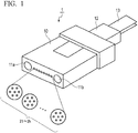
- FIG. 1 is a perspective view showing an external appearance of an optical connector according to one embodiment of the present invention.
- the optical connector 1 is composed of a Mechanically Transferable (MT) type optical connector, and includes an MT ferrule 10, a ribbon fiber 13, and a boot 12 protecting the ribbon fiber 13 at an end portion of the MT ferrule 10.
- Reference numerals 11a and 11b denote guide pin holes, and guide pins (not shown) of the optical connector to be connected at the time of the optical connector connection are inserted when the optical connector is connected.
- an accommodating portion of a cavity having a rectangular transverse cross-sectional shape there is provided an accommodating portion of a cavity having a rectangular transverse cross-sectional shape, and at least one multi-core block is accommodated in the accommodating portion.
- multi-core blocks Several examples relating to multi-core blocks will be described below.
- FIG. 2 is a perspective view showing a first example of multi-core blocks
- FIG. 3 is a view showing a state where the multi-core blocks are accommodated in the MT ferrule 10.
- the multi-core blocks 41 to 44 are accommodated in the accommodating portion of the MT ferrule 10 in a state where they are aligned in a row in the lateral direction (horizontal direction) in the drawing. At this time, the multi-core blocks 41 to 44 are disposed in close contact with each other and so that no gap is formed between the inner walls of the accommodating portion of the MT ferrule 10.
- FIG. 4 is a perspective view showing a second example of multi-core blocks
- FIG. 5 is a view showing a state where the multi-core blocks are accommodated in the MT ferrule 10.
- the multi-core block 30 is accommodated in a state where the upper and lower surfaces and the respective side surfaces are in contact with the inner wall surface of the accommodating portion provided in the MT ferrule 10.
- FIG. 6A shows a first configuration example of the present Example.
- FIG. 6B shows a second configuration example of the present Example.
- a total of thirty-two multi-core optical fibers 21 to 2k are distributed in a plurality of multi-core blocks and are fixed and held in a state where the respective plurality of multi-core blocks are arranged in a matrix, and the multi-core blocks are arranged side by side and are accommodated in the MT ferrule 10.
- the multi-core optical fibers 21 to 2k are fixed and held in a state of being arranged collectively in a matrix in one multi-core block.
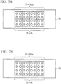
- FIG. 7A shows a first configuration example of the present embodiment.
- four multi-core blocks 71 to 7mxn are arranged side by side in the lateral direction and in two layers in the vertical direction, and is accommodated in the accommodating portion of the MT ferrule 10 in a state where the side surface is in contact with the inner wall surface of the accommodating portion of the MT ferrule 10.
- the eight multi-core blocks 71 to 7mxn are arranged in the MT ferrule 10 in a state where four of the multi-core blocks are arranged in the lateral direction and two of the multi-core blocks are arranged in the vertical direction.
- FIG. 7B shows a second configuration example.
- FIG. 7C shows a third configuration example.
- FIG. 7D shows a fourth configuration example.
- the multi-core block 90 is accommodated in a state where the upper and lower surfaces and the respective side surfaces are in contact with the inner wall surface of the accommodating portion of the MT ferrule 10 as shown in FIG. 7D .
- the thirty-two multi-core optical fibers 21 to 2k are fixed and held in a state of being arranged in a 2x8 matrix on one multi-core block 90, and the multi-core block 90 is accommodated in the MT ferrule 10.
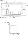
- the number (mxn) of the multi-core blocks accommodated in the MT ferrule 10 is set as follows. Hereinafter, descriptions will be made with reference to FIG. 8A to 8C and FIG. 9 .
- each multi-core block has clearance of ⁇ a and ⁇ b with respect to the design value axb of the outer size of the multi-core block.
- the multi-core block rotates with the clearance within a range of a maximum of m ⁇ a/2 and n ⁇ b/2 in the accommodating portion of the MT ferrule 10 as shown in FIG. 8C .
- the rotation angle is the smaller one of ⁇ x- ⁇ or ⁇ - ⁇ y, and the allowable angle of these rotation angles is expressed by the following formulas.
- ⁇ x ⁇ ⁇ sin ⁇ 1 a + m ⁇ ⁇ ⁇ a a 2 + b 2 ⁇ sin ⁇ 1 a a 2 + b 2 ⁇ Allowable rotation angle
- ⁇ ⁇ ⁇ y sin ⁇ 1 a a 2 + b 2 ⁇ cos ⁇ 1 b + n ⁇ ⁇ ⁇ b a 2 + b 2 ⁇ Allowable rotation angle
- the number (mxn) of multi-core blocks to be accommodated in the MT ferrule 10 is determined.
- the array number m in the lateral direction of the multi-core block and the lamination number n in the vertical direction in the accommodating portion must be a number equal to or less than the integer value of each line shown in FIG. 9 .
- the solid line and the broken line are the results when the allowable angle is 1 degree and 0.5 degrees respectively, and the marks of circle, triangle, square and rhombus are the results when clearance is respectively 1, 3, 5, and 10 ⁇ m.
- m is set to 5 or less in order to set the allowable rotation angle 1 degree or less.
- MCF multi-core optical fibers
- the rotation angle deviation can be reduced to about 0.4 degrees at the maximum.
- the connection loss can be improved to 0.05 dB or less.
- the rotation angle deviation can be reduced to about 0.7 degree at the maximum, so that the connection loss can be improved to 0.1 dB or less.
- the number mxn of the multi-core blocks in the accommodating portion is set to an appropriate value.
- the connection loss due to the rotation angle deviation of the multi-core block can be greatly reduced.
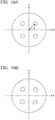
- FIGS. 10A and 10B show examples of axis misalignment of the core position at the connection point due to the rotation angle deviation using the 4-core fiber as an example.
- the distance between the center of each core and the center of the cladding including these cores is E
- the axial shift amount d between the cores at the connection point when the rotation angle deviation ⁇ occurs can be obtained from the cosine theorem of the trigonometric function as follows.
- d 2 E 2 ⁇ 2 E 2 cos ⁇
- connection loss ⁇ (dB) is obtained from the mode field diameter MFD of the fiber by the following formula.
- W MFD/2.
- ⁇ 10 log 10 exp ⁇ 2 d 2 2 W 2
- FIG. 11 is a graph showing a relationship between the rotation angle deviation and the connection loss with respect to the core.
- the MFD of the core 9.0 ⁇ m is employed which is within the MFD range described in ITU-T global standard recommendation G.652 (single mode optical fiber).
- E is the same for all cores in the example of the 4-core fiber, but in general, E is not always the same in all cores.
- the allowable rotation angle deviation is determined from the rotation angle deviation that is less than the allowable connection loss for the core with the largest E.
- the plurality of multi-core optical fibers 21 to 2k are fixed and held in one multi-core block 30 and are accommodated in an accommodating portion in the MT ferrule 10.
- the plurality of the multi-core optical fibers 21 to 2k is divided into several fibers and are distributed in the multi-core blocks 41 to 44 respectively, and are fixed and held, the number of which is smaller than the number of the multi-core optical fibers 21 to 2k.
- the multi-core blocks 41 to 44 are arranged side by side and are accommodated in the accommodating portion of the MT ferrule 10.
- the accommodation number of the multi-core block can be set to an optimum number according to the size of the accommodating portion of the MT ferrule 10, the size of the multi-core block, and the allowable rotation angle.
- the connection loss due to the rotation angle deviation of the multi-core block can be greatly reduced.
- the cross-sectional shape may be other shapes such as rhombus and trapezoid, and it is more preferable if the shape is such that the rotation of the block hardly occurs.
- the material of the block is not limited to a resin.
- the arrangement number and arrangement pattern of multi-core optical fibers in multi-core blocks the number of multi-core blocks to be accommodated in ferrules and the arrangement pattern thereof, the number of multi-core optical fibers accommodated in one optical connector, and the number of multi-core blocks and the like can also be implemented with various modifications without departing from the gist of the present invention.
- the present invention is not limited to the above-described embodiments, but can be embodied by modifying constituent elements without departing from the gist thereof.
- a plurality of constituent elements disclosed in the above embodiment may be appropriately combined.
- some constituent elements may be deleted from all the constituent elements shown in the embodiment.
- the constituent elements over different embodiments may be appropriately combined.
Landscapes
- Physics & Mathematics (AREA)
- General Physics & Mathematics (AREA)
- Optics & Photonics (AREA)
- Mechanical Coupling Of Light Guides (AREA)
Abstract
Description
- The present invention relates to an optical connector connecting a multi-core optical fiber.
- Priority is claimed on Japanese Patent Application No.
2016-132511 - When multi-core optical fibers are connected by optical connectors, it is necessary to align the cores of the optical fibers. For alignment, there are a method of adjusting a position in the horizontal and vertical directions in the cross-section of the optical fiber and a method of adjusting a rotation angle where a center axis corresponds to the longitudinal direction of the optical fiber (see, for example, Non-Patent Document 1).
- In a multi-fiber optical connector that connects a plurality of multi-core optical fibers collectively, a method using individual blocks has been proposed as a method of adjusting a rotation angle of a plurality of multi-core optical fibers. In such a method, a plurality of multi-core optical fibers are accommodated in individual blocks, respectively, and the rotation angle is aligned. The plurality of aligned individual blocks are arranged side by side and are accommodated in an accommodating portion in a ferrule (for example, see Patent Document 2).
-
- [Non-Patent Document 1] R. Nagase, K. Sakaime, K. Watanabe, and T. Saito, "MU-Type Multi-core Fiber Connector", Trans. IEICE, Vol. E96-C, No. 9, pp. 1173-1177, (2013).
- [Non-Patent Document 2] K. Watanabe, T. Saito, K. Kawasaki, M. Iwaya, T. Ando, K. Suematsu, M. Shiino, "Development of MPO type 8-multi-core fiber connector", in Proc. OFC2015, W4B.3, (2015).
- However, according to the method described in Non-Patent
Document 2, since each of the plurality of individual blocks has clearance, as the number of the multi-core optical fibers increases, the clearance of the individual block is integrated. As a result, a large axis deviation may be caused. As the axis misalignment, there are axial misalignment in the rotation direction of the optical fiber due to clearance and axial misalignment of the vertical and horizontal directions with respect to a cross-section of the optical fiber. - The present invention has been made in view of the above circumstances, an optical connector in which clearance between blocks fixing and holding each of the multi-core optical fibers is reduced to enable highly accurate alignment when accommodating a plurality of multi-core optical fibers is provided.
- A first aspect of the present invention is an optical connector including: at least one multi-core block fixing and holding a plurality of multi-core optical fibers in a state where a position in a direction orthogonal to an optical axis of each multi-core optical fiber and a rotation angle around the optical axis are in a predetermined state; and a ferrule including an accommodating portion accommodating the multi-core block.
- A second aspect of the present invention is the optical connector according to the first aspect, and it is preferable that the multi-core block has a rectangular cross-sectional shape having a clearance with respect to a design value, the accommodating portion of the ferrule has a rectangular cross-sectional shape ; and when an allowable value of a rotation angle of rotation of the multi-core block in an optical axis direction in the accommodating portion of the ferrule is determined, the larger the clearance is, the smaller a number of the multi-core blocks to be accommodated in the accommodating portion of the ferrule is, and the smaller the allowable value of the rotation angle is, the smaller the number of the multi-core blocks to be accommodated in the accommodating portion of the ferrule is.
- A third aspect of the present invention is the optical connector according to the second aspect, and it is preferable that the cross-sectional shape of the multi-core block is an axb rectangle having a clearance of Δa and Δb with respect to a design value, the cross-sectional shape of the accommodating portion of the ferrule is an xxy rectangle; and the number mxn of the multi-core blocks to be accommodated in the accommodating portion of the ferrule is determined so that the allowable rotation angle of the multi-core block in the accommodating portion of the ferrule satisfies both the following formulas (1) and (2)..
(Formula 1)

- A fourth aspect of the present invention is the optical connector according to the third aspect, and it is preferable that in the number mxn of the multi-core blocks accommodated in the accommodating portion of the ferrule, n=1 and m≤5.
- A fifth aspect of the present invention is the optical connector according to the third aspect, and it is preferable that in the number mxn of the multi-core blocks accommodated in the accommodating portion of the ferrule, n=2 and m≤5.
- A sixth aspect of the present invention is the optical connector according to the third aspect, where the multi-core block preferably rotates with a clearance within a range of a maximum of m·Δa/2 and n·Δb/2 in the accommodating portion of the ferrule.
- A seventh aspect of the present invention is the optical connector according to the first aspect, where each of the multi-core optical fibers includes a plurality of cores and a cladding surrounding the plurality of cores, and in the plurality of cores, it is preferable that each of a distance between a core center and a center of the cladding is equal to each other, and has allowable rotation angle deviation determined based on the distance.
- An eighth aspect of the present invention is the optical connector according to the first aspect, and it is preferable that where each of the multi-core optical fibers includes a plurality of cores and a cladding surrounding the plurality of cores, in the plurality of cores, a distance between at least one core center and a center of the cladding is different from a distance between the other remaining core centers and the center of the cladding, and has allowable rotation angle deviation which is determined based on a maximum distance.
- According to the above aspects of the present invention, the multi-core block in which the plurality of multi-core optical fibers are collectively fixed and held is accommodated in the accommodating portion in the ferrule. Therefore, compared with the case where a plurality of multi-core optical fibers are fixed and held individually by blocks, and these blocks are arranged side by side and are accommodated in a ferrule, the clearance between the blocks can be reduced and highly accurate positioning can be performed.
- In addition, the smaller the allowable rotation angle of the multi-core block in the accommodating portion of the ferrule is, the smaller the number of multi-core blocks to be accommodated is set, and the larger the above-described clearance is, the smaller the number of multi-core blocks to be accommodated is set. In this manner, the accommodation number of the multi-core block can be set to an optimum number according to the size of the accommodating portion of the ferrule, the size of the multi-core block, and the allowable rotation angle. As a result, the connection loss due to the rotation angle deviation of the multi-core block can be greatly reduced.
- That is, according to the above-described aspects of the present invention, an optical connector in which a clearance between blocks fixing and holding each of the multi-core optical fibers is reduced to enable highly accurate alignment when accommodating a plurality of multi-core optical fibers can be provided.
-
-
FIG. 1 is a perspective view showing an external appearance of an optical connector according to an embodiment of the present invention. -
FIG. 2 is a perspective view showing a first example of multi-core blocks accommodated in the optical connector shown inFIG. 1 . -
FIG. 3 is a transverse cross-sectional view showing a state in which the multi-core blocks shown inFIG. 2 is accommodated in the optical connector shown inFIG. 1 . -
FIG. 4 is a perspective view showing a second example of multi-core blocks accommodated in the optical connector shown inFIG. 1 . -
FIG. 5 is a transverse cross-sectional view showing a state in which the multi-core blocks shown inFIG. 4 is accommodated in the optical connector shown inFIG. 1 . -
FIG. 6A is a transverse cross-sectional view showing a state in which multi-core blocks according to a third example of the present invention is accommodated in an optical connector. -
FIG. 6B is a transverse cross-sectional view showing a state in which multi-core blocks according to a third example of the present invention is accommodated in an optical connector. -
FIG. 7A is a transverse cross-sectional view showing a state in which multi-core blocks according to a fourth example of the present invention is accommodated in an optical connector. -
FIG. 7B is a transverse cross-sectional view showing a state in which multi-core blocks according to a fourth example of the present invention is accommodated in an optical connector. -
FIG. 7C is a transverse cross-sectional view showing a state in which multi-core blocks according to a fourth example of the present invention is accommodated in an optical connector. -
FIG. 7D is a transverse cross-sectional view showing a state in which multi-core blocks according to a fourth example of the present invention is accommodated in an optical connector. -
FIG. 8A is a diagram describing a relationship between clearance and a rotation angle of multi-core blocks. -
FIG. 8B is a diagram describing a relationship between clearance and a rotation angle of multi-core blocks. -
FIG. 8C is a diagram describing a relationship between clearance and a rotation angle of multi-core blocks. -
FIG. 9 is a graph showing an upper limit value of the number of multi-core blocks arranged in a two-dimensional direction, which is set according to the clearance and the rotation angle of multi-core blocks. -
FIG. 10A is a view showing an example of axial misalignment of a core position due to a rotation angle deviation in a 4-core fiber. -
FIG. 10B is a view showing an example of axial misalignment of a core position due to a rotation angle deviation in a 4-core fiber. -
FIG. 11 is a graph showing a relationship between the rotation angle deviation and the connection loss with respect to the core. - Hereinafter, embodiments of the present invention will be described with reference to the drawings.
-
FIG. 1 is a perspective view showing an external appearance of an optical connector according to one embodiment of the present invention. Theoptical connector 1 is composed of a Mechanically Transferable (MT) type optical connector, and includes anMT ferrule 10, aribbon fiber 13, and aboot 12 protecting theribbon fiber 13 at an end portion of theMT ferrule 10.Reference numerals - Inside the
MT ferrule 10, there is provided an accommodating portion of a cavity having a rectangular transverse cross-sectional shape, and at least one multi-core block is accommodated in the accommodating portion. Several examples relating to multi-core blocks will be described below. -
FIG. 2 is a perspective view showing a first example of multi-core blocks, andFIG. 3 is a view showing a state where the multi-core blocks are accommodated in theMT ferrule 10. - In the first example, four
multi-core blocks 41 to 44 which are rectangular shape are used. Each of themulti-core blocks 41 to 44 has two insertion holes, and the multi-coreoptical fibers 21 to 2k (k=8 in this embodiment) are inserted into these insertion holes. In this case, the formation position of the insertion hole in themulti-core blocks 41 to 44 defines the accuracy in a two-dimensional direction orthogonal to the optical axis of the multi-coreoptical fibers 21 to 2k (k=8). In addition, the rotation angle around the optical axis of the multi-coreoptical fibers 21 to 2k (k=8) is aligned so as to be at the same predetermined angle with respect to the upper side of themulti-core blocks 41 to 44. - As shown in
FIG. 3 , themulti-core blocks 41 to 44 are accommodated in the accommodating portion of theMT ferrule 10 in a state where they are aligned in a row in the lateral direction (horizontal direction) in the drawing. At this time, themulti-core blocks 41 to 44 are disposed in close contact with each other and so that no gap is formed between the inner walls of the accommodating portion of theMT ferrule 10. - With such a configuration, in an optical connector that collectively accommodates the eight multi-core
optical fibers 21 to 2k (k=8), the multi-coreoptical fibers 21 to 2k (k=8) are fixed and held in a pair with the fourmulti-core blocks 41 to 44. Therefore, alignment accuracy of the multi-coreoptical fibers 21 to 2k (k=8) is an integrated value of the clearance of the fourmulti-core blocks 41 to 44. As a result, as compared with the case where each one of the multi-coreoptical fibers 21 to 2k (k=8) is accommodated in a block and eight blocks in total are accommodated in the MT ferrule, the clearance between the blocks is reduced to a half, and it is possible to improve the alignment accuracy of the multi-coreoptical fibers 21 to 2k (k=8). -
FIG. 4 is a perspective view showing a second example of multi-core blocks, andFIG. 5 is a view showing a state where the multi-core blocks are accommodated in theMT ferrule 10. - In the multi-core block of the second example, eight insertion holes are provided in a row in one flat plate-like
multi-core block 30, eight multi-coreoptical fibers 21 to 2k (k=8) are inserted in the insertion hole, and the rotation angles of the respective axes are aligned. The eight insertion holes define positional accuracy in a two-dimensional direction orthogonal to the optical axis of the multi-coreoptical fibers 21 to 2k (k=8). As shown inFIG. 5 , themulti-core block 30 is accommodated in a state where the upper and lower surfaces and the respective side surfaces are in contact with the inner wall surface of the accommodating portion provided in theMT ferrule 10. - With such a configuration, in an optical connector that collectively accommodates eight multi-core
optical fibers 21 to 2k (k=8), eight multi-coreoptical fibers 21 to 2k (k=8) is fixed and held in oneblock 30. Therefore, the alignment accuracy of the multi-coreoptical fibers 21 to 2k (k=8) is determined by the clearance of only onemulti-core block 30. As a result, as compared with a case where each one of the multi-coreoptical fibers 21 to 2k (k=8) is accommodated in a block and eight blocks in total are accommodated in theMT ferrule 10, the clearance between the blocks is reduced to one-eighth to further improve the alignment accuracy of the multi-coreoptical fibers 21 to 2k (k=8). - In a third Example, a total of thirty-two multi-core
optical fibers 21 to 2k (k=32) are distributedly arranged in a plurality of multi-core blocks and are fixed and held in a state where the respective plurality of multi-core blocks are arranged in a row in each multi-core block, and these multi-core blocks are accommodated in theMT ferrule 10 in a stacked state. -
FIG. 6A shows a first configuration example of the present Example. In the first configuration example, eight multi-core blocks each having a flat plate shape with four insertion holes formed in a row are prepared, and in thesemulti-core blocks 51 to 5mxn (m=8, n=1), four of the thirty-two multi-coreoptical fibers 21 to 2k (k=32) in total are inserted into the insertion hole of theoptical fiber 21 to 2k (k=32) and are fixed and held. The four insertion holes in each of themulti-core blocks 51 to 5m×n (m=8, n=1) define the positional accuracy in the two-dimensional direction orthogonal to the optical axis of the multi-coreoptical fibers 21 to 2k (k=32). The multi-core blocks 51 to 5mxn (m=8, n=1) are accommodated in the accommodating portion of theMT ferrule 10 in a state of being aligned in the lateral direction as shown inFIG. 6A . - With such a configuration, in an optical connector that collectively accommodates thirty-two multi-core
optical fibers 21 to 2k (k=32), four of the thirty-two multi-coreoptical fibers 21 to 2k (k=32) are distributed, fixed and held in eightmulti-core blocks 51 to 5mxn (m=8, n=1), and the eightmulti-core blocks 51 to 5mxn (m=8, n=1) are accommodated in theMT ferrule 10 in a state of being aligned in a row. - For this reason, the alignment accuracy of the multi-core
optical fibers 21 to 2k (k=32) is determined by the integrated value of the clearance of eightmulti-core blocks 51 to 5m (m=8) in the lateral direction, and is determined by the individual clearance of themulti-core blocks 51 to 5n (n=1) in the vertical direction. As a result, compared with the case where the multi-coreoptical fibers 21 to 2k (k=32) are accommodated one by one in a block and a total of thirty-two blocks is accommodated in the accommodating portion of theMT ferrule 10, the clearance between the blocks is greatly reduced, thereby making it possible to improve the alignment accuracy of the multi-coreoptical fibers 21 to 2k (k=32). -
FIG. 6B shows a second configuration example of the present Example. In the second configuration example, as shown inFIGS. 4 and 5 , four multi-core blocks each having a flat plate with eight insertion holes are formed in a row are prepared, and in these multi-core blocks 61 to 6n (n=4), a total of thirty-two multi-coreoptical fibers 21 to 2k (k=32) are fixed and held in the respective insertion holes. The eight insertion holes in each of the multi-core blocks 61 to 6n (n=4) define the positional accuracy in the two-dimensional direction orthogonal to the optical axis of the multi-coreoptical fibers 21 to 2k (k=32). As shown inFIG. 6B , the multi-core blocks 61 to 6m×n (m=1, n=4) described above are accommodated in the accommodating portion of theMT ferrule 10 in a state of being stacked in four layers in the vertical direction. - With such a configuration, in an optical connector that collectively accommodates thirty-two multi-core
optical fibers 21 to 2k (k=32), eight of the thirty-two multi-coreoptical fibers 21 to 2k (k=32) are distributed in four multi-core blocks 61 to 6mxn (m=1, n=4), and are fixed and held in a state of being arranged in a row in the lateral direction. The four multi-core blocks 61 to 6m×n (m=1, n=4) are accommodated in theMT ferrule 10 in a state of being stacked in four layers in the vertical direction. - Therefore, the alignment accuracy of the multi-core
optical fibers 21 to 2k (k=32) is determined by the integrated value of the clearance of the four multi-core blocks 61 to 6n (n=4) in the vertical direction, and is determined by the individual clearance of the multi-core blocks 61 to 6m (m=1) in the lateral direction. As a result, as compared with the case where each one of the multi-coreoptical fibers 21 to 2k (k=32) is accommodated in a block and thirty-two blocks in total are accommodated in the MT ferrule, the clearance between the blocks can be greatly reduced to improve the alignment accuracy of the multi-coreoptical fibers 21 to 2k (k=32). - In a fourth Example, a total of thirty-two multi-core
optical fibers 21 to 2k (k=32) are distributed in a plurality of multi-core blocks and are fixed and held in a state where the respective plurality of multi-core blocks are arranged in a matrix, and the multi-core blocks are arranged side by side and are accommodated in theMT ferrule 10. In addition, the multi-coreoptical fibers 21 to 2k (k=32) are fixed and held in a state of being arranged collectively in a matrix in one multi-core block. -
FIG. 7A shows a first configuration example of the present embodiment. In the first configuration example, eight multi-core blocks, which are quadrangular prisms in which four insertion holes are formed in a 2x2 matrix, are prepared, and in the insertion hole of each of thesemulti-core blocks 71 to 7m×n (m=4, N=2), four of the thirty-two multi-coreoptical fibers 21 to 2k (k=32) are distributed, and are fixed and held in a state of being arranged in a matrix. - The four insertion holes in each of the
multi-core blocks 71 to 7m×n (m=4, n=2) are positioned in the two-dimensional direction orthogonal to the optical axis of the multi-coreoptical fibers 21 to 2k (k=32). As shown inFIG. 7A , fourmulti-core blocks 71 to 7mxn (m=4, n=2) are arranged side by side in the lateral direction and in two layers in the vertical direction, and is accommodated in the accommodating portion of theMT ferrule 10 in a state where the side surface is in contact with the inner wall surface of the accommodating portion of theMT ferrule 10. - With such a configuration, in an optical connector that collectively accommodates thirty-two multi-core
optical fibers 21 to 2k (k=32), four of the thirty-two multi-coreoptical fibers 21 to 2k (k=32) are distributed in eightmulti-core blocks 71 to 7mxn (m=4, n=2), and are fixed and held in a state of being arranged in a matrix. In addition, as shown inFIG. 7A , the eightmulti-core blocks 71 to 7mxn (m=4, n=2) are arranged in theMT ferrule 10 in a state where four of the multi-core blocks are arranged in the lateral direction and two of the multi-core blocks are arranged in the vertical direction. - Therefore, the alignment accuracy of the multi-core
optical fibers 21 to 2k (k=32) is determined by the integrated value of clearance of the fourmulti-core blocks 71 to 7m (m=4) in the lateral direction, and is determined by the integrated value of clearance of the twomulti-core blocks 71 to 7n (n=2) in the vertical direction. As a result, as compared with the case where each one of the multi-coreoptical fibers 21 to 2k (k=32) is accommodated in a block and thirty-two blocks in total are accommodated in the MT ferrule, the clearance between the blocks can be greatly reduced to improve the alignment accuracy of the multi-coreoptical fibers 21 to 2k (k=32). -
FIG. 7B shows a second configuration example. In the second configuration example, four multi-core blocks, which are quadrangular prisms in which eight insertion holes are formed in a matrix of 2x4, are prepared, and in the insertion hole of each of thesemulti-core blocks 81 to 8m×n (m=4, n=1), a total of thirty-two multi-coreoptical fibers 21 to 2k (k=32) are distributed, and are fixed and held in a state of being arranged in a matrix. - The eight insertion holes in each of the
multi-core blocks 81 to 8mxn (m=4, n=1) are positioned in the two-dimensional direction orthogonal to the optical axis of the multi-coreoptical fibers 21 to 2k (k=32). As shown inFIG. 7B , four side-by-side blocks 81 to 8mxn (m=4, n=1) are arranged in the lateral direction so that the upper and lower surfaces and the respective side surfaces are positioned within the accommodating portion of theMT ferrule 10, and are accommodated in the accommodating portion of theMT ferrule 10 in a state of being in contact with the wall surface. - With such a configuration, in an optical connector that collectively accommodates thirty-two multi-core
optical fibers 21 to 2k (k=32), eight of the thirty-two multi-coreoptical fibers 21 to 2k (k=32) are distributed in fourmulti-core blocks 81 to 8mxn (m=4, n=1), and are fixed and held in a state of being arranged in a matrix. The fourmulti-core blocks 81 to 8m×n (m=4, n=1) are accommodated in theMT ferrule 10 in a state of being arranged in the lateral direction. - For this reason, the alignment accuracy of the multi-core
optical fibers 21 to 2k (k=32) is determined by the integrated value of the clearance of the fourmulti-core blocks 81 to 8 m (m=4) in the lateral direction, and is determined only by the clearance of the individualmulti-core blocks 81 to 8n (n=1) in the vertical direction. As a result, as compared with the case where one of the multi-coreoptical fibers 21 to 2k (k=32) is accommodated in each block and thirty-two blocks in total are accommodated in the MT ferrule, the clearance between the blocks can be reduced and it is possible to improve the alignment accuracy of the multi-coreoptical fibers 21 to 2k (k=32). -
FIG. 7C shows a third configuration example. In the third configuration example, two multi-core blocks, which are quadrangular prisms in which sixteen insertion holes are formed in a matrix of 2x8 are prepared, and in each of the insertion holes of thesemulti-core blocks 91 to 9m×n (m=1, n=2), a total of thirty-two multi-coreoptical fibers 21 to 2k (k=32) are distributed, and are fixed and held in a state of being arranged in a matrix of 2x8 in total. - The sixteen insertion holes in each of the
multi-core blocks 91 to 9m×n (m=1, n=2) have positional accuracy in the two-dimensional direction orthogonal to the optical axis of the multi-coreoptical fibers 21 to 2k (k=32). As shown inFIG. 7C , in a state where themulti-core blocks 91 to 9m×n (m=1, n=2) are stacked in two layers in the vertical direction, upper and lower surfaces and side surfaces of the accommodating portion of theMT ferrule 10 and is accommodated in the accommodating portion of theMT ferrule 10 in a state of being in contact with the inner wall surface. - With such a configuration, in an optical connector that collectively accommodates thirty-two multi-core
optical fibers 21 to 2k (k=32), sixteen of the thirty-two multi-coreoptical fibers 21 to 2k (k=32) are distributed in twomulti-core blocks 91 to 9mxn (m=1, n=2), and are fixed and held in a state of being arranged in a 2x8 matrix. The twomulti-core blocks 91 to 9mxn (m=1, n=2) are stacked in two layers in the vertical direction and accommodated in theMT ferrule 10. - Therefore, the alignment accuracy of the multi-core
optical fibers 21 to 2k (k=32) is determined by the integrated value of the clearance of the twomulti-core blocks 91 to 9n (n=2) in the vertical direction, and in the longitudinal direction, it is determined only by the individual clearance of themulti-core blocks 91 to 9m (m=1). As a result, as compared with the case where each one of the multi-coreoptical fibers 21 to 2k (k=32) is accommodated in a block and thirty-two blocks in total are accommodated in the MT ferrule, the clearance between the blocks can be reduced to improve the alignment accuracy of the multi-coreoptical fibers 21 to 2k (k=32). -
FIG. 7D shows a fourth configuration example. In the fourth configuration example, one multi-core block, which is a quadrangular prism having thirty-two insertion holes formed in a matrix of 8x4, is prepared, and in each insertion hole of themulti-core block 90, a total of thirty-two multi-coreoptical fibers 21 to 2k (k=32) is fixed and held in a state of being arranged in a matrix of 8x4. Thirty-two insertion holes in each of themulti-core block 90 define positional accuracy in a two-dimensional direction orthogonal to the optical axis of the multi-coreoptical fibers 21 to 2k (k=32). Themulti-core block 90 is accommodated in a state where the upper and lower surfaces and the respective side surfaces are in contact with the inner wall surface of the accommodating portion of theMT ferrule 10 as shown inFIG. 7D . - With such a configuration, in an optical connector that collectively accommodates thirty-two multi-core
optical fibers 21 to 2k (k=32), the thirty-two multi-coreoptical fibers 21 to 2k (k=32) are fixed and held in a state of being arranged in a 2x8 matrix on onemulti-core block 90, and themulti-core block 90 is accommodated in theMT ferrule 10. - Therefore, the alignment accuracy of the multi-core
optical fibers 21 to 2k (k=32) is determined only by the clearance of onemulti-core block 90 in both the vertical direction and the longitudinal direction. As a result, as compared with the case where one of the multi-coreoptical fibers 21 to 2k (k=32) is accommodated in each block and thirty-two blocks in total are accommodated in the MT ferrule, the clearance between the blocks can be greatly reduced and to further improve the alignment accuracy of the multi-coreoptical fibers 21 to 2k (k=32). - The number (mxn) of the multi-core blocks accommodated in the
MT ferrule 10 is set as follows. Hereinafter, descriptions will be made with reference toFIG. 8A to 8C andFIG. 9 . - That is, the size of the accommodating portion of the
MT ferrule 10 is xxy (mm) as shown inFIG. 8A , and mxn multi-core blocks are accommodated in the accommodating portion of theMT ferrule 10. Furthermore, as shown inFIG. 8B , each multi-core block has clearance of Δa and Δb with respect to the design value axb of the outer size of the multi-core block. Under the above conditions, the multi-core block rotates with the clearance within a range of a maximum of m·Δa/2 and n·Δb/2 in the accommodating portion of theMT ferrule 10 as shown inFIG. 8C . - The rotation angle is the smaller one of θx-θ or θ-θy, and the allowable angle of these rotation angles is expressed by the following formulas.
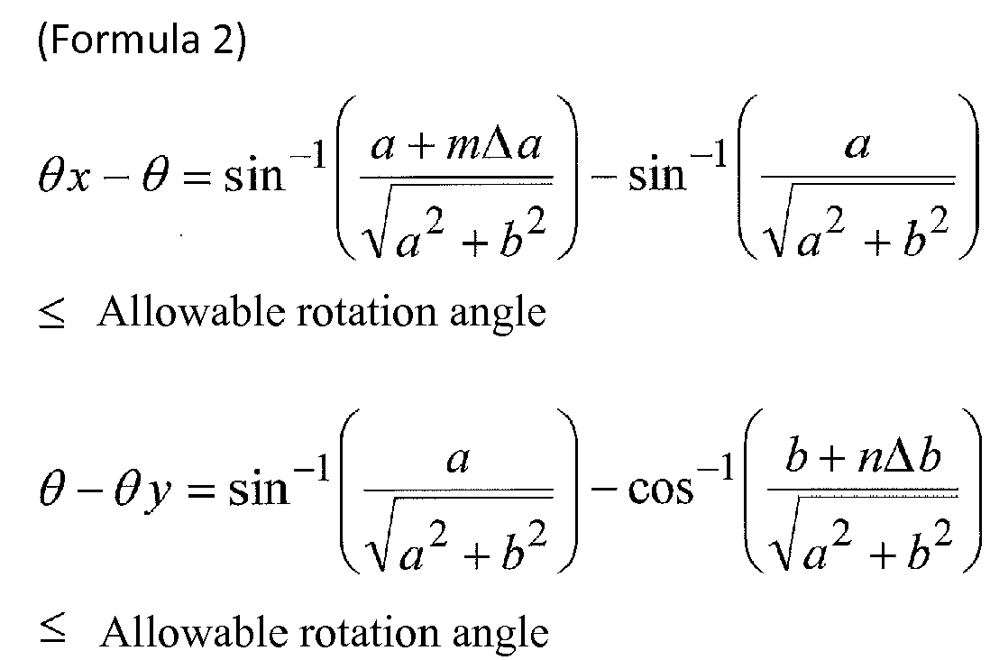
- In order to satisfy this condition, the number (mxn) of multi-core blocks to be accommodated in the
MT ferrule 10 is determined. - For example, when the size of the accommodating portion of the
MT ferrule 10 accommodating the multi-core block is x=3.2 mm and y=1.8 mm, depending on the angle at which the multi-core block can rotate in the accommodating portion and the clearance of the multi-core block, the array number m in the lateral direction of the multi-core block and the lamination number n in the vertical direction in the accommodating portion must be a number equal to or less than the integer value of each line shown inFIG. 9 . Also, when y=1.0 mm and y=0.5 mm, the same number or less is obtained. - In
FIG. 9 , the solid line and the broken line are the results when the allowable angle is 1 degree and 0.5 degrees respectively, and the marks of circle, triangle, square and rhombus are the results when clearance is respectively 1, 3, 5, and 10 µm. For example, when n=1, if the clearance is 5 µm, m is set to 5 or less in order to set the allowable rotation angle to 0.5 degrees or less. Also, even when n=2, m is set to 5 or less in order to set the allowable rotation angle equal to or less than 0.5 degrees. In addition, when n=1 and the clearance is 10 µm, m is set to 5 or less in order to set theallowable rotation angle 1 degree or less. - That is, as is clear from
FIG. 9 , the smaller the allowable rotation angle is, the smaller the numbers of m and n are. Also, the larger the clearance is, the smaller the numbers of m and n are. In particular, when n=1 and n=2, it is preferable to set m≤5. - One block is used for each of the eight multi-core optical fibers (MCF) described in
Non-Patent Document 2, and eight blocks are placed in the MT ferrule with n=1 and m=8. When accommodated, in a block with clearance of 10 µm, rotation angle deviation is generated by up to 3 degrees at the maximum with respect to the opposing multi-core optical fiber to be connected. As a result, connection loss close to 1 dB may occur. - In contrast, for example, as shown in
FIG. 4 , eight multi-coreoptical fibers 21 to 2k (k=8) are fixed and held in a single multi-core block in a row, and when themulti-core block 30 is accommodated in theMT ferrule 10 as n=1 and m=1 as shown inFIG. 5 , the rotation angle deviation can be reduced to about 0.4 degrees at the maximum. As a result, the connection loss can be improved to 0.05 dB or less. Even when n=2, the rotation angle deviation can be reduced to about 0.7 degree at the maximum, so that the connection loss can be improved to 0.1 dB or less. - That is, according to the size of the accommodating portion of the
MT ferrule 10, the clearance of the multi-core block, and the allowable rotation angle of the multi-core block in the accommodating portion, the number mxn of the multi-core blocks in the accommodating portion is set to an appropriate value. The connection loss due to the rotation angle deviation of the multi-core block can be greatly reduced. - Acceptable rotation angle deviation is determined by the allowable connection loss and the core arrangement structure of the multi-core fiber.
FIGS. 10A and 10B show examples of axis misalignment of the core position at the connection point due to the rotation angle deviation using the 4-core fiber as an example. Assuming that the distance between the center of each core and the center of the cladding including these cores (the origin on the xy axis plane in the drawing) is E, the axial shift amount d between the cores at the connection point when the rotation angle deviation θ occurs (the core position is indicated by a dotted line inFIG. 10B ), can be obtained from the cosine theorem of the trigonometric function as follows.
- Furthermore, the connection loss α (dB) is obtained from the mode field diameter MFD of the fiber by the following formula. Here, W=MFD/2.

-
FIG. 11 is a graph showing a relationship between the rotation angle deviation and the connection loss with respect to the core. Here, the calculation results of the connection loss with respect to the rotation angle deviation when the core is set to E=30, 40, and 50 µm are shown. As the MFD of the core, 9.0 µm is employed which is within the MFD range described in ITU-T global standard recommendation G.652 (single mode optical fiber). - As shown in
FIG. 11 , the connection loss characteristic with respect to the rotation deviation greatly changes with respect to the distance E from the cladding center of the core, and it can be seen that the connection loss increases as E increases. Furthermore, for example, when E=30 µm, if it is attempted to reduce the connection loss to 0.1 dB or less, it is found that the allowable rotation angle deviation is 0.7°. On the other hand, when E=50 µm, the deviation is 0.4°, and the allowable rotation angle for the core with large E becomes small. - Here, E is the same for all cores in the example of the 4-core fiber, but in general, E is not always the same in all cores. For multi-core fibers with different E in each core, the allowable rotation angle deviation is determined from the rotation angle deviation that is less than the allowable connection loss for the core with the largest E.
- As described above in detail, according to one embodiment of the present invention, the plurality of multi-core
optical fibers 21 to 2k are fixed and held in onemulti-core block 30 and are accommodated in an accommodating portion in theMT ferrule 10. Alternatively, the plurality of the multi-coreoptical fibers 21 to 2k is divided into several fibers and are distributed in themulti-core blocks 41 to 44 respectively, and are fixed and held, the number of which is smaller than the number of the multi-coreoptical fibers 21 to 2k. The multi-core blocks 41 to 44 are arranged side by side and are accommodated in the accommodating portion of theMT ferrule 10. - Therefore, compared with the case where a plurality of multi-core
optical fibers 21 to 2k are fixed and held individually by blocks, and the blocks are arranged side by side and are accommodated in theMT ferrule 10, the clearance between the blocks is reduced and highly accurate positioning can be performed. - In addition, the smaller the allowable rotation angle of the multi-core block in the accommodating portion of the
MT ferrule 10 is, the smaller the number of multi-core blocks to be accommodated is set, and the larger the clearance above-described is, the smaller the number of multi-core blocks to be accommodated is set. In this manner, the accommodation number of the multi-core block can be set to an optimum number according to the size of the accommodating portion of theMT ferrule 10, the size of the multi-core block, and the allowable rotation angle. As a result, the connection loss due to the rotation angle deviation of the multi-core block can be greatly reduced. - In the above-described embodiment, a case where a flat plate-shaped or column-shaped resin block having a rectangular transverse cross-sectional shape is used as a multi-core block has been described as an example. However, the cross-sectional shape may be other shapes such as rhombus and trapezoid, and it is more preferable if the shape is such that the rotation of the block hardly occurs. Also, the material of the block is not limited to a resin.
- In addition, regarding the arrangement number and arrangement pattern of multi-core optical fibers in multi-core blocks, the number of multi-core blocks to be accommodated in ferrules and the arrangement pattern thereof, the number of multi-core optical fibers accommodated in one optical connector, and the number of multi-core blocks and the like can also be implemented with various modifications without departing from the gist of the present invention.
- The present invention is not limited to the above-described embodiments, but can be embodied by modifying constituent elements without departing from the gist thereof. In addition, a plurality of constituent elements disclosed in the above embodiment may be appropriately combined. For example, some constituent elements may be deleted from all the constituent elements shown in the embodiment. Furthermore, the constituent elements over different embodiments may be appropriately combined.
-
- 1: optical connector
- 10: ferrule
- 11a, 11b: guide pinhole
- 12: boot
- 13: ribbon fiber
- 21 to 2k: multi-core optical fiber
- 30, 41 to 44, 51 to 5m×n, 61 to 6m×n, 71 to 7m×n, 81 to 8m×n, 90, 91 to 9m×n: multi-core block
Claims (8)
- An optical connector comprising:at least one multi-core block fixing and holding a plurality of multi-core optical fibers in a state where a position in a direction orthogonal to an optical axis of each multi-core optical fiber and a rotation angle around the optical axis are in a predetermined state; anda ferrule comprising an accommodating portion accommodating the multi-core block.
- The optical connector according to Claim 1, wherein:the multi-core block has a rectangular cross-sectional shape having a clearance with respect to a design value;the accommodating portion of the ferrule has a rectangular cross-sectional shape;andwhen an allowable value of a rotation angle of the multi-core block in an optical axis direction in the accommodating portion of the ferrule is determined, the larger the clearance is, the smaller a number of the multi-core blocks to be accommodated in the accommodating portion of the ferrule is, and the smaller the allowable value of the rotation angle is, the smaller the number of the multi-core blocks to be accommodated in the accommodating portion of the ferrule is.
- The optical connector according to Claim 2, wherein:the cross-sectional shape of the multi-core block is an axb rectangle having a clearance of Δa and Δb with respect to a design value, the cross-sectional shape of the accommodating portion of the ferrule is an xxy rectangle; andthe number mxn of the multi-core blocks to be accommodated in the accommodating portion of the ferrule is determined so that the allowable rotation angle of the multi-core block in the accommodating portion of the ferrule satisfies both the following formulas (1) and (2).
(Formula 1)

- The optical connector according to Claim 3, wherein in the number mxn of the multi-core blocks accommodated in the accommodating portion of the ferrule, n=1 and m≤5.
- The optical connector according to Claim 3, wherein in the number mxn of the multi-core blocks accommodated in the accommodating portion of the ferrule, n=2 and m≤5.
- The optical connector according to Claim 3, wherein the multi-core block rotates with a clearance within a range of a maximum of m·Δa/2 and n·Δb/2 in the accommodating portion of the ferrule.
- The optical connector according to Claim 1, wherein each of the multi-core optical fibers comprises a plurality of cores and a cladding surrounding the plurality of cores;
in the plurality of cores, each of a distance between a core center and a center of the cladding is equal to each other; and
each of the multi-core optical fibers has allowable rotation angle deviation determined based on the distance. - The optical connector according to Claim 1, wherein each of the multi-core optical fibers comprises a plurality of cores and a cladding surrounding the plurality of cores;
in the plurality of cores, a distance between at least one core center and a center of the cladding is different from a distance between the other remaining core centers and the center of the cladding; and
each of the multi-core optical fibers has allowable rotation angle deviation which is determined based on a maximum distance.
Applications Claiming Priority (2)
| Application Number | Priority Date | Filing Date | Title |
|---|---|---|---|
| JP2016132511 | 2016-07-04 | ||
| PCT/JP2017/022828 WO2018008399A1 (en) | 2016-07-04 | 2017-06-21 | Optical connector |
Publications (3)
| Publication Number | Publication Date |
|---|---|
| EP3470898A1 true EP3470898A1 (en) | 2019-04-17 |
| EP3470898A4 EP3470898A4 (en) | 2020-02-12 |
| EP3470898B1 EP3470898B1 (en) | 2021-08-25 |
Family
ID=60912670
Family Applications (1)
| Application Number | Title | Priority Date | Filing Date |
|---|---|---|---|
| EP17824006.5A Active EP3470898B1 (en) | 2016-07-04 | 2017-06-21 | Method of manufacturing an optical connector |
Country Status (5)
| Country | Link |
|---|---|
| US (1) | US10585235B2 (en) |
| EP (1) | EP3470898B1 (en) |
| JP (1) | JP6616509B2 (en) |
| CN (1) | CN109219765B (en) |
| WO (1) | WO2018008399A1 (en) |
Cited By (2)
| Publication number | Priority date | Publication date | Assignee | Title |
|---|---|---|---|---|
| CN113359252A (en) * | 2021-06-30 | 2021-09-07 | 长飞光纤光缆股份有限公司 | Multi-channel optical module with single fan-in fan-out based on MPO interface |
| CN113433629A (en) * | 2021-06-30 | 2021-09-24 | 长飞光纤光缆股份有限公司 | Multi-channel optical module with double fan-in fan-out based on MPO interface |
Families Citing this family (8)
| Publication number | Priority date | Publication date | Assignee | Title |
|---|---|---|---|---|
| JP7400739B2 (en) | 2019-01-17 | 2023-12-19 | 住友電気工業株式会社 | How to manufacture optical connectors |
| CN112558231A (en) * | 2019-09-10 | 2021-03-26 | 富晋精密工业(晋城)有限公司 | Optical fiber array device |
| JP7613462B2 (en) * | 2020-03-16 | 2025-01-15 | 住友電気工業株式会社 | Optical fiber connection component and method of manufacturing the optical fiber connection component |
| JP7347673B2 (en) * | 2020-06-24 | 2023-09-20 | 日本電信電話株式会社 | Optical fiber evaluation device and optical fiber evaluation method |
| JP7532975B2 (en) * | 2020-07-17 | 2024-08-14 | 住友電気工業株式会社 | Multi-core connector manufacturing method and multi-core connector |
| US12242115B2 (en) | 2020-12-25 | 2025-03-04 | Sumitomo Electric Industries, Ltd. | Cable with connector |
| CN113341514A (en) * | 2021-06-30 | 2021-09-03 | 长飞光纤光缆股份有限公司 | Multichannel optical module based on double LC interfaces |
| EP4567481A4 (en) * | 2022-08-03 | 2025-11-19 | Sumitomo Electric Industries | OPTICAL CONNECTOR, FERRULE AND OPTICAL COUPLING STRUCTURE |
Family Cites Families (6)
| Publication number | Priority date | Publication date | Assignee | Title |
|---|---|---|---|---|
| JP2002098860A (en) | 2000-07-12 | 2002-04-05 | Molex Inc | Alignment device for optical connectors |
| EP2929383A4 (en) * | 2012-12-05 | 2016-08-31 | Ofs Fitel Llc | Structures and techniques for aligning a multicore fiber in a ferrule or production jig |
| WO2014123873A1 (en) * | 2013-02-05 | 2014-08-14 | Commscope, Inc. Of North Carolina | Methods of connectorizing multi-core fiber optic cables and related apparatus |
| JP6153447B2 (en) * | 2013-10-17 | 2017-06-28 | 三菱電線工業株式会社 | Optical fiber multi-core structure |
| WO2015093520A1 (en) * | 2013-12-18 | 2015-06-25 | 住友電気工業株式会社 | Optical connection component |
| WO2016031678A1 (en) * | 2014-08-29 | 2016-03-03 | 古河電気工業株式会社 | Multi-core connector, connector, and connector connection mechanism |
-
2017
- 2017-06-21 EP EP17824006.5A patent/EP3470898B1/en active Active
- 2017-06-21 WO PCT/JP2017/022828 patent/WO2018008399A1/en not_active Ceased
- 2017-06-21 JP JP2018526017A patent/JP6616509B2/en active Active
- 2017-06-21 US US16/313,724 patent/US10585235B2/en active Active
- 2017-06-21 CN CN201780035553.2A patent/CN109219765B/en active Active
Cited By (3)
| Publication number | Priority date | Publication date | Assignee | Title |
|---|---|---|---|---|
| CN113359252A (en) * | 2021-06-30 | 2021-09-07 | 长飞光纤光缆股份有限公司 | Multi-channel optical module with single fan-in fan-out based on MPO interface |
| CN113433629A (en) * | 2021-06-30 | 2021-09-24 | 长飞光纤光缆股份有限公司 | Multi-channel optical module with double fan-in fan-out based on MPO interface |
| CN113359252B (en) * | 2021-06-30 | 2022-03-18 | 长飞光纤光缆股份有限公司 | Multi-channel optical module with single fan-in fan-out based on MPO interface |
Also Published As
| Publication number | Publication date |
|---|---|
| CN109219765A (en) | 2019-01-15 |
| CN109219765B (en) | 2020-07-28 |
| EP3470898B1 (en) | 2021-08-25 |
| JP6616509B2 (en) | 2019-12-04 |
| US20190170931A1 (en) | 2019-06-06 |
| US10585235B2 (en) | 2020-03-10 |
| WO2018008399A1 (en) | 2018-01-11 |
| JPWO2018008399A1 (en) | 2018-11-01 |
| EP3470898A4 (en) | 2020-02-12 |
Similar Documents
| Publication | Publication Date | Title |
|---|---|---|
| EP3470898B1 (en) | Method of manufacturing an optical connector | |
| US20210271034A1 (en) | Optical-fiber holding component, optical connector, and optical coupling structure | |
| CN104335090B (en) | High density multi-fiber for optical fiber connector | |
| KR960014124B1 (en) | Multi-core Optical Fiber Connector | |
| US10139574B2 (en) | Multi-core connector, connector, and connector connection mechanism | |
| US20180003902A1 (en) | Tunable optical fiber connectors and connector and cable sub-assemblies and assemblies | |
| US10302877B2 (en) | Optical cross-connect component | |
| US20120321253A1 (en) | Method of connecting optical fiber and connecting structure of optical fiber | |
| WO2008085321A1 (en) | Molded ferrule with reference surface for end face geometry measurement | |
| CN103185937A (en) | Multi-ferrule optical fiber cable assembly and method for manufacturing therof | |
| US20110249943A1 (en) | Gender-neutral mpo connectors | |
| JP2024075729A (en) | Optical connector manufacturing method | |
| US20250383502A1 (en) | Multicore fiber, optical device, and multicore fiber assembly | |
| US20100158447A1 (en) | Optical connector | |
| WO2017062546A1 (en) | Extended access optical fiber connector ferrule | |
| US12554076B2 (en) | Multi-core optical fiber connector | |
| US20210109296A1 (en) | Method for manufacturing optical connector ferrule and optical connector ferrule | |
| US12169309B2 (en) | Multi-fiber optical connector and optical fiber connection method | |
| US20250123445A1 (en) | Matched fiber optic connector pair formed using separate fiber bodies | |
| JP2004219567A (en) | Multi-core optical connector | |
| JPS6150283B2 (en) | ||
| US20230251433A1 (en) | Fiber positioning arrangement for optical fibers | |
| EP2207053B1 (en) | Multiple optical fiber connector | |
| KR200255298Y1 (en) | Fiber Array within the Optical ferrules for Single fiber Optical Connector | |
| JPWO2024122265A5 (en) |
Legal Events
| Date | Code | Title | Description |
|---|---|---|---|
| STAA | Information on the status of an ep patent application or granted ep patent |
Free format text: STATUS: THE INTERNATIONAL PUBLICATION HAS BEEN MADE |
|
| PUAI | Public reference made under article 153(3) epc to a published international application that has entered the european phase |
Free format text: ORIGINAL CODE: 0009012 |
|
| STAA | Information on the status of an ep patent application or granted ep patent |
Free format text: STATUS: REQUEST FOR EXAMINATION WAS MADE |
|
| 17P | Request for examination filed |
Effective date: 20181227 |
|
| AK | Designated contracting states |
Kind code of ref document: A1 Designated state(s): AL AT BE BG CH CY CZ DE DK EE ES FI FR GB GR HR HU IE IS IT LI LT LU LV MC MK MT NL NO PL PT RO RS SE SI SK SM TR |
|
| AX | Request for extension of the european patent |
Extension state: BA ME |
|
| DAV | Request for validation of the european patent (deleted) | ||
| DAX | Request for extension of the european patent (deleted) | ||
| A4 | Supplementary search report drawn up and despatched |
Effective date: 20200110 |
|
| RIC1 | Information provided on ipc code assigned before grant |
Ipc: G02B 6/02 20060101ALN20200106BHEP Ipc: G02B 6/36 20060101ALN20200106BHEP Ipc: G02B 6/38 20060101AFI20200106BHEP |
|
| STAA | Information on the status of an ep patent application or granted ep patent |
Free format text: STATUS: EXAMINATION IS IN PROGRESS |
|
| 17Q | First examination report despatched |
Effective date: 20200922 |
|
| REG | Reference to a national code |
Ref country code: DE Ref legal event code: R079 Ref document number: 602017044856 Country of ref document: DE Free format text: PREVIOUS MAIN CLASS: G02B0006360000 Ipc: G02B0006380000 |
|
| GRAP | Despatch of communication of intention to grant a patent |
Free format text: ORIGINAL CODE: EPIDOSNIGR1 |
|
| STAA | Information on the status of an ep patent application or granted ep patent |
Free format text: STATUS: GRANT OF PATENT IS INTENDED |
|
| RIC1 | Information provided on ipc code assigned before grant |
Ipc: G02B 6/36 20060101ALN20210303BHEP Ipc: G02B 6/38 20060101AFI20210303BHEP Ipc: G02B 6/02 20060101ALN20210303BHEP |
|
| INTG | Intention to grant announced |
Effective date: 20210317 |
|
| GRAS | Grant fee paid |
Free format text: ORIGINAL CODE: EPIDOSNIGR3 |
|
| GRAA | (expected) grant |
Free format text: ORIGINAL CODE: 0009210 |
|
| STAA | Information on the status of an ep patent application or granted ep patent |
Free format text: STATUS: THE PATENT HAS BEEN GRANTED |
|
| AK | Designated contracting states |
Kind code of ref document: B1 Designated state(s): AL AT BE BG CH CY CZ DE DK EE ES FI FR GB GR HR HU IE IS IT LI LT LU LV MC MK MT NL NO PL PT RO RS SE SI SK SM TR |
|
| REG | Reference to a national code |
Ref country code: CH Ref legal event code: EP |
|
| REG | Reference to a national code |
Ref country code: IE Ref legal event code: FG4D Ref country code: AT Ref legal event code: REF Ref document number: 1424383 Country of ref document: AT Kind code of ref document: T Effective date: 20210915 |
|
| REG | Reference to a national code |
Ref country code: DE Ref legal event code: R096 Ref document number: 602017044856 Country of ref document: DE |
|
| REG | Reference to a national code |
Ref country code: LT Ref legal event code: MG9D |
|
| REG | Reference to a national code |
Ref country code: NL Ref legal event code: MP Effective date: 20210825 |
|
| REG | Reference to a national code |
Ref country code: AT Ref legal event code: MK05 Ref document number: 1424383 Country of ref document: AT Kind code of ref document: T Effective date: 20210825 |
|
| PG25 | Lapsed in a contracting state [announced via postgrant information from national office to epo] |
Ref country code: FI Free format text: LAPSE BECAUSE OF FAILURE TO SUBMIT A TRANSLATION OF THE DESCRIPTION OR TO PAY THE FEE WITHIN THE PRESCRIBED TIME-LIMIT Effective date: 20210825 Ref country code: ES Free format text: LAPSE BECAUSE OF FAILURE TO SUBMIT A TRANSLATION OF THE DESCRIPTION OR TO PAY THE FEE WITHIN THE PRESCRIBED TIME-LIMIT Effective date: 20210825 Ref country code: HR Free format text: LAPSE BECAUSE OF FAILURE TO SUBMIT A TRANSLATION OF THE DESCRIPTION OR TO PAY THE FEE WITHIN THE PRESCRIBED TIME-LIMIT Effective date: 20210825 Ref country code: RS Free format text: LAPSE BECAUSE OF FAILURE TO SUBMIT A TRANSLATION OF THE DESCRIPTION OR TO PAY THE FEE WITHIN THE PRESCRIBED TIME-LIMIT Effective date: 20210825 Ref country code: SE Free format text: LAPSE BECAUSE OF FAILURE TO SUBMIT A TRANSLATION OF THE DESCRIPTION OR TO PAY THE FEE WITHIN THE PRESCRIBED TIME-LIMIT Effective date: 20210825 Ref country code: NO Free format text: LAPSE BECAUSE OF FAILURE TO SUBMIT A TRANSLATION OF THE DESCRIPTION OR TO PAY THE FEE WITHIN THE PRESCRIBED TIME-LIMIT Effective date: 20211125 Ref country code: PT Free format text: LAPSE BECAUSE OF FAILURE TO SUBMIT A TRANSLATION OF THE DESCRIPTION OR TO PAY THE FEE WITHIN THE PRESCRIBED TIME-LIMIT Effective date: 20211227 Ref country code: AT Free format text: LAPSE BECAUSE OF FAILURE TO SUBMIT A TRANSLATION OF THE DESCRIPTION OR TO PAY THE FEE WITHIN THE PRESCRIBED TIME-LIMIT Effective date: 20210825 Ref country code: BG Free format text: LAPSE BECAUSE OF FAILURE TO SUBMIT A TRANSLATION OF THE DESCRIPTION OR TO PAY THE FEE WITHIN THE PRESCRIBED TIME-LIMIT Effective date: 20211125 Ref country code: LT Free format text: LAPSE BECAUSE OF FAILURE TO SUBMIT A TRANSLATION OF THE DESCRIPTION OR TO PAY THE FEE WITHIN THE PRESCRIBED TIME-LIMIT Effective date: 20210825 |
|
| PG25 | Lapsed in a contracting state [announced via postgrant information from national office to epo] |
Ref country code: PL Free format text: LAPSE BECAUSE OF FAILURE TO SUBMIT A TRANSLATION OF THE DESCRIPTION OR TO PAY THE FEE WITHIN THE PRESCRIBED TIME-LIMIT Effective date: 20210825 Ref country code: LV Free format text: LAPSE BECAUSE OF FAILURE TO SUBMIT A TRANSLATION OF THE DESCRIPTION OR TO PAY THE FEE WITHIN THE PRESCRIBED TIME-LIMIT Effective date: 20210825 Ref country code: GR Free format text: LAPSE BECAUSE OF FAILURE TO SUBMIT A TRANSLATION OF THE DESCRIPTION OR TO PAY THE FEE WITHIN THE PRESCRIBED TIME-LIMIT Effective date: 20211126 |
|
| PG25 | Lapsed in a contracting state [announced via postgrant information from national office to epo] |
Ref country code: NL Free format text: LAPSE BECAUSE OF FAILURE TO SUBMIT A TRANSLATION OF THE DESCRIPTION OR TO PAY THE FEE WITHIN THE PRESCRIBED TIME-LIMIT Effective date: 20210825 |
|
| PG25 | Lapsed in a contracting state [announced via postgrant information from national office to epo] |
Ref country code: DK Free format text: LAPSE BECAUSE OF FAILURE TO SUBMIT A TRANSLATION OF THE DESCRIPTION OR TO PAY THE FEE WITHIN THE PRESCRIBED TIME-LIMIT Effective date: 20210825 |
|
| REG | Reference to a national code |
Ref country code: DE Ref legal event code: R097 Ref document number: 602017044856 Country of ref document: DE |
|
| PG25 | Lapsed in a contracting state [announced via postgrant information from national office to epo] |
Ref country code: SM Free format text: LAPSE BECAUSE OF FAILURE TO SUBMIT A TRANSLATION OF THE DESCRIPTION OR TO PAY THE FEE WITHIN THE PRESCRIBED TIME-LIMIT Effective date: 20210825 Ref country code: SK Free format text: LAPSE BECAUSE OF FAILURE TO SUBMIT A TRANSLATION OF THE DESCRIPTION OR TO PAY THE FEE WITHIN THE PRESCRIBED TIME-LIMIT Effective date: 20210825 Ref country code: RO Free format text: LAPSE BECAUSE OF FAILURE TO SUBMIT A TRANSLATION OF THE DESCRIPTION OR TO PAY THE FEE WITHIN THE PRESCRIBED TIME-LIMIT Effective date: 20210825 Ref country code: EE Free format text: LAPSE BECAUSE OF FAILURE TO SUBMIT A TRANSLATION OF THE DESCRIPTION OR TO PAY THE FEE WITHIN THE PRESCRIBED TIME-LIMIT Effective date: 20210825 Ref country code: CZ Free format text: LAPSE BECAUSE OF FAILURE TO SUBMIT A TRANSLATION OF THE DESCRIPTION OR TO PAY THE FEE WITHIN THE PRESCRIBED TIME-LIMIT Effective date: 20210825 Ref country code: AL Free format text: LAPSE BECAUSE OF FAILURE TO SUBMIT A TRANSLATION OF THE DESCRIPTION OR TO PAY THE FEE WITHIN THE PRESCRIBED TIME-LIMIT Effective date: 20210825 |
|
| PLBE | No opposition filed within time limit |
Free format text: ORIGINAL CODE: 0009261 |
|
| STAA | Information on the status of an ep patent application or granted ep patent |
Free format text: STATUS: NO OPPOSITION FILED WITHIN TIME LIMIT |
|
| PG25 | Lapsed in a contracting state [announced via postgrant information from national office to epo] |
Ref country code: IT Free format text: LAPSE BECAUSE OF FAILURE TO SUBMIT A TRANSLATION OF THE DESCRIPTION OR TO PAY THE FEE WITHIN THE PRESCRIBED TIME-LIMIT Effective date: 20210825 |
|
| 26N | No opposition filed |
Effective date: 20220527 |
|
| PG25 | Lapsed in a contracting state [announced via postgrant information from national office to epo] |
Ref country code: SI Free format text: LAPSE BECAUSE OF FAILURE TO SUBMIT A TRANSLATION OF THE DESCRIPTION OR TO PAY THE FEE WITHIN THE PRESCRIBED TIME-LIMIT Effective date: 20210825 |
|
| REG | Reference to a national code |
Ref country code: DE Ref legal event code: R119 Ref document number: 602017044856 Country of ref document: DE |
|
| PG25 | Lapsed in a contracting state [announced via postgrant information from national office to epo] |
Ref country code: MC Free format text: LAPSE BECAUSE OF FAILURE TO SUBMIT A TRANSLATION OF THE DESCRIPTION OR TO PAY THE FEE WITHIN THE PRESCRIBED TIME-LIMIT Effective date: 20210825 |
|
| REG | Reference to a national code |
Ref country code: CH Ref legal event code: PL |
|
| REG | Reference to a national code |
Ref country code: BE Ref legal event code: MM Effective date: 20220630 |
|
| PG25 | Lapsed in a contracting state [announced via postgrant information from national office to epo] |
Ref country code: LU Free format text: LAPSE BECAUSE OF NON-PAYMENT OF DUE FEES Effective date: 20220621 Ref country code: LI Free format text: LAPSE BECAUSE OF NON-PAYMENT OF DUE FEES Effective date: 20220630 Ref country code: IE Free format text: LAPSE BECAUSE OF NON-PAYMENT OF DUE FEES Effective date: 20220621 Ref country code: CH Free format text: LAPSE BECAUSE OF NON-PAYMENT OF DUE FEES Effective date: 20220630 |
|
| PG25 | Lapsed in a contracting state [announced via postgrant information from national office to epo] |
Ref country code: DE Free format text: LAPSE BECAUSE OF NON-PAYMENT OF DUE FEES Effective date: 20230103 Ref country code: BE Free format text: LAPSE BECAUSE OF NON-PAYMENT OF DUE FEES Effective date: 20220630 |
|
| PG25 | Lapsed in a contracting state [announced via postgrant information from national office to epo] |
Ref country code: HU Free format text: LAPSE BECAUSE OF FAILURE TO SUBMIT A TRANSLATION OF THE DESCRIPTION OR TO PAY THE FEE WITHIN THE PRESCRIBED TIME-LIMIT; INVALID AB INITIO Effective date: 20170621 |
|
| PG25 | Lapsed in a contracting state [announced via postgrant information from national office to epo] |
Ref country code: MK Free format text: LAPSE BECAUSE OF FAILURE TO SUBMIT A TRANSLATION OF THE DESCRIPTION OR TO PAY THE FEE WITHIN THE PRESCRIBED TIME-LIMIT Effective date: 20210825 Ref country code: CY Free format text: LAPSE BECAUSE OF FAILURE TO SUBMIT A TRANSLATION OF THE DESCRIPTION OR TO PAY THE FEE WITHIN THE PRESCRIBED TIME-LIMIT Effective date: 20210825 |
|
| PG25 | Lapsed in a contracting state [announced via postgrant information from national office to epo] |
Ref country code: TR Free format text: LAPSE BECAUSE OF FAILURE TO SUBMIT A TRANSLATION OF THE DESCRIPTION OR TO PAY THE FEE WITHIN THE PRESCRIBED TIME-LIMIT Effective date: 20210825 |
|
| PG25 | Lapsed in a contracting state [announced via postgrant information from national office to epo] |
Ref country code: MT Free format text: LAPSE BECAUSE OF FAILURE TO SUBMIT A TRANSLATION OF THE DESCRIPTION OR TO PAY THE FEE WITHIN THE PRESCRIBED TIME-LIMIT Effective date: 20210825 |
|
| PGFP | Annual fee paid to national office [announced via postgrant information from national office to epo] |
Ref country code: GB Payment date: 20250618 Year of fee payment: 9 |
|
| PGFP | Annual fee paid to national office [announced via postgrant information from national office to epo] |
Ref country code: FR Payment date: 20250625 Year of fee payment: 9 |