EP3470885A1 - Method of processing seismic images of the subsurface - Google Patents
Method of processing seismic images of the subsurface Download PDFInfo
- Publication number
- EP3470885A1 EP3470885A1 EP18206878.3A EP18206878A EP3470885A1 EP 3470885 A1 EP3470885 A1 EP 3470885A1 EP 18206878 A EP18206878 A EP 18206878A EP 3470885 A1 EP3470885 A1 EP 3470885A1
- Authority
- EP
- European Patent Office
- Prior art keywords
- seismic
- image
- pixel
- subsurface
- accumulation
- Prior art date
- Legal status (The legal status is an assumption and is not a legal conclusion. Google has not performed a legal analysis and makes no representation as to the accuracy of the status listed.)
- Granted
Links
Images


Classifications
-
- G—PHYSICS
- G01—MEASURING; TESTING
- G01V—GEOPHYSICS; GRAVITATIONAL MEASUREMENTS; DETECTING MASSES OR OBJECTS; TAGS
- G01V1/00—Seismology; Seismic or acoustic prospecting or detecting
- G01V1/28—Processing seismic data, e.g. for interpretation or for event detection
- G01V1/30—Analysis
Definitions
- the present invention relates to the analysis of seismic images of the subsurface.
- the measurements are processed to recreate a model of the subsurface, generally in the form of seismic images or echographic images. These images may be two-dimensional (seismic sections) or three-dimensional (seismic blocks).
- a seismic image consists of pixels, the intensity of which represents a seismic amplitude depending on local impedance variations.
- Geophysicists are used to analyzing such seismic images bearing amplitude information. By visual observation they are able to separate subsurface areas having different characteristics with a view to determining the structure of the subsurface.
- One possible method for estimating horizons in a two-dimensional seismic image consists in investigating, starting from one pixel of the image, the direction along which the local amplitude gradient is minimal. By propagating in this direction, a line representing a synthesized horizon is gradually constructed. If the seismic image is three-dimensional, it is possible to estimate horizons in the form of surfaces transverse to the vertical direction, for example by means of the propagation method described in French patent No. 2 869 693 .
- Synthesized horizons may be processed to generate accumulation values (or synthesized accumulation values) forming a synthesized image, having the same dimensions as the seismic image, containing structural information on the organization of the subsurface.
- the accumulation values are, for example, calculated on a computer as follows. Starting from each pixel of the seismic image, a horizon is estimated by a gradient propagation method and a value of one is allocated to each pixel of this estimated horizon and a value of zero is allocated to all the other pixels. The sum of the values (1 or 0) allocated to each pixel of the synthesized image in relation to the horizons coming from the various pixels of the seismic image yields an accumulation value. High accumulation values correspond in particular to areas of the image where different horizons converge, while low values instead represent areas where the physical characteristics are relatively homogeneous.
- the images formed by the synthesized accumulation values may be transformed in the way described in US patent No. 6,771,800 to carry out a chrono-stratigraphic analysis of the seismic images.
- the transformation is nonlinear and calculated by integrating accumulation values along vertical lines. It provides conversion from a physical time scale to a pseudo-geological time scale.
- the transformed image has connected components that can be interpreted as corresponding to geological deposits, demonstrating geological hiatuses between them.
- Synthesized images calculated by accumulation along estimated horizons constitute a sort of summary of the structural information and are therefore very useful for getting an idea of the geometry of the subsurface.
- the information they visualize is more structural than lithological, as they no longer involve the seismic amplitude values but only their continuities and discontinuities. This limits their interest to geophysicists, who often prefer to examine seismic images themselves, despite the difficulty they might have in distinguishing the structure in these.
- the present document introduces a new type of seismic image processing which reconciles advantages of various modes of representation.
- a method for processing seismic images of the subsurface is proposed, as set out in the appended claims.
- the synthesized images are reprocessed to return to a mode of representation close to that of the original seismic image.
- the seismic representation may be seen as a seismic image enhanced by the addition of structural information coming from the synthesized image. This makes reading and interpreting the images easier.
- the synthesized images generated in the method are generally less clear than those obtained by accumulation of always positive quantities. However, their signed amplitudes convey some physical information linked with variations in impedance.
- the spatial convolution of this synthesized image with a convolution kernel such as a wavelet provides a more realistic representation of seismic amplitudes.
- Another aspect of the invention relates to a computer program for a system for processing seismic images of the subsurface, the program comprising instructions for implementing the steps of a method such as defined above when the program is run by a computer of the seismic image processing system.
- a seismic image is commonly in the form of an array of pixels with intensities corresponding to seismic amplitudes.
- the representation is generally in two colors (not rendered in the figure), one for negative amplitudes, the other for positive amplitudes.
- the image may correspond to a two-dimensional integration of vertical seismic traces. It may also correspond to a vertical section through a seismic block obtained by three-dimensionally integrating vertical seismic traces.
- such a seismic image may be processed to generate a synthesized image such as that shown in Figure 2 by accumulation along estimated seismic horizons.
- the synthesized image is, for example, represented monochromatically with grey shades that are darker the higher the accumulation values of the pixels. In the case of Figure 2 , these accumulation values are all positive.
- the synthesized image shown in Figure 2 has been derived from the seismic image of Figure 1 by the conventional method mentioned in the introduction, implemented for example according to the procedure 10 illustrated in Figure 3 .
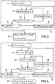
- This procedure 10 comprises estimation of a horizon for each pixel of the seismic image and calculation of accumulation values A(x, y) for each of the pixels.
- a first starting pixel (x, y) is selected in step 11.
- the accumulation takes place in step 12 by incrementing by a unitary value the accumulation value A(x, y).
- a subsequent pixel (x, y) of the current horizon is selected in step 14 before returning to the accumulation step 12.
- the selection is effected in step 14 by choosing a neighboring pixel in a direction of propagation chosen depending on local amplitude variations in the seismic image.
- test 15 determines in test 15 whether all the starting pixels have been taken into account.
- a new starting pixel is taken for the pixel (x, y) in step 16 as long as test 15 is negative, and the procedure returns to step 12 to propagate a horizon from this starting pixel and update the accumulation values of the pixels encountered along this horizon.
- the synthesized image consisting of accumulation values A(x, y) is terminated when test 15 reveals that all the starting pixels have been taken into account.
- the representation is of the same type as in the seismic image, it may also be in two colors (not rendered in the figure), one for negative amplitudes, the other for positive amplitudes, with the pixel intensities corresponding to the absolute value of the seismic amplitudes reallocated to the pixels of the synthesized image.
- the structural enhancement provided to the seismic image of Figure 1 can be seen in Figure 4 .
- the structural information added comes from the synthesized image of Figure 2 , and allows in particular the geological structure in the left part of the seismic image, that with the most noise, to stand out.
- the structural enhancement provides accentuation that makes the interpretation of seismic data easier.
- a geophysicist observing a seismic representation of the kind in Figure 4 is able to proceed with the customary interpretations while benefiting from the structural enhancement.
- Figure 5 illustrates an exemplary embodiment of the method, which can be applied as a variant of Figure 3 to produce a rendering that is both lithological and structural from seismic images.
- the procedure 30 for generating the synthesized image is modified in relation to that 10 of Figure 3 so as to take account of the sign of the seismic amplitudes at the starting pixels.
- This procedure 30 is very close in its execution to that 10 of Figure 3 , the steps designated by the same reference number being identical.
- the scale factor ⁇ corresponds, for example, to a mean thickness of the estimated seismic horizons.
- the method that has just been described is typically implemented in a computer or workstation whose processor executes the above steps under the control of a program, the instructions of which are run by the processor on the seismic images loaded from a storage, e.g. hard drive, memory.
- the seismic images may be processed as indicated in Figure 3 or Figure 5 . It is also possible to generate and then store the synthesized images (or even the seismic horizons) before transforming them to return to a seismic representation.
Landscapes
- Engineering & Computer Science (AREA)
- Remote Sensing (AREA)
- Physics & Mathematics (AREA)
- Life Sciences & Earth Sciences (AREA)
- Acoustics & Sound (AREA)
- Environmental & Geological Engineering (AREA)
- Geology (AREA)
- General Life Sciences & Earth Sciences (AREA)
- General Physics & Mathematics (AREA)
- Geophysics (AREA)
- Image Processing (AREA)
- Geophysics And Detection Of Objects (AREA)
Abstract
Description
- The present invention relates to the analysis of seismic images of the subsurface.
- It is known, especially in oil exploration, to determine the position of oil reservoirs from the results of geophysical measurements carried out from the surface or in well bores. In the technology of reflection seismology technology, these measurements involve emitting a wave into the subsurface and measuring a signal comprising diverse echoes of the wave on geological structures being investigated. These structures are typically surfaces separating distinct materials, faults, etc. Other measurements are carried out from wells. Acoustic waves or electromagnetic radiation are then sent into the subsurface.
- The measurements are processed to recreate a model of the subsurface, generally in the form of seismic images or echographic images. These images may be two-dimensional (seismic sections) or three-dimensional (seismic blocks). A seismic image consists of pixels, the intensity of which represents a seismic amplitude depending on local impedance variations.
- Geophysicists are used to analyzing such seismic images bearing amplitude information. By visual observation they are able to separate subsurface areas having different characteristics with a view to determining the structure of the subsurface.
- Automatic methods exist for extracting structural information from seismic images. In particular, it is known to estimate seismic horizons by computer analysis of the amplitude gradients in the seismic image. The horizons thus estimated are called "synthesized horizons" in contrast with horizons determined by manual checking of the images.
- One possible method for estimating horizons in a two-dimensional seismic image consists in investigating, starting from one pixel of the image, the direction along which the local amplitude gradient is minimal. By propagating in this direction, a line representing a synthesized horizon is gradually constructed. If the seismic image is three-dimensional, it is possible to estimate horizons in the form of surfaces transverse to the vertical direction, for example by means of the propagation method described in French patent No.
2 869 693 - Synthesized horizons may be processed to generate accumulation values (or synthesized accumulation values) forming a synthesized image, having the same dimensions as the seismic image, containing structural information on the organization of the subsurface. The accumulation values are, for example, calculated on a computer as follows. Starting from each pixel of the seismic image, a horizon is estimated by a gradient propagation method and a value of one is allocated to each pixel of this estimated horizon and a value of zero is allocated to all the other pixels. The sum of the values (1 or 0) allocated to each pixel of the synthesized image in relation to the horizons coming from the various pixels of the seismic image yields an accumulation value. High accumulation values correspond in particular to areas of the image where different horizons converge, while low values instead represent areas where the physical characteristics are relatively homogeneous.
- The images formed by the synthesized accumulation values may be transformed in the way described in
US patent No. 6,771,800 to carry out a chrono-stratigraphic analysis of the seismic images. The transformation is nonlinear and calculated by integrating accumulation values along vertical lines. It provides conversion from a physical time scale to a pseudo-geological time scale. The transformed image has connected components that can be interpreted as corresponding to geological deposits, demonstrating geological hiatuses between them. - Synthesized images calculated by accumulation along estimated horizons constitute a sort of summary of the structural information and are therefore very useful for getting an idea of the geometry of the subsurface. The information they visualize is more structural than lithological, as they no longer involve the seismic amplitude values but only their continuities and discontinuities. This limits their interest to geophysicists, who often prefer to examine seismic images themselves, despite the difficulty they might have in distinguishing the structure in these.
- The present document introduces a new type of seismic image processing which reconciles advantages of various modes of representation. Thus a method for processing seismic images of the subsurface is proposed, as set out in the appended claims.
- The synthesized images are reprocessed to return to a mode of representation close to that of the original seismic image. The seismic representation may be seen as a seismic image enhanced by the addition of structural information coming from the synthesized image. This makes reading and interpreting the images easier.
- The synthesized images generated in the method are generally less clear than those obtained by accumulation of always positive quantities. However, their signed amplitudes convey some physical information linked with variations in impedance. The spatial convolution of this synthesized image with a convolution kernel such as a wavelet provides a more realistic representation of seismic amplitudes.
- Another aspect of the invention relates to a computer program for a system for processing seismic images of the subsurface, the program comprising instructions for implementing the steps of a method such as defined above when the program is run by a computer of the seismic image processing system.
- Other particular features and advantages of the present invention will become apparent in the description below of non-limiting exemplary embodiments with reference to the appended drawings, in which:
-
Figure 1 shows an exemplary record of a seismic image; -
Figure 2 shows a form of synthesized image obtained from the seismic image ofFigure 1 ; -
Figure 3 is a flow chart of a seismic image processing method which is not specifically claimed; -
Figure 4 shows a seismic representation structurally enhanced according to the method illustrated byFigure 3 ; -
Figure 5 is a flow chart of an embodiment of the seismic image processing method as proposed herein; -
Figure 6 shows another form of synthesized image used in the method illustrated byFigure 5 ; and -
Figure 7 shows a seismic representation structurally enhanced according to the method illustrated byFigure 5 . - With reference to
Figure 1 , a seismic image is commonly in the form of an array of pixels with intensities corresponding to seismic amplitudes. The representation is generally in two colors (not rendered in the figure), one for negative amplitudes, the other for positive amplitudes. When it is two-dimensional, the image may correspond to a two-dimensional integration of vertical seismic traces. It may also correspond to a vertical section through a seismic block obtained by three-dimensionally integrating vertical seismic traces. - In a manner known per se, such a seismic image may be processed to generate a synthesized image such as that shown in
Figure 2 by accumulation along estimated seismic horizons. The synthesized image is, for example, represented monochromatically with grey shades that are darker the higher the accumulation values of the pixels. In the case ofFigure 2 , these accumulation values are all positive. - The synthesized image shown in
Figure 2 has been derived from the seismic image ofFigure 1 by the conventional method mentioned in the introduction, implemented for example according to the procedure 10 illustrated inFigure 3 . - This procedure 10 comprises estimation of a horizon for each pixel of the seismic image and calculation of accumulation values A(x, y) for each of the pixels. A first starting pixel (x, y) is selected in
step 11. The accumulation takes place instep 12 by incrementing by a unitary value the accumulation value A(x, y). If the current seismic horizon has not been completely covered (test 13), i.e. if the propagation has not yet reached the two lateral edges of the image, a subsequent pixel (x, y) of the current horizon is selected instep 14 before returning to theaccumulation step 12. The selection is effected instep 14 by choosing a neighboring pixel in a direction of propagation chosen depending on local amplitude variations in the seismic image. Whentest 13 reveals that the current seismic horizon has been completely covered, the procedure determines intest 15 whether all the starting pixels have been taken into account. A new starting pixel is taken for the pixel (x, y) instep 16 as long astest 15 is negative, and the procedure returns tostep 12 to propagate a horizon from this starting pixel and update the accumulation values of the pixels encountered along this horizon. The synthesized image consisting of accumulation values A(x, y) is terminated whentest 15 reveals that all the starting pixels have been taken into account. - In the method illustrated in
Figure 3 , in order to allocate signed amplitudes to the pixels of such a synthesized image, it is transformed by combining it with the original seismic image. - In the example illustrated by
Figure 3 , the combination is carried out in the form of a product pixel by pixel:
- The exponents α and β may be adapted to the needs of each particular application. In order to search for oil reservoirs, it has been determined that the values α = 1/2, β = 1 are satisfactory.
-
Figure 4 shows the seismic representation obtained with the exponent values α = 1/2, β = 1 from the synthesized image ofFigure 2 combined with the seismic image ofFigure 1 . As the representation is of the same type as in the seismic image, it may also be in two colors (not rendered in the figure), one for negative amplitudes, the other for positive amplitudes, with the pixel intensities corresponding to the absolute value of the seismic amplitudes reallocated to the pixels of the synthesized image. - The structural enhancement provided to the seismic image of
Figure 1 can be seen inFigure 4 . The structural information added comes from the synthesized image ofFigure 2 , and allows in particular the geological structure in the left part of the seismic image, that with the most noise, to stand out. In the right part too, where the noise is relatively less significant, the structural enhancement provides accentuation that makes the interpretation of seismic data easier. Generally speaking, a geophysicist observing a seismic representation of the kind inFigure 4 is able to proceed with the customary interpretations while benefiting from the structural enhancement. -
Figure 5 illustrates an exemplary embodiment of the method, which can be applied as a variant ofFigure 3 to produce a rendering that is both lithological and structural from seismic images. - The
procedure 30 for generating the synthesized image is modified in relation to that 10 ofFigure 3 so as to take account of the sign of the seismic amplitudes at the starting pixels. Thisprocedure 30 is very close in its execution to that 10 ofFigure 3 , the steps designated by the same reference number being identical. - After selecting the starting pixel for estimating a horizon, in
step step 31 as corresponding to the sign of the starting pixel in the seismic image: δ = +1 if A(x, y) ≥ 0 and δ = -1 if A(x, y) < 0. It is this signed value δ that is added (in step 32, executed after eachstep 31 or 14) to the accumulation values A(x, y) of the pixels encountered along the estimated horizon for the current starting pixel. - The synthesized image which results from this looks as shown in
Figure 6 for the case of the seismic image ofFigure 1 . Here, the representation is, for example, in two colors (not rendered in the figure), one for negative amplitudes, the other for positive amplitudes, with the pixel intensities corresponding to the absolute value of the signed accumulation values. It can be seen that the rendering of the structure is less accentuated than in the example ofFigure 2 . However, a piece of signed information is taken into account and, in order to obtain a rendering of the seismic type (Figure 7 ), the synthesized image is transformed instep 40 by applying to it a spatial convolution with a convolution kernel W(x, y), which is symbolically designated P(x, y) = A(x, y)*W(x, y). - In practice it suffices to carry out the convolution operation along the vertical direction (x):

- The convolution kernel W(x) used in equation (2) may in particular be a wavelet such as, for example, a Ricker wavelet of the form:

- The method that has just been described is typically implemented in a computer or workstation whose processor executes the above steps under the control of a program, the instructions of which are run by the processor on the seismic images loaded from a storage, e.g. hard drive, memory. The seismic images may be processed as indicated in
Figure 3 or Figure 5 . It is also possible to generate and then store the synthesized images (or even the seismic horizons) before transforming them to return to a seismic representation. - Generally speaking, many variants may be applied to the non-limiting embodiments that have been described, without departing from the scope of the invention. In particular, the method is applicable to three-dimensional seismic images.
- Embodiments of the invention are as defined in the following sections A through :
- A. A method of processing seismic images of the subsurface, comprising the steps of:
- analyzing a seismic image to estimate seismic horizons in an area of the subsurface;
- calculating an accumulation value associated with each pixel of the seismic image by accumulation along a set of estimated seismic horizons to form a synthesized image composed of accumulation values; and
- transforming the synthesized image to obtain a seismic representation in which signed amplitudes are allocated to the pixels of the synthesized image.
- B. The method as defined in section A, wherein the step of calculating an accumulation value associated with a pixel of the seismic image comprises accumulating signed quantities respectively associated with horizons of said set passing through said pixel, the signed quantity associated with a horizon depending on the sign of an amplitude of a starting pixel of said horizon in the seismic image.
- C. The method as defined in section B, wherein the signed quantity is equal to +1 if the amplitude of the starting pixel in the seismic image is positive, and -1 if the amplitude of the starting pixel in the seismic image is negative.
- D. The method as defined in section B or C, wherein the step of transforming the synthesized image comprises a spatial convolution (40) of the synthesized image with a convolution kernel.
- E. The method as defined in section D, wherein the spatial convolution is carried out in a vertical direction.
- F. The method as defined in section D or E, wherein the convolution kernel is a wavelet.
- G. The method as defined in section A, wherein the step of transforming the synthesized image comprises combining (20) the synthesized image with the seismic image.
- H. The method as defined in section G, wherein the step of calculating an accumulation value associated with a pixel of the seismic image comprises accumulating unitary values respectively associated with horizons of said set passing through said pixel.
- I. The method as defined in section G or H, wherein the combination (20) of the synthesized image with the seismic image is a product per pixel in the form P(x, y) = A(x, y)α × S(x, y)β, where P(x,y) is the value of a pixel in said seismic representation, A(x, y) is the accumulation value of said pixel in the synthesized image, S(x, y) is the amplitude of said pixel in the seismic image, and α and β are two positive exponents.
- J. The method as defined in section I, wherein α = 1/2 and β = 1.
- K. A computer program for a processing system of seismic images of the subsurface, the program comprising instructions for implementing the steps of a method according to any one of the preceding sections when the program is run by a computer of the seismic image processing system.
Claims (5)
- A method of processing seismic images of the subsurface, the method comprising:- analyzing a seismic image to estimate seismic horizons in an area of the subsurface;- calculating an accumulation value associated with each pixel of the seismic image by accumulation along a set of estimated seismic horizons to form a synthesized image composed of accumulation values; and- transforming the synthesized image to obtain a seismic representation in which signed amplitudes are allocated to the pixels of the synthesized image,characterized in that calculating an accumulation value associated with a pixel of the seismic image comprises accumulating signed quantities respectively associated with horizons of said set passing through said pixel, the signed quantity associated with a horizon depending on the sign of an amplitude of a starting pixel of said horizon in the seismic image, and
wherein transforming the synthesized image comprises a spatial convolution (40) of the synthesized image with a convolution kernel. - The method as claimed in Claim 1, wherein the signed quantity is equal to +1 if the amplitude of the starting pixel in the seismic image is positive, and -1 if the amplitude of the starting pixel in the seismic image is negative.
- The method as claimed in any one of the preceding Claims, wherein the spatial convolution is carried out in a vertical direction.
- The method as claimed in any one of the preceding Claims, wherein the convolution kernel is a wavelet.
- A computer program for a processing system of seismic images of the subsurface, the program comprising instructions for implementing the steps of a method according to any one of the preceding claims when the program is run by a computer of the seismic image processing system.
Applications Claiming Priority (3)
| Application Number | Priority Date | Filing Date | Title |
|---|---|---|---|
| FR0707794A FR2923312B1 (en) | 2007-11-06 | 2007-11-06 | METHOD FOR PROCESSING SEISMIC IMAGES OF THE BASEMENT |
| PCT/EP2008/064893 WO2009059951A2 (en) | 2007-11-06 | 2008-11-03 | Method of processing seismic images of the subsurface |
| EP08847957.1A EP2217948B1 (en) | 2007-11-06 | 2008-11-03 | Method of processing seismic images of the subsurface |
Related Parent Applications (2)
| Application Number | Title | Priority Date | Filing Date |
|---|---|---|---|
| EP08847957.1A Division EP2217948B1 (en) | 2007-11-06 | 2008-11-03 | Method of processing seismic images of the subsurface |
| EP08847957.1A Division-Into EP2217948B1 (en) | 2007-11-06 | 2008-11-03 | Method of processing seismic images of the subsurface |
Publications (2)
| Publication Number | Publication Date |
|---|---|
| EP3470885A1 true EP3470885A1 (en) | 2019-04-17 |
| EP3470885B1 EP3470885B1 (en) | 2020-08-12 |
Family
ID=39581851
Family Applications (2)
| Application Number | Title | Priority Date | Filing Date |
|---|---|---|---|
| EP18206878.3A Active EP3470885B1 (en) | 2007-11-06 | 2008-11-03 | Method of processing seismic images of the subsurface |
| EP08847957.1A Active EP2217948B1 (en) | 2007-11-06 | 2008-11-03 | Method of processing seismic images of the subsurface |
Family Applications After (1)
| Application Number | Title | Priority Date | Filing Date |
|---|---|---|---|
| EP08847957.1A Active EP2217948B1 (en) | 2007-11-06 | 2008-11-03 | Method of processing seismic images of the subsurface |
Country Status (5)
| Country | Link |
|---|---|
| US (1) | US8582826B2 (en) |
| EP (2) | EP3470885B1 (en) |
| JP (1) | JP5579613B2 (en) |
| FR (1) | FR2923312B1 (en) |
| WO (1) | WO2009059951A2 (en) |
Families Citing this family (8)
| Publication number | Priority date | Publication date | Assignee | Title |
|---|---|---|---|---|
| WO2010051332A1 (en) * | 2008-10-31 | 2010-05-06 | Saudi Arabian Oil Company | A seismic image filtering machine to generate a filtered seismic image, program products, and related methods |
| FR2965616B1 (en) * | 2010-10-01 | 2012-10-05 | Total Sa | METHOD OF IMAGING A LONGITUDINAL DRIVE |
| JP6007538B2 (en) * | 2012-03-27 | 2016-10-12 | 日本電気株式会社 | Environmental observation system |
| EP2883087B1 (en) * | 2012-08-08 | 2021-06-23 | Total Se | Method for enhancing the determination of a seismic horizon |
| US10036820B2 (en) | 2016-03-04 | 2018-07-31 | General Electric Company | Expert guided knowledge acquisition system for analyzing seismic data |
| US11016212B2 (en) * | 2017-04-11 | 2021-05-25 | Saudi Arabian Oil Company | Compressing seismic wavefields in three-dimensional reverse time migration |
| US11656378B2 (en) | 2020-06-08 | 2023-05-23 | Saudi Arabian Oil Company | Seismic imaging by visco-acoustic reverse time migration |
| CN112269208B (en) * | 2020-11-04 | 2023-08-01 | 中石化石油工程技术服务有限公司 | Seismic attribute continuous mapping method crossing three-dimensional seismic work area |
Citations (4)
| Publication number | Priority date | Publication date | Assignee | Title |
|---|---|---|---|---|
| US5671136A (en) * | 1995-12-11 | 1997-09-23 | Willhoit, Jr.; Louis E. | Process for seismic imaging measurement and evaluation of three-dimensional subterranean common-impedance objects |
| EP0842443A1 (en) * | 1996-05-31 | 1998-05-20 | Elf Exploration Production | Method for automatically determining stratification beds in a site |
| FR2869693A1 (en) * | 2004-04-30 | 2005-11-04 | Total France Sa | Method of propagating a seismic marker through a set of seismic traces |
| EP1717604A1 (en) * | 2005-04-29 | 2006-11-02 | Institut Français du Pétrole | Sedimentological interpretation method by estimating different chronological scenarios for the laying down of sedimentary layers |
Family Cites Families (7)
| Publication number | Priority date | Publication date | Assignee | Title |
|---|---|---|---|---|
| FR2635197B1 (en) * | 1988-08-05 | 1990-09-28 | Inst Francais Du Petrole | METHOD FOR OBTAINING A REPRESENTATIVE MODEL OF A HETEROGENEOUS MEDIUM AND IN PARTICULAR OF THE BASEMENT |
| FR2738920B1 (en) | 1995-09-19 | 1997-11-14 | Elf Aquitaine | METHOD FOR AUTOMATIC SEISMIC FACIAL RECOGNITION |
| US6138075A (en) * | 1998-08-05 | 2000-10-24 | Landmark Graphics Corporation | Methods and apparatus for analyzing seismic data |
| FR2808336B1 (en) * | 2000-04-26 | 2002-06-07 | Elf Exploration Prod | METHOD OF CHRONO-STRATIGRAPHIC INTERPRETATION OF A SEISMIC SECTION OR BLOCK |
| FR2841343B1 (en) * | 2002-06-19 | 2005-05-27 | Tsurf | DEVICE AND PROGRAM PRODUCT FOR EXTRACTING A GEOLOGICAL HORIZON AND ASSOCIATED PROPERTIES |
| CN101583911B (en) * | 2006-09-01 | 2013-01-02 | 哈利伯顿兰德马克绘图公司 | Systems and methods for imaging a wave body |
| AU2008322505B9 (en) * | 2007-11-14 | 2014-10-02 | Cgg Jason (Netherlands) B.V. | Seismic data processing |
-
2007
- 2007-11-06 FR FR0707794A patent/FR2923312B1/en not_active Expired - Fee Related
-
2008
- 2008-11-03 WO PCT/EP2008/064893 patent/WO2009059951A2/en not_active Ceased
- 2008-11-03 US US12/741,238 patent/US8582826B2/en active Active
- 2008-11-03 EP EP18206878.3A patent/EP3470885B1/en active Active
- 2008-11-03 EP EP08847957.1A patent/EP2217948B1/en active Active
- 2008-11-03 JP JP2010531541A patent/JP5579613B2/en not_active Expired - Fee Related
Patent Citations (4)
| Publication number | Priority date | Publication date | Assignee | Title |
|---|---|---|---|---|
| US5671136A (en) * | 1995-12-11 | 1997-09-23 | Willhoit, Jr.; Louis E. | Process for seismic imaging measurement and evaluation of three-dimensional subterranean common-impedance objects |
| EP0842443A1 (en) * | 1996-05-31 | 1998-05-20 | Elf Exploration Production | Method for automatically determining stratification beds in a site |
| FR2869693A1 (en) * | 2004-04-30 | 2005-11-04 | Total France Sa | Method of propagating a seismic marker through a set of seismic traces |
| EP1717604A1 (en) * | 2005-04-29 | 2006-11-02 | Institut Français du Pétrole | Sedimentological interpretation method by estimating different chronological scenarios for the laying down of sedimentary layers |
Non-Patent Citations (3)
| Title |
|---|
| ADMASU F ET AL: "Autotracking of faults on 3D seismic data", GEOPHYSICS SOC. EXPLORATION GEOPHYSICISTS USA, vol. 71, no. 6, November 2006 (2006-11-01), pages A49 - A53, XP002488382, ISSN: 0016-8033 * |
| FARAKLIOTI M ET AL: "Horizon picking in 3D seismic data volumes", MACHINE VISION AND APPLICATIONS SPRINGER-VERLAG GERMANY, vol. 15, no. 4, October 2004 (2004-10-01), pages 216 - 219, XP002488381, ISSN: 0932-8092 * |
| FAUCON T ET AL: "Application of surface topological segmentation to seismic imaging", DISCRETE GEOMETRY FOR COMPUTER IMAGERY. 13TH INTERNATIONAL CONFERENCE, DGCI 2006. PROCEEDINGS (LECTURE NOTES IN COMPUTER SCIENCE VOL.4245) SPRINGER BERLIN, GERMANY, 2006, pages 506 - 517, XP002488822, ISBN: 3-540-47651-2 * |
Also Published As
| Publication number | Publication date |
|---|---|
| JP2011503533A (en) | 2011-01-27 |
| EP2217948A2 (en) | 2010-08-18 |
| FR2923312A1 (en) | 2009-05-08 |
| EP3470885B1 (en) | 2020-08-12 |
| FR2923312B1 (en) | 2009-12-18 |
| WO2009059951A2 (en) | 2009-05-14 |
| WO2009059951A3 (en) | 2009-07-23 |
| EP2217948B1 (en) | 2019-05-08 |
| US20100232651A1 (en) | 2010-09-16 |
| JP5579613B2 (en) | 2014-08-27 |
| US8582826B2 (en) | 2013-11-12 |
Similar Documents
| Publication | Publication Date | Title |
|---|---|---|
| EP3470885B1 (en) | Method of processing seismic images of the subsurface | |
| US6594585B1 (en) | Method of frequency domain seismic attribute generation | |
| US11428834B2 (en) | Processes and systems for generating a high-resolution velocity model of a subterranean formation using iterative full-waveform inversion | |
| US7082368B2 (en) | Seismic event correlation and Vp-Vs estimation | |
| CN102121997B (en) | Method and apparatus for the complete bandwidth source deghosting of marine seismic streamer data | |
| CN102062874B (en) | Complete bandwidth for marine seismic streamer data disappears the method for phantom | |
| US7197399B2 (en) | Method of multiple attenuation | |
| US20130003500A1 (en) | Seismic Data Processing | |
| EP2781935A2 (en) | A system and method for modelling three dimensional shallow water multiples using predictive sea floor reconstruction | |
| EP3211594B1 (en) | Seismic modeling system providing seismic survey data inpainting based upon suspect region boundary comparisons and related methods | |
| EP3436849B1 (en) | Determining displacement between seismic images using optical flow | |
| EP3436850B1 (en) | Determining displacement between seismic images using optical flow | |
| JP2011503533A5 (en) | ||
| EP3217354B1 (en) | Seismic modeling system providing seismic survey data frequency domain inpainting and related methods | |
| Herman et al. | Predictive removal of scattered noise | |
| US6662111B2 (en) | Method for analyzing reflection curvature in seismic data volumes | |
| Ashtari | Automating fault detection in seismic data: integrating image processing with deep learning | |
| WO2024194150A1 (en) | Determining angle gathers from inversion of velocity and reflectivity of a subterranean formation | |
| EP4680997A1 (en) | Determining angle gathers from inversion of velocity and reflectivity of a subterranean formation | |
| EP4281814B1 (en) | Method and system for processing seismic images to obtain a frequency-domain representation of a geological formation | |
| EP4281815B1 (en) | Method and system for processing seismic images to progressively enhance an rgt image of a geological formation | |
| WO2023194763A1 (en) | Method and system for detecting a geological object in a seismic 3d image by using image segmentation | |
| Singh et al. | Enhancing seismic feature orientations: A novel approach using directional derivatives and Hilbert transform of gradient structure tensor | |
| Day et al. | Defect Imaging With Frequency Domain Least-Squares Reverse Time Migration Using Analytical Green’s Functions | |
| Farkhutdinov et al. | Development of deep learning method for automatic seismic first break picking |
Legal Events
| Date | Code | Title | Description |
|---|---|---|---|
| PUAI | Public reference made under article 153(3) epc to a published international application that has entered the european phase |
Free format text: ORIGINAL CODE: 0009012 |
|
| STAA | Information on the status of an ep patent application or granted ep patent |
Free format text: STATUS: THE APPLICATION HAS BEEN PUBLISHED |
|
| AC | Divisional application: reference to earlier application |
Ref document number: 2217948 Country of ref document: EP Kind code of ref document: P |
|
| AK | Designated contracting states |
Kind code of ref document: A1 Designated state(s): AT BE BG CH CY CZ DE DK EE ES FI FR GB GR HR HU IE IS IT LI LT LU LV MC MT NL NO PL PT RO SE SI SK TR |
|
| AX | Request for extension of the european patent |
Extension state: AL BA MK RS |
|
| STAA | Information on the status of an ep patent application or granted ep patent |
Free format text: STATUS: REQUEST FOR EXAMINATION WAS MADE |
|
| 17P | Request for examination filed |
Effective date: 20191015 |
|
| RBV | Designated contracting states (corrected) |
Designated state(s): AT BE BG CH CY CZ DE DK EE ES FI FR GB GR HR HU IE IS IT LI LT LU LV MC MT NL NO PL PT RO SE SI SK TR |
|
| GRAP | Despatch of communication of intention to grant a patent |
Free format text: ORIGINAL CODE: EPIDOSNIGR1 |
|
| STAA | Information on the status of an ep patent application or granted ep patent |
Free format text: STATUS: GRANT OF PATENT IS INTENDED |
|
| INTG | Intention to grant announced |
Effective date: 20200305 |
|
| GRAS | Grant fee paid |
Free format text: ORIGINAL CODE: EPIDOSNIGR3 |
|
| GRAA | (expected) grant |
Free format text: ORIGINAL CODE: 0009210 |
|
| STAA | Information on the status of an ep patent application or granted ep patent |
Free format text: STATUS: THE PATENT HAS BEEN GRANTED |
|
| AC | Divisional application: reference to earlier application |
Ref document number: 2217948 Country of ref document: EP Kind code of ref document: P |
|
| AK | Designated contracting states |
Kind code of ref document: B1 Designated state(s): AT BE BG CH CY CZ DE DK EE ES FI FR GB GR HR HU IE IS IT LI LT LU LV MC MT NL NO PL PT RO SE SI SK TR |
|
| REG | Reference to a national code |
Ref country code: CH Ref legal event code: EP |
|
| REG | Reference to a national code |
Ref country code: IE Ref legal event code: FG4D |
|
| REG | Reference to a national code |
Ref country code: DE Ref legal event code: R096 Ref document number: 602008063150 Country of ref document: DE |
|
| REG | Reference to a national code |
Ref country code: AT Ref legal event code: REF Ref document number: 1302107 Country of ref document: AT Kind code of ref document: T Effective date: 20200915 |
|
| RAP2 | Party data changed (patent owner data changed or rights of a patent transferred) |
Owner name: TOTAL SE |
|
| REG | Reference to a national code |
Ref country code: NL Ref legal event code: FP Ref country code: NL Ref legal event code: PD Owner name: TOTAL SE; FR Free format text: DETAILS ASSIGNMENT: CHANGE OF OWNER(S), CHANGE OF LEGAL ENTITY; FORMER OWNER NAME: TOTAL SA Effective date: 20201103 |
|
| REG | Reference to a national code |
Ref country code: LT Ref legal event code: MG4D |
|
| REG | Reference to a national code |
Ref country code: NO Ref legal event code: T2 Effective date: 20200812 |
|
| PG25 | Lapsed in a contracting state [announced via postgrant information from national office to epo] |
Ref country code: SE Free format text: LAPSE BECAUSE OF FAILURE TO SUBMIT A TRANSLATION OF THE DESCRIPTION OR TO PAY THE FEE WITHIN THE PRESCRIBED TIME-LIMIT Effective date: 20200812 Ref country code: GR Free format text: LAPSE BECAUSE OF FAILURE TO SUBMIT A TRANSLATION OF THE DESCRIPTION OR TO PAY THE FEE WITHIN THE PRESCRIBED TIME-LIMIT Effective date: 20201113 Ref country code: HR Free format text: LAPSE BECAUSE OF FAILURE TO SUBMIT A TRANSLATION OF THE DESCRIPTION OR TO PAY THE FEE WITHIN THE PRESCRIBED TIME-LIMIT Effective date: 20200812 Ref country code: FI Free format text: LAPSE BECAUSE OF FAILURE TO SUBMIT A TRANSLATION OF THE DESCRIPTION OR TO PAY THE FEE WITHIN THE PRESCRIBED TIME-LIMIT Effective date: 20200812 Ref country code: LT Free format text: LAPSE BECAUSE OF FAILURE TO SUBMIT A TRANSLATION OF THE DESCRIPTION OR TO PAY THE FEE WITHIN THE PRESCRIBED TIME-LIMIT Effective date: 20200812 Ref country code: BG Free format text: LAPSE BECAUSE OF FAILURE TO SUBMIT A TRANSLATION OF THE DESCRIPTION OR TO PAY THE FEE WITHIN THE PRESCRIBED TIME-LIMIT Effective date: 20201112 |
|
| REG | Reference to a national code |
Ref country code: AT Ref legal event code: MK05 Ref document number: 1302107 Country of ref document: AT Kind code of ref document: T Effective date: 20200812 |
|
| PG25 | Lapsed in a contracting state [announced via postgrant information from national office to epo] |
Ref country code: LV Free format text: LAPSE BECAUSE OF FAILURE TO SUBMIT A TRANSLATION OF THE DESCRIPTION OR TO PAY THE FEE WITHIN THE PRESCRIBED TIME-LIMIT Effective date: 20200812 Ref country code: PL Free format text: LAPSE BECAUSE OF FAILURE TO SUBMIT A TRANSLATION OF THE DESCRIPTION OR TO PAY THE FEE WITHIN THE PRESCRIBED TIME-LIMIT Effective date: 20200812 Ref country code: IS Free format text: LAPSE BECAUSE OF FAILURE TO SUBMIT A TRANSLATION OF THE DESCRIPTION OR TO PAY THE FEE WITHIN THE PRESCRIBED TIME-LIMIT Effective date: 20201212 |
|
| PG25 | Lapsed in a contracting state [announced via postgrant information from national office to epo] |
Ref country code: DK Free format text: LAPSE BECAUSE OF FAILURE TO SUBMIT A TRANSLATION OF THE DESCRIPTION OR TO PAY THE FEE WITHIN THE PRESCRIBED TIME-LIMIT Effective date: 20200812 Ref country code: CZ Free format text: LAPSE BECAUSE OF FAILURE TO SUBMIT A TRANSLATION OF THE DESCRIPTION OR TO PAY THE FEE WITHIN THE PRESCRIBED TIME-LIMIT Effective date: 20200812 Ref country code: RO Free format text: LAPSE BECAUSE OF FAILURE TO SUBMIT A TRANSLATION OF THE DESCRIPTION OR TO PAY THE FEE WITHIN THE PRESCRIBED TIME-LIMIT Effective date: 20200812 Ref country code: EE Free format text: LAPSE BECAUSE OF FAILURE TO SUBMIT A TRANSLATION OF THE DESCRIPTION OR TO PAY THE FEE WITHIN THE PRESCRIBED TIME-LIMIT Effective date: 20200812 |
|
| REG | Reference to a national code |
Ref country code: DE Ref legal event code: R097 Ref document number: 602008063150 Country of ref document: DE |
|
| PG25 | Lapsed in a contracting state [announced via postgrant information from national office to epo] |
Ref country code: AT Free format text: LAPSE BECAUSE OF FAILURE TO SUBMIT A TRANSLATION OF THE DESCRIPTION OR TO PAY THE FEE WITHIN THE PRESCRIBED TIME-LIMIT Effective date: 20200812 Ref country code: ES Free format text: LAPSE BECAUSE OF FAILURE TO SUBMIT A TRANSLATION OF THE DESCRIPTION OR TO PAY THE FEE WITHIN THE PRESCRIBED TIME-LIMIT Effective date: 20200812 |
|
| REG | Reference to a national code |
Ref country code: DE Ref legal event code: R119 Ref document number: 602008063150 Country of ref document: DE |
|
| PLBE | No opposition filed within time limit |
Free format text: ORIGINAL CODE: 0009261 |
|
| STAA | Information on the status of an ep patent application or granted ep patent |
Free format text: STATUS: NO OPPOSITION FILED WITHIN TIME LIMIT |
|
| PG25 | Lapsed in a contracting state [announced via postgrant information from national office to epo] |
Ref country code: MC Free format text: LAPSE BECAUSE OF FAILURE TO SUBMIT A TRANSLATION OF THE DESCRIPTION OR TO PAY THE FEE WITHIN THE PRESCRIBED TIME-LIMIT Effective date: 20200812 Ref country code: SK Free format text: LAPSE BECAUSE OF FAILURE TO SUBMIT A TRANSLATION OF THE DESCRIPTION OR TO PAY THE FEE WITHIN THE PRESCRIBED TIME-LIMIT Effective date: 20200812 |
|
| REG | Reference to a national code |
Ref country code: CH Ref legal event code: PL |
|
| 26N | No opposition filed |
Effective date: 20210514 |
|
| PG25 | Lapsed in a contracting state [announced via postgrant information from national office to epo] |
Ref country code: IT Free format text: LAPSE BECAUSE OF FAILURE TO SUBMIT A TRANSLATION OF THE DESCRIPTION OR TO PAY THE FEE WITHIN THE PRESCRIBED TIME-LIMIT Effective date: 20200812 Ref country code: LU Free format text: LAPSE BECAUSE OF NON-PAYMENT OF DUE FEES Effective date: 20201103 |
|
| REG | Reference to a national code |
Ref country code: BE Ref legal event code: MM Effective date: 20201130 |
|
| PG25 | Lapsed in a contracting state [announced via postgrant information from national office to epo] |
Ref country code: CH Free format text: LAPSE BECAUSE OF NON-PAYMENT OF DUE FEES Effective date: 20201130 Ref country code: LI Free format text: LAPSE BECAUSE OF NON-PAYMENT OF DUE FEES Effective date: 20201130 Ref country code: SI Free format text: LAPSE BECAUSE OF FAILURE TO SUBMIT A TRANSLATION OF THE DESCRIPTION OR TO PAY THE FEE WITHIN THE PRESCRIBED TIME-LIMIT Effective date: 20200812 |
|
| PG25 | Lapsed in a contracting state [announced via postgrant information from national office to epo] |
Ref country code: IE Free format text: LAPSE BECAUSE OF NON-PAYMENT OF DUE FEES Effective date: 20201103 |
|
| PG25 | Lapsed in a contracting state [announced via postgrant information from national office to epo] |
Ref country code: DE Free format text: LAPSE BECAUSE OF NON-PAYMENT OF DUE FEES Effective date: 20210601 |
|
| PG25 | Lapsed in a contracting state [announced via postgrant information from national office to epo] |
Ref country code: TR Free format text: LAPSE BECAUSE OF FAILURE TO SUBMIT A TRANSLATION OF THE DESCRIPTION OR TO PAY THE FEE WITHIN THE PRESCRIBED TIME-LIMIT Effective date: 20200812 Ref country code: MT Free format text: LAPSE BECAUSE OF FAILURE TO SUBMIT A TRANSLATION OF THE DESCRIPTION OR TO PAY THE FEE WITHIN THE PRESCRIBED TIME-LIMIT Effective date: 20200812 Ref country code: CY Free format text: LAPSE BECAUSE OF FAILURE TO SUBMIT A TRANSLATION OF THE DESCRIPTION OR TO PAY THE FEE WITHIN THE PRESCRIBED TIME-LIMIT Effective date: 20200812 |
|
| PG25 | Lapsed in a contracting state [announced via postgrant information from national office to epo] |
Ref country code: PT Free format text: LAPSE BECAUSE OF FAILURE TO SUBMIT A TRANSLATION OF THE DESCRIPTION OR TO PAY THE FEE WITHIN THE PRESCRIBED TIME-LIMIT Effective date: 20200812 Ref country code: BE Free format text: LAPSE BECAUSE OF NON-PAYMENT OF DUE FEES Effective date: 20201130 |
|
| P01 | Opt-out of the competence of the unified patent court (upc) registered |
Effective date: 20230524 |
|
| REG | Reference to a national code |
Ref country code: GB Ref legal event code: 732E Free format text: REGISTERED BETWEEN 20240523 AND 20240529 |
|
| REG | Reference to a national code |
Ref country code: NL Ref legal event code: PD Owner name: TOTALENERGIES ONETECH; FR Free format text: DETAILS ASSIGNMENT: CHANGE OF OWNER(S), ASSIGNMENT; FORMER OWNER NAME: TOTAL SA Effective date: 20240905 Ref country code: NL Ref legal event code: HC Owner name: TOTALENERGIES SE; FR Free format text: DETAILS ASSIGNMENT: CHANGE OF OWNER(S), CHANGE OF OWNER(S) NAME; FORMER OWNER NAME: TOTAL SE Effective date: 20240905 |
|
| PGFP | Annual fee paid to national office [announced via postgrant information from national office to epo] |
Ref country code: NL Payment date: 20251119 Year of fee payment: 18 |
|
| PGFP | Annual fee paid to national office [announced via postgrant information from national office to epo] |
Ref country code: GB Payment date: 20251121 Year of fee payment: 18 |
|
| PGFP | Annual fee paid to national office [announced via postgrant information from national office to epo] |
Ref country code: NO Payment date: 20251125 Year of fee payment: 18 |
|
| PGFP | Annual fee paid to national office [announced via postgrant information from national office to epo] |
Ref country code: FR Payment date: 20251126 Year of fee payment: 18 |