EP3470877A1 - Hard target detection for optical systems - Google Patents
Hard target detection for optical systems Download PDFInfo
- Publication number
- EP3470877A1 EP3470877A1 EP18199867.5A EP18199867A EP3470877A1 EP 3470877 A1 EP3470877 A1 EP 3470877A1 EP 18199867 A EP18199867 A EP 18199867A EP 3470877 A1 EP3470877 A1 EP 3470877A1
- Authority
- EP
- European Patent Office
- Prior art keywords
- laser
- hard target
- laser beam
- transmitter
- retroreflections
- Prior art date
- Legal status (The legal status is an assumption and is not a legal conclusion. Google has not performed a legal analysis and makes no representation as to the accuracy of the status listed.)
- Granted
Links
Images


Classifications
-
- H—ELECTRICITY
- H01—ELECTRIC ELEMENTS
- H01S—DEVICES USING THE PROCESS OF LIGHT AMPLIFICATION BY STIMULATED EMISSION OF RADIATION [LASER] TO AMPLIFY OR GENERATE LIGHT; DEVICES USING STIMULATED EMISSION OF ELECTROMAGNETIC RADIATION IN WAVE RANGES OTHER THAN OPTICAL
- H01S3/00—Lasers, i.e. devices using stimulated emission of electromagnetic radiation in the infrared, visible or ultraviolet wave range
- H01S3/0014—Monitoring arrangements not otherwise provided for
-
- G—PHYSICS
- G01—MEASURING; TESTING
- G01S—RADIO DIRECTION-FINDING; RADIO NAVIGATION; DETERMINING DISTANCE OR VELOCITY BY USE OF RADIO WAVES; LOCATING OR PRESENCE-DETECTING BY USE OF THE REFLECTION OR RERADIATION OF RADIO WAVES; ANALOGOUS ARRANGEMENTS USING OTHER WAVES
- G01S17/00—Systems using the reflection or reradiation of electromagnetic waves other than radio waves, e.g. lidar systems
- G01S17/02—Systems using the reflection of electromagnetic waves other than radio waves
- G01S17/04—Systems determining the presence of a target
-
- G—PHYSICS
- G01—MEASURING; TESTING
- G01S—RADIO DIRECTION-FINDING; RADIO NAVIGATION; DETERMINING DISTANCE OR VELOCITY BY USE OF RADIO WAVES; LOCATING OR PRESENCE-DETECTING BY USE OF THE REFLECTION OR RERADIATION OF RADIO WAVES; ANALOGOUS ARRANGEMENTS USING OTHER WAVES
- G01S17/00—Systems using the reflection or reradiation of electromagnetic waves other than radio waves, e.g. lidar systems
- G01S17/02—Systems using the reflection of electromagnetic waves other than radio waves
- G01S17/06—Systems determining position data of a target
- G01S17/08—Systems determining position data of a target for measuring distance only
-
- G—PHYSICS
- G01—MEASURING; TESTING
- G01S—RADIO DIRECTION-FINDING; RADIO NAVIGATION; DETERMINING DISTANCE OR VELOCITY BY USE OF RADIO WAVES; LOCATING OR PRESENCE-DETECTING BY USE OF THE REFLECTION OR RERADIATION OF RADIO WAVES; ANALOGOUS ARRANGEMENTS USING OTHER WAVES
- G01S7/00—Details of systems according to groups G01S13/00, G01S15/00, G01S17/00
- G01S7/48—Details of systems according to groups G01S13/00, G01S15/00, G01S17/00 of systems according to group G01S17/00
- G01S7/481—Constructional features, e.g. arrangements of optical elements
-
- G—PHYSICS
- G01—MEASURING; TESTING
- G01S—RADIO DIRECTION-FINDING; RADIO NAVIGATION; DETERMINING DISTANCE OR VELOCITY BY USE OF RADIO WAVES; LOCATING OR PRESENCE-DETECTING BY USE OF THE REFLECTION OR RERADIATION OF RADIO WAVES; ANALOGOUS ARRANGEMENTS USING OTHER WAVES
- G01S7/00—Details of systems according to groups G01S13/00, G01S15/00, G01S17/00
- G01S7/48—Details of systems according to groups G01S13/00, G01S15/00, G01S17/00 of systems according to group G01S17/00
- G01S7/481—Constructional features, e.g. arrangements of optical elements
- G01S7/4818—Constructional features, e.g. arrangements of optical elements using optical fibres
-
- G—PHYSICS
- G01—MEASURING; TESTING
- G01S—RADIO DIRECTION-FINDING; RADIO NAVIGATION; DETERMINING DISTANCE OR VELOCITY BY USE OF RADIO WAVES; LOCATING OR PRESENCE-DETECTING BY USE OF THE REFLECTION OR RERADIATION OF RADIO WAVES; ANALOGOUS ARRANGEMENTS USING OTHER WAVES
- G01S7/00—Details of systems according to groups G01S13/00, G01S15/00, G01S17/00
- G01S7/48—Details of systems according to groups G01S13/00, G01S15/00, G01S17/00 of systems according to group G01S17/00
- G01S7/483—Details of pulse systems
- G01S7/484—Transmitters
Definitions
- the present invention relates generally to optical systems, and in particular to remote sensing systems such as light detection and ranging (lidar) systems.
- Remote sensing systems which may be implemented onboard aircraft, for example, are configured to inject light into an area of interest in order to monitor the environment within that area of interest. Because humans may enter the area of interest, eye safety must be ensured.
- eye safety has been handled using multiple methods.
- the optical system may limit the projected wavelengths to eye safe wavelengths, such as wavelengths that fall outside of the range between 400 nm and 1400 nm.
- Optical systems may also utilize low power levels, and/or restrict access to the area of interest. While these methods may be effective at ensuring eye safety, they may not be practical for all applications. It is desirable to provide eye safety for optical systems that are unable to utilize these safety methods.
- a hard target detection system for a free-space laser system includes a laser, an optical detector, and electronics.
- the laser is configured to emit a laser beam along an optical path through transmitter optics into a field of view.
- the optical detector is positioned along a laser transmitter path and configured to receive retroreflections of the laser beam.
- the electronics are configured to determine if an output of the optical detector is indicative of presence of a hard target within the field of view, and control the laser to a safe state if the output is indicative of presence of the hard target.
- a method of detecting hard targets in a free-space laser system includes emitting a laser beam along an optical path to transmitter optics; directing, by the transmitter optics, the beam into a field of view along a laser transmitter path; receiving, by an optical detector positioned along the laser transmitter path, retroreflections of the laser beam; detecting a hard target within the field of view based on the retroreflections; and controlling the laser to a safe state if the hard target is detected within the field of view.
- Hard target detection for a free-space laser system is disclosed herein that controls an operational state of a laser upon detection of a hard target within a field of view of the laser transmitter.
- the free-space laser system may be a remote sensing system, for example, or other optical system.
- the remote sensing system includes, among other things, a laser, transmitter and receiver optics, and control electronics.
- the laser emits a laser beam along an optical path, through transmitter optics, and into an area of interest, such as the atmosphere external to an aircraft. This area of interest may become occupied by a person or other hard target. If the emitted laser is above eye-safe levels, it is desirable to control the laser into a safe state upon detection of a hard target within the field of view of the transmitted laser beam.
- An optical detector is positioned along the laser transmitter path to receive retroreflections of the laser beam.
- the retroreflections may be directed to the optical detector using a tap or other method, for example.
- the retroreflections may be monitored to determine if a hard object has entered the field of view of the laser transmitter. For example, if the amplitude of the retroreflection is greater than a threshold, the laser may be turned off, or controlled to a reduced, eye-safe intensity.
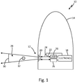
- FIG. 1 is a diagram illustrating system 10 that includes optical system 12 implemented onboard aircraft 14.
- Optical system 12 may be an optical sensor, for example, configured to emit one or more laser beams into the atmosphere external to aircraft 14.
- Optical system 12 may be any aircraft sensor or other free-space laser system configured to emit light external to aircraft 14 to determine a condition.
- optical system 12 may be a light detection and ranging (lidar) system configured to determine, among other conditions, air, ice, and/or smoke conditions based on backscatter of the emitted laser beam. While illustrated as onboard aircraft 14, optical system 12 may be implemented in any location and is not limited to use onboard a vehicle.
- Optical system 12 includes laser 16, system electronics 18, transmitter and receiver optics 20, optical path 22, optical detector 24, and detector elements 26.
- Laser 16 is configured to emit a laser beam along optical path 22 to transmitter and receiver optics 20.
- Transmitter optics direct the laser beam into an area of interest external to aircraft 14.
- Receiver optics are configured to receive backscatter, for example, from particles, molecules, and/or any other physical substance within the area of interest.
- the received backscatter is directed to detector elements 26 which convert the received backscatter into electrical signals for analysis.
- the electrical signals may be analyzed by system electronics 18 to determine conditions within the desired volume of field of view 28.
- Detector elements 26 may be photo-diodes, photon counters, focal plane arrays, or any other photo sensitive devices.
- Optical path 22 may include any optical elements configured to direct the emitted laser to the transmitter optics such as, for example, fiber optic cables, lenses, or any other optics.
- System electronics 18 may include one or more controllers, processors, application specific integrated circuits (ASICS), or any other analog or digital circuitry.
- optical system 12 includes field of view 28 and nominal ocular hazard distance (NOHD) 30.
- Optical system 12 may require the use of emitted laser energy above eye safe levels within field of view 28, for example. Eye safety levels may be defined by the United States Food and Drug Administration (FDA) in 21 CFR 1040.10 and 21 CFR 1040.11, for example, or by other regulatory entities.
- NOHD 30 is the distance from the laser exit aperture up to which the laser beam intensity emitted by optical system 12 is at or above eye safe intensity.
- the eye safe state may be off, or may be a reduced intensity such that the beam intensity emitted by laser 16 is below eye safe levels for a person at the location of hard target 32.
- Transmitter and receiver optics 20 are configured, for example, to direct the laser beam into the area of interest, and collect backscatter of the laser beam for analysis.
- Transmitter and receiver optics 20 may include separate optical elements for laser transmission and backscatter collection. Theses separate optical elements may be oriented about separate optical axes.
- FIG. 2 illustrates an embodiment of a bi-static system that includes transmitter and receiver optics 20.
- transmitter and receiver optics 20 include transmitter telescope 40 and receiver telescope 42.
- Field of view 28 is the field of view for a laser beam directed by transmitter telescope 40.
- Receiver telescope 42 has a field of view 44.
- receiver telescope 42 is configured to collect backscatter of the laser beam directed by transmitter telescope 40 from particles, molecules, and/or other physical substances within desired volume 46, which is the overlap between field of view 28 and field of view 44.
- optical system 12 may be an air data sensor configured to receive backscatter off of molecules within desired volume 46 and analyze the backscatter to determine conditions of the atmosphere external to aircraft 14. Because receiver telescope 42 has a different field of view than transmitter telescope 40, hard target 32 can enter field of view 28 and not be detected by optical system 12. Thus, it may not be desirable to utilize light captured by receiver telescope 42 to identify a hard target within field of view 28.
- optical detector 24 may be positioned along the laser transmitter path to detect a hard target 32 anywhere within field of view 28.
- the laser transmitter path may be the optical axis of the transmitter optics.
- Optical detector 24 may be positioned to receive retroreflections of the laser beam directed by transmitter telescope 40 into field of view 28, for example. Retroreflections may be, for example, light that reflects from hard target 32 directly back to transmitter telescope 40.
- Optical detector 24 may be a photo-diode, for example, or any other device capable of converting an optical signal into an electronic signal. Retroreflections may be directed from the laser transmitter path to optical detector 24 using an optical tap or other method, for example.
- the output of optical detector 24 may be analyzed to determine if hard target 32 has entered field of view 28.
- the amplitude of the retroreflections may be compared to a threshold.
- the threshold may be any value that corresponds to an amplitude of the retroreflections that indicate presence of hard target 32 within field of view 28.
- Testing may be performed specific to the implementation of optical system 12 to determine the threshold based upon, for example, the intensity of the emitted laser, the optics of system 12, and other properties specific to optical system 12.
- the comparison may be performed by system electronics 18 or any other electronics.
- an analog output of detector 24 may be provided as input to a comparator.
- the other input to the comparator may be an analog signal indicative of the threshold, such that the output of the comparator indicates the presence of hard target 32.
- This output may be directly used as a shutoff signal for laser 16, for example.
- the output of detector 24 may be converted to a digital signal and provided to a controller or other digital logic circuit of electronics 18. Electronics 18 may then execute an algorithm using the digital value from detector 24 to detect hard target 32.
- FIG. 3 illustrates an embodiment of optical system 12 that includes tap 50 positioned along optical path 22.
- Tap 50 may be configured to direct a portion of the emitted laser to laser monitor 52.
- Laser monitor 52 may be configured, for example, to monitor the beam emitted by laser 16 to ensure proper functionality of laser 16.
- Tap 50 may be a beam splitter, fiber coupler, or any other optical device capable of directing a portion of the laser beam from optical path 22 to laser monitor 52. Retroreflections of the laser beam will travel back through transmitter optics 40 to tap 50. The optical properties of tap 50 will direct a portion of the retroreflections in the opposite direction of laser monitor 52.
- detector 24 may be positioned at an output of tap 50 opposite the laser monitor 52 to receive a portion of the retroreflections received through transmitter optics 40.
- optical detector 24 may be utilized to monitor the retroreflections on the laser transmitter path.
- the embodiment in FIG. 3 may also be utilized in a pulsed laser system to determine a distance to hard target 32.
- laser 16 may be a pulsed laser.
- Laser monitor 52 may be utilized to determine when a pulse is emitted by laser 16.
- System electronics 18 may record the pulse time observed by laser monitor 52, for example.
- Optical detector 24 may then receive reflections of the pulse from the hard target 32. The timing of the received reflection may then be compared by electronics 18 to the timing of the laser pulse to determine a travel time of the pulse. The travel time of the pulse may then be utilized to determine a distance to hard target 32. Knowing NOHD 30 for optical system 12, electronics 18 can compare the distance to hard target 32 with NOHD 30. If hard target 32 is outside of NOHD 30, laser 16 may continue to operate at the present intensity.
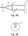
- FIGS. 4a and 4b illustrate an example embodiment of an optical detector 24'.
- transmitter optics include optics 54 and fiber 58.
- Optical detector 24' includes a fiber that is positioned adjacent to transmitter fiber 58.
- the fiber of optical detector 24' may be configured to direct received light to a detector element such as a photo-diode or other optical detector element, for example.
- a beam is focused and directed into field of view 28 by transmitter fiber 58 and optics 54.
- Hard target 32 which may be a person that has entered field of view 28, reflects the beam back toward transmitter optics 54.
- Hard target 32 which may be a person, will be slightly diffuse which will increase the angular width of the reflections over the width of the directed beam.
- the reflections 56 which pass back through transmitter optics 54, are received by the fiber of optical detector 24' and directed to a detector element (not shown).
- the diffuse reflection area 56 surrounds both transmitter fiber 58 and the fiber of optical detector 24'. As hard target 32 moves further away from transmitter optics 54, the reflection area 56 decreases in diameter. Thus, when hard target 32 moves far enough away from optics 54, the fiber of detector 24' may not receive the reflected light to detect hard target 32. However, the system may be configured, for example, such that the reflection area 56 remains large enough that the fiber of detector 24' will receive the retroreflections from hard target 32 for at least as long as hard target 32 remains within NOHD 30 ( FIG. 1 ). If hard target 32 is outside of NOHD 30 and thus, not detectable using detector 24', then it may not be necessary to turn laser 16 off because the laser at hard target 32 is below eye safe levels.
- FIG. 5 is a flowchart illustrating method 60 of detecting hard target 32 in field of view 28 of optical system 12.
- laser 16 is controlled to emit a laser beam through transmitter optics into field of view 28.
- optical detector 24 which is positioned along the laser transmission path, receives retroreflections of the laser beam.
- the received retroreflections are compared to a threshold indicative of hard target 32 being within field of view 28. If the intensity of the retroreflections is greater than the threshold, method 60 proceeds to step 68 and a hard target is detected. If the intensity of the retroreflections is not greater than the threshold, no hard target is detected and method 60 returns to step 62 to continue emitting the laser.
- Some optical systems may employ a pulsed laser. If laser 16 is a pulsed laser, then timing of the received retroreflections may be monitored to determine a distance of hard target 32 from optical detector 24.
- laser monitor 52 may be configured to determine when a laser pulse is provided to transmitter optics 40. Then, detector 24 can monitor for retroreflections of the pulse.
- System electronics 18 may then determine a distance to hard target 32 based upon the timing of the emitted pulse and the received retroflection of the pulse.
- method 60 may include an optional step 70 to determine if hard target 32 is outside of NOHD 30. If detected hard target 32 is outside of NOHD 30, method 60 may return to step 62. If detected hard target 32 is within NOHD 30, method 60 may proceed to step 72 and control laser 16 to a safe state, such as off.
- a hard target detection system of a free-space laser system includes a laser, an optical detector, and electronics.
- the laser is configured to emit a laser beam along an optical path through transmitter optics into a field of view.
- the optical detector is positioned along a laser transmitter path and configured to receive retroreflections of the laser beam.
- the electronics are configured to determine if an output of the optical detector is indicative of presence of a hard target within the field of view, and control the laser to a safe state if the output is indicative of presence of the hard target.
- the hard target detection system of the preceding paragraph can optionally include, additionally and/or alternatively, any one or more of the following features, configurations and/or additional components:
- a further embodiment of the foregoing hard target detection system wherein the free-space laser system includes receiver optics configured to direct backscatter of the laser beam to sensor detector elements, and wherein the optical detector is separate from the sensor detector elements.
- a further embodiment of any of the foregoing hard target detection systems further including a tap positioned along the optical path and configured to direct a portion of the laser beam to a laser monitor and a portion of the retroreflections to the optical detector.
- optical path and the transmitter optics include a first fiber optic cable
- the optical detector includes a second fiber optic cable
- the laser beam is directed into the field of view through a transmitter end of the first fiber optic cable
- the second fiber optic cable receives the retroreflections through a detector end of the second fiber optic cable, and wherein the transmitter end is located adjacent to the detector end.
- a further embodiment of any of the foregoing hard target detection systems wherein the electronics are configured to determine if an output of the optical detector is indicative of presence of the hard target by comparing an amplitude of the retroreflections to a threshold, and wherein the safe state is an off state of the laser.
- a further embodiment of any of the foregoing hard target detection systems wherein the laser is configured to emit the laser beam as a pulsed laser beam, and wherein the electronics are further configured to determine if the hard target is greater than a nominal ocular hazard distance away from the transmitter optics.
- a further embodiment of any of the foregoing hard target detection systems wherein the free-space laser system is a lidar system implemented onboard an aircraft.
- a method of detecting hard targets in a free-space laser system includes emitting a laser beam along an optical path to transmitter optics; directing, by the transmitter optics, the beam into a field of view along a laser transmitter path; receiving, by an optical detector positioned along the laser transmitter path, retroreflections of the laser beam; detecting a hard target within the field of view based on the retroreflections; and controlling the laser to a safe state if the hard target is detected within the field of view.
- a further embodiment of the foregoing method further including receiving, by receiver optics, backscatter of the laser beam; directing the received backscatter to sensor detector elements; and determining properties of a volume within the field of view based upon output of the sensor detector elements.
- a further embodiment of any of the foregoing methods further including directing, by a tap positioned along the optical path, a portion of the laser beam to a laser monitor; and directing, by the tap, a portion of the retroreflections to the optical detector.
- the optical path and the transmitter optics include a first fiber optic cable
- the optical detector includes a second fiber optic cable
- directing, by the transmitter optics, the laser beam into the field of view along a laser transmitter path includes directing the laser beam into the field of view through a transmitter end of the first fiber optic cable
- receiving, by the optical detector, the retroreflections of the laser beam along the transmitter path includes receiving the retroreflections through a detector end of the second fiber optic cable, wherein the transmitter end of the first fiber optic cable is located adjacent to the detector end of the second fiber optic cable.
- detecting the hard target within the field of view based on the retroreflections includes detecting the hard target if an amplitude of the retroreflections is greater than a threshold.
- controlling the laser to the safe state includes turning the laser off.
- emitting the laser beam includes emitting the laser beam as a pulsed laser beam.
- controlling the laser to the safe state if the output of the optical detector is greater than the threshold includes detecting a hard target within the field of view if the output of the optical detector is greater than the threshold.
- controlling the laser to the safe state further includes determining a distance to the hard target based upon timing of the pulsed laser beam; and controlling the laser to the safe state if the hard target is within a nominal ocular hazard distance of the transmitter optics.
- optical detector is a photo-diode
Landscapes
- Engineering & Computer Science (AREA)
- Physics & Mathematics (AREA)
- Electromagnetism (AREA)
- Computer Networks & Wireless Communication (AREA)
- General Physics & Mathematics (AREA)
- Radar, Positioning & Navigation (AREA)
- Remote Sensing (AREA)
- Plasma & Fusion (AREA)
- Optics & Photonics (AREA)
- Optical Radar Systems And Details Thereof (AREA)
Abstract
Description
- The present invention relates generally to optical systems, and in particular to remote sensing systems such as light detection and ranging (lidar) systems.
- Remote sensing systems, which may be implemented onboard aircraft, for example, are configured to inject light into an area of interest in order to monitor the environment within that area of interest. Because humans may enter the area of interest, eye safety must be ensured. For laser systems, eye safety has been handled using multiple methods. For example, the optical system may limit the projected wavelengths to eye safe wavelengths, such as wavelengths that fall outside of the range between 400 nm and 1400 nm. Optical systems may also utilize low power levels, and/or restrict access to the area of interest. While these methods may be effective at ensuring eye safety, they may not be practical for all applications. It is desirable to provide eye safety for optical systems that are unable to utilize these safety methods.
- In an example embodiment, a hard target detection system for a free-space laser system includes a laser, an optical detector, and electronics. The laser is configured to emit a laser beam along an optical path through transmitter optics into a field of view. The optical detector is positioned along a laser transmitter path and configured to receive retroreflections of the laser beam. The electronics are configured to determine if an output of the optical detector is indicative of presence of a hard target within the field of view, and control the laser to a safe state if the output is indicative of presence of the hard target.
- In another example embodiment, a method of detecting hard targets in a free-space laser system includes emitting a laser beam along an optical path to transmitter optics; directing, by the transmitter optics, the beam into a field of view along a laser transmitter path; receiving, by an optical detector positioned along the laser transmitter path, retroreflections of the laser beam; detecting a hard target within the field of view based on the retroreflections; and controlling the laser to a safe state if the hard target is detected within the field of view.
-
-
FIG. 1 is a diagram illustrating an embodiment of an optical system onboard an aircraft. -
FIG. 2 is a diagram illustrating a bi-static optical system. -
FIG. 3 is a diagram illustrating an optical transmitter path that includes an optical tap used for detecting hard objects in the field of view of an optical system. -
FIGS. 4a and 4b are diagrams illustrating colocated transmitter and detector optical fibers. -
FIG. 5 is a flowchart illustrating a method of detecting a hard object in a field of view of an optical system. - Hard target detection for a free-space laser system is disclosed herein that controls an operational state of a laser upon detection of a hard target within a field of view of the laser transmitter. The free-space laser system may be a remote sensing system, for example, or other optical system. The remote sensing system includes, among other things, a laser, transmitter and receiver optics, and control electronics. The laser emits a laser beam along an optical path, through transmitter optics, and into an area of interest, such as the atmosphere external to an aircraft. This area of interest may become occupied by a person or other hard target. If the emitted laser is above eye-safe levels, it is desirable to control the laser into a safe state upon detection of a hard target within the field of view of the transmitted laser beam.
- An optical detector is positioned along the laser transmitter path to receive retroreflections of the laser beam. The retroreflections may be directed to the optical detector using a tap or other method, for example. The retroreflections may be monitored to determine if a hard object has entered the field of view of the laser transmitter. For example, if the amplitude of the retroreflection is greater than a threshold, the laser may be turned off, or controlled to a reduced, eye-safe intensity.
-
FIG. 1 is adiagram illustrating system 10 that includesoptical system 12 implementedonboard aircraft 14.Optical system 12 may be an optical sensor, for example, configured to emit one or more laser beams into the atmosphere external toaircraft 14.Optical system 12 may be any aircraft sensor or other free-space laser system configured to emit light external toaircraft 14 to determine a condition. For example,optical system 12 may be a light detection and ranging (lidar) system configured to determine, among other conditions, air, ice, and/or smoke conditions based on backscatter of the emitted laser beam. While illustrated asonboard aircraft 14,optical system 12 may be implemented in any location and is not limited to use onboard a vehicle. -
Optical system 12 includeslaser 16,system electronics 18, transmitter andreceiver optics 20,optical path 22,optical detector 24, anddetector elements 26. Laser 16 is configured to emit a laser beam alongoptical path 22 to transmitter andreceiver optics 20. Transmitter optics direct the laser beam into an area of interest external toaircraft 14. Receiver optics are configured to receive backscatter, for example, from particles, molecules, and/or any other physical substance within the area of interest. The received backscatter is directed todetector elements 26 which convert the received backscatter into electrical signals for analysis. The electrical signals may be analyzed bysystem electronics 18 to determine conditions within the desired volume of field ofview 28.Detector elements 26 may be photo-diodes, photon counters, focal plane arrays, or any other photo sensitive devices.Optical path 22 may include any optical elements configured to direct the emitted laser to the transmitter optics such as, for example, fiber optic cables, lenses, or any other optics.System electronics 18 may include one or more controllers, processors, application specific integrated circuits (ASICS), or any other analog or digital circuitry. - In the embodiment illustrated in
FIG. 1 ,optical system 12 includes field ofview 28 and nominal ocular hazard distance (NOHD) 30.Optical system 12 may require the use of emitted laser energy above eye safe levels within field ofview 28, for example. Eye safety levels may be defined by the United States Food and Drug Administration (FDA) in 21 CFR 1040.10 and 21 CFR 1040.11, for example, or by other regulatory entities.NOHD 30 is the distance from the laser exit aperture up to which the laser beam intensity emitted byoptical system 12 is at or above eye safe intensity. During operation ofoptical system 12, it is desirable that if a person, illustrated ashard target 32, comes within the area defined by field ofview 28 andNOHD 30, thatlaser 16 is commanded into an eye safe state. The eye safe state may be off, or may be a reduced intensity such that the beam intensity emitted bylaser 16 is below eye safe levels for a person at the location ofhard target 32. - Transmitter and
receiver optics 20 are configured, for example, to direct the laser beam into the area of interest, and collect backscatter of the laser beam for analysis. Transmitter andreceiver optics 20 may include separate optical elements for laser transmission and backscatter collection. Theses separate optical elements may be oriented about separate optical axes. - With continued reference to
FIG. 1 ,FIG. 2 illustrates an embodiment of a bi-static system that includes transmitter andreceiver optics 20. In the embodiment illustrated inFIG. 2 , transmitter andreceiver optics 20 includetransmitter telescope 40 andreceiver telescope 42. Field ofview 28 is the field of view for a laser beam directed bytransmitter telescope 40.Receiver telescope 42 has a field ofview 44. Thus,receiver telescope 42 is configured to collect backscatter of the laser beam directed bytransmitter telescope 40 from particles, molecules, and/or other physical substances within desiredvolume 46, which is the overlap between field ofview 28 and field ofview 44. For example,optical system 12 may be an air data sensor configured to receive backscatter off of molecules within desiredvolume 46 and analyze the backscatter to determine conditions of the atmosphere external toaircraft 14. Becausereceiver telescope 42 has a different field of view thantransmitter telescope 40,hard target 32 can enter field ofview 28 and not be detected byoptical system 12. Thus, it may not be desirable to utilize light captured byreceiver telescope 42 to identify a hard target within field ofview 28. - To accommodate the issue illustrated in
FIG. 2 ,optical detector 24 may be positioned along the laser transmitter path to detect ahard target 32 anywhere within field ofview 28. The laser transmitter path, for example, may be the optical axis of the transmitter optics.Optical detector 24 may be positioned to receive retroreflections of the laser beam directed bytransmitter telescope 40 into field ofview 28, for example. Retroreflections may be, for example, light that reflects fromhard target 32 directly back totransmitter telescope 40.Optical detector 24 may be a photo-diode, for example, or any other device capable of converting an optical signal into an electronic signal. Retroreflections may be directed from the laser transmitter path tooptical detector 24 using an optical tap or other method, for example. - The output of
optical detector 24 may be analyzed to determine ifhard target 32 has entered field ofview 28. In one embodiment, the amplitude of the retroreflections may be compared to a threshold. The threshold may be any value that corresponds to an amplitude of the retroreflections that indicate presence ofhard target 32 within field ofview 28. Testing may be performed specific to the implementation ofoptical system 12 to determine the threshold based upon, for example, the intensity of the emitted laser, the optics ofsystem 12, and other properties specific tooptical system 12. The comparison may be performed bysystem electronics 18 or any other electronics. For example, an analog output ofdetector 24 may be provided as input to a comparator. The other input to the comparator may be an analog signal indicative of the threshold, such that the output of the comparator indicates the presence ofhard target 32. This output may be directly used as a shutoff signal forlaser 16, for example. In another example embodiment, the output ofdetector 24 may be converted to a digital signal and provided to a controller or other digital logic circuit ofelectronics 18.Electronics 18 may then execute an algorithm using the digital value fromdetector 24 to detecthard target 32. -
FIG. 3 illustrates an embodiment ofoptical system 12 that includestap 50 positioned alongoptical path 22.Tap 50 may be configured to direct a portion of the emitted laser tolaser monitor 52. Laser monitor 52 may be configured, for example, to monitor the beam emitted bylaser 16 to ensure proper functionality oflaser 16.Tap 50 may be a beam splitter, fiber coupler, or any other optical device capable of directing a portion of the laser beam fromoptical path 22 tolaser monitor 52. Retroreflections of the laser beam will travel back throughtransmitter optics 40 to tap 50. The optical properties oftap 50 will direct a portion of the retroreflections in the opposite direction oflaser monitor 52. Thus,detector 24 may be positioned at an output oftap 50 opposite the laser monitor 52 to receive a portion of the retroreflections received throughtransmitter optics 40. Thus,optical detector 24 may be utilized to monitor the retroreflections on the laser transmitter path. - The embodiment in
FIG. 3 may also be utilized in a pulsed laser system to determine a distance tohard target 32. For example, in some optical systems,laser 16 may be a pulsed laser. Laser monitor 52 may be utilized to determine when a pulse is emitted bylaser 16.System electronics 18 may record the pulse time observed bylaser monitor 52, for example.Optical detector 24 may then receive reflections of the pulse from thehard target 32. The timing of the received reflection may then be compared byelectronics 18 to the timing of the laser pulse to determine a travel time of the pulse. The travel time of the pulse may then be utilized to determine a distance tohard target 32. KnowingNOHD 30 foroptical system 12,electronics 18 can compare the distance tohard target 32 withNOHD 30. Ifhard target 32 is outside ofNOHD 30,laser 16 may continue to operate at the present intensity. -
FIGS. 4a and 4b illustrate an example embodiment of an optical detector 24'. In the embodiment illustrated inFIG. 4a , transmitter optics includeoptics 54 andfiber 58. Optical detector 24' includes a fiber that is positioned adjacent totransmitter fiber 58. The fiber of optical detector 24' may be configured to direct received light to a detector element such as a photo-diode or other optical detector element, for example. A beam is focused and directed into field ofview 28 bytransmitter fiber 58 andoptics 54.Hard target 32, which may be a person that has entered field ofview 28, reflects the beam back towardtransmitter optics 54.Hard target 32, which may be a person, will be slightly diffuse which will increase the angular width of the reflections over the width of the directed beam. Thereflections 56, which pass back throughtransmitter optics 54, are received by the fiber of optical detector 24' and directed to a detector element (not shown). - As seen in
FIG. 4b , the diffusereflection area 56 surrounds bothtransmitter fiber 58 and the fiber of optical detector 24'. Ashard target 32 moves further away fromtransmitter optics 54, thereflection area 56 decreases in diameter. Thus, whenhard target 32 moves far enough away fromoptics 54, the fiber of detector 24' may not receive the reflected light to detecthard target 32. However, the system may be configured, for example, such that thereflection area 56 remains large enough that the fiber of detector 24' will receive the retroreflections fromhard target 32 for at least as long ashard target 32 remains within NOHD 30 (FIG. 1 ). Ifhard target 32 is outside ofNOHD 30 and thus, not detectable using detector 24', then it may not be necessary to turnlaser 16 off because the laser athard target 32 is below eye safe levels. -
FIG. 5 is aflowchart illustrating method 60 of detectinghard target 32 in field ofview 28 ofoptical system 12. Atstep 62,laser 16 is controlled to emit a laser beam through transmitter optics into field ofview 28. Atstep 64,optical detector 24, which is positioned along the laser transmission path, receives retroreflections of the laser beam. Atstep 66, the received retroreflections are compared to a threshold indicative ofhard target 32 being within field ofview 28. If the intensity of the retroreflections is greater than the threshold,method 60 proceeds to step 68 and a hard target is detected. If the intensity of the retroreflections is not greater than the threshold, no hard target is detected andmethod 60 returns to step 62 to continue emitting the laser. - Some optical systems may employ a pulsed laser. If
laser 16 is a pulsed laser, then timing of the received retroreflections may be monitored to determine a distance ofhard target 32 fromoptical detector 24. For example, with reference toFIG. 3 , laser monitor 52 may be configured to determine when a laser pulse is provided totransmitter optics 40. Then,detector 24 can monitor for retroreflections of the pulse.System electronics 18 may then determine a distance tohard target 32 based upon the timing of the emitted pulse and the received retroflection of the pulse. Thus, for pulsed systems,method 60 may include anoptional step 70 to determine ifhard target 32 is outside ofNOHD 30. If detectedhard target 32 is outside ofNOHD 30,method 60 may return to step 62. If detectedhard target 32 is withinNOHD 30,method 60 may proceed to step 72 andcontrol laser 16 to a safe state, such as off. - The following are non-exclusive descriptions of possible embodiments of the present invention.
- A hard target detection system of a free-space laser system includes a laser, an optical detector, and electronics. The laser is configured to emit a laser beam along an optical path through transmitter optics into a field of view. The optical detector is positioned along a laser transmitter path and configured to receive retroreflections of the laser beam. The electronics are configured to determine if an output of the optical detector is indicative of presence of a hard target within the field of view, and control the laser to a safe state if the output is indicative of presence of the hard target.
- The hard target detection system of the preceding paragraph can optionally include, additionally and/or alternatively, any one or more of the following features, configurations and/or additional components:
A further embodiment of the foregoing hard target detection system, wherein the free-space laser system includes receiver optics configured to direct backscatter of the laser beam to sensor detector elements, and wherein the optical detector is separate from the sensor detector elements. - A further embodiment of any of the foregoing hard target detection systems, further including a tap positioned along the optical path and configured to direct a portion of the laser beam to a laser monitor and a portion of the retroreflections to the optical detector.
- A further embodiment of any of the foregoing hard target detection systems, wherein the tap is a beam splitter.
- A further embodiment of any of the foregoing hard target detection systems, wherein the optical path and the transmitter optics include a first fiber optic cable, and wherein the optical detector includes a second fiber optic cable, and wherein the laser beam is directed into the field of view through a transmitter end of the first fiber optic cable, and wherein the second fiber optic cable receives the retroreflections through a detector end of the second fiber optic cable, and wherein the transmitter end is located adjacent to the detector end.
- A further embodiment of any of the foregoing hard target detection systems, wherein the electronics are configured to determine if an output of the optical detector is indicative of presence of the hard target by comparing an amplitude of the retroreflections to a threshold, and wherein the safe state is an off state of the laser.
- A further embodiment of any of the foregoing hard target detection systems, wherein the laser is configured to emit the laser beam as a pulsed laser beam, and wherein the electronics are further configured to determine if the hard target is greater than a nominal ocular hazard distance away from the transmitter optics.
- A further embodiment of any of the foregoing hard target detection systems, wherein the free-space laser system is a lidar system implemented onboard an aircraft.
- A method of detecting hard targets in a free-space laser system includes emitting a laser beam along an optical path to transmitter optics; directing, by the transmitter optics, the beam into a field of view along a laser transmitter path; receiving, by an optical detector positioned along the laser transmitter path, retroreflections of the laser beam; detecting a hard target within the field of view based on the retroreflections; and controlling the laser to a safe state if the hard target is detected within the field of view.
- The method of the preceding paragraph can optionally include, additionally and/or alternatively, any one or more of the following features, configurations and/or additional components:
A further embodiment of the foregoing method, further including receiving, by receiver optics, backscatter of the laser beam; directing the received backscatter to sensor detector elements; and determining properties of a volume within the field of view based upon output of the sensor detector elements. - A further embodiment of any of the foregoing methods, further including directing, by a tap positioned along the optical path, a portion of the laser beam to a laser monitor; and directing, by the tap, a portion of the retroreflections to the optical detector.
- A further embodiment of any of the foregoing methods, wherein the tap is a beam splitter.
- A further embodiment of any of the foregoing methods, wherein the optical path and the transmitter optics include a first fiber optic cable, and wherein the optical detector includes a second fiber optic cable, and wherein directing, by the transmitter optics, the laser beam into the field of view along a laser transmitter path includes directing the laser beam into the field of view through a transmitter end of the first fiber optic cable, and wherein receiving, by the optical detector, the retroreflections of the laser beam along the transmitter path includes receiving the retroreflections through a detector end of the second fiber optic cable, wherein the transmitter end of the first fiber optic cable is located adjacent to the detector end of the second fiber optic cable.
- A further embodiment of any of the foregoing methods, wherein detecting the hard target within the field of view based on the retroreflections includes detecting the hard target if an amplitude of the retroreflections is greater than a threshold.
- A further embodiment of any of the foregoing methods, wherein controlling the laser to the safe state includes turning the laser off.
- A further embodiment of any of the foregoing methods, wherein emitting the laser beam includes emitting the laser beam as a pulsed laser beam.
- A further embodiment of any of the foregoing methods, wherein controlling the laser to the safe state if the output of the optical detector is greater than the threshold includes detecting a hard target within the field of view if the output of the optical detector is greater than the threshold.
- A further embodiment of any of the foregoing methods, wherein controlling the laser to the safe state further includes determining a distance to the hard target based upon timing of the pulsed laser beam; and controlling the laser to the safe state if the hard target is within a nominal ocular hazard distance of the transmitter optics.
- A further embodiment of any of the foregoing methods, wherein the free-space laser system is a lidar system implemented onboard an aircraft.
- A further embodiment of any of the foregoing methods, wherein the optical detector is a photo-diode.
- While the invention has been described with reference to an exemplary embodiment(s), it will be understood by those skilled in the art that various changes may be made and equivalents may be substituted for elements thereof without departing from the scope of the invention. In addition, many modifications may be made to adapt a particular situation or material to the teachings of the invention without departing from the essential scope thereof. Therefore, it is intended that the invention not be limited to the particular embodiment(s) disclosed, but that the invention will include all embodiments falling within the scope of the appended claims.
Claims (15)
- A hard target detection system of a free-space laser system, the hard target detection system comprising:a laser configured to emit a laser beam along an optical path through transmitter optics into a field of view;an optical detector positioned along a laser transmitter path and configured to receive retroreflections of the laser beam; andelectronics configured to determine if an output of the optical detector is indicative of presence of a hard target within the field of view, and control the laser to a safe state if the output is indicative of presence of the hard target.
- The hard target detection system of claim 1, wherein the free-space laser system includes receiver optics configured to direct backscatter of the laser beam to sensor detector elements, and wherein the optical detector is separate from the sensor detector elements.
- The hard target detection system of claim 1 or 2, further comprising:a tap positioned along the optical path and configured to direct a portion of the laser beam to a laser monitor and a portion of the retroreflections to the optical detector, wherein, optionally, the tap is a beam splitter.
- The hard target detection system of any preceding claim, wherein the optical path and the transmitter optics include a first fiber optic cable, and wherein the optical detector includes a second fiber optic cable, and wherein the laser beam is directed into the field of view through a transmitter end of the first fiber optic cable, and wherein the second fiber optic cable receives the retroreflections through a detector end of the second fiber optic cable, and wherein the transmitter end is located adjacent to the detector end.
- The hard target detection system of any preceding claim, wherein the electronics are configured to determine if an output of the optical detector is indicative of presence of the hard target by comparing an amplitude of the retroreflections to a threshold, and wherein the safe state is an off state of the laser.
- The hard target detection system of any preceding claim, wherein the laser is configured to emit the laser beam as a pulsed laser beam, and wherein the electronics are further configured to determine if the hard target is greater than a nominal ocular hazard distance away from the transmitter optics.
- The hard target detection system of any preceding claim, wherein the free-space laser system is a lidar system implemented onboard an aircraft,
wherein, optionally, the optical detector is a photo-diode. - A method of detecting hard targets in a free-space laser system, the method comprising:emitting a laser beam along an optical path to transmitter optics;directing, by the transmitter optics, the laser beam into a field of view along a laser transmitter path;receiving, by an optical detector positioned along the laser transmitter path, retroreflections of the laser beam;detecting a hard target within the field of view based on the retroreflections; andcontrolling the laser to a safe state if the hard target is detected within the field of view.
- The method of claim 8, further comprising:receiving, by receiver optics, backscatter of the laser beam;directing the received backscatter to sensor detector elements; anddetermining properties of a volume within the field of view based upon output of the sensor detector elements.
- The method of claim 8 or 9, further comprising:directing, by a tap positioned along the optical path, a portion of the laser beam to a laser monitor; anddirecting, by the tap, a portion of the retroreflections to the optical detector, wherein, optionally, the tap is a beam splitter.
- The method of claim 8, 9 or 10, wherein the optical path and the transmitter optics include a first fiber optic cable, and wherein the optical detector includes a second fiber optic cable, and wherein directing, by the transmitter optics, the laser beam into the field of view along a laser transmitter path comprises directing the laser beam into the field of view through a transmitter end of the first fiber optic cable, and wherein receiving, by the optical detector, the retroreflections of the laser beam along the transmitter path comprises receiving the retroreflections through a detector end of the second fiber optic cable, wherein the transmitter end of the first fiber optic cable is located adjacent to the detector end of the second fiber optic cable.
- The method of any of claims 8 to 11, wherein detecting the hard target within the field of view based on the retroreflections comprises detecting the hard target if an amplitude of the retroreflections is greater than a threshold.
- The method of any of claims 8 to 12, wherein controlling the laser to the safe state comprises turning the laser off.
- The method of any of claims 8 to 13, wherein emitting the laser beam comprises emitting the laser beam as a pulsed laser beam.
- The method of claim 14, wherein controlling the laser to the safe state if the output of the optical detector is greater than the threshold comprises detecting a hard target within the field of view if the output of the optical detector is greater than the threshold,
wherein, optionally, controlling the laser to the safe state further comprises:determining a distance to the hard target based upon timing of the pulsed laser beam; andcontrolling the laser to the safe state if the hard target is within a nominal ocular hazard distance of the transmitter optics.
Applications Claiming Priority (1)
| Application Number | Priority Date | Filing Date | Title |
|---|---|---|---|
| US15/784,799 US10320141B2 (en) | 2017-10-16 | 2017-10-16 | Hard target detection for optical systems |
Publications (2)
| Publication Number | Publication Date |
|---|---|
| EP3470877A1 true EP3470877A1 (en) | 2019-04-17 |
| EP3470877B1 EP3470877B1 (en) | 2025-11-26 |
Family
ID=63833913
Family Applications (1)
| Application Number | Title | Priority Date | Filing Date |
|---|---|---|---|
| EP18199867.5A Active EP3470877B1 (en) | 2017-10-16 | 2018-10-11 | Hard target detection for optical systems |
Country Status (2)
| Country | Link |
|---|---|
| US (1) | US10320141B2 (en) |
| EP (1) | EP3470877B1 (en) |
Families Citing this family (6)
| Publication number | Priority date | Publication date | Assignee | Title |
|---|---|---|---|---|
| WO2019186741A1 (en) * | 2018-03-28 | 2019-10-03 | 日本電気株式会社 | Distance measurement sensor, control device, control method, and non-temporary computer-readable medium with program stored therein |
| US11892621B2 (en) | 2019-10-24 | 2024-02-06 | Faro Technologies, Inc. | Trajectory and control optimizations for reduced power |
| US11552439B2 (en) * | 2019-10-24 | 2023-01-10 | Faro Technologies, Inc. | Laser projector |
| US11851193B2 (en) | 2020-11-20 | 2023-12-26 | Rosemount Aerospace Inc. | Blended optical and vane synthetic air data architecture |
| US11686742B2 (en) | 2020-11-20 | 2023-06-27 | Rosemount Aerospace Inc. | Laser airspeed measurement sensor incorporating reversion capability |
| US20230026687A1 (en) * | 2021-07-21 | 2023-01-26 | Carrier Corporation | Silicon photonic smoke detector |
Citations (7)
| Publication number | Priority date | Publication date | Assignee | Title |
|---|---|---|---|---|
| DE3903501A1 (en) * | 1988-02-10 | 1989-08-24 | Messerschmitt Boelkow Blohm | Optical distance measuring apparatus for vehicles |
| US6130754A (en) * | 1995-12-07 | 2000-10-10 | Electro Optic Systems Pty. Limited | Eyesafe transmission of hazardous laser beams |
| US7280575B2 (en) * | 2004-03-05 | 2007-10-09 | Finisar Corporation | Eye safety logic with compensation for transient conditions |
| US20090273770A1 (en) * | 2008-04-30 | 2009-11-05 | Honeywell International Inc. | Systems and methods for safe laser imaging, detection and ranging (lidar) operation |
| US20130265563A1 (en) * | 2010-05-13 | 2013-10-10 | Laser Lions LLC | Concealed light detection and ranging system |
| US8576382B2 (en) * | 2011-03-22 | 2013-11-05 | Exelis, Inc. | Method and apparatus for controlling laser transmissions for enhanced safety |
| DE102016103898A1 (en) * | 2016-03-04 | 2017-09-07 | Valeo Schalter Und Sensoren Gmbh | Optical measuring device for motor vehicles and method for operating such |
Family Cites Families (5)
| Publication number | Priority date | Publication date | Assignee | Title |
|---|---|---|---|---|
| DE19910667A1 (en) * | 1999-03-11 | 2000-09-21 | Volkswagen Ag | Device with at least one laser sensor and method for operating a laser sensor |
| CA2965635C (en) | 2004-11-12 | 2020-07-21 | Xtralis Technologies Ltd | Particle detector, system and method |
| TWI481846B (en) | 2007-11-15 | 2015-04-21 | Xtralis Technologies Ltd | Technique for measuring beam alignment in an active video smoke detection (AVSD) system |
| US20090219961A1 (en) * | 2008-02-28 | 2009-09-03 | B.E. Meyers & Co., Inc. | Laser Systems and Methods Having Auto-Ranging and Control Capability |
| US9823351B2 (en) * | 2012-12-18 | 2017-11-21 | Uber Technologies, Inc. | Multi-clad fiber based optical apparatus and methods for light detection and ranging sensors |
-
2017
- 2017-10-16 US US15/784,799 patent/US10320141B2/en active Active
-
2018
- 2018-10-11 EP EP18199867.5A patent/EP3470877B1/en active Active
Patent Citations (7)
| Publication number | Priority date | Publication date | Assignee | Title |
|---|---|---|---|---|
| DE3903501A1 (en) * | 1988-02-10 | 1989-08-24 | Messerschmitt Boelkow Blohm | Optical distance measuring apparatus for vehicles |
| US6130754A (en) * | 1995-12-07 | 2000-10-10 | Electro Optic Systems Pty. Limited | Eyesafe transmission of hazardous laser beams |
| US7280575B2 (en) * | 2004-03-05 | 2007-10-09 | Finisar Corporation | Eye safety logic with compensation for transient conditions |
| US20090273770A1 (en) * | 2008-04-30 | 2009-11-05 | Honeywell International Inc. | Systems and methods for safe laser imaging, detection and ranging (lidar) operation |
| US20130265563A1 (en) * | 2010-05-13 | 2013-10-10 | Laser Lions LLC | Concealed light detection and ranging system |
| US8576382B2 (en) * | 2011-03-22 | 2013-11-05 | Exelis, Inc. | Method and apparatus for controlling laser transmissions for enhanced safety |
| DE102016103898A1 (en) * | 2016-03-04 | 2017-09-07 | Valeo Schalter Und Sensoren Gmbh | Optical measuring device for motor vehicles and method for operating such |
Also Published As
| Publication number | Publication date |
|---|---|
| US10320141B2 (en) | 2019-06-11 |
| EP3470877B1 (en) | 2025-11-26 |
| US20190115710A1 (en) | 2019-04-18 |
Similar Documents
| Publication | Publication Date | Title |
|---|---|---|
| EP3470877B1 (en) | Hard target detection for optical systems | |
| EP3516415B1 (en) | Adaptive transmission power control for a lidar | |
| EP3588811B1 (en) | Multi-layered safety system | |
| EP2977787B1 (en) | System and method for monitoring optical subsystem performance in cloud lidar systems | |
| US9096323B1 (en) | Window contamination sensor for optical detection systems | |
| EP2632166B1 (en) | System to test performance of pixels in a sensor array | |
| US11313968B2 (en) | Interference signal rejection in LIDAR systems | |
| WO2019226487A1 (en) | Parallel photon counting | |
| WO2020162994A3 (en) | Methods and systems for detecting sensor occlusions | |
| EP2503355A1 (en) | Method and apparatus for controlling laser transmissions for enhanced safety | |
| US12449518B2 (en) | Method and device for identifying contamination on a protective screen of a lidar sensor | |
| CN110720048A (en) | Operating method and control unit for a lidar system, lidar system and work apparatus | |
| US20130016514A1 (en) | Dazzlers | |
| US11567202B2 (en) | SPAD-based LIDAR system | |
| EP3271749B1 (en) | Multiple-beam triangulation-based range finder and method | |
| Nugent Jr et al. | Low-latency enhanced light curtain for safe laser power beaming | |
| CN110361718B (en) | Method and device for detecting abnormal light emission of light source | |
| KR20160114445A (en) | Lidar system | |
| US11555905B2 (en) | Light detection and ranging system and method for operating and testing a light detection and ranging system, particularly for safety relevant applications | |
| EP3647814B1 (en) | Light detection and ranging system and method for operating a light detection and ranging system | |
| JP4938838B2 (en) | Improved aircraft docking system | |
| US20230152818A1 (en) | Object recognition by an active optical sensor system | |
| CN108254388A (en) | A kind of laser range finder lens contamination detection device | |
| RU2515312C2 (en) | Automotive optical sensor | |
| CN119846605A (en) | Device and method for detecting window pollution of LiDAR sensor |
Legal Events
| Date | Code | Title | Description |
|---|---|---|---|
| PUAI | Public reference made under article 153(3) epc to a published international application that has entered the european phase |
Free format text: ORIGINAL CODE: 0009012 |
|
| STAA | Information on the status of an ep patent application or granted ep patent |
Free format text: STATUS: THE APPLICATION HAS BEEN PUBLISHED |
|
| AK | Designated contracting states |
Kind code of ref document: A1 Designated state(s): AL AT BE BG CH CY CZ DE DK EE ES FI FR GB GR HR HU IE IS IT LI LT LU LV MC MK MT NL NO PL PT RO RS SE SI SK SM TR |
|
| AX | Request for extension of the european patent |
Extension state: BA ME |
|
| STAA | Information on the status of an ep patent application or granted ep patent |
Free format text: STATUS: REQUEST FOR EXAMINATION WAS MADE |
|
| 17P | Request for examination filed |
Effective date: 20191016 |
|
| RBV | Designated contracting states (corrected) |
Designated state(s): AL AT BE BG CH CY CZ DE DK EE ES FI FR GB GR HR HU IE IS IT LI LT LU LV MC MK MT NL NO PL PT RO RS SE SI SK SM TR |
|
| STAA | Information on the status of an ep patent application or granted ep patent |
Free format text: STATUS: EXAMINATION IS IN PROGRESS |
|
| 17Q | First examination report despatched |
Effective date: 20210705 |
|
| GRAP | Despatch of communication of intention to grant a patent |
Free format text: ORIGINAL CODE: EPIDOSNIGR1 |
|
| STAA | Information on the status of an ep patent application or granted ep patent |
Free format text: STATUS: GRANT OF PATENT IS INTENDED |
|
| INTG | Intention to grant announced |
Effective date: 20250527 |
|
| GRAS | Grant fee paid |
Free format text: ORIGINAL CODE: EPIDOSNIGR3 |
|
| GRAA | (expected) grant |
Free format text: ORIGINAL CODE: 0009210 |
|
| STAA | Information on the status of an ep patent application or granted ep patent |
Free format text: STATUS: THE PATENT HAS BEEN GRANTED |
|
| AK | Designated contracting states |
Kind code of ref document: B1 Designated state(s): AL AT BE BG CH CY CZ DE DK EE ES FI FR GB GR HR HU IE IS IT LI LT LU LV MC MK MT NL NO PL PT RO RS SE SI SK SM TR |
|
| REG | Reference to a national code |
Ref country code: CH Ref legal event code: F10 Free format text: ST27 STATUS EVENT CODE: U-0-0-F10-F00 (AS PROVIDED BY THE NATIONAL OFFICE) Effective date: 20251126 Ref country code: GB Ref legal event code: FG4D |
|
| REG | Reference to a national code |
Ref country code: IE Ref legal event code: FG4D |
|
| REG | Reference to a national code |
Ref country code: DE Ref legal event code: R096 Ref document number: 602018087406 Country of ref document: DE |
|
| REG | Reference to a national code |
Ref country code: NL Ref legal event code: MP Effective date: 20251126 |
|
| PG25 | Lapsed in a contracting state [announced via postgrant information from national office to epo] |
Ref country code: ES Free format text: LAPSE BECAUSE OF FAILURE TO SUBMIT A TRANSLATION OF THE DESCRIPTION OR TO PAY THE FEE WITHIN THE PRESCRIBED TIME-LIMIT Effective date: 20251126 |
|
| REG | Reference to a national code |
Ref country code: LT Ref legal event code: MG9D |
|
| PG25 | Lapsed in a contracting state [announced via postgrant information from national office to epo] |
Ref country code: NO Free format text: LAPSE BECAUSE OF FAILURE TO SUBMIT A TRANSLATION OF THE DESCRIPTION OR TO PAY THE FEE WITHIN THE PRESCRIBED TIME-LIMIT Effective date: 20260226 |
|
| PG25 | Lapsed in a contracting state [announced via postgrant information from national office to epo] |
Ref country code: FI Free format text: LAPSE BECAUSE OF FAILURE TO SUBMIT A TRANSLATION OF THE DESCRIPTION OR TO PAY THE FEE WITHIN THE PRESCRIBED TIME-LIMIT Effective date: 20251126 Ref country code: HR Free format text: LAPSE BECAUSE OF FAILURE TO SUBMIT A TRANSLATION OF THE DESCRIPTION OR TO PAY THE FEE WITHIN THE PRESCRIBED TIME-LIMIT Effective date: 20251126 Ref country code: AT Free format text: LAPSE BECAUSE OF FAILURE TO SUBMIT A TRANSLATION OF THE DESCRIPTION OR TO PAY THE FEE WITHIN THE PRESCRIBED TIME-LIMIT Effective date: 20251126 |
|
| REG | Reference to a national code |
Ref country code: AT Ref legal event code: MK05 Ref document number: 1861569 Country of ref document: AT Kind code of ref document: T Effective date: 20251126 |
|
| PG25 | Lapsed in a contracting state [announced via postgrant information from national office to epo] |
Ref country code: NL Free format text: LAPSE BECAUSE OF FAILURE TO SUBMIT A TRANSLATION OF THE DESCRIPTION OR TO PAY THE FEE WITHIN THE PRESCRIBED TIME-LIMIT Effective date: 20251126 |
|
| PG25 | Lapsed in a contracting state [announced via postgrant information from national office to epo] |
Ref country code: RS Free format text: LAPSE BECAUSE OF FAILURE TO SUBMIT A TRANSLATION OF THE DESCRIPTION OR TO PAY THE FEE WITHIN THE PRESCRIBED TIME-LIMIT Effective date: 20260226 |
|
| PG25 | Lapsed in a contracting state [announced via postgrant information from national office to epo] |
Ref country code: IS Free format text: LAPSE BECAUSE OF FAILURE TO SUBMIT A TRANSLATION OF THE DESCRIPTION OR TO PAY THE FEE WITHIN THE PRESCRIBED TIME-LIMIT Effective date: 20260326 |
|
| PG25 | Lapsed in a contracting state [announced via postgrant information from national office to epo] |
Ref country code: PT Free format text: LAPSE BECAUSE OF FAILURE TO SUBMIT A TRANSLATION OF THE DESCRIPTION OR TO PAY THE FEE WITHIN THE PRESCRIBED TIME-LIMIT Effective date: 20260326 |
|
| PG25 | Lapsed in a contracting state [announced via postgrant information from national office to epo] |
Ref country code: PL Free format text: LAPSE BECAUSE OF FAILURE TO SUBMIT A TRANSLATION OF THE DESCRIPTION OR TO PAY THE FEE WITHIN THE PRESCRIBED TIME-LIMIT Effective date: 20251126 |
|
| PG25 | Lapsed in a contracting state [announced via postgrant information from national office to epo] |
Ref country code: LV Free format text: LAPSE BECAUSE OF FAILURE TO SUBMIT A TRANSLATION OF THE DESCRIPTION OR TO PAY THE FEE WITHIN THE PRESCRIBED TIME-LIMIT Effective date: 20251126 |
|
| PG25 | Lapsed in a contracting state [announced via postgrant information from national office to epo] |
Ref country code: BG Free format text: LAPSE BECAUSE OF FAILURE TO SUBMIT A TRANSLATION OF THE DESCRIPTION OR TO PAY THE FEE WITHIN THE PRESCRIBED TIME-LIMIT Effective date: 20251126 |