EP3470859A1 - Apparatus and method for predicting a battery state-of-function - Google Patents
Apparatus and method for predicting a battery state-of-function Download PDFInfo
- Publication number
- EP3470859A1 EP3470859A1 EP17196103.0A EP17196103A EP3470859A1 EP 3470859 A1 EP3470859 A1 EP 3470859A1 EP 17196103 A EP17196103 A EP 17196103A EP 3470859 A1 EP3470859 A1 EP 3470859A1
- Authority
- EP
- European Patent Office
- Prior art keywords
- battery
- state
- function
- temperature
- prediction
- Prior art date
- Legal status (The legal status is an assumption and is not a legal conclusion. Google has not performed a legal analysis and makes no representation as to the accuracy of the status listed.)
- Granted
Links
Images


Classifications
-
- G—PHYSICS
- G01—MEASURING; TESTING
- G01R—MEASURING ELECTRIC VARIABLES; MEASURING MAGNETIC VARIABLES
- G01R31/00—Arrangements for testing electric properties; Arrangements for locating electric faults; Arrangements for electrical testing characterised by what is being tested not provided for elsewhere
- G01R31/36—Arrangements for testing, measuring or monitoring the electrical condition of accumulators or electric batteries, e.g. capacity or state of charge [SoC]
- G01R31/3644—Constructional arrangements
- G01R31/3647—Constructional arrangements for determining the ability of a battery to perform a critical function, e.g. cranking
-
- G—PHYSICS
- G01—MEASURING; TESTING
- G01R—MEASURING ELECTRIC VARIABLES; MEASURING MAGNETIC VARIABLES
- G01R31/00—Arrangements for testing electric properties; Arrangements for locating electric faults; Arrangements for electrical testing characterised by what is being tested not provided for elsewhere
- G01R31/36—Arrangements for testing, measuring or monitoring the electrical condition of accumulators or electric batteries, e.g. capacity or state of charge [SoC]
- G01R31/367—Software therefor, e.g. for battery testing using modelling or look-up tables
-
- G—PHYSICS
- G01—MEASURING; TESTING
- G01R—MEASURING ELECTRIC VARIABLES; MEASURING MAGNETIC VARIABLES
- G01R31/00—Arrangements for testing electric properties; Arrangements for locating electric faults; Arrangements for electrical testing characterised by what is being tested not provided for elsewhere
- G01R31/36—Arrangements for testing, measuring or monitoring the electrical condition of accumulators or electric batteries, e.g. capacity or state of charge [SoC]
- G01R31/389—Measuring internal impedance, internal conductance or related variables
Definitions
- the present invention refers to an apparatus and a method for predicting a battery state-of-function, a vehicle power system and vehicle with such an apparatus.
- state-of-function is used to describe the power capability of a battery, thus the capability to perform a specific function. Predicting the battery state-of-function is increasingly important in various technical fields. For example, modern vehicles are often equipped with energy saving systems, such as an engine start-stop function, which requires a reliable prediction on a battery state-of-function. A start-stop function particularly requires adequate prediction on the capability of a battery to perform a successful crank, hereinafter referred to as "crank-ability". The quality of such prediction has immediate impact on the fuel saving potential of an according function. Apart from this, unsuccessful crank attempts lead to unintended vehicle stops and therefore affect the primary vehicle functions.
- battery monitoring systems are utilized for state-of-function prediction, said monitoring systems usually providing information about the battery state-of-charge and also the actual quality level of the battery, also known as state-of-health (SOH).
- SOH state-of-health
- the measurement or estimation of the battery state-of-health may be complicated or imprecise. That is, end of discharge measurements are barely possible during operation of a vehicle, and estimating models for determining the battery state-of-health, for example based on the number of charging and discharging cycles, may be imprecise.
- the effect of the battery state-of-health on the battery state-of-function may barely be expressed by a specific function, and may therefore not be quantifiable.
- an apparatus for predicting a battery state-of-function comprises a sensor unit configured for synchronously measuring a battery voltage and a battery current, and an evaluation unit for evaluating quantities measured by the sensor unit.
- the evaluation unit is configured to determine at least the internal resistance of a battery based on a synchronous measurement of a battery voltage and a battery current by the sensor unit during at least one previous high current dynamic discharging event.
- high current discharge is considered as a discharge current which amounts to at least 20%, preferably more than 25%, more than 30%, more than 40%, or more than 50% of a specified maximum discharge current of the respective battery.
- the specified maximum discharge current of the respective battery may, for example, be a cold cranking amps (CCA) value, a maximum 30-sec discharge pulse current - defined as a maximum current at which the battery can be discharged for pulses of up to 30 seconds - or a maximum continuous discharge current - defined as the maximum current at which the battery can be discharged continuously.
- CCA cold cranking amps
- a high current discharge current may for example amount to at least 100 A, preferably more than 150 A, more than 200 A, or more than 250 A.
- a high current discharge in case of a starter battery of a passenger car may amount to about 300 A.
- a high current discharge current may for example amount to at least 200 A, preferably more than 300 A, more than 400 A, or more than 500 A.
- a high current discharge in case of a starter battery of a truck may amount to about 600 A.
- dynamic discharging is to be understood as a discharge with variations in the discharging current during the time of the discharging event.
- the internal resistance during said high current dynamic discharging event may be precisely measured.
- the synchronous measurement particularly allows avoiding falsifications due to phase displacements.
- synchronous measurement in the sense of the present teaching may comprise simultaneous detection on the one hand and synchronous processing of the detected quantities on the other hand. Determining the internal resistance on the basis of a synchronous measurement during a previous high current dynamic discharging event allows a conclusion on the internal resistance to be expected during a subsequent high current dynamic discharging event, in particular in case of providing a specific function.
- a precise measurement of the internal resistance during a high current dynamic discharging event by synchronous measurement of voltage and current allows, with high precision, to estimate the internal resistance to be expected during a subsequent high current dynamic discharging event, which is comparable to the previous one.
- the resistance behaviour of the battery during an upcoming high current discharging event may be suitably predicted, which in turn allows an improved and/or simplified prediction on the battery state-of-fu nction.
- the evaluation unit is configured to determine at least the internal resistance of a starter battery based on a synchronous measurement of the battery voltage and the battery current by the sensor unit during at least one previous crank-operation of an internal combustion engine.
- the crank-ability of an engine starter battery may be suitably predicted.
- the evaluation unit is configured to determine the internal resistance based on a plurality of synchronous measurements of battery voltage and battery current by the sensor unit during a plurality of previous high current dynamic discharging events, preferably a plurality of previous crank-operations of an internal combustion engine. Thereby, the accuracy of prediction may be improved and also the progression of the internal resistance value throughout the battery lifecycle may be recorded.
- the sensor unit comprises a voltage sensor and/or a current sensor and/or an analogue-to-digital converter unit, in particular for simultaneous sampling.
- the analogue-to-digital converter unit may particularly be configured for simultaneous analogue-to-digital conversion of battery voltage and battery current measurements.
- the analogue-to-digital converter unit may preferably comprise a plurality of analogue-to-digital converters. In this case each analogue-to-digital converter may be configured to convert one sensor signal.
- the different analogue-to-digital converters may be triggered in common mode, in order to allow a synchronous measurement.
- the sensor unit is configured to measure a temperature and/or comprises a temperature sensor, preferably for measuring an engine temperature, battery temperature and/or ambient temperature.
- a temperature sensor preferably for measuring an engine temperature, battery temperature and/or ambient temperature.
- the sensor unit and/or the evaluating unit may be configured to obtain external sensor data, particularly from an external temperature sensor.
- an external temperature sensor may, for example, be a temperature sensor configured for measuring an engine temperature.
- the sensor unit and/or the evaluating unit may be configured to obtain external sensor data via a communication network, such as a data bus. This allows also external sensor data, particularly temperature data, to be used for prediction operations.
- the engine temperature allows a conclusion on the required force for cranking the engine, and therefore the required energy from the battery.
- the battery temperature may provide information on thermodynamic effects, which concern the ability of the battery to deliver energy. For example, the internal resistance of a battery may be affected by temperature.
- the battery temperature may also allow conclusions on the engine temperature. That is, a high battery temperature may for example be an indicator for a high engine temperature, and vice versa.
- the ambient temperature allows a conclusion on the temperature of the engine and/or battery at the time of an initial crank-operation of an internal combustion engine.
- the sensor unit is configured to measure a battery equilibrium voltage and/or configured for coulomb counting.
- the evaluation unit may be configured to determine a battery state-of-charge particularly on the basis of measurement of a battery equilibrium voltage and/or coulomb counting. This allows a reliable assessment of the battery state-of-charge.
- state-of-charge is to be understood as the ratio of the stored energy (charge) to the actual capacity of the battery.
- the evaluation unit may be configured to provide a prediction on a battery state-of-function, in particular a prediction on the crank-ability of an engine starter battery, on the basis of a plurality of parameters, preferably a determined internal resistance, a measured temperature and/or a determined state-of-charge.
- the measured temperature may be engine temperature, battery temperature and/or ambient temperature.
- a determined internal resistance as a basis for a state-of-function prediction, the explicit determination of a rather complicated or imprecise state-of-health value may be omitted.
- the internal resistance determined at a high current dynamic discharging event is a sufficient indicator for the state-of-health, which together with further parameters, such as temperature and state-of-charge is suitable for a state-of-function prediction.
- the evaluation unit may be configured to provide a prediction on a battery state-of-function, in particular a prediction on the crank-ability of an engine starter battery, on the basis of a limited number of parameters, preferably comprising a determined internal resistance, a measured temperature and a determined state-of-charge, only.
- the values for internal resistance, temperature and state-of-charge may form a satisfactory set of parameters, particularly with barely any redundant information for a state-of-function prediction.
- Temperature represents possible thermodynamic effects on the battery ability to deliver energy.
- SOC represents the impact of the percentage of energy stored in relation to battery actual capacity.
- internal resistance represents effects of the attrition and gradual degradation of battery during usage over the lifetime.
- the evaluation unit may be configured to provide a prediction on a battery state-of-function on the basis of a previously determined internal resistance, a temperature currently measured and/or a state-of-charge currently measured and/or estimated.
- the evaluation unit may take a previously measured internal resistance together with currently measured temperature values and currently estimated and/or measured values for the state-of-charge as a basis for prediction operations.
- the evaluation unit may be configured to provide a prediction on a battery state-of-function, in particular a prediction on the crank-ability of an engine starter battery, on the basis of a decision tree algorithm.
- Decision tree algorithms may have a simple structure and provide a robust functionality. The required hardware can therefore also have a simple and cost-effective design.
- the decision tree algorithm may be implemented in specific software, wherein said software may be stored in a suitable data storage of the evaluation unit.
- the evaluation unit may be configured to provide a prediction on a battery state-of-function, in particular a prediction on the crank-ability of an engine starter battery, by conducting at least one comparison operation with stored experimental data.
- the experimental data may be gathered in the course of product development, and possibly enhanced during field operation.
- the experimental data contains data on internal battery resistance, temperature and/or state-of-charge.
- the experimental data contains data containing positive and/or negative state-of-functions with corresponding parameter values, in particular including internal resistance, temperature and/or state-of-charge values. That is, the experimental data may contain data on successful and/or unsuccessful crank events, and the corresponding values on internal resistance, temperature and/or state-of-charge.
- Each positive and/or negative event may be associated with a set of parameter values, such that the experimental data may provide a multi-dimensional state-of-function map.
- the evaluation unit is configured to record determined internal resistance values and/or measured voltages and/or currents for subsequent prediction operations on a battery state-of-function.
- the evaluation unit may comprise a storage device.
- the storage device may accordingly be configured to store internal resistance values and/or measured voltages and/or currents for subsequent prediction operations on a battery state-of-fu nction.
- the evaluation unit may be configured to determine and/or record the internal battery resistance periodically. Furthermore the senor unit may be configured for continuous measurement and/or recording of the current and/or voltage and/or temperature. A solid data basis for subsequent prediction operations may thereby be provided.
- the evaluation unit may be configured to record a positive and/or negative state-of-function together with corresponding parameter values, preferably comprising a determined internal resistance, measured temperature and/or a determined state-of-charge.
- the data basis may thereby be suitably enhanced.
- the evaluation unit may be configured to conduct self-optimization operations based on said recorded data, preferably for improvement of subsequent prediction operations on a battery state-of-function.
- the self-optimization operations may, for example, increase the number of data sets for increased accuracy and/or the adaptation of the decision tree algorithm.
- Any recorded data may be stored in a storage device.
- the storage device may be configured to store recorded data containing a positive and/or negative state-of-function together with corresponding parameter values.
- An apparatus for predicting a battery state-of-function comprises a evaluating unit configured to predict a battery state-of-function only on the basis of a determined internal battery resistance, a measured temperature and a determined state-of-charge.
- the apparatus may be configured to predict the crank-ability of an engine starter battery.
- the present invention furthermore refers to a vehicle power system, in particular for a motor vehicle, comprising at least one battery, preferably a starter battery for an internal combustion engine, and an apparatus described above.
- the present invention also refers to a motor vehicle, in particular a passenger car or truck, comprising an apparatus and a vehicle power system described above.
- a method for predicting a battery state-of-function comprises the steps of synchronously measuring a battery voltage and a battery current during at least one high current dynamic discharging event, and determining at least the internal resistance of a battery based on the previous synchronous measurement of the battery voltage and the battery current.
- the internal resistance during said high current dynamic discharging event may be precisely measured. Determining the internal resistance on the basis of a synchronous measurement during a previous high current dynamic discharging event allows a conclusion on the internal resistance to be expected during a subsequent high current dynamic discharging event, in particular in case of providing a specific function.
- the resistance behaviour of the battery during an upcoming discharging event may thus be suitably predicted, which in turn allows an improved and/or simplified prediction on the battery state-of-function.
- a method for predicting a battery state-of-function comprises the steps of determining an internal battery resistance, determining a battery state-of-charge, measuring a temperature, preferably an engine temperature, battery temperature and/or ambient temperature, and providing a battery state-of-function prediction only on the basis of the determined internal battery resistance, determined battery state-of-charge and measured temperature.
- a lean data structure By providing a battery state-of-function prediction only on this limited set of parameters a lean data structure and also a simplified algorithm for state-of-function prediction. Also the enhancement of the prediction function, for example on the basis of gathered field data, may be simplified with a lean data structure.
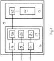
- Fig. 1 shows a schematic block diagram of an apparatus 10 for predicting the state-of-function of a battery.
- the apparatus 10 comprises a sensor unit 12 and an evaluating unit 14.
- the sensor unit 12 is configured to measure a battery voltage, a battery current and a temperature, preferably an engine temperature, battery temperature and/or ambient temperature.
- the sensor unit 12 may comprise a voltage sensor 16, a current sensor 18 and a temperature sensor 20.
- the sensor unit 12 is at least configured for synchronous measurement of battery voltage and current.
- the sensor unit 12 may comprise a synchronous analogue-to-digital converter unit 22.
- the analogue-to-digital converter unit 22 is configured for synchronous analogue-to-digital conversion of battery voltage and battery current measurements by voltage sensor 16 and current sensor 18. Further to this, the analogue-to-digital converter unit 22 may be configured for analogue-to-digital conversion of temperature measurements of temperature sensor 20.
- the analogue-to-digital converter unit 22 may comprise a plurality of analogue-to-digital converters, indicated with numerals 23a, 23b, and 23c. The analogue-to-digital converters 23a, 23b, and 23c may be triggered in common mode in order the analogue-to-digital converter unit 22 to allow a synchronous conversion.
- the evaluating unit 14 may comprise processing unit 24 and data storage 26.
- the processing unit 24 may process data and/or signals from the analogue-to-digital converter 22 and/or data from the storage 26.
- the processing unit 24 may also be configured for triggering the analogue-to-digital converters 23a, 23b, and 23c in common mode.
- the storage 26 particularly comprises software and/or experimental data gathered in the course of product development and/or field data recorded during normal use of the respective product.
- An algorithm particularly a decision tree algorithm or a Naive Bayesian classifier, may be implemented in software stored in the data storage 26.
- the evaluation unit 14 is configured to provide a prediction on a battery state-of-function, in particular a prediction on the crank-ability of an engine starter battery, by conducting at least one comparison operation with experimental data stored in storage 26, preferably data containing positive and/or negative state-of-function events with corresponding parameter values, in particular including internal resistance, temperature and/or state-of-charge values.
- the evaluation unit 14 may also be configured to record determined internal resistance values and/or measured voltages and/or currents for subsequent prediction operations on a battery state-of-function in storage device 26.
- the evaluation unit 14 may furthermore be configured to record a positive and/or negative state-of-function together with corresponding parameter values and/or to conduct self-optimization operations based on said recorded data, preferably for improvement of subsequent prediction operations on a battery state-of-function.
- the self-optimization may concern the data basis stored in the storage 26 and/or the improvement of the algorithm in form of software likewise stored in storage 26.
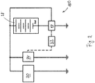
- Fig. 2 shows a schematic block diagram of a vehicle power system 100 with an apparatus 10 as described above.
- the vehicle power system 100 comprises a starter battery 28 for cranking an internal combustion engine, which is not shown here.
- the apparatus 10 may be attached electrically and/or physically to the negative pole of the starter battery 28, which provides energy required to start the respective internal combustion engine by means of engine starter 30.
- the apparatus 10 may be furthermore connected to an alternator control 32, which is configured to control an alternator 34.
- Alternator 34 may be a so called smart alternator, which charges the battery 28 only if needed.
- the apparatus 10 may be connected to an overall power control and/or a vehicle control, not shown here. Accordingly, the apparatus 10 may be configured to obtain further data from an vehicle control and/or engine control unit. For example, locally available information and/or data on the state of the engine may thereby be transmitted to the apparatus 10 by means of a communication network. It is also possible that the apparatus 10, at least partly, forms an overall power control and/or a vehicle control.
- the processing unit 24 and data storage 26 may be part of the respective vehicle control and connected to separately arranged sensors.
- Fig. 3 shows a scatter plot of experimentally gathered data containing parameter values on internal battery resistance, temperature and state-of-function.
- Axis 36 represents the state-of-charge (in %)
- axis 38 the temperature (in degrees Celsius)
- axis 40 the internal resistance (in mOhm).
- every point in the scatter plot of Fig. 3 represents a data set comprising a value for the state-of-charge, a temperature value, and an internal resistance value.
- each point in the scatter plot marks either a positive or a negative state-of-function event, in particular a successful or an unsuccessful crank attempt.
- the plurality of points representing a positive state-of-function event and the plurality of points representing a negative state-of-function event are separated by a three-dimensional curve, not shown in Fig. 3 .
- An according three-dimensional curve may indicate a threshold between a positive and a negative state-of-function, and therefore taken as a basis for the prediction of a state of function.
- An according three-dimensional curve may be expressed by a specific function stored in data storage 26.
- the points representing successful crank attempts are located to the upper left side and marked as a cross, whereas the points representing unsuccessful crank attempts are located to the lower right side and marked as a rhombus. It is conceivable, that the state-of-function is positive at a high temperature, a low internal resistance and a high state-of-charge. On the other hand, the state-of-function is negative at a low temperature, a high internal resistance and a low state-of-charge.
- Fig. 3 The data plotted in Fig. 3 can be gathered experimentally in the course of product development, and preferably also further enhanced during normal product use, thus after product development and entry into market, in particular for reasons of self-optimization.
- Self-optimization operations may, for example, lead to adaptions in the shape of the above mentioned three-dimensional curve between positive and negative state-of-function events, said curve not being shown in Fig. 3 .
- Fig. 4 shows an exemplary decision tree for crank-ability prediction.
- a first threshold for example a threshold of 0.00765 Ohm.
- the decision process proceeds to step 46, in which a negative state-of-function is determined.
- the process proceeds to step 44, in which it is determined whether or not the state-of-charge is below a threshold, for example a threshold of 17.5 %.
- the decision process proceeds to step 50, in which a negative state-of-function is determined.
- step 48 in which it is determined whether or not the temperature, for example an engine temperature, is below a threshold, for example a threshold of -27.5 °C. In case the temperature is above the threshold, the decision process proceeds to step 52, in which a positive state-of-function is determined. Otherwise, the process proceeds to step 54, in which it is determined whether or not the internal resistance is below a second threshold, for example a threshold of 0.0066 Ohm. In case the internal resistance is above the second threshold, the decision process proceeds to step 58, in which a negative state-of-function is determined. If in step 54 the internal resistance is determined to be below the second threshold, the decision process proceeds to step 56, in which a positive state-of-function is determined.
- a threshold for example a threshold of -27.5 °C.
- the decision process proceeds to step 52, in which a positive state-of-function is determined.
- step 54 in which it is determined whether or not the internal resistance is below a second threshold, for example a threshold of 0.0066 Ohm. In case
- Self-optimization may lead to changes in the thresholds and also to the decision tree itself. That is, self-optimization may initiate further decision steps and/or adapted decision orders, whereby the accuracy of prediction may be further improved. Self-optimization may be conducted on the basis of field data gathered during normal operation of the respective product and also further data transmitted to the apparatus from external sources.
- adding an artificial margin to the data sets may provide a more defensive prediction.
- An according effect may be achieved by adding additional data sets for negative state-of-function events with values lower or greater, respectively.
Landscapes
- Physics & Mathematics (AREA)
- General Physics & Mathematics (AREA)
- Secondary Cells (AREA)
Abstract
Description
- The present invention refers to an apparatus and a method for predicting a battery state-of-function, a vehicle power system and vehicle with such an apparatus.
- The term state-of-function (SOF) is used to describe the power capability of a battery, thus the capability to perform a specific function. Predicting the battery state-of-function is increasingly important in various technical fields. For example, modern vehicles are often equipped with energy saving systems, such as an engine start-stop function, which requires a reliable prediction on a battery state-of-function. A start-stop function particularly requires adequate prediction on the capability of a battery to perform a successful crank, hereinafter referred to as "crank-ability". The quality of such prediction has immediate impact on the fuel saving potential of an according function. Apart from this, unsuccessful crank attempts lead to unintended vehicle stops and therefore affect the primary vehicle functions.
- It is known that battery monitoring systems are utilized for state-of-function prediction, said monitoring systems usually providing information about the battery state-of-charge and also the actual quality level of the battery, also known as state-of-health (SOH). However, particularly the measurement or estimation of the battery state-of-health may be complicated or imprecise. That is, end of discharge measurements are barely possible during operation of a vehicle, and estimating models for determining the battery state-of-health, for example based on the number of charging and discharging cycles, may be imprecise. Finally, in many applications the effect of the battery state-of-health on the battery state-of-function may barely be expressed by a specific function, and may therefore not be quantifiable.
- It is therefore an object of the present invention to provide an apparatus and a method for predicting a battery state-of-function, which allows improving the prediction accuracy and/or reducing the complexity of the prediction operation. It is also an object of the present invention to provide a vehicle power system and a motor vehicle equipped with an according apparatus.
- With regard to the apparatus the objective above has been solved by an apparatus according to claim 1 and also by an apparatus according to claim 11. An accordingly equipped vehicle power system is subject to
claim 12, and a motor vehicle is subject of claim 13. With regards the method the above mentioned objective has been solved by the subject matter ofclaims 14 and 15, respectively - According to a first aspect of the present invention, an apparatus for predicting a battery state-of-function comprises a sensor unit configured for synchronously measuring a battery voltage and a battery current, and an evaluation unit for evaluating quantities measured by the sensor unit. The evaluation unit is configured to determine at least the internal resistance of a battery based on a synchronous measurement of a battery voltage and a battery current by the sensor unit during at least one previous high current dynamic discharging event.
- In the present context, high current discharge is considered as a discharge current which amounts to at least 20%, preferably more than 25%, more than 30%, more than 40%, or more than 50% of a specified maximum discharge current of the respective battery. The specified maximum discharge current of the respective battery may, for example, be a cold cranking amps (CCA) value, a maximum 30-sec discharge pulse current - defined as a maximum current at which the battery can be discharged for pulses of up to 30 seconds - or a maximum continuous discharge current - defined as the maximum current at which the battery can be discharged continuously.
- In case of a starter battery for a passenger car, a high current discharge current may for example amount to at least 100 A, preferably more than 150 A, more than 200 A, or more than 250 A. As an example, a high current discharge in case of a starter battery of a passenger car may amount to about 300 A. In case of a starter battery for a truck, a high current discharge current may for example amount to at least 200 A, preferably more than 300 A, more than 400 A, or more than 500 A. As an example, a high current discharge in case of a starter battery of a truck may amount to about 600 A.
- Furthermore, dynamic discharging is to be understood as a discharge with variations in the discharging current during the time of the discharging event.
- By synchronously measuring a battery voltage and a battery current during a high current dynamic discharging event, the internal resistance during said high current dynamic discharging event may be precisely measured. The synchronous measurement particularly allows avoiding falsifications due to phase displacements. Accordingly, synchronous measurement in the sense of the present teaching may comprise simultaneous detection on the one hand and synchronous processing of the detected quantities on the other hand. Determining the internal resistance on the basis of a synchronous measurement during a previous high current dynamic discharging event allows a conclusion on the internal resistance to be expected during a subsequent high current dynamic discharging event, in particular in case of providing a specific function. In other words, a precise measurement of the internal resistance during a high current dynamic discharging event by synchronous measurement of voltage and current allows, with high precision, to estimate the internal resistance to be expected during a subsequent high current dynamic discharging event, which is comparable to the previous one. Thus, the resistance behaviour of the battery during an upcoming high current discharging event, particularly while providing a specific functionality, may be suitably predicted, which in turn allows an improved and/or simplified prediction on the battery state-of-fu nction.
- According to a preferred embodiment of the present invention, the evaluation unit is configured to determine at least the internal resistance of a starter battery based on a synchronous measurement of the battery voltage and the battery current by the sensor unit during at least one previous crank-operation of an internal combustion engine. Thereby, the crank-ability of an engine starter battery may be suitably predicted.
- According to a further preferred embodiment, the evaluation unit is configured to determine the internal resistance based on a plurality of synchronous measurements of battery voltage and battery current by the sensor unit during a plurality of previous high current dynamic discharging events, preferably a plurality of previous crank-operations of an internal combustion engine. Thereby, the accuracy of prediction may be improved and also the progression of the internal resistance value throughout the battery lifecycle may be recorded.
- Preferably, the sensor unit comprises a voltage sensor and/or a current sensor and/or an analogue-to-digital converter unit, in particular for simultaneous sampling. The analogue-to-digital converter unit may particularly be configured for simultaneous analogue-to-digital conversion of battery voltage and battery current measurements. Thus, by providing an according analogue-to-digital converter unit, the simultaneous measurement of voltage and current may be conducted with high precision, particularly without the risk of adverse effects caused by phase shifting. The analogue-to-digital converter unit may preferably comprise a plurality of analogue-to-digital converters. In this case each analogue-to-digital converter may be configured to convert one sensor signal. The different analogue-to-digital converters may be triggered in common mode, in order to allow a synchronous measurement.
- According to a further embodiment, the sensor unit is configured to measure a temperature and/or comprises a temperature sensor, preferably for measuring an engine temperature, battery temperature and/or ambient temperature. The possibility of measuring a temperature allows a more precise prediction on the battery state-of-function, as the latter may be affected by temperature.
- Furthermore, the sensor unit and/or the evaluating unit may be configured to obtain external sensor data, particularly from an external temperature sensor. Such an external temperature sensor may, for example, be a temperature sensor configured for measuring an engine temperature. The sensor unit and/or the evaluating unit may be configured to obtain external sensor data via a communication network, such as a data bus. This allows also external sensor data, particularly temperature data, to be used for prediction operations.
- The engine temperature allows a conclusion on the required force for cranking the engine, and therefore the required energy from the battery. The battery temperature may provide information on thermodynamic effects, which concern the ability of the battery to deliver energy. For example, the internal resistance of a battery may be affected by temperature. The battery temperature may also allow conclusions on the engine temperature. That is, a high battery temperature may for example be an indicator for a high engine temperature, and vice versa. Finally, the ambient temperature allows a conclusion on the temperature of the engine and/or battery at the time of an initial crank-operation of an internal combustion engine.
- According to a further preferred embodiment, the sensor unit is configured to measure a battery equilibrium voltage and/or configured for coulomb counting. In this case, the evaluation unit may be configured to determine a battery state-of-charge particularly on the basis of measurement of a battery equilibrium voltage and/or coulomb counting. This allows a reliable assessment of the battery state-of-charge. Here, state-of-charge is to be understood as the ratio of the stored energy (charge) to the actual capacity of the battery.
- Furthermore, the evaluation unit may be configured to provide a prediction on a battery state-of-function, in particular a prediction on the crank-ability of an engine starter battery, on the basis of a plurality of parameters, preferably a determined internal resistance, a measured temperature and/or a determined state-of-charge. As mentioned above, the measured temperature may be engine temperature, battery temperature and/or ambient temperature. By using a determined internal resistance as a basis for a state-of-function prediction, the explicit determination of a rather complicated or imprecise state-of-health value may be omitted. Instead, the internal resistance determined at a high current dynamic discharging event is a sufficient indicator for the state-of-health, which together with further parameters, such as temperature and state-of-charge is suitable for a state-of-function prediction.
- According to a further embodiment, the evaluation unit may be configured to provide a prediction on a battery state-of-function, in particular a prediction on the crank-ability of an engine starter battery, on the basis of a limited number of parameters, preferably comprising a determined internal resistance, a measured temperature and a determined state-of-charge, only.
- The limitation to a comparably small set of parameters allows a lean data structure and therewith also a simplified algorithm for state-of-function prediction. Also the enhancement of the prediction function, for example by gathering field data, may be simplified with a lean data structure. Even though the size of non-volatile memory available may be limited, relevant data may be stored and continuously expanded.
- At the same time, the values for internal resistance, temperature and state-of-charge may form a satisfactory set of parameters, particularly with barely any redundant information for a state-of-function prediction. Temperature represents possible thermodynamic effects on the battery ability to deliver energy. SOC represents the impact of the percentage of energy stored in relation to battery actual capacity. And internal resistance represents effects of the attrition and gradual degradation of battery during usage over the lifetime. These factors have been found to be satisfactory for determining the state-of-function of a battery. Referring to correlating or strongly dependent parameters is undesired since redundant parameters normally do not carry additional information while keeping the costs of storing and/or gathering data unnecessarily high.
- More preferably, the evaluation unit may be configured to provide a prediction on a battery state-of-function on the basis of a previously determined internal resistance, a temperature currently measured and/or a state-of-charge currently measured and/or estimated. Thus, the evaluation unit may take a previously measured internal resistance together with currently measured temperature values and currently estimated and/or measured values for the state-of-charge as a basis for prediction operations.
- According to yet a further embodiment, the evaluation unit may be configured to provide a prediction on a battery state-of-function, in particular a prediction on the crank-ability of an engine starter battery, on the basis of a decision tree algorithm. Decision tree algorithms may have a simple structure and provide a robust functionality. The required hardware can therefore also have a simple and cost-effective design. The decision tree algorithm may be implemented in specific software, wherein said software may be stored in a suitable data storage of the evaluation unit.
- According to a yet a further embodiment, the evaluation unit may be configured to provide a prediction on a battery state-of-function, in particular a prediction on the crank-ability of an engine starter battery, by conducting at least one comparison operation with stored experimental data. The experimental data may be gathered in the course of product development, and possibly enhanced during field operation. Preferably the experimental data contains data on internal battery resistance, temperature and/or state-of-charge. More preferably, the experimental data contains data containing positive and/or negative state-of-functions with corresponding parameter values, in particular including internal resistance, temperature and/or state-of-charge values. That is, the experimental data may contain data on successful and/or unsuccessful crank events, and the corresponding values on internal resistance, temperature and/or state-of-charge. Each positive and/or negative event may be associated with a set of parameter values, such that the experimental data may provide a multi-dimensional state-of-function map.
- In a further preferred embodiment, the evaluation unit is configured to record determined internal resistance values and/or measured voltages and/or currents for subsequent prediction operations on a battery state-of-function. In order to provide a suitable recording capability, the evaluation unit may comprise a storage device. The storage device may accordingly be configured to store internal resistance values and/or measured voltages and/or currents for subsequent prediction operations on a battery state-of-fu nction.
- The evaluation unit may be configured to determine and/or record the internal battery resistance periodically. Furthermore the senor unit may be configured for continuous measurement and/or recording of the current and/or voltage and/or temperature. A solid data basis for subsequent prediction operations may thereby be provided.
- In a further preferred embodiment, the evaluation unit may be configured to record a positive and/or negative state-of-function together with corresponding parameter values, preferably comprising a determined internal resistance, measured temperature and/or a determined state-of-charge. The data basis may thereby be suitably enhanced. More preferably, the evaluation unit may be configured to conduct self-optimization operations based on said recorded data, preferably for improvement of subsequent prediction operations on a battery state-of-function. The self-optimization operations may, for example, increase the number of data sets for increased accuracy and/or the adaptation of the decision tree algorithm. Any recorded data may be stored in a storage device. Thus, the storage device may be configured to store recorded data containing a positive and/or negative state-of-function together with corresponding parameter values.
- An apparatus for predicting a battery state-of-function according to a second aspect of the present invention comprises a evaluating unit configured to predict a battery state-of-function only on the basis of a determined internal battery resistance, a measured temperature and a determined state-of-charge. The apparatus may be configured to predict the crank-ability of an engine starter battery. By predicting the battery state-of-function only on this limited set of parameters a lean data structure and also a simplified algorithm for state-of-function prediction. Also the enhancement of the prediction function, for example on the basis of gathered field data, may be simplified with a lean data structure.
- The further features mentioned above may likewise be applied to the apparatus according to the second aspect of the present invention.
- The present invention furthermore refers to a vehicle power system, in particular for a motor vehicle, comprising at least one battery, preferably a starter battery for an internal combustion engine, and an apparatus described above.
- The present invention also refers to a motor vehicle, in particular a passenger car or truck, comprising an apparatus and a vehicle power system described above.
- According to a third aspect of the present invention, a method for predicting a battery state-of-function, in particular the crank-ability of an engine starter battery, comprises the steps of synchronously measuring a battery voltage and a battery current during at least one high current dynamic discharging event, and determining at least the internal resistance of a battery based on the previous synchronous measurement of the battery voltage and the battery current.
- As mentioned above, by synchronously measuring a battery voltage and a battery current during a high current dynamic discharging event, the internal resistance during said high current dynamic discharging event may be precisely measured. Determining the internal resistance on the basis of a synchronous measurement during a previous high current dynamic discharging event allows a conclusion on the internal resistance to be expected during a subsequent high current dynamic discharging event, in particular in case of providing a specific function. The resistance behaviour of the battery during an upcoming discharging event may thus be suitably predicted, which in turn allows an improved and/or simplified prediction on the battery state-of-function.
- According to a fourth aspect of the present invention, a method for predicting a battery state-of-function, in particular the crank-ability of an engine starter battery, comprises the steps of determining an internal battery resistance, determining a battery state-of-charge, measuring a temperature, preferably an engine temperature, battery temperature and/or ambient temperature, and providing a battery state-of-function prediction only on the basis of the determined internal battery resistance, determined battery state-of-charge and measured temperature.
- By providing a battery state-of-function prediction only on this limited set of parameters a lean data structure and also a simplified algorithm for state-of-function prediction. Also the enhancement of the prediction function, for example on the basis of gathered field data, may be simplified with a lean data structure.
- The features and advantages of the various embodiments of the present invention will, in the following, be described with reference to the figures.
- Fig. 1
- shows a schematic block diagram of an apparatus for predicting the state-of-function of a battery;
- Fig. 2
- shows a schematic block diagram of a vehicle power system with an apparatus of
Figure 1 ; - Fig. 3
- shows a scatter plot of experimentally gathered data with parameter values on internal battery resistance, temperature and state-of-function.
- Fig. 4
- shows an exemplary decision tree for crank-ability prediction.
-
Fig. 1 shows a schematic block diagram of anapparatus 10 for predicting the state-of-function of a battery. Theapparatus 10 comprises asensor unit 12 and an evaluatingunit 14. Thesensor unit 12 is configured to measure a battery voltage, a battery current and a temperature, preferably an engine temperature, battery temperature and/or ambient temperature. For conducting the respective measuring operations, thesensor unit 12 may comprise avoltage sensor 16, acurrent sensor 18 and atemperature sensor 20. - The
sensor unit 12 is at least configured for synchronous measurement of battery voltage and current. For conducting synchronous measurement of battery voltage and current, thesensor unit 12 may comprise a synchronous analogue-to-digital converter unit 22. Thus, the analogue-to-digital converter unit 22 is configured for synchronous analogue-to-digital conversion of battery voltage and battery current measurements byvoltage sensor 16 andcurrent sensor 18. Further to this, the analogue-to-digital converter unit 22 may be configured for analogue-to-digital conversion of temperature measurements oftemperature sensor 20. For conducting synchronous analogue-to-digital conversions, the analogue-to-digital converter unit 22 may comprise a plurality of analogue-to-digital converters, indicated withnumerals digital converters digital converter unit 22 to allow a synchronous conversion. - The evaluating
unit 14 may comprise processingunit 24 anddata storage 26. Theprocessing unit 24 may process data and/or signals from the analogue-to-digital converter 22 and/or data from thestorage 26. Theprocessing unit 24 may also be configured for triggering the analogue-to-digital converters storage 26 particularly comprises software and/or experimental data gathered in the course of product development and/or field data recorded during normal use of the respective product. An algorithm, particularly a decision tree algorithm or a Naive Bayesian classifier, may be implemented in software stored in thedata storage 26. - The
evaluation unit 14 is configured to provide a prediction on a battery state-of-function, in particular a prediction on the crank-ability of an engine starter battery, by conducting at least one comparison operation with experimental data stored instorage 26, preferably data containing positive and/or negative state-of-function events with corresponding parameter values, in particular including internal resistance, temperature and/or state-of-charge values. Theevaluation unit 14 may also be configured to record determined internal resistance values and/or measured voltages and/or currents for subsequent prediction operations on a battery state-of-function instorage device 26. - The
evaluation unit 14 may furthermore be configured to record a positive and/or negative state-of-function together with corresponding parameter values and/or to conduct self-optimization operations based on said recorded data, preferably for improvement of subsequent prediction operations on a battery state-of-function. The self-optimization may concern the data basis stored in thestorage 26 and/or the improvement of the algorithm in form of software likewise stored instorage 26. -
Fig. 2 shows a schematic block diagram of avehicle power system 100 with anapparatus 10 as described above. Thevehicle power system 100 comprises astarter battery 28 for cranking an internal combustion engine, which is not shown here. Theapparatus 10 may be attached electrically and/or physically to the negative pole of thestarter battery 28, which provides energy required to start the respective internal combustion engine by means ofengine starter 30. - The
apparatus 10 may be furthermore connected to analternator control 32, which is configured to control analternator 34.Alternator 34 may be a so called smart alternator, which charges thebattery 28 only if needed. Theapparatus 10 may be connected to an overall power control and/or a vehicle control, not shown here. Accordingly, theapparatus 10 may be configured to obtain further data from an vehicle control and/or engine control unit. For example, locally available information and/or data on the state of the engine may thereby be transmitted to theapparatus 10 by means of a communication network. It is also possible that theapparatus 10, at least partly, forms an overall power control and/or a vehicle control. For example, theprocessing unit 24 anddata storage 26 may be part of the respective vehicle control and connected to separately arranged sensors. -
Fig. 3 shows a scatter plot of experimentally gathered data containing parameter values on internal battery resistance, temperature and state-of-function.Axis 36 represents the state-of-charge (in %),axis 38 the temperature (in degrees Celsius), andaxis 40 the internal resistance (in mOhm). Thus, every point in the scatter plot ofFig. 3 represents a data set comprising a value for the state-of-charge, a temperature value, and an internal resistance value. Furthermore, each point in the scatter plot marks either a positive or a negative state-of-function event, in particular a successful or an unsuccessful crank attempt. The plurality of points representing a positive state-of-function event and the plurality of points representing a negative state-of-function event are separated by a three-dimensional curve, not shown inFig. 3 . An according three-dimensional curve may indicate a threshold between a positive and a negative state-of-function, and therefore taken as a basis for the prediction of a state of function. An according three-dimensional curve may be expressed by a specific function stored indata storage 26. - In the scatter plot of
Fig. 3 , the points representing successful crank attempts are located to the upper left side and marked as a cross, whereas the points representing unsuccessful crank attempts are located to the lower right side and marked as a rhombus. It is conceivable, that the state-of-function is positive at a high temperature, a low internal resistance and a high state-of-charge. On the other hand, the state-of-function is negative at a low temperature, a high internal resistance and a low state-of-charge. - The data plotted in
Fig. 3 can be gathered experimentally in the course of product development, and preferably also further enhanced during normal product use, thus after product development and entry into market, in particular for reasons of self-optimization. Self-optimization operations may, for example, lead to adaptions in the shape of the above mentioned three-dimensional curve between positive and negative state-of-function events, said curve not being shown inFig. 3 . -
Fig. 4 shows an exemplary decision tree for crank-ability prediction. In afirst step 42 it is determined whether or not the internal resistance is below a first threshold, for example a threshold of 0.00765 Ohm. In case the internal resistance is above the first threshold, the decision process proceeds to step 46, in which a negative state-of-function is determined. Otherwise, the process proceeds to step 44, in which it is determined whether or not the state-of-charge is below a threshold, for example a threshold of 17.5 %. In case the state-of-charge is below the threshold, the decision process proceeds to step 50, in which a negative state-of-function is determined. Otherwise, the process proceeds to step 48, in which it is determined whether or not the temperature, for example an engine temperature, is below a threshold, for example a threshold of -27.5 °C. In case the temperature is above the threshold, the decision process proceeds to step 52, in which a positive state-of-function is determined. Otherwise, the process proceeds to step 54, in which it is determined whether or not the internal resistance is below a second threshold, for example a threshold of 0.0066 Ohm. In case the internal resistance is above the second threshold, the decision process proceeds to step 58, in which a negative state-of-function is determined. If instep 54 the internal resistance is determined to be below the second threshold, the decision process proceeds to step 56, in which a positive state-of-function is determined. - Single or combined features above concerning the decision tree of
Fig. 4 may be combined with further features in the claims, the description and the other figures. - The thresholds mentioned above are exemplary only. Self-optimization may lead to changes in the thresholds and also to the decision tree itself. That is, self-optimization may initiate further decision steps and/or adapted decision orders, whereby the accuracy of prediction may be further improved. Self-optimization may be conducted on the basis of field data gathered during normal operation of the respective product and also further data transmitted to the apparatus from external sources.
- If generating a false positive prediction is considered more damaging than the false-negative prediction, adding an artificial margin to the data sets may provide a more defensive prediction. An according effect may be achieved by adding additional data sets for negative state-of-function events with values lower or greater, respectively.
- As regards the data basis stored in the
data storage 26 and shown in the plot ofFig. 3 , it may be important to have a suitable representation of negative state-of-function data sets, thus unsuccessful events. The proposed ratio between positive and negative state-of-function data sets, thus successful and unsuccessful events, may be approximately 4:1. However, since negative state-of-function events, such as unsuccessful crank attempts, may not be very frequent in a lifetime of a product, such as a vehicle, it may be possible to utilize experienced negative state-of-function events to expand future data sets. According field data gathered during normal operation may be continuously and/or periodically transmitted for further improving future data bases. Said field data may also be collected at an end-of-life point of the respective product. -
- 10
- apparatus for predicting a battery state-of-function
- 12
- sensor unit
- 14
- evaluating unit
- 16
- voltage sensor
- 18
- current sensor
- 20
- temperature sensor
- 22
- analogue-to-digital converter unit
- 23a-23c
- analogue-to-digital converter
- 24
- processing unit
- 26
- data storage
- 28
- starter battery
- 30
- starter
- 32
- alternator control
- 34
- alternator
- 36
- SOC axis
- 38
- temperature axis
- 40
- internal resistance axis
- 42-58
- steps in decision process
- 100
- vehicle power system
Claims (15)
- Apparatus (10) for predicting a battery state-of-function, in particular the crank-ability of an engine starter battery (28), comprising a sensor unit (12) configured for synchronously measuring a battery voltage and a battery current, and an evaluation unit (14) for evaluating quantities measured by the sensor unit (12), wherein the evaluation unit (14) is configured to determine at least the internal resistance of a battery (28) based on a synchronous measurement of a battery voltage and a battery current by the sensor unit (12) during at least one previous high current dynamic discharging event.
- Apparatus (10) according to claim 1, wherein the sensor unit comprises a voltage sensor (16) and/or a current sensor (18) and/or an analogue-to-digital converter unit (22), in particular for simultaneous sampling, preferably for simultaneous analogue-to-digital conversion of battery voltage and battery current measurements, more preferably comprising a plurality of analogue-to-digital converters (23a-23c).
- Apparatus (10) according to claim 1 or 2, wherein the sensor unit (12) is configured to measure a temperature and/or comprises a temperature sensor (20), preferably for measuring an engine temperature, battery temperature and/or ambient temperature.
- Apparatus (10) according to any one of the preceding claims, wherein the sensor unit (12) is configured to measure a battery equilibrium voltage and/or configured for coulomb counting and/or wherein the evaluation unit is configured to determine a battery state-of-charge, in particular on the basis of measurement of a battery equilibrium voltage and/or coulomb counting.
- Apparatus (10) according to any one of the preceding claims, wherein the evaluation unit (14) is configured to provide a prediction on a battery state-of-function, in particular a prediction on the crank-ability of an engine starter battery (28), on the basis of a plurality of parameters, preferably a determined internal resistance, a measured temperature and/or a determined state-of-charge.
- Apparatus (10) according to any one of the preceding claims, wherein the evaluation unit (14) is configured to provide a prediction on a battery state-of-function, in particular a prediction on the crank-ability of an engine starter battery (28), on the basis of a limited number of parameters, preferably comprising a determined internal resistance, a measured temperature and a determined state-of-charge, only.
- Apparatus (10) according to any one of the preceding claims, wherein the evaluation unit (14) is configured to provide a prediction on a battery state-of-function, in particular a prediction on the crank-ability of an engine starter battery (28), on the basis of a decision tree algorithm.
- Apparatus (10) according to any one of the preceding claims, wherein the evaluation unit (14) is configured to provide a prediction on a battery state-of-function, in particular a prediction on the crank-ability of an engine starter battery (28), by conducting at least one comparison operation with stored experimental data, preferably with experimental data concerning internal battery resistance, temperature and/or state-of-charge, more preferably data containing positive and/or negative state-of-functions with corresponding parameter values, in particular including internal resistance, temperature and/or state-of-charge values.
- Apparatus (10) according to any one of the preceding claims, wherein the evaluation unit (14) is configured to record determined internal resistance values and/or measured voltages and/or currents for subsequent prediction operations on a battery state-of-function, preferably in a storage device (26) of the evaluation unit (14).
- Apparatus (10) according to any one of the preceding claims, wherein the evaluation unit (14) is configured to record a positive and/or negative state-of-function together with corresponding parameter values, preferably comprising a determined internal resistance, measured temperature and/or a determined state-of-charge, and/or to conduct self-optimization operations based on said recorded data, preferably for improvement of subsequent prediction operations on a battery state-of-function.
- Apparatus (10) for predicting a battery state-of-function, in particular the crank-ability of an engine starter battery (28), comprising an evaluating unit (14) configured to predict a battery state-of-function only on the basis of a determined internal battery resistance, a measured temperature and a determined state-of-charge.
- Vehicle power system (100), in particular for a motor vehicle, comprising at least one battery (28), preferably a starter battery for an internal combustion engine, and an apparatus (10) according to one of the preceding claims.
- Motor vehicle, in particular passenger car or truck, comprising an apparatus (10) according to any one of claims 1 to 11 and/or a vehicle power system (100) according to claim 12.
- Method for predicting a battery state-of-function, in particular the crank-ability of an engine starter battery (28), comprising the steps of:- Synchronously measuring a battery voltage and a battery current during at least one high current dynamic discharging event, and- determining at least the internal resistance of a battery based on the previous synchronous measurement of the battery voltage and the battery current.
- Method for predicting a battery state-of-function, in particular the crank-ability of an engine starter battery (28), comprising the steps of:- Determining an internal battery resistance,- determining a battery state-of-charge,- measuring a temperature, preferably an engine temperature, battery temperature and/or ambient temperature, and- providing a battery state-of-function prediction only on the basis of the determined internal battery resistance, determined battery state-of-charge and measured temperature.
Priority Applications (1)
| Application Number | Priority Date | Filing Date | Title |
|---|---|---|---|
| EP17196103.0A EP3470859B1 (en) | 2017-10-12 | 2017-10-12 | Apparatus and method for predicting a battery state-of-function |
Applications Claiming Priority (1)
| Application Number | Priority Date | Filing Date | Title |
|---|---|---|---|
| EP17196103.0A EP3470859B1 (en) | 2017-10-12 | 2017-10-12 | Apparatus and method for predicting a battery state-of-function |
Publications (2)
| Publication Number | Publication Date |
|---|---|
| EP3470859A1 true EP3470859A1 (en) | 2019-04-17 |
| EP3470859B1 EP3470859B1 (en) | 2024-07-17 |
Family
ID=60083189
Family Applications (1)
| Application Number | Title | Priority Date | Filing Date |
|---|---|---|---|
| EP17196103.0A Active EP3470859B1 (en) | 2017-10-12 | 2017-10-12 | Apparatus and method for predicting a battery state-of-function |
Country Status (1)
| Country | Link |
|---|---|
| EP (1) | EP3470859B1 (en) |
Cited By (4)
| Publication number | Priority date | Publication date | Assignee | Title |
|---|---|---|---|---|
| CN113466730A (en) * | 2021-06-30 | 2021-10-01 | 郑州易能科技有限公司 | Storage battery internal resistance flash measurement device and method |
| CN114675098A (en) * | 2021-04-21 | 2022-06-28 | 北京新能源汽车股份有限公司 | A method and device for determining a charging fault |
| CN115079011A (en) * | 2022-07-19 | 2022-09-20 | 上海洛轲智能科技有限公司 | Vehicle SOF estimation method and device and vehicle |
| RU2782959C1 (en) * | 2021-06-23 | 2022-11-08 | федеральное государственное бюджетное образовательное учреждение высшего образования «Оренбургский государственный университет» | Method for assessment of technical condition of starter accumulator batteries |
Citations (5)
| Publication number | Priority date | Publication date | Assignee | Title |
|---|---|---|---|---|
| WO2011083062A1 (en) * | 2010-01-05 | 2011-07-14 | Robert Bosch Gmbh | Method for detecting the ability to start |
| FR2975190A1 (en) * | 2011-05-13 | 2012-11-16 | Valeo Equip Electr Moteur | METHOD FOR ESTIMATING THE OPERATING STATE OF A BATTERY FOR AN AUTOMATIC STOP / RELEASE SYSTEM OF THE THERMAL MOTOR OF A VEHICLE, SENSOR AND BATTERY MANAGEMENT SYSTEM ADAPTED |
| FR2975188A1 (en) * | 2011-05-13 | 2012-11-16 | Valeo Equip Electr Moteur | METHOD FOR ESTIMATING THE HEALTH CONDITION OF A BATTERY AND ADAPTED BATTERY MANAGEMENT SYSTEM |
| EP2940273A1 (en) * | 2012-12-27 | 2015-11-04 | Toyota Jidosha Kabushiki Kaisha | Vehicle, control device, and control method |
| US20160091573A1 (en) * | 2014-09-30 | 2016-03-31 | Gs Yuasa International Ltd. | Battery deterioration determination device, battery deterioration determination method, and vehicle |
-
2017
- 2017-10-12 EP EP17196103.0A patent/EP3470859B1/en active Active
Patent Citations (5)
| Publication number | Priority date | Publication date | Assignee | Title |
|---|---|---|---|---|
| WO2011083062A1 (en) * | 2010-01-05 | 2011-07-14 | Robert Bosch Gmbh | Method for detecting the ability to start |
| FR2975190A1 (en) * | 2011-05-13 | 2012-11-16 | Valeo Equip Electr Moteur | METHOD FOR ESTIMATING THE OPERATING STATE OF A BATTERY FOR AN AUTOMATIC STOP / RELEASE SYSTEM OF THE THERMAL MOTOR OF A VEHICLE, SENSOR AND BATTERY MANAGEMENT SYSTEM ADAPTED |
| FR2975188A1 (en) * | 2011-05-13 | 2012-11-16 | Valeo Equip Electr Moteur | METHOD FOR ESTIMATING THE HEALTH CONDITION OF A BATTERY AND ADAPTED BATTERY MANAGEMENT SYSTEM |
| EP2940273A1 (en) * | 2012-12-27 | 2015-11-04 | Toyota Jidosha Kabushiki Kaisha | Vehicle, control device, and control method |
| US20160091573A1 (en) * | 2014-09-30 | 2016-03-31 | Gs Yuasa International Ltd. | Battery deterioration determination device, battery deterioration determination method, and vehicle |
Cited By (5)
| Publication number | Priority date | Publication date | Assignee | Title |
|---|---|---|---|---|
| CN114675098A (en) * | 2021-04-21 | 2022-06-28 | 北京新能源汽车股份有限公司 | A method and device for determining a charging fault |
| RU2782959C1 (en) * | 2021-06-23 | 2022-11-08 | федеральное государственное бюджетное образовательное учреждение высшего образования «Оренбургский государственный университет» | Method for assessment of technical condition of starter accumulator batteries |
| CN113466730A (en) * | 2021-06-30 | 2021-10-01 | 郑州易能科技有限公司 | Storage battery internal resistance flash measurement device and method |
| RU2795423C2 (en) * | 2021-10-04 | 2023-05-03 | Общество с ограниченной ответственностью "ФОРВАРД РИСЕРЧ ЭНД ДЕВЕЛОПМЕНТ" (ООО "ФОРВАРД РИСЕРЧ ЭНД ДЕВЕЛОПМЕНТ") | Built-in device for remote battery control |
| CN115079011A (en) * | 2022-07-19 | 2022-09-20 | 上海洛轲智能科技有限公司 | Vehicle SOF estimation method and device and vehicle |
Also Published As
| Publication number | Publication date |
|---|---|
| EP3470859B1 (en) | 2024-07-17 |
Similar Documents
| Publication | Publication Date | Title |
|---|---|---|
| US11774503B2 (en) | Battery life learning device, battery life prediction device, method and non-transitory computer readable medium | |
| EP3588115B1 (en) | Apparatus and method for estimating a state of charge of a battery | |
| JP6479650B2 (en) | Secondary battery state detection device and secondary battery state detection method | |
| US7154247B2 (en) | Secondary battery state-of-charge estimating apparatus and method using polarization voltages, and recording medium usable thereby | |
| US20170115355A1 (en) | Maximum capacity estimator for battery state of health and state of charge determinations | |
| EP3410137B1 (en) | Cell state estimation device, cell control device, cell system, and cell state estimation method | |
| JP4274382B2 (en) | Calculation method of internal resistance of secondary battery for vehicle | |
| KR102944037B1 (en) | Method for Estimating Internal Resistance of a Secondary Battery and Secondary Battery Anomaly Detection System | |
| US20140218040A1 (en) | Method for estimating the state of charge of a battery, and battery management system using the method | |
| WO2017143830A1 (en) | Method and device for detecting state of health of battery, and battery management system | |
| JPWO2016129248A1 (en) | Secondary battery charge state estimation device and charge state estimation method | |
| KR20160000317A (en) | Method and device to learn and estimate battery state information | |
| EP2720055A2 (en) | Device and method for estimating chargeable/dischargeable power of electric storage device | |
| US20130204561A1 (en) | Device And Method For Determining A Range Of A Battery Characteristic Curve | |
| EP3470859B1 (en) | Apparatus and method for predicting a battery state-of-function | |
| KR20150121526A (en) | Method and device to estimate battery lifetime during driving of electrical vehicle | |
| EP3371613B1 (en) | A system and a method for determining state-of-charge of a battery | |
| CN109839597A (en) | Determine method, battery apparatus and the motor vehicle of the current state of charge of battery | |
| US20150056478A1 (en) | Lithium-ion secondary battery system, inspection method for lithium-ion secondary battery, and control method for lithium-ion secondary battery | |
| WO2025246126A1 (en) | Battery state-of-energy health assessment method and apparatus, and electronic device and readable storage medium | |
| JP2012189373A (en) | Secondary battery condition detection device and secondary battery condition detection method | |
| CN111316115A (en) | Method for detecting self-discharge defects in battery cells | |
| CN118818359B (en) | Battery health state acquisition method and device | |
| CN107064818B (en) | Battery pack SOH evaluation method and system | |
| CN114002605B (en) | Battery health state estimation method and system |
Legal Events
| Date | Code | Title | Description |
|---|---|---|---|
| PUAI | Public reference made under article 153(3) epc to a published international application that has entered the european phase |
Free format text: ORIGINAL CODE: 0009012 |
|
| STAA | Information on the status of an ep patent application or granted ep patent |
Free format text: STATUS: THE APPLICATION HAS BEEN PUBLISHED |
|
| AK | Designated contracting states |
Kind code of ref document: A1 Designated state(s): AL AT BE BG CH CY CZ DE DK EE ES FI FR GB GR HR HU IE IS IT LI LT LU LV MC MK MT NL NO PL PT RO RS SE SI SK SM TR |
|
| AX | Request for extension of the european patent |
Extension state: BA ME |
|
| STAA | Information on the status of an ep patent application or granted ep patent |
Free format text: STATUS: REQUEST FOR EXAMINATION WAS MADE |
|
| 17P | Request for examination filed |
Effective date: 20191008 |
|
| RBV | Designated contracting states (corrected) |
Designated state(s): AL AT BE BG CH CY CZ DE DK EE ES FI FR GB GR HR HU IE IS IT LI LT LU LV MC MK MT NL NO PL PT RO RS SE SI SK SM TR |
|
| STAA | Information on the status of an ep patent application or granted ep patent |
Free format text: STATUS: EXAMINATION IS IN PROGRESS |
|
| 17Q | First examination report despatched |
Effective date: 20220805 |
|
| RAP3 | Party data changed (applicant data changed or rights of an application transferred) |
Owner name: APTIV TECHNOLOGIES LIMITED |
|
| GRAP | Despatch of communication of intention to grant a patent |
Free format text: ORIGINAL CODE: EPIDOSNIGR1 |
|
| STAA | Information on the status of an ep patent application or granted ep patent |
Free format text: STATUS: GRANT OF PATENT IS INTENDED |
|
| RIC1 | Information provided on ipc code assigned before grant |
Ipc: G01R 31/389 20190101ALN20240304BHEP Ipc: G01R 31/367 20190101ALN20240304BHEP Ipc: G01R 31/36 20190101AFI20240304BHEP |
|
| INTG | Intention to grant announced |
Effective date: 20240320 |
|
| RAP1 | Party data changed (applicant data changed or rights of an application transferred) |
Owner name: APTIV TECHNOLOGIES AG |
|
| GRAS | Grant fee paid |
Free format text: ORIGINAL CODE: EPIDOSNIGR3 |
|
| GRAA | (expected) grant |
Free format text: ORIGINAL CODE: 0009210 |
|
| STAA | Information on the status of an ep patent application or granted ep patent |
Free format text: STATUS: THE PATENT HAS BEEN GRANTED |
|
| P01 | Opt-out of the competence of the unified patent court (upc) registered |
Effective date: 20240528 |
|
| AK | Designated contracting states |
Kind code of ref document: B1 Designated state(s): AL AT BE BG CH CY CZ DE DK EE ES FI FR GB GR HR HU IE IS IT LI LT LU LV MC MK MT NL NO PL PT RO RS SE SI SK SM TR |
|
| REG | Reference to a national code |
Ref country code: GB Ref legal event code: FG4D |
|
| REG | Reference to a national code |
Ref country code: CH Ref legal event code: EP |
|
| REG | Reference to a national code |
Ref country code: DE Ref legal event code: R096 Ref document number: 602017083327 Country of ref document: DE |
|
| REG | Reference to a national code |
Ref country code: IE Ref legal event code: FG4D |
|
| RAP4 | Party data changed (patent owner data changed or rights of a patent transferred) |
Owner name: APTIV TECHNOLOGIES AG |
|
| REG | Reference to a national code |
Ref country code: LT Ref legal event code: MG9D |
|
| REG | Reference to a national code |
Ref country code: NL Ref legal event code: MP Effective date: 20240717 |
|
| PG25 | Lapsed in a contracting state [announced via postgrant information from national office to epo] |
Ref country code: PT Free format text: LAPSE BECAUSE OF FAILURE TO SUBMIT A TRANSLATION OF THE DESCRIPTION OR TO PAY THE FEE WITHIN THE PRESCRIBED TIME-LIMIT Effective date: 20241118 |
|
| REG | Reference to a national code |
Ref country code: AT Ref legal event code: MK05 Ref document number: 1704628 Country of ref document: AT Kind code of ref document: T Effective date: 20240717 |
|
| PG25 | Lapsed in a contracting state [announced via postgrant information from national office to epo] |
Ref country code: NL Free format text: LAPSE BECAUSE OF FAILURE TO SUBMIT A TRANSLATION OF THE DESCRIPTION OR TO PAY THE FEE WITHIN THE PRESCRIBED TIME-LIMIT Effective date: 20240717 |
|
| PG25 | Lapsed in a contracting state [announced via postgrant information from national office to epo] |
Ref country code: PT Free format text: LAPSE BECAUSE OF FAILURE TO SUBMIT A TRANSLATION OF THE DESCRIPTION OR TO PAY THE FEE WITHIN THE PRESCRIBED TIME-LIMIT Effective date: 20241118 Ref country code: NL Free format text: LAPSE BECAUSE OF FAILURE TO SUBMIT A TRANSLATION OF THE DESCRIPTION OR TO PAY THE FEE WITHIN THE PRESCRIBED TIME-LIMIT Effective date: 20240717 |
|
| PG25 | Lapsed in a contracting state [announced via postgrant information from national office to epo] |
Ref country code: NO Free format text: LAPSE BECAUSE OF FAILURE TO SUBMIT A TRANSLATION OF THE DESCRIPTION OR TO PAY THE FEE WITHIN THE PRESCRIBED TIME-LIMIT Effective date: 20241017 |
|
| PG25 | Lapsed in a contracting state [announced via postgrant information from national office to epo] |
Ref country code: FI Free format text: LAPSE BECAUSE OF FAILURE TO SUBMIT A TRANSLATION OF THE DESCRIPTION OR TO PAY THE FEE WITHIN THE PRESCRIBED TIME-LIMIT Effective date: 20240717 Ref country code: PL Free format text: LAPSE BECAUSE OF FAILURE TO SUBMIT A TRANSLATION OF THE DESCRIPTION OR TO PAY THE FEE WITHIN THE PRESCRIBED TIME-LIMIT Effective date: 20240717 Ref country code: GR Free format text: LAPSE BECAUSE OF FAILURE TO SUBMIT A TRANSLATION OF THE DESCRIPTION OR TO PAY THE FEE WITHIN THE PRESCRIBED TIME-LIMIT Effective date: 20241018 |
|
| PG25 | Lapsed in a contracting state [announced via postgrant information from national office to epo] |
Ref country code: BG Free format text: LAPSE BECAUSE OF FAILURE TO SUBMIT A TRANSLATION OF THE DESCRIPTION OR TO PAY THE FEE WITHIN THE PRESCRIBED TIME-LIMIT Effective date: 20240717 |
|
| PG25 | Lapsed in a contracting state [announced via postgrant information from national office to epo] |
Ref country code: LV Free format text: LAPSE BECAUSE OF FAILURE TO SUBMIT A TRANSLATION OF THE DESCRIPTION OR TO PAY THE FEE WITHIN THE PRESCRIBED TIME-LIMIT Effective date: 20240717 |
|
| PG25 | Lapsed in a contracting state [announced via postgrant information from national office to epo] |
Ref country code: IS Free format text: LAPSE BECAUSE OF FAILURE TO SUBMIT A TRANSLATION OF THE DESCRIPTION OR TO PAY THE FEE WITHIN THE PRESCRIBED TIME-LIMIT Effective date: 20241117 Ref country code: AT Free format text: LAPSE BECAUSE OF FAILURE TO SUBMIT A TRANSLATION OF THE DESCRIPTION OR TO PAY THE FEE WITHIN THE PRESCRIBED TIME-LIMIT Effective date: 20240717 |
|
| PG25 | Lapsed in a contracting state [announced via postgrant information from national office to epo] |
Ref country code: HR Free format text: LAPSE BECAUSE OF FAILURE TO SUBMIT A TRANSLATION OF THE DESCRIPTION OR TO PAY THE FEE WITHIN THE PRESCRIBED TIME-LIMIT Effective date: 20240717 |
|
| PG25 | Lapsed in a contracting state [announced via postgrant information from national office to epo] |
Ref country code: ES Free format text: LAPSE BECAUSE OF FAILURE TO SUBMIT A TRANSLATION OF THE DESCRIPTION OR TO PAY THE FEE WITHIN THE PRESCRIBED TIME-LIMIT Effective date: 20240717 Ref country code: RS Free format text: LAPSE BECAUSE OF FAILURE TO SUBMIT A TRANSLATION OF THE DESCRIPTION OR TO PAY THE FEE WITHIN THE PRESCRIBED TIME-LIMIT Effective date: 20241017 |
|
| PG25 | Lapsed in a contracting state [announced via postgrant information from national office to epo] |
Ref country code: RS Free format text: LAPSE BECAUSE OF FAILURE TO SUBMIT A TRANSLATION OF THE DESCRIPTION OR TO PAY THE FEE WITHIN THE PRESCRIBED TIME-LIMIT Effective date: 20241017 Ref country code: PL Free format text: LAPSE BECAUSE OF FAILURE TO SUBMIT A TRANSLATION OF THE DESCRIPTION OR TO PAY THE FEE WITHIN THE PRESCRIBED TIME-LIMIT Effective date: 20240717 Ref country code: NO Free format text: LAPSE BECAUSE OF FAILURE TO SUBMIT A TRANSLATION OF THE DESCRIPTION OR TO PAY THE FEE WITHIN THE PRESCRIBED TIME-LIMIT Effective date: 20241017 Ref country code: LV Free format text: LAPSE BECAUSE OF FAILURE TO SUBMIT A TRANSLATION OF THE DESCRIPTION OR TO PAY THE FEE WITHIN THE PRESCRIBED TIME-LIMIT Effective date: 20240717 Ref country code: IS Free format text: LAPSE BECAUSE OF FAILURE TO SUBMIT A TRANSLATION OF THE DESCRIPTION OR TO PAY THE FEE WITHIN THE PRESCRIBED TIME-LIMIT Effective date: 20241117 Ref country code: HR Free format text: LAPSE BECAUSE OF FAILURE TO SUBMIT A TRANSLATION OF THE DESCRIPTION OR TO PAY THE FEE WITHIN THE PRESCRIBED TIME-LIMIT Effective date: 20240717 Ref country code: GR Free format text: LAPSE BECAUSE OF FAILURE TO SUBMIT A TRANSLATION OF THE DESCRIPTION OR TO PAY THE FEE WITHIN THE PRESCRIBED TIME-LIMIT Effective date: 20241018 Ref country code: FI Free format text: LAPSE BECAUSE OF FAILURE TO SUBMIT A TRANSLATION OF THE DESCRIPTION OR TO PAY THE FEE WITHIN THE PRESCRIBED TIME-LIMIT Effective date: 20240717 Ref country code: ES Free format text: LAPSE BECAUSE OF FAILURE TO SUBMIT A TRANSLATION OF THE DESCRIPTION OR TO PAY THE FEE WITHIN THE PRESCRIBED TIME-LIMIT Effective date: 20240717 Ref country code: BG Free format text: LAPSE BECAUSE OF FAILURE TO SUBMIT A TRANSLATION OF THE DESCRIPTION OR TO PAY THE FEE WITHIN THE PRESCRIBED TIME-LIMIT Effective date: 20240717 Ref country code: AT Free format text: LAPSE BECAUSE OF FAILURE TO SUBMIT A TRANSLATION OF THE DESCRIPTION OR TO PAY THE FEE WITHIN THE PRESCRIBED TIME-LIMIT Effective date: 20240717 |
|
| PG25 | Lapsed in a contracting state [announced via postgrant information from national office to epo] |
Ref country code: SM Free format text: LAPSE BECAUSE OF FAILURE TO SUBMIT A TRANSLATION OF THE DESCRIPTION OR TO PAY THE FEE WITHIN THE PRESCRIBED TIME-LIMIT Effective date: 20240717 Ref country code: RO Free format text: LAPSE BECAUSE OF FAILURE TO SUBMIT A TRANSLATION OF THE DESCRIPTION OR TO PAY THE FEE WITHIN THE PRESCRIBED TIME-LIMIT Effective date: 20240717 Ref country code: DK Free format text: LAPSE BECAUSE OF FAILURE TO SUBMIT A TRANSLATION OF THE DESCRIPTION OR TO PAY THE FEE WITHIN THE PRESCRIBED TIME-LIMIT Effective date: 20240717 |
|
| REG | Reference to a national code |
Ref country code: DE Ref legal event code: R097 Ref document number: 602017083327 Country of ref document: DE |
|
| PG25 | Lapsed in a contracting state [announced via postgrant information from national office to epo] |
Ref country code: EE Free format text: LAPSE BECAUSE OF FAILURE TO SUBMIT A TRANSLATION OF THE DESCRIPTION OR TO PAY THE FEE WITHIN THE PRESCRIBED TIME-LIMIT Effective date: 20240717 |
|
| PG25 | Lapsed in a contracting state [announced via postgrant information from national office to epo] |
Ref country code: CZ Free format text: LAPSE BECAUSE OF FAILURE TO SUBMIT A TRANSLATION OF THE DESCRIPTION OR TO PAY THE FEE WITHIN THE PRESCRIBED TIME-LIMIT Effective date: 20240717 |
|
| PG25 | Lapsed in a contracting state [announced via postgrant information from national office to epo] |
Ref country code: SK Free format text: LAPSE BECAUSE OF FAILURE TO SUBMIT A TRANSLATION OF THE DESCRIPTION OR TO PAY THE FEE WITHIN THE PRESCRIBED TIME-LIMIT Effective date: 20240717 |
|
| PLBE | No opposition filed within time limit |
Free format text: ORIGINAL CODE: 0009261 |
|
| STAA | Information on the status of an ep patent application or granted ep patent |
Free format text: STATUS: NO OPPOSITION FILED WITHIN TIME LIMIT |
|
| REG | Reference to a national code |
Ref country code: CH Ref legal event code: PL |
|
| 26N | No opposition filed |
Effective date: 20250422 |
|
| PG25 | Lapsed in a contracting state [announced via postgrant information from national office to epo] |
Ref country code: MC Free format text: LAPSE BECAUSE OF FAILURE TO SUBMIT A TRANSLATION OF THE DESCRIPTION OR TO PAY THE FEE WITHIN THE PRESCRIBED TIME-LIMIT Effective date: 20240717 |
|
| PG25 | Lapsed in a contracting state [announced via postgrant information from national office to epo] |
Ref country code: BE Free format text: LAPSE BECAUSE OF NON-PAYMENT OF DUE FEES Effective date: 20241031 Ref country code: LU Free format text: LAPSE BECAUSE OF NON-PAYMENT OF DUE FEES Effective date: 20241012 |
|
| PG25 | Lapsed in a contracting state [announced via postgrant information from national office to epo] |
Ref country code: CH Free format text: LAPSE BECAUSE OF NON-PAYMENT OF DUE FEES Effective date: 20241031 |
|
| REG | Reference to a national code |
Ref country code: BE Ref legal event code: MM Effective date: 20241031 |
|
| PG25 | Lapsed in a contracting state [announced via postgrant information from national office to epo] |
Ref country code: SE Free format text: LAPSE BECAUSE OF FAILURE TO SUBMIT A TRANSLATION OF THE DESCRIPTION OR TO PAY THE FEE WITHIN THE PRESCRIBED TIME-LIMIT Effective date: 20240717 |
|
| PGFP | Annual fee paid to national office [announced via postgrant information from national office to epo] |
Ref country code: GB Payment date: 20250924 Year of fee payment: 9 |
|
| PGFP | Annual fee paid to national office [announced via postgrant information from national office to epo] |
Ref country code: FR Payment date: 20250910 Year of fee payment: 9 |
|
| PG25 | Lapsed in a contracting state [announced via postgrant information from national office to epo] |
Ref country code: IE Free format text: LAPSE BECAUSE OF NON-PAYMENT OF DUE FEES Effective date: 20241012 |
|
| PGFP | Annual fee paid to national office [announced via postgrant information from national office to epo] |
Ref country code: DE Payment date: 20250917 Year of fee payment: 9 |
|
| PG25 | Lapsed in a contracting state [announced via postgrant information from national office to epo] |
Ref country code: CY Free format text: LAPSE BECAUSE OF FAILURE TO SUBMIT A TRANSLATION OF THE DESCRIPTION OR TO PAY THE FEE WITHIN THE PRESCRIBED TIME-LIMIT; INVALID AB INITIO Effective date: 20171012 Ref country code: IT Free format text: LAPSE BECAUSE OF FAILURE TO SUBMIT A TRANSLATION OF THE DESCRIPTION OR TO PAY THE FEE WITHIN THE PRESCRIBED TIME-LIMIT Effective date: 20240717 |
|
| PG25 | Lapsed in a contracting state [announced via postgrant information from national office to epo] |
Ref country code: HU Free format text: LAPSE BECAUSE OF FAILURE TO SUBMIT A TRANSLATION OF THE DESCRIPTION OR TO PAY THE FEE WITHIN THE PRESCRIBED TIME-LIMIT; INVALID AB INITIO Effective date: 20171012 |
|
| PG25 | Lapsed in a contracting state [announced via postgrant information from national office to epo] |
Ref country code: TR Free format text: LAPSE BECAUSE OF FAILURE TO SUBMIT A TRANSLATION OF THE DESCRIPTION OR TO PAY THE FEE WITHIN THE PRESCRIBED TIME-LIMIT Effective date: 20240717 |
|
| PG25 | Lapsed in a contracting state [announced via postgrant information from national office to epo] |
Ref country code: SI Free format text: LAPSE BECAUSE OF FAILURE TO SUBMIT A TRANSLATION OF THE DESCRIPTION OR TO PAY THE FEE WITHIN THE PRESCRIBED TIME-LIMIT Effective date: 20240717 |
|
| PG25 | Lapsed in a contracting state [announced via postgrant information from national office to epo] |
Ref country code: LT Free format text: LAPSE BECAUSE OF FAILURE TO SUBMIT A TRANSLATION OF THE DESCRIPTION OR TO PAY THE FEE WITHIN THE PRESCRIBED TIME-LIMIT Effective date: 20240717 |